EP4276987A1 - Battery - Google Patents
Battery Download PDFInfo
- Publication number
- EP4276987A1 EP4276987A1 EP22818598.9A EP22818598A EP4276987A1 EP 4276987 A1 EP4276987 A1 EP 4276987A1 EP 22818598 A EP22818598 A EP 22818598A EP 4276987 A1 EP4276987 A1 EP 4276987A1
- Authority
- EP
- European Patent Office
- Prior art keywords
- battery cell
- current collector
- collector plate
- battery
- electrode
- Prior art date
- Legal status (The legal status is an assumption and is not a legal conclusion. Google has not performed a legal analysis and makes no representation as to the accuracy of the status listed.)
- Pending
Links
Images


Classifications
-
- H—ELECTRICITY
- H01—ELECTRIC ELEMENTS
- H01M—PROCESSES OR MEANS, e.g. BATTERIES, FOR THE DIRECT CONVERSION OF CHEMICAL ENERGY INTO ELECTRICAL ENERGY
- H01M50/00—Constructional details or processes of manufacture of the non-active parts of electrochemical cells other than fuel cells, e.g. hybrid cells
- H01M50/10—Primary casings; Jackets or wrappings
- H01M50/147—Lids or covers
- H01M50/148—Lids or covers characterised by their shape
- H01M50/152—Lids or covers characterised by their shape for cells having curved cross-section, e.g. round or elliptic
-
- H—ELECTRICITY
- H01—ELECTRIC ELEMENTS
- H01M—PROCESSES OR MEANS, e.g. BATTERIES, FOR THE DIRECT CONVERSION OF CHEMICAL ENERGY INTO ELECTRICAL ENERGY
- H01M50/00—Constructional details or processes of manufacture of the non-active parts of electrochemical cells other than fuel cells, e.g. hybrid cells
- H01M50/10—Primary casings; Jackets or wrappings
- H01M50/183—Sealing members
- H01M50/186—Sealing members characterised by the disposition of the sealing members
- H01M50/188—Sealing members characterised by the disposition of the sealing members the sealing members being arranged between the lid and terminal
-
- H—ELECTRICITY
- H01—ELECTRIC ELEMENTS
- H01M—PROCESSES OR MEANS, e.g. BATTERIES, FOR THE DIRECT CONVERSION OF CHEMICAL ENERGY INTO ELECTRICAL ENERGY
- H01M50/00—Constructional details or processes of manufacture of the non-active parts of electrochemical cells other than fuel cells, e.g. hybrid cells
- H01M50/10—Primary casings; Jackets or wrappings
- H01M50/102—Primary casings; Jackets or wrappings characterised by their shape or physical structure
- H01M50/107—Primary casings; Jackets or wrappings characterised by their shape or physical structure having curved cross-section, e.g. round or elliptic
-
- H—ELECTRICITY
- H01—ELECTRIC ELEMENTS
- H01M—PROCESSES OR MEANS, e.g. BATTERIES, FOR THE DIRECT CONVERSION OF CHEMICAL ENERGY INTO ELECTRICAL ENERGY
- H01M50/00—Constructional details or processes of manufacture of the non-active parts of electrochemical cells other than fuel cells, e.g. hybrid cells
- H01M50/10—Primary casings; Jackets or wrappings
- H01M50/183—Sealing members
- H01M50/184—Sealing members characterised by their shape or structure
-
- H—ELECTRICITY
- H01—ELECTRIC ELEMENTS
- H01M—PROCESSES OR MEANS, e.g. BATTERIES, FOR THE DIRECT CONVERSION OF CHEMICAL ENERGY INTO ELECTRICAL ENERGY
- H01M50/00—Constructional details or processes of manufacture of the non-active parts of electrochemical cells other than fuel cells, e.g. hybrid cells
- H01M50/50—Current conducting connections for cells or batteries
- H01M50/531—Electrode connections inside a battery casing
- H01M50/533—Electrode connections inside a battery casing characterised by the shape of the leads or tabs
-
- H—ELECTRICITY
- H01—ELECTRIC ELEMENTS
- H01M—PROCESSES OR MEANS, e.g. BATTERIES, FOR THE DIRECT CONVERSION OF CHEMICAL ENERGY INTO ELECTRICAL ENERGY
- H01M50/00—Constructional details or processes of manufacture of the non-active parts of electrochemical cells other than fuel cells, e.g. hybrid cells
- H01M50/50—Current conducting connections for cells or batteries
- H01M50/531—Electrode connections inside a battery casing
- H01M50/538—Connection of several leads or tabs of wound or folded electrode stacks
-
- H—ELECTRICITY
- H01—ELECTRIC ELEMENTS
- H01M—PROCESSES OR MEANS, e.g. BATTERIES, FOR THE DIRECT CONVERSION OF CHEMICAL ENERGY INTO ELECTRICAL ENERGY
- H01M50/00—Constructional details or processes of manufacture of the non-active parts of electrochemical cells other than fuel cells, e.g. hybrid cells
- H01M50/50—Current conducting connections for cells or batteries
- H01M50/543—Terminals
- H01M50/547—Terminals characterised by the disposition of the terminals on the cells
- H01M50/55—Terminals characterised by the disposition of the terminals on the cells on the same side of the cell
-
- H—ELECTRICITY
- H01—ELECTRIC ELEMENTS
- H01M—PROCESSES OR MEANS, e.g. BATTERIES, FOR THE DIRECT CONVERSION OF CHEMICAL ENERGY INTO ELECTRICAL ENERGY
- H01M50/00—Constructional details or processes of manufacture of the non-active parts of electrochemical cells other than fuel cells, e.g. hybrid cells
- H01M50/50—Current conducting connections for cells or batteries
- H01M50/543—Terminals
- H01M50/552—Terminals characterised by their shape
- H01M50/559—Terminals adapted for cells having curved cross-section, e.g. round, elliptic or button cells
-
- H—ELECTRICITY
- H01—ELECTRIC ELEMENTS
- H01M—PROCESSES OR MEANS, e.g. BATTERIES, FOR THE DIRECT CONVERSION OF CHEMICAL ENERGY INTO ELECTRICAL ENERGY
- H01M50/00—Constructional details or processes of manufacture of the non-active parts of electrochemical cells other than fuel cells, e.g. hybrid cells
- H01M50/50—Current conducting connections for cells or batteries
- H01M50/543—Terminals
- H01M50/564—Terminals characterised by their manufacturing process
- H01M50/566—Terminals characterised by their manufacturing process by welding, soldering or brazing
-
- H—ELECTRICITY
- H01—ELECTRIC ELEMENTS
- H01M—PROCESSES OR MEANS, e.g. BATTERIES, FOR THE DIRECT CONVERSION OF CHEMICAL ENERGY INTO ELECTRICAL ENERGY
- H01M50/00—Constructional details or processes of manufacture of the non-active parts of electrochemical cells other than fuel cells, e.g. hybrid cells
- H01M50/50—Current conducting connections for cells or batteries
- H01M50/543—Terminals
- H01M50/564—Terminals characterised by their manufacturing process
- H01M50/567—Terminals characterised by their manufacturing process by fixing means, e.g. screws, rivets or bolts
-
- Y—GENERAL TAGGING OF NEW TECHNOLOGICAL DEVELOPMENTS; GENERAL TAGGING OF CROSS-SECTIONAL TECHNOLOGIES SPANNING OVER SEVERAL SECTIONS OF THE IPC; TECHNICAL SUBJECTS COVERED BY FORMER USPC CROSS-REFERENCE ART COLLECTIONS [XRACs] AND DIGESTS
- Y02—TECHNOLOGIES OR APPLICATIONS FOR MITIGATION OR ADAPTATION AGAINST CLIMATE CHANGE
- Y02E—REDUCTION OF GREENHOUSE GAS [GHG] EMISSIONS, RELATED TO ENERGY GENERATION, TRANSMISSION OR DISTRIBUTION
- Y02E60/00—Enabling technologies; Technologies with a potential or indirect contribution to GHG emissions mitigation
- Y02E60/10—Energy storage using batteries
Definitions
- the present application relates to the field of battery technology, for example, to a battery.
- the volumetric energy density is an important performance indicator of the battery, and the volumetric energy density directly determines the working time of the products using the battery.
- the battery is single electrode tab, multiple electrode tab or full electrode tab, most of them are provided with positive electrode tab or negative electrode tab at both ends of the winding core, and then the positive electrode tab is connected to the positive electrode column of the cover plate, and the negative electrode tab is connected to the negative electrode column of the cover plate.
- This structure will increase the height of the battery in the axial direction, which will lead to the reduction of the space utilization of the battery.
- This application provides a battery that may effectively improve the space utilization of the battery and enhance the volumetric energy density of the battery.
- the present application provides a battery, comprising:
- connection can be a fixed connection, a detachable connection, or an integral body; it can be a mechanical connection or an electrical connection; it can be a direct connection or an indirect connection through an intermediate medium, and it can be a connection within two components or an interaction relationship between two components.
- connect can be a fixed connection, a detachable connection, or an integral body; it can be a mechanical connection or an electrical connection; it can be a direct connection or an indirect connection through an intermediate medium, and it can be a connection within two components or an interaction relationship between two components.
- the first feature "above” or “under” the second feature may include that the first and second features are in direct contact, or that the first and second features are not in direct contact but are in contact through another feature between them.
- the first feature being “on top of”, “over” and “above” the second feature includes the first feature being directly above and obliquely above the second feature, or simply indicating that the level of the first feature is higher than the level of the second feature.
- the first feature being “beneath”, “under” and “below” the second feature includes the first feature being directly below and obliquely below the second feature, or simply indicating that the level of the first feature is lower than the level of the second feature.
- the terms “up”, “down”, “left”, “right” and other orientation or position relationships are based on the orientation or position relationships shown in the attached drawings. It is intended to facilitate description and simplify operation, not to indicate or imply that the referred device or element has a particular orientation, or is constructed and operated in a particular orientation. Therefore, they may not be construed as a limitation of the present invention.
- the terms “first” and “second” are used for descriptive distinction and have no special meaning.
- the present embodiment provides a battery that may effectively improve the space utilization of the battery in the axial direction, enhance the volumetric energy density of the battery, and ensure the performance of the product.
- the battery includes a housing 1, a battery cell 2 and an end cover structure 3.
- An end of the housing 1 comprises an opening.
- the battery cell 2 may be provided inside the housing 1 through the opening.
- the end cover structure 3 covers the opening, which may enclose the battery cell 2 in the housing 1.
- the end cover structure 3 is electrically connected to the battery cell 2 to ensure the regular operation of the battery.
- an end of the battery cell 2 comprises a first electrode tab 2110 and a second electrode tab 2120 with different electrode polarities, and the first electrode tab 2110 and the second electrode tab 2120 are both set toward the opening when the battery cell 2 is placed in the housing 1.
- the end cover structure 3 covers the opening, and the end cover structure 3 comprises a first electrode connecting part 310 and a second electrode connecting part 320, wherein the first electrode connecting part 310 is electrically connected to the first electrode tab 2110 and the second electrode connecting part 320 is electrically connected to the second electrode tab 2120, and the first electrode connecting part 310 and the second electrode connecting part 320 are connected by an insulating sealing part 360 to avoid short-circuit caused by the contact between the positive electrode and the negative electrode of the battery.
- the first electrode tab 2110 is a positive electrode tab.
- the first electrode tab connecting part 310 comprises a positive electrode column 31 and a positive current collector plate 33.
- the positive current collector plate 33 is provided on the battery cell 2.
- the positive electrode tab is connected to the positive electrode column 31 by the positive current collector plate 33.
- the second electrode tab 2120 is a negative electrode tab.
- the second electrode tab connecting part 320 comprises a cover plate 32 and a negative current collector plate 34.
- the negative current collector plate 34 is provided on the battery cell 2.
- the negative electrode tab is connected to the cover plate 32 by the negative current collector plate 34.
- the first battery cell part 211 is a circular structure.
- the second battery cell part 212 is a ring-shaped structure.
- the battery cell 2 is formed by winding the positive electrode sheet, the diaphragm and the negative electrode sheet.
- the width side of the positive electrode sheet comprises a positive current collector.
- the width side of the negative electrode sheet comprises a negative current collector.
- part of the negative current collector and part of the positive current collector may be removed before winding.
- the wound positive electrode sheet comprises the positive current collector and the negative electrode sheet comprises no negative current collector.
- the wound positive electrode sheet comprises no positive current collector and the wound negative electrode sheet comprises negative current collector.
- the negative current collector plate 34 is provided according to the shape of the second battery cell part 212 on the second battery cell part 212, and the positive current collector plate 33 is provided according to the shape of the first battery cell part 212 on the first battery cell part 211. Then, the side of the positive current collector plate 33 that is not in contact with the battery cell 2 is welded to the positive electrode column 31, and the side of the negative current collector plate 34 that is not in contact with the battery cell 2 is welded to the cover plate 32.
- the end cover structure 3 further comprises an insulating part 35, which is provided on the battery cell 2, wherein one side of the insulating part 35 is connected to the positive current collector plate 33, and the other side of the insulating part 35 is connected to the negative current collector plate 34, so as to avoid a short-circuit caused by the contact between the positive current collector plate 33 and the negative current collector plate 34 due to the vibration of the battery cell 2.
- the positive current collector plate 33 and the negative current collector plate 34 are adhesively connected to the insulating part 35.
- the insulating part 35 provided in the present embodiment comprises a first insulating part 351 and a second insulating part 352 that are not located in the same plane, wherein the first insulating part 351 and the second insulating part 352 are connected by a transitional section set at an oblique angle.
- the positive current collector plate 33 is adhesively connected to the side of the first insulating part 351 that is facing away from the battery cell 2.
- the negative current collector plate 34 is adhesively connected to the side of the second insulating part 352 near the battery cell 2. That is, in the horizontal direction, the positive current collector plate 33 and the negative current collector plate 34 are always located on different sides of the transitional section. Even if the positive current collector plate 33 and negative current collector plate 34 are infinitely close to each other, they will still be separated by the transitional section.
- an end side of the battery cell 2 comprises a groove 20, wherein the insulating part 35 is provided in the groove 20.
- the depth of the groove 20 may be identical to the thickness of the first insulating part 351, wherein when the first insulating part 351 is provided in the groove 20, the side facing away from the battery cell 2 can abut with the side of the positive current collector plate 33 abutting against the battery cell 2, while the side of the second insulating part 352 close to the battery cell 2 needs to be in contact with the side of the negative current collector plate 34 facing away from the battery cell 2.
- the positive current collector plate 33 is a circular structure and the negative current collector plate 34 is a ring-shaped structure. Therefore, the insulating part 35 is a ring-shaped structure between the positive current collector plate 33 and the negative current collector plate 34.
- the groove 20 is a ring-shaped groove.
- the cover plate 32 in order to ensure the strength of the connection between the cover plate 32 and the negative current collector plate 34, the cover plate 32 comprises a connecting concave part 321 provided towards the battery cell 2, while the negative current collector plate 34 comprises a connecting convex part 341 facing away from the battery cell 2, and the connecting convex part 341 is connected with the connecting concave part 321. Since welding of the connection may cause welding defects in the part of the cover plate 32, the welding effect can be ensured by filling with glue applied to the connecting convex part 341 after welding.
- the positive electrode column 31 is a columnar structure and the cover plate 32 is a ring-shaped structure, wherein an inner ring 322 of the cover plate 32 is connected to the positive electrode column 31 by an insulating sealing part 360 and an outer ring 323 of the cover plate 32 is connected to a housing 1. That is, the cover plate 32 is sleeved on the positive electrode column 31. During the riveting of the cover plate 32 and the positive electrode column 31, the circumferential surface of the positive electrode column 31 will be formed with an accommodating slot 311.
- the insulating sealing part 360 may be sleeved between the cover plate 32 and the positive electrode column 31.
- the insulating sealing part 360 will be clamped between the accommodating slot 311 and the cover plate 32. This completely prevents contact between the cover plate 32 and the positive electrode column 31.
- the insulating sealing part 360 is a plastic ring, which is elastic and can achieve an interference fit between the cover plate 32 and the positive electrode column 31 to ensure the sealing effect.
- the ratio of the outer diameter of the positive electrode column 31 to the outer diameter of the cover plate 32 ranges from 0.2 to 0.7.
- the ratio of the outer diameter of the positive current collector plate 33 to the outer diameter of the negative current collector plate 34 ranges from 0.45 to 0.7.
- the thickness of the cover plate 32 ranges from 0.4 mm to 1.5 mm.
- the thickness of the positive current collector plate 33 ranges from 0.1 mm to 0.5 mm.
- the thickness of the negative current collector plate 34 ranges from 0.1mm-0.3mm.
- the insulating sealing part 360 comprises a first sealing ring 36 and a second sealing ring 37, both of which are ring-shaped, wherein the first sealing ring 36 comprises a first sealing ring body and a connecting part convexly provided around the inner ring of the first sealing ring 36.
- the battery further comprises an insulating gasket 4 and an insulating cover 5.
- the insulating gasket 4 is provided on the side of the battery cell 2 without the tab.
- the insulating cover 5 is sleeved on the battery cell 2, and the insulating gasket 4 is sandwiched between the insulating cover 5 and the battery cell 2, so as to ensure the insulation of the battery cell 2 and the housing 1.
- the battery provided in the present embodiment comprises a housing, a battery cell and an end cover structure, an end of the housing comprises an opening.
- the battery cell may be provided inside the housing through the opening.
- the end cover structure covers the opening to close the housing and is electrically connected to the battery cell. Only one end of the housing is provided with the end cover structure, which can effectively improve the space utilization in the axial direction of the battery, increase the volumetric energy density of the battery and ensure the performance of the product.
- an end of the battery cell comprises a first electrode tab and a second electrode tab with different electrode polarities. When the battery cell is provided in the housing, both the first electrode tab and the second electrode tab are provided towards the opening.
- the end cover structure comprises a first electrode connecting part and a second electrode connecting part.
- the first electrode connecting part is electrically connected to the first electrode tab and the second electrode connecting part is electrically connected to the second electrode tab.
- the first electrode connecting part and the second electrode connecting part are also connected by an insulating sealing part to avoid a short-circuit caused by the contact between the positive electrode and negative electrode of the battery, so as to ensure the performance of the battery.
- the present embodiment discloses a battery.
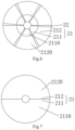
- the battery in the present embodiment differs from the battery in embodiment 1 in that: as shown in FIG. 6 , the battery cell 2 comprises battery cell electrode tabs 21 and battery cell non-electrode tabs 22 provided at intervals circumferentially along the battery cell 2.
- the battery cell electrode tabs 21 can be divided into a first battery cell part 211 and a second battery cell part 212, wherein the second battery cell part 212 is provided on the outer side of the first battery cell part 211. Similar to the above, the first battery cell part 211 comprises only positive electrode tabs but no negative electrode tabs, and the second battery cell part 212 comprises only negative electrode tabs but no positive electrode tabs, and the battery cell non-electrode tabs 22 comprises no tabs.
- the battery cell non-electrode tabs 22 comprises neither positive nor negative current collector, it can alleviate, to a certain extent, the problem of creasing of the battery cell 2 due to the uneven thickness of the battery cell 2 in the axial direction during the winding process of the battery cell 2.
- the structure of the positive current collector plate 33 and the negative current collector plate 34 in the present embodiment is the same as in embodiment 1, i.e., when the positive current collector plate 33 is provided on the battery cell 2, the positive current collector plate 33 will be located above the first battery cell part 211 and the battery cell non-electrode tabs 22 which is between the two adjacent first battery cell part 211, and when the negative current collector plate 34 is provided on the battery cell 2, the negative current collector plate 34 will be located above the second battery cell part 212 and the battery cell non-electrode tabs 22 which is between the two adjacent second battery cell parts 212. It is to be understood that the method of the preparation of the battery cell 2 is similar to that of the battery cell 2 in embodiment 1. Positive and negative electrode sheets are simply required to retain positive or negative current collectors at the corresponding areas where positive or negative electrode tabs need to be formed.
- the present embodiment discloses a battery.
- the battery in the present embodiment differs from the battery in Embodiment 1 in that: as shown in FIG. 7 to FIG. 9 , the battery cell 2 comprises the first battery cell part 211 and the second battery cell part 212, which are radially symmetrically provided, wherein the first battery cell part 211 comprises only positive electrode tabs and no negative electrode tabs, and the second battery cell part 212 comprises only negative electrode tabs and no positive electrode tabs, and the positive current collector plate 33 is provided on the first battery cell part 211 and the negative current collector plate 34 is provided on the second battery cell part 212.
- FIG. 7 it may be seen that both the first battery cell part 211 and the second battery cell part 212 are semi-circular structure.
- the positive current collector plate 33 may be provided in a semi-circular shaped structure, and the negative current collector plate 34 may be provided in a semi-ring shaped structure. That is, the structures of positive current collector plate 33 and negative current collector plate 34 are different from those provided in embodiment 1 and embodiment 2.
- the positive current collector plate 33 is provided on a side of the negative current collector plate 34, instead of on the inner ring of the negative current collector plate 34.
- the ratio of the radius of the positive current collector plate 33 to the radius of the outer ring of the negative current collector plate 34 ranges from 0.45 to 0.7.
- the ratio of the outer diameter of the positive electrode column 31 to the outer diameter of the cover plate 32 ranges from 0.2 to 0.7.
- the thickness of the cover plate 32 ranges from 0.4 mm to 1.5 mm.
- the thickness of the positive current collector plate 33 ranges from 0.1 mm to 0.5 mm.
- the thickness of the negative current collector plate 34 ranges from 0.1 mm to 0.3 mm.
- the positive current collector plate 33 is welded to the positive electrode column 31.
- the positive current collector plate 33 should not exceed the position of the winding hole formed by the battery cell 2 during the winding process, i.e. the distance between the positive current collector plate 33 and the negative current collector plate 34 is relatively large, so that the structure of the insulating part 35 can be omitted to simplify the battery assembly process.
- the positive electrode column 31 is welded to the battery cell 2 through the positive collector plate 33, hence there is a distance between the positive electrode column 31 and the battery cell 2. Therefore, even if the positive electrode column 31 is provided in the middle of the battery cell 2, the positive electrode column 31 is still not in contact with the second battery cell part 212, i.e. no short circuit will occur.
Landscapes
- Chemical & Material Sciences (AREA)
- Chemical Kinetics & Catalysis (AREA)
- Electrochemistry (AREA)
- General Chemical & Material Sciences (AREA)
- Engineering & Computer Science (AREA)
- Manufacturing & Machinery (AREA)
- Connection Of Batteries Or Terminals (AREA)
- Secondary Cells (AREA)
Abstract
Description
- The present application claims priority from
Chinese patent application No. 202210790503.8, filed to China Patent Office on July 05, 2022 Chinese patent application No. 202221727435.2, filed to China Patent Office on July 05, 2022 - The present application relates to the field of battery technology, for example, to a battery.
- The volumetric energy density is an important performance indicator of the battery, and the volumetric energy density directly determines the working time of the products using the battery. In the related technology, whether the battery is single electrode tab, multiple electrode tab or full electrode tab, most of them are provided with positive electrode tab or negative electrode tab at both ends of the winding core, and then the positive electrode tab is connected to the positive electrode column of the cover plate, and the negative electrode tab is connected to the negative electrode column of the cover plate. This structure will increase the height of the battery in the axial direction, which will lead to the reduction of the space utilization of the battery.
- This application provides a battery that may effectively improve the space utilization of the battery and enhance the volumetric energy density of the battery.
- The present application provides a battery, comprising:
- a housing, an end of the housing comprises an opening;
- a battery cell, an end of the battery cell comprises a first electrode tab and a second electrode tab with different electrode polarities, the battery cell is provided in the housing, the first electrode tab and the second electrode tab are both provided towards the opening;
- an end cover structure covered on the opening, the end cover structure comprises a first electrode connecting part and a second electrode connecting part, the first electrode connecting part is electrically connected with the first electrode tab, the second electrode connecting part is electrically connected with the second electrode tab, and the first electrode connecting part and the second electrode connecting part are connected by an insulating sealing part.
-
-
FIG. 1 is an exploded view of the battery provided inembodiment 1 of the present application. -
FIG. 2 is an exploded view of the battery provided inembodiment 1 of the present application. -
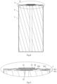
FIG. 3 is a cross-sectional view of the battery cell provided inembodiment 1 of the present application. -
FIG. 4 is a cross-sectional view of the battery provided inembodiment 1 of the present application. -
FIG. 5 is an enlarged view at A inFIG. 4 . -
FIG. 6 is a cross-sectional view of the battery cell provided inembodiment 2 of the present application; -
FIG. 7 is a cross-sectional view of the battery cell provided inembodiment 3 of the present application; -
FIG. 8 is a cross-sectional view of the battery provided inembodiment 3 of the present application. -
FIG. 9 is an enlarged view at B inFIG. 8 .
1: housing; 2: battery cell; 20: groove; 21: battery cell electrode tabs; 211: first battery cell part; 212: second battery cell part; 22: battery cell non-electrode tabs; 2110: first electrode tab; 2120: second electrode tab; 3: end cover structure; 310: first electrode connecting part; 31: positive electrode column; 311: accommodating slot; 320: second electrode connecting part; 32: cover plate; 321: connecting concave part; 33: positive current collector plate; 34: negative current collector plate; 341: connecting convex part; 35: insulating part; 351: first insulating part; 352: second insulating part; 360: insulating sealing part; 36: first sealing ring; 37: second sealing ring; 4: insulating gasket; 5: insulating cover. - It is to be understood that the embodiments described herein are only intended to explain the present application. It is also to be noted that, for ease of description, the attached drawings show only a portion, but not all, of the embodiments relating to the present application.
- In the description of this application, the terms "connect", "join" and "fix" shall be understood in a broad sense unless otherwise explicitly specified and limited. For example, it can be a fixed connection, a detachable connection, or an integral body; it can be a mechanical connection or an electrical connection; it can be a direct connection or an indirect connection through an intermediate medium, and it can be a connection within two components or an interaction relationship between two components. To a person of ordinary skill in the art, the actual meaning of the above terms in the present application may be understood according to the actual situation.
- In the present application, unless otherwise explicitly specified and limited, the first feature "above" or "under" the second feature may include that the first and second features are in direct contact, or that the first and second features are not in direct contact but are in contact through another feature between them. Furthermore, the first feature being "on top of", "over" and "above" the second feature includes the first feature being directly above and obliquely above the second feature, or simply indicating that the level of the first feature is higher than the level of the second feature. The first feature being "beneath", "under" and "below" the second feature includes the first feature being directly below and obliquely below the second feature, or simply indicating that the level of the first feature is lower than the level of the second feature.
- In the description of the present embodiments, the terms "up", "down", "left", "right" and other orientation or position relationships are based on the orientation or position relationships shown in the attached drawings. It is intended to facilitate description and simplify operation, not to indicate or imply that the referred device or element has a particular orientation, or is constructed and operated in a particular orientation. Therefore, they may not be construed as a limitation of the present invention. In addition, the terms "first" and "second" are used for descriptive distinction and have no special meaning.
- The present application is described below in conjunction with the attached drawings and by means of preferred embodiments.
- As shown in
Fig. 1 to Fig. 5 , the present embodiment provides a battery that may effectively improve the space utilization of the battery in the axial direction, enhance the volumetric energy density of the battery, and ensure the performance of the product. The battery includes ahousing 1, abattery cell 2 and anend cover structure 3. An end of thehousing 1 comprises an opening. Thebattery cell 2 may be provided inside thehousing 1 through the opening. Theend cover structure 3 covers the opening, which may enclose thebattery cell 2 in thehousing 1. Theend cover structure 3 is electrically connected to thebattery cell 2 to ensure the regular operation of the battery. - In order to improve the space utilization in the axial direction of the battery, in the present embodiment, an end of the
battery cell 2 comprises afirst electrode tab 2110 and asecond electrode tab 2120 with different electrode polarities, and thefirst electrode tab 2110 and thesecond electrode tab 2120 are both set toward the opening when thebattery cell 2 is placed in thehousing 1. Theend cover structure 3 covers the opening, and theend cover structure 3 comprises a firstelectrode connecting part 310 and a secondelectrode connecting part 320, wherein the firstelectrode connecting part 310 is electrically connected to thefirst electrode tab 2110 and the secondelectrode connecting part 320 is electrically connected to thesecond electrode tab 2120, and the firstelectrode connecting part 310 and the secondelectrode connecting part 320 are connected by aninsulating sealing part 360 to avoid short-circuit caused by the contact between the positive electrode and the negative electrode of the battery. - Preferably, in the present embodiment, the
first electrode tab 2110 is a positive electrode tab. The first electrodetab connecting part 310 comprises apositive electrode column 31 and a positivecurrent collector plate 33. The positivecurrent collector plate 33 is provided on thebattery cell 2. The positive electrode tab is connected to thepositive electrode column 31 by the positivecurrent collector plate 33. Thesecond electrode tab 2120 is a negative electrode tab. The second electrodetab connecting part 320 comprises acover plate 32 and a negativecurrent collector plate 34. The negativecurrent collector plate 34 is provided on thebattery cell 2. The negative electrode tab is connected to thecover plate 32 by the negativecurrent collector plate 34. - As shown in
FIG. 3 , in the present embodiment, the firstbattery cell part 211 is a circular structure. The secondbattery cell part 212 is a ring-shaped structure. As may be understood, thebattery cell 2 is formed by winding the positive electrode sheet, the diaphragm and the negative electrode sheet. The width side of the positive electrode sheet comprises a positive current collector. The width side of the negative electrode sheet comprises a negative current collector. In order to make thebattery cell 2 formed by winding, which comprises only positive electrode tabs without negative electrode tabs in the firstbattery cell part 211 and comprises only negative electrode tabs without positive electrode tabs in the secondbattery cell part 212, part of the negative current collector and part of the positive current collector may be removed before winding. In other words, during the initial winding process, the wound positive electrode sheet comprises the positive current collector and the negative electrode sheet comprises no negative current collector. In the subsequent winding process, the wound positive electrode sheet comprises no positive current collector and the wound negative electrode sheet comprises negative current collector. In order to ensure the electrical connection between the positive electrode tab and the positivecurrent collector plate 33 and the electrical connection between negative electrode tab and the negativecurrent collector plate 34, the negativecurrent collector plate 34 is provided according to the shape of the secondbattery cell part 212 on the secondbattery cell part 212, and the positivecurrent collector plate 33 is provided according to the shape of the firstbattery cell part 212 on the firstbattery cell part 211. Then, the side of the positivecurrent collector plate 33 that is not in contact with thebattery cell 2 is welded to thepositive electrode column 31, and the side of the negativecurrent collector plate 34 that is not in contact with thebattery cell 2 is welded to thecover plate 32. - In one embodiment, the
end cover structure 3 further comprises an insulatingpart 35, which is provided on thebattery cell 2, wherein one side of the insulatingpart 35 is connected to the positivecurrent collector plate 33, and the other side of the insulatingpart 35 is connected to the negativecurrent collector plate 34, so as to avoid a short-circuit caused by the contact between the positivecurrent collector plate 33 and the negativecurrent collector plate 34 due to the vibration of thebattery cell 2. Alternatively, the positivecurrent collector plate 33 and the negativecurrent collector plate 34 are adhesively connected to the insulatingpart 35. - In order to ensure that the positive
current collector plate 33 and the negativecurrent collector plate 34 are always separated by the insulatingpart 35, the insulatingpart 35 provided in the present embodiment comprises a first insulatingpart 351 and a secondinsulating part 352 that are not located in the same plane, wherein the first insulatingpart 351 and the second insulatingpart 352 are connected by a transitional section set at an oblique angle. When the first insulatingpart 351 is connected to the positivecurrent collector plate 33, the positivecurrent collector plate 33 is adhesively connected to the side of the first insulatingpart 351 that is facing away from thebattery cell 2. When the second insulatingpart 352 is connected to the negativecurrent collector plate 34, the negativecurrent collector plate 34 is adhesively connected to the side of the second insulatingpart 352 near thebattery cell 2. That is, in the horizontal direction, the positivecurrent collector plate 33 and the negativecurrent collector plate 34 are always located on different sides of the transitional section. Even if the positivecurrent collector plate 33 and negativecurrent collector plate 34 are infinitely close to each other, they will still be separated by the transitional section. - Alternatively, an end side of the
battery cell 2 comprises agroove 20, wherein the insulatingpart 35 is provided in thegroove 20. As can be seen inFIG. 5 , the depth of thegroove 20 may be identical to the thickness of the first insulatingpart 351, wherein when the first insulatingpart 351 is provided in thegroove 20, the side facing away from thebattery cell 2 can abut with the side of the positivecurrent collector plate 33 abutting against thebattery cell 2, while the side of the second insulatingpart 352 close to thebattery cell 2 needs to be in contact with the side of the negativecurrent collector plate 34 facing away from thebattery cell 2. Correspondingly, the positivecurrent collector plate 33 is a circular structure and the negativecurrent collector plate 34 is a ring-shaped structure. Therefore, the insulatingpart 35 is a ring-shaped structure between the positivecurrent collector plate 33 and the negativecurrent collector plate 34. Thegroove 20 is a ring-shaped groove. - In one embodiment, in order to ensure the strength of the connection between the
cover plate 32 and the negativecurrent collector plate 34, thecover plate 32 comprises a connectingconcave part 321 provided towards thebattery cell 2, while the negativecurrent collector plate 34 comprises a connectingconvex part 341 facing away from thebattery cell 2, and the connectingconvex part 341 is connected with the connectingconcave part 321. Since welding of the connection may cause welding defects in the part of thecover plate 32, the welding effect can be ensured by filling with glue applied to the connectingconvex part 341 after welding. - Alternatively, the
positive electrode column 31 is a columnar structure and thecover plate 32 is a ring-shaped structure, wherein aninner ring 322 of thecover plate 32 is connected to thepositive electrode column 31 by an insulating sealingpart 360 and anouter ring 323 of thecover plate 32 is connected to ahousing 1. That is, thecover plate 32 is sleeved on thepositive electrode column 31. During the riveting of thecover plate 32 and thepositive electrode column 31, the circumferential surface of thepositive electrode column 31 will be formed with anaccommodating slot 311. In order to ensure the sealing effect of the connection between thecover plate 32 and thepositive electrode column 31, and to avoid short-circuit caused by the contact between thecover plate 32 and thepositive electrode column 31, the insulating sealingpart 360 may be sleeved between thecover plate 32 and thepositive electrode column 31. When thecover plate 32 and thepositive electrode column 31 are riveted, the insulating sealingpart 360 will be clamped between theaccommodating slot 311 and thecover plate 32. This completely prevents contact between thecover plate 32 and thepositive electrode column 31. Alternatively, the insulating sealingpart 360 is a plastic ring, which is elastic and can achieve an interference fit between thecover plate 32 and thepositive electrode column 31 to ensure the sealing effect. - In the present embodiment, the ratio of the outer diameter of the
positive electrode column 31 to the outer diameter of thecover plate 32 ranges from 0.2 to 0.7. The ratio of the outer diameter of the positivecurrent collector plate 33 to the outer diameter of the negativecurrent collector plate 34 ranges from 0.45 to 0.7. The thickness of thecover plate 32 ranges from 0.4 mm to 1.5 mm. The thickness of the positivecurrent collector plate 33 ranges from 0.1 mm to 0.5 mm. The thickness of the negativecurrent collector plate 34 ranges from 0.1mm-0.3mm. - Since the insulating seal needs to ensure that the upper surface, lower surface and end surface of the
cover plate 32 are not in contact with thepositive electrode column 31, the insulating sealingpart 360 needs to be wrapped around each of the aforementioned positions. In the present embodiment, the insulating sealingpart 360 comprises afirst sealing ring 36 and asecond sealing ring 37, both of which are ring-shaped, wherein thefirst sealing ring 36 comprises a first sealing ring body and a connecting part convexly provided around the inner ring of thefirst sealing ring 36. When thefirst sealing ring 36, thecover plate 32 and thesecond sealing ring 37 are sequentially sleeved on thepositive electrode column 31, thesecond sealing ring 37 and thefirst sealing ring 36 will be abut by the abutting part, and isolate theinner ring 322 of thecover plate 32 and thepositive electrode column 31. - Alternatively, as shown in
FIG. 1 , the battery further comprises an insulatinggasket 4 and an insulatingcover 5. When thebattery cell 2 is provided in thehousing 1, the insulatinggasket 4 is provided on the side of thebattery cell 2 without the tab. The insulatingcover 5 is sleeved on thebattery cell 2, and the insulatinggasket 4 is sandwiched between the insulatingcover 5 and thebattery cell 2, so as to ensure the insulation of thebattery cell 2 and thehousing 1. - The battery provided in the present embodiment comprises a housing, a battery cell and an end cover structure, an end of the housing comprises an opening. The battery cell may be provided inside the housing through the opening. The end cover structure covers the opening to close the housing and is electrically connected to the battery cell. Only one end of the housing is provided with the end cover structure, which can effectively improve the space utilization in the axial direction of the battery, increase the volumetric energy density of the battery and ensure the performance of the product. Alternatively, an end of the battery cell comprises a first electrode tab and a second electrode tab with different electrode polarities. When the battery cell is provided in the housing, both the first electrode tab and the second electrode tab are provided towards the opening. The end cover structure comprises a first electrode connecting part and a second electrode connecting part. When the end cover structure is covered at the opening and connected to the housing, the first electrode connecting part is electrically connected to the first electrode tab and the second electrode connecting part is electrically connected to the second electrode tab. The first electrode connecting part and the second electrode connecting part are also connected by an insulating sealing part to avoid a short-circuit caused by the contact between the positive electrode and negative electrode of the battery, so as to ensure the performance of the battery.
- The present embodiment discloses a battery. The battery in the present embodiment differs from the battery in
embodiment 1 in that: as shown inFIG. 6 , thebattery cell 2 comprises batterycell electrode tabs 21 and battery cellnon-electrode tabs 22 provided at intervals circumferentially along thebattery cell 2. The batterycell electrode tabs 21 can be divided into a firstbattery cell part 211 and a secondbattery cell part 212, wherein the secondbattery cell part 212 is provided on the outer side of the firstbattery cell part 211. Similar to the above, the firstbattery cell part 211 comprises only positive electrode tabs but no negative electrode tabs, and the secondbattery cell part 212 comprises only negative electrode tabs but no positive electrode tabs, and the battery cellnon-electrode tabs 22 comprises no tabs. Since the battery cellnon-electrode tabs 22 comprises neither positive nor negative current collector, it can alleviate, to a certain extent, the problem of creasing of thebattery cell 2 due to the uneven thickness of thebattery cell 2 in the axial direction during the winding process of thebattery cell 2. - The structure of the positive
current collector plate 33 and the negativecurrent collector plate 34 in the present embodiment is the same as inembodiment 1, i.e., when the positivecurrent collector plate 33 is provided on thebattery cell 2, the positivecurrent collector plate 33 will be located above the firstbattery cell part 211 and the battery cellnon-electrode tabs 22 which is between the two adjacent firstbattery cell part 211, and when the negativecurrent collector plate 34 is provided on thebattery cell 2, the negativecurrent collector plate 34 will be located above the secondbattery cell part 212 and the battery cellnon-electrode tabs 22 which is between the two adjacent secondbattery cell parts 212. It is to be understood that the method of the preparation of thebattery cell 2 is similar to that of thebattery cell 2 inembodiment 1. Positive and negative electrode sheets are simply required to retain positive or negative current collectors at the corresponding areas where positive or negative electrode tabs need to be formed. - Besides, the rest of the structure of the battery provided in the present embodiment is the same as that of the battery in
embodiment 1, and hence will not be further repeated here. - The present embodiment discloses a battery. The battery in the present embodiment differs from the battery in
Embodiment 1 in that: as shown inFIG. 7 to FIG. 9 , thebattery cell 2 comprises the firstbattery cell part 211 and the secondbattery cell part 212, which are radially symmetrically provided, wherein the firstbattery cell part 211 comprises only positive electrode tabs and no negative electrode tabs, and the secondbattery cell part 212 comprises only negative electrode tabs and no positive electrode tabs, and the positivecurrent collector plate 33 is provided on the firstbattery cell part 211 and the negativecurrent collector plate 34 is provided on the secondbattery cell part 212. Referring toFIG. 7 , it may be seen that both the firstbattery cell part 211 and the secondbattery cell part 212 are semi-circular structure. The positivecurrent collector plate 33 may be provided in a semi-circular shaped structure, and the negativecurrent collector plate 34 may be provided in a semi-ring shaped structure. That is, the structures of positivecurrent collector plate 33 and negativecurrent collector plate 34 are different from those provided inembodiment 1 andembodiment 2. The positivecurrent collector plate 33 is provided on a side of the negativecurrent collector plate 34, instead of on the inner ring of the negativecurrent collector plate 34. - Similar to the sizes of each part of the
end cover structure 3 inembodiment 1, the ratio of the radius of the positivecurrent collector plate 33 to the radius of the outer ring of the negativecurrent collector plate 34 ranges from 0.45 to 0.7. In addition, the ratio of the outer diameter of thepositive electrode column 31 to the outer diameter of thecover plate 32 ranges from 0.2 to 0.7. The thickness of thecover plate 32 ranges from 0.4 mm to 1.5 mm. The thickness of the positivecurrent collector plate 33 ranges from 0.1 mm to 0.5 mm. The thickness of the negativecurrent collector plate 34 ranges from 0.1 mm to 0.3 mm. - Under this arrangement, the positive
current collector plate 33 is welded to thepositive electrode column 31. The positivecurrent collector plate 33 should not exceed the position of the winding hole formed by thebattery cell 2 during the winding process, i.e. the distance between the positivecurrent collector plate 33 and the negativecurrent collector plate 34 is relatively large, so that the structure of the insulatingpart 35 can be omitted to simplify the battery assembly process. Alternatively, thepositive electrode column 31 is welded to thebattery cell 2 through thepositive collector plate 33, hence there is a distance between thepositive electrode column 31 and thebattery cell 2. Therefore, even if thepositive electrode column 31 is provided in the middle of thebattery cell 2, thepositive electrode column 31 is still not in contact with the secondbattery cell part 212, i.e. no short circuit will occur. - Besides, the rest of the structure of the battery provided in the present embodiment is the same as that of the battery in
embodiment 1, and hence will not be further repeated here.
Claims (19)
- A battery comprising:a housing (1), an end of the housing (1) comprises an opening;a battery cell (2), an end of the battery cell (2) comprises a first electrode tab (2110) anda second electrode tab (2120) with different electrode polarities, the battery cell (2) is provided in the housing (1), the first electrode tab (2110) and the second electrode tab (2120) are both provided towards the opening;an end cover structure (3) covered on the opening, the end cover structure (3) comprises a first electrode connecting part (310) and a second electrode connecting part (320), the first electrode connecting part (310) is electrically connected with the first electrode tab (2110), the second electrode connecting part (320) is electrically connected with the second electrode tab (2120), and the first electrode connecting part (310) and the second electrode connecting part (320) are connected by an insulating sealing part (360).
- The battery according to claim 1, wherein the first electrode tab (2110) is a positive electrode tab, the first electrode connecting part (310) comprises a positive electrode column (31) and a positive current collector plate (33), and the positive electrode column (31) is connected with the positive electrode tab by the positive current collector plate (33);
the second electrode tab (2120) is a negative electrode tab, the second electrode connecting part (320) comprises a cover plate (32) and a negative current collector plate (34), the cover plate (32) is connected with the negative electrode tab by the negative current collector plate (34), the positive electrode column (31) is connected with the cover plate (32) by the insulating sealing part (360). - The battery according to claim 2, wherein the battery cell (2) comprises a first battery cell part (211) and a second battery cell part (212), the second battery cell part (212) is provided along a circumferential direction of the first battery cell part (211), the first battery cell part (211) comprises the positive electrode tab, the positive current collector plate (33) is provided on the first battery cell part (211), the second battery cell part (212) comprises the negative electrode tab, the negative current collector plate (34) is provided on the second battery cell part (212).
- The battery according to claim 2, wherein the battery cell (2) comprises battery cell electrode tabs (21) and battery cell non-electrode tabs (22) provided at intervals along a circumferential direction of the battery cell (2), the battery cell electrode tabs (21) comprises first battery cell parts (211) and second battery cell parts (212) provided outside of the first battery cell part (211), the first battery cell part (211) comprises the positive electrode tab, the second battery cell part (212) comprises the negative electrode tab, the positive current collector plate (33) is provided on the first battery cell part (211) and the battery cell non-electrode tabs (22) between two adjacent first battery cell parts (211), and the negative current collector plate (34) is provided on the second battery cell part (212) and the battery cell non-electrode tabs (22) which is between two adjacent second battery cell parts (212).
- The battery according to claim 2, wherein the battery cell (2) comprises a first battery cell part (211) and a second battery cell part (212), which are radially symmetrically provided, the first battery cell part (211) comprises the positive electrode tab, the positive current collector plate (33) is provided on the first battery cell part (211), the second battery cell part (212) comprises the negative electrode tab, and the negative current collector plate (34) is provided on the second battery cell part (212).
- The battery according to claim 3, wherein the end cover structure (3) further comprises an insulating part (35), the insulating part (35) is provided on the battery cell (2), and a side of the insulating part (35) is connected with the positive current collector plate (33), another side of the insulating part (35) is connected with the negative current collector plate (34).
- The battery according to claim 6, wherein the insulating part (35) comprises an first insulating part (351) and an second insulating part (352), the first insulating part (351) and the second insulating part (352) are not located on the same plane, the positive current collector plate (33) is connected to a side of the first insulating part (351) facing away from the battery cell (2), the negative current collector plate (34) is connected to a side of the second insulating part (352) near the battery cell (2).
- The battery according to claim 6, wherein a groove (20) is provided on an end of the battery cell (2), the insulating part (35) is provided in the groove (20).
- The battery according to claim 4, wherein the end cover structure (3) further comprises an insulating part (35), the insulating part (35) is provided on the battery cell (2), and a side of the insulating part (35) is connected with the positive current collector plate (33), another side of the insulating part (35) is connected with the negative current collector plate (34).
- The battery according to claim 9, wherein the insulating part (35) comprises a first insulating part (351) and an second insulating part (352), the first insulating part (351) and the second insulating part (352) are not located on the same plane, the positive current collector plate (33) is connected to a side of the first insulating part (351) facing away from the battery cell (2), the negative current collector plate (34) is connected to a side of the second insulating part (352) near the battery cell (2).
- The battery according to claim 9, wherein a groove (20) is provided on an end of the battery cell (2), the insulating part (35) is provided in the groove (20).
- The battery according to claim 2, wherein the negative current collector plate (34) comprises a connecting convex part (341) facing away from the battery cell (2), the cover plate (32) comprises a connecting concave part (321) facing the battery cell (2), and the connecting convex part (341) abuts the connecting concave part (321).
- The battery according to claim 3, wherein the negative current collector plate (34) comprises a connecting convex part (341) facing away from to the battery cell (2), the cover plate (32) comprises a connecting concave part (321) facing the battery cell (2), and the connecting convex part (341) abuts the connecting concave part (321).
- The battery according to claim 4, wherein the negative current collector plate (34) comprises a connecting convex part (341) facing away from to the battery cell (2), the cover plate (32) comprises a connecting concave part (321) facing the battery cell (2), and the connecting convex part (341) abuts the connecting concave part (321).
- The battery according to claim 5, wherein the negative current collector plate (34) comprises a connecting convex part (341) facing away from to the battery cell (2), the cover plate (32) comprises a connecting concave part (321) facing the battery cell (2), and the connecting convex part (341) abuts the connecting concave part (321).
- The battery according to claim 2, wherein the positive electrode column (31) and the cover plate (32) are riveted to form an accommodating slot (311) on the positive electrode column (31), the insulating sealing part (360) is sandwiched between the accommodating slot (311) and the cover plate (32).
- The battery according to claim 3, wherein the positive electrode column (31) and the cover plate (32) are riveted to form an accommodating slot (311) on the positive electrode column (31), the insulating sealing part (360) is sandwiched between the accommodating slot (311) and the cover plate (32).
- The battery according to claim 4, wherein the positive electrode column (31) and the cover plate (32) are riveted to form an accommodating slot (311) on the positive electrode column (31), the insulating sealing part (360) is sandwiched between the accommodating slot (311) and the cover plate (32).
- The battery according to claim 5, wherein the positive electrode column (31) and the cover plate (32) are riveted to form an accommodating slot (311) on the positive electrode column (31), the insulating sealing part (360) is sandwiched between the accommodating slot (311) and the cover plate (32).
Applications Claiming Priority (3)
| Application Number | Priority Date | Filing Date | Title |
|---|---|---|---|
| CN202221727435.2U CN218039493U (en) | 2022-07-05 | 2022-07-05 | a battery |
| CN202210790503.8A CN114976404A (en) | 2022-07-05 | 2022-07-05 | Battery with a battery cell |
| PCT/CN2022/120767 WO2023173716A1 (en) | 2022-07-05 | 2022-09-23 | Battery |
Publications (2)
| Publication Number | Publication Date |
|---|---|
| EP4276987A1 true EP4276987A1 (en) | 2023-11-15 |
| EP4276987A4 EP4276987A4 (en) | 2025-03-19 |
Family
ID=88016265
Family Applications (1)
| Application Number | Title | Priority Date | Filing Date |
|---|---|---|---|
| EP22818598.9A Pending EP4276987A4 (en) | 2022-07-05 | 2022-09-23 | BATTERY |
Country Status (4)
| Country | Link |
|---|---|
| US (1) | US12562422B2 (en) |
| EP (1) | EP4276987A4 (en) |
| DE (1) | DE212022000366U1 (en) |
| WO (1) | WO2023173716A1 (en) |
Families Citing this family (1)
| Publication number | Priority date | Publication date | Assignee | Title |
|---|---|---|---|---|
| SE2351120A1 (en) * | 2023-09-28 | 2025-03-29 | Northvolt Ab | A cylindrical battery cell |
Family Cites Families (21)
| Publication number | Priority date | Publication date | Assignee | Title |
|---|---|---|---|---|
| KR100589347B1 (en) * | 2004-04-27 | 2006-06-14 | 삼성에스디아이 주식회사 | Secondary battery |
| WO2013001821A1 (en) * | 2011-06-28 | 2013-01-03 | 日本ケミコン株式会社 | Electricity storage device and method for manufacturing electricity storage device |
| CN102856514B (en) | 2011-06-28 | 2015-07-22 | 比亚迪股份有限公司 | A cover plate assembly and lithium ion battery containing the cover plate assembly |
| EP2988349A3 (en) * | 2014-08-14 | 2016-06-15 | Samsung SDI Co., Ltd. | Battery having cap assembly comprising a insulating spacer having a groove and an electrode lead |
| JP6868400B2 (en) * | 2017-01-17 | 2021-05-12 | Fdk株式会社 | Cylindrical battery enclosure, tubular battery |
| CN207883864U (en) * | 2018-01-22 | 2018-09-18 | 东莞市昂跃电子有限公司 | Cylindrical battery positive protection device with USB charging function |
| CN209328960U (en) | 2018-12-29 | 2019-08-30 | 苏州安靠电源有限公司 | Battery cap and cylindrical battery |
| CN210074010U (en) | 2019-08-01 | 2020-02-14 | 华霆(合肥)动力技术有限公司 | Composite tab and battery cell |
| CN111370601A (en) * | 2020-04-14 | 2020-07-03 | 广东国光电子有限公司 | Lithium Ion Battery |
| CN212907981U (en) * | 2020-08-20 | 2021-04-06 | 华霆(合肥)动力技术有限公司 | Monomer electricity core, battery module and electric motor car |
| CN214411447U (en) * | 2021-03-25 | 2021-10-15 | 浙江金羽新能源科技有限公司 | Button cell |
| CN215418489U (en) | 2021-06-21 | 2022-01-04 | 东莞锂微电子科技有限公司 | Steel shell button cell with double explosion-proof structure |
| CN113314763A (en) * | 2021-06-24 | 2021-08-27 | 星恒电源股份有限公司 | Cylindrical battery roll core and manufacturing method thereof |
| CN215911549U (en) * | 2021-07-23 | 2022-02-25 | 曙鹏科技(深圳)有限公司 | Button cell |
| CN216015526U (en) | 2021-07-27 | 2022-03-11 | 曙鹏科技(深圳)有限公司 | Button cell |
| CN215266605U (en) | 2021-07-30 | 2021-12-21 | 宁德时代新能源科技股份有限公司 | Battery cells, batteries and electrical equipment |
| CN113571848B (en) * | 2021-08-25 | 2025-08-08 | 星恒电源股份有限公司 | High-rate, high-capacity, minimalist battery sealing cover, cylindrical battery, and assembly process |
| CN216793944U (en) | 2022-02-24 | 2022-06-21 | 中创新航科技股份有限公司 | Battery and battery pack |
| CN114628863A (en) | 2022-04-13 | 2022-06-14 | 蔚来汽车科技(安徽)有限公司 | Columnar battery |
| CN114976404A (en) * | 2022-07-05 | 2022-08-30 | 湖北亿纬动力有限公司 | Battery with a battery cell |
| CN218039493U (en) | 2022-07-05 | 2022-12-13 | 湖北亿纬动力有限公司 | a battery |
-
2022
- 2022-09-23 DE DE212022000366.7U patent/DE212022000366U1/en active Active
- 2022-09-23 EP EP22818598.9A patent/EP4276987A4/en active Pending
- 2022-09-23 WO PCT/CN2022/120767 patent/WO2023173716A1/en not_active Ceased
- 2022-12-27 US US18/088,804 patent/US12562422B2/en active Active
Also Published As
| Publication number | Publication date |
|---|---|
| US12562422B2 (en) | 2026-02-24 |
| DE212022000366U1 (en) | 2024-10-18 |
| WO2023173716A1 (en) | 2023-09-21 |
| US20240014487A1 (en) | 2024-01-11 |
| EP4276987A4 (en) | 2025-03-19 |
Similar Documents
| Publication | Publication Date | Title |
|---|---|---|
| EP4303998A1 (en) | Casing assembly and battery | |
| CN217589153U (en) | Housing assembly and battery | |
| CN116505206B (en) | Cylindrical secondary battery | |
| CN110854306A (en) | Winding type bean type battery | |
| EP3764418A1 (en) | Cap assembly and secondary battery | |
| WO2013111318A1 (en) | Hermetic battery | |
| US20230163432A1 (en) | Button battery | |
| CN112366394A (en) | Button cell | |
| US11777162B2 (en) | Cap assembly and secondary battery | |
| EP3799146A1 (en) | Top cover assembly and secondary battery | |
| JP4479013B2 (en) | Cylindrical battery | |
| CN112820948A (en) | Cylindrical lithium ion battery | |
| CN114976404A (en) | Battery with a battery cell | |
| CN110854305A (en) | wound bean battery | |
| EP4276987A1 (en) | Battery | |
| CN116130745B (en) | Battery cell | |
| JP4596842B2 (en) | Sealed battery and manufacturing method thereof | |
| CN216773468U (en) | Electrode structure, battery and battery pack | |
| CN218039493U (en) | a battery | |
| CN217507616U (en) | Battery with a battery cell | |
| CN213184425U (en) | Button cell | |
| CN209747633U (en) | Secondary battery | |
| CN209947672U (en) | Electrochemical energy storage device | |
| EP4398387A1 (en) | Top cover structure and battery | |
| EP4297171A1 (en) | Connector and battery |
Legal Events
| Date | Code | Title | Description |
|---|---|---|---|
| STAA | Information on the status of an ep patent application or granted ep patent |
Free format text: STATUS: UNKNOWN |
|
| STAA | Information on the status of an ep patent application or granted ep patent |
Free format text: STATUS: THE INTERNATIONAL PUBLICATION HAS BEEN MADE |
|
| PUAI | Public reference made under article 153(3) epc to a published international application that has entered the european phase |
Free format text: ORIGINAL CODE: 0009012 |
|
| STAA | Information on the status of an ep patent application or granted ep patent |
Free format text: STATUS: REQUEST FOR EXAMINATION WAS MADE |
|
| 17P | Request for examination filed |
Effective date: 20221216 |
|
| AK | Designated contracting states |
Kind code of ref document: A1 Designated state(s): AL AT BE BG CH CY CZ DE DK EE ES FI FR GB GR HR HU IE IS IT LI LT LU LV MC MK MT NL NO PL PT RO RS SE SI SK SM TR |
|
| A4 | Supplementary search report drawn up and despatched |
Effective date: 20250214 |
|
| RIC1 | Information provided on ipc code assigned before grant |
Ipc: H01M 50/107 20210101ALI20250211BHEP Ipc: H01M 50/567 20210101ALI20250211BHEP Ipc: H01M 50/566 20210101ALI20250211BHEP Ipc: H01M 50/559 20210101ALI20250211BHEP Ipc: H01M 50/538 20210101ALI20250211BHEP Ipc: H01M 50/55 20210101ALI20250211BHEP Ipc: H01M 50/533 20210101ALI20250211BHEP Ipc: H01M 50/188 20210101ALI20250211BHEP Ipc: H01M 50/184 20210101ALI20250211BHEP Ipc: H01M 50/152 20210101AFI20250211BHEP |
|
| DAV | Request for validation of the european patent (deleted) | ||
| DAX | Request for extension of the european patent (deleted) |