EP4276957A1 - Low loss inlet header for fuel cells - Google Patents
Low loss inlet header for fuel cells Download PDFInfo
- Publication number
- EP4276957A1 EP4276957A1 EP23162137.6A EP23162137A EP4276957A1 EP 4276957 A1 EP4276957 A1 EP 4276957A1 EP 23162137 A EP23162137 A EP 23162137A EP 4276957 A1 EP4276957 A1 EP 4276957A1
- Authority
- EP
- European Patent Office
- Prior art keywords
- inlet
- vanes
- inlet header
- header
- defines
- Prior art date
- Legal status (The legal status is an assumption and is not a legal conclusion. Google has not performed a legal analysis and makes no representation as to the accuracy of the status listed.)
- Granted
Links
Images




Classifications
-
- H—ELECTRICITY
- H01—ELECTRIC ELEMENTS
- H01M—PROCESSES OR MEANS, e.g. BATTERIES, FOR THE DIRECT CONVERSION OF CHEMICAL ENERGY INTO ELECTRICAL ENERGY
- H01M8/00—Fuel cells; Manufacture thereof
- H01M8/24—Grouping of fuel cells, e.g. stacking of fuel cells
- H01M8/2465—Details of groupings of fuel cells
- H01M8/2483—Details of groupings of fuel cells characterised by internal manifolds
-
- H—ELECTRICITY
- H01—ELECTRIC ELEMENTS
- H01M—PROCESSES OR MEANS, e.g. BATTERIES, FOR THE DIRECT CONVERSION OF CHEMICAL ENERGY INTO ELECTRICAL ENERGY
- H01M8/00—Fuel cells; Manufacture thereof
- H01M8/24—Grouping of fuel cells, e.g. stacking of fuel cells
- H01M8/2465—Details of groupings of fuel cells
- H01M8/2484—Details of groupings of fuel cells characterised by external manifolds
-
- H—ELECTRICITY
- H01—ELECTRIC ELEMENTS
- H01M—PROCESSES OR MEANS, e.g. BATTERIES, FOR THE DIRECT CONVERSION OF CHEMICAL ENERGY INTO ELECTRICAL ENERGY
- H01M8/00—Fuel cells; Manufacture thereof
- H01M8/02—Details
- H01M8/0202—Collectors; Separators, e.g. bipolar separators; Interconnectors
- H01M8/0258—Collectors; Separators, e.g. bipolar separators; Interconnectors characterised by the configuration of channels, e.g. by the flow field of the reactant or coolant
-
- H—ELECTRICITY
- H01—ELECTRIC ELEMENTS
- H01M—PROCESSES OR MEANS, e.g. BATTERIES, FOR THE DIRECT CONVERSION OF CHEMICAL ENERGY INTO ELECTRICAL ENERGY
- H01M8/00—Fuel cells; Manufacture thereof
- H01M8/02—Details
- H01M8/0202—Collectors; Separators, e.g. bipolar separators; Interconnectors
- H01M8/0258—Collectors; Separators, e.g. bipolar separators; Interconnectors characterised by the configuration of channels, e.g. by the flow field of the reactant or coolant
- H01M8/026—Collectors; Separators, e.g. bipolar separators; Interconnectors characterised by the configuration of channels, e.g. by the flow field of the reactant or coolant characterised by grooves, e.g. their pitch or depth
-
- H—ELECTRICITY
- H01—ELECTRIC ELEMENTS
- H01M—PROCESSES OR MEANS, e.g. BATTERIES, FOR THE DIRECT CONVERSION OF CHEMICAL ENERGY INTO ELECTRICAL ENERGY
- H01M8/00—Fuel cells; Manufacture thereof
- H01M8/24—Grouping of fuel cells, e.g. stacking of fuel cells
- H01M8/2465—Details of groupings of fuel cells
- H01M8/2484—Details of groupings of fuel cells characterised by external manifolds
- H01M8/2485—Arrangements for sealing external manifolds; Arrangements for mounting external manifolds around a stack
-
- Y—GENERAL TAGGING OF NEW TECHNOLOGICAL DEVELOPMENTS; GENERAL TAGGING OF CROSS-SECTIONAL TECHNOLOGIES SPANNING OVER SEVERAL SECTIONS OF THE IPC; TECHNICAL SUBJECTS COVERED BY FORMER USPC CROSS-REFERENCE ART COLLECTIONS [XRACs] AND DIGESTS
- Y02—TECHNOLOGIES OR APPLICATIONS FOR MITIGATION OR ADAPTATION AGAINST CLIMATE CHANGE
- Y02E—REDUCTION OF GREENHOUSE GAS [GHG] EMISSIONS, RELATED TO ENERGY GENERATION, TRANSMISSION OR DISTRIBUTION
- Y02E60/00—Enabling technologies; Technologies with a potential or indirect contribution to GHG emissions mitigation
- Y02E60/30—Hydrogen technology
- Y02E60/50—Fuel cells
Definitions
- the embodiments related to fuel cells and more specifically to a low loss inlet header for fuel cells.
- a fuel cell is an electrochemical cell that converts the chemical energy of a fuel, such as hydrogen, and an oxidizing agent, such as oxygen, into electricity through chemical reduction-oxidation reactions.
- a fuel such as hydrogen
- an oxidizing agent such as oxygen
- inlet headers should be configured to produce minimal pressure losses and provide uniform feed to each channel within the fuel cell.
- inlet headers and outlets are all located on the same side of fuel cell.
- an inlet header for a fuel cell including: an inner end configured to be located against a plate stack of the fuel cell, an outer end spaced apart from the inner end, and a plurality of segments between the inner end and the outer end, and the plurality of segments include: an outer segment that extends from the outer end to a first intermediate end, wherein the outer segment defines a cylindrical profile; a first intermediate segment that forms an outer elbow and extends from the first intermediate end to a second intermediate end, wherein the second intermediate end has a rectangular shape, and wherein the first intermediate segment increases in width proportionally as it extends toward the second intermediate end; a second intermediate segment that extends from the second intermediate end to a third intermediate end, wherein the third intermediate end has a rectangular shape, and wherein the second intermediate segment increases in width and height proportionally as it extends toward the third intermediate end; and an inner segment that forms an inner elbow and extends from the third intermediate end to the inner end of the inlet header.
- the outer end of the inlet header defines a header inlet flow area; the inner end of the inlet header defines a header outlet flow area; the first intermediate end defines a first flow area; the second intermediate end defines a second flow area; the third intermediate end defines a third flow area; and the inlet header defines one or more of: a first ratio of width to height of the second flow area that is between 20 and 25; a second ratio of height of the second flow area to height of the third flow area that is between 0.25 and 0.75; a third ratio of the second flow area to the first flow area that is between 1.5 and 2; a fourth ratio of the second flow area to the third flow area that is between 3.5 and 4; a fifth ratio of the header outlet flow area to the third flow area that is between 1.25 and 1.75; a sixth ratio of the header inlet flow area to the header outlet flow area that is between 8 and 15; or a seventh ratio of an overall length of the inlet header to the inlet header diameter that is
- the first intermediate segment defines first and second sidewalls; and an interior angle defined between the first and second sidewalls is between 50 and 120 degrees.
- the second intermediate segment defines third and fourth sidewalls; and near the third intermediate end of the second intermediate segment, a first set of vanes is formed adjacent to the third sidewall and a second set of vanes is formed adjacent to the fourth sidewall, each of vanes defining a walled slot extending through the second intermediate segment.
- the vanes have a same shape as each other; and each of the vanes defines an inner end and an outer end to define a vane length, wherein the inner end is closer to the third intermediate end than the outer end.
- an aspect ratio of each of the vanes is between 3 and 5.
- the vanes are configured symmetrically about a center of the second intermediate segment.
- the first set of vanes are mutually parallel.
- a ratio of spacing between adjacent ones of the vanes to the vane length is between 1 and 3.
- the first set of vanes are oriented so that the respective outer ends are closer to the third sidewall than the inner ends.
- each of the vanes defines a pitch angle of between 0 and 25 degrees relative to the center of the second intermediate segment.
- one of the vanes in the first set of vanes abuts the third sidewall to provide a discontinuity within the second intermediate segment along the third sidewall.
- the second intermediate segment includes between 2 and 16 of the vanes.
- a fuel cell including: a bipolar plate stack that has a first end and defines a first inlet manifold; and an inlet header having one or more of the above disclosed aspects.
- the inlet header is a first inlet header
- the plate stack defines a first outlet manifold that is fluidly coupled to the first inlet manifold to define a first flow circuit, wherein the first outlet manifold includes a first outlet that is located against the first end of the plate stack.
- the first flow circuit includes an oxidizer.
- the oxidizer is air or oxygen.
- the plate stack defines: a second inlet manifold and a second outlet manifold that are fluidly coupled with each other to define a second flow circuit that includes hydrogen, wherein the second inlet manifold includes a second inlet header and the second outlet manifold includes a second outlet; and a third inlet manifold and a third outlet manifold that are fluidly coupled with each other to define a third flow circuit that includes water, wherein the third inlet manifold includes a third inlet header and the third outlet manifold includes a third outlet.
- each of the manifolds is disposed against the first end of the plate stack, and a header end plate is disposed against the first end of the plate stack and surrounds each of the inlet headers and outlets.
- the plate stack includes adjacently disposed plates, each of the plates defining an inlet manifold orifice and an outlet manifold orifice, and cell channels that are fluidly coupled to one of the flow circuits and fluidly isolated from the other ones of the flow circuits.
- FIG. 1 shows hardware
- FIGS. 2 to 8 show a space that fluid occupies, e.g., a fluid flow path within the hardware.
- FIGS. 1-3 these figures generally show a fuel cell 100 according to an embodiment.
- the fuel cell 100 includes a bipolar plate stack, or plate stack 110.
- the plate stack 110 includes plates 120, each plate 120 defines cell channels 121, which are grooves in a plane of a plate 120.
- Each plate 120 also defines an inlet manifold orifice 123 and an outlet manifold orifice 125.
- the inlet and outlet manifold orifices 123, 125 collectively form inlet and outlet manifolds 122, 124 that define flow paths through the plate stack 110 and direct flow to, or receive flow from, the cell channels 121 on certain ones of the plates.
- the cell stack 100 defines flow circuits 126, which are fluidly coupled inlet manifolds 122, outlet manifolds 124 and cell channels 121.
- Each flow circuit 126 has an inlet header 128 fluidly coupled to its inlet manifold 122 and an outlet 129 fluidly coupled to its outlet manifold 124. It should be appreciated that FIG. 2 shows the resulting fluid flow through the plates of the fuel cell 100 rather than the plate stack 110.
- the plate stack 110 defines a first inlet manifold 122A and a first outlet manifold 124A that are fluidly coupled to each other to define a first flow circuit 126A that includes an oxidizer, which may be air or oxygen.
- a first inlet header 128A is fluidly coupled to the first inlet manifold 122A and a first outlet 129A is fluidly coupled to the first outlet manifold 124A.
- the plate stack 110 defines a second inlet manifold 122B and a second outlet manifold 124B that are fluidly coupled with each other to define a second flow circuit 126B that includes fuel, which may be hydrogen.
- the second inlet manifold 122B is fluidly coupled to a second inlet header 128B and the second outlet manifold 124B is fluidly coupled to a second outlet 129B.
- the plate stack 110 defines a third inlet manifold 122C and a third outlet manifold 124C that are fluidly coupled with each other to define a third flow circuit 126C, that includes water.
- the third inlet manifold 122C is fluidly coupled to a third inlet header 128C and the third outlet manifold 124C is fluidly coupled to a third outlet 129C.
- each of the inlet headers 128 and outlets 129 are disposed against a first end 140 of the plate stack 110.
- a header end plate 115 disposed against the first end 140 of the plate stack 110, surrounds each of the inlet headers 128 and outlets 129.
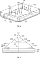
- FIGS. 4-7 show the first inlet header 128A in which the oxidizer flows.
- the first inlet header 128A is optimized for light and efficient fuel cells having a fuel flow path, an oxidizer flow path and a cooling flow path.
- the first inlet header 128A is configured to provide a desired flow rate through the fuel cell 100, produce minimal pressure loss and provide uniform feed to each channel.
- the first inlet header 128A includes an inner end 300 located against the plate stack 110, an outer end 310 spaced apart from the inner end 300, and a plurality of segments 320 between the inner end 300 and the outer end 310.
- the plurality of segments 320 include an outer segment 320A that extends from the outer end 310 to a first intermediate end 330A, defining inlet and outlet ends of the outer segment 320A.
- the outer segment 320A defines a cylindrical profile and is oriented normal to the plate stack 110 and parallel to a direction of flow through the first inlet manifold 122A. That is, the outer segment 320A has a uniform circular cross section between its opposite ends.
- a first intermediate segment 320B forms an outer elbow and extends from the first intermediate end 330A to a second intermediate end 330B, defining the inlet and outlet ends of the first intermediate segment 320B. That is, the first intermediate segment 320B forms a perpendicular bend such that the second intermediate end 330B is closer to the first inlet manifold 122A than the first intermediate end 330A.
- the second intermediate end 330B faces a direction that is perpendicular to the direction of flow through the first outer segment and the inlet manifold 122A and parallel to a direction of channel flow within the plate stack 110. It is to be appreciated that a shape of the inlet end of the first intermediate segment 320B matches that of the first intermediate end 330A.
- the second intermediate end 330B has a rectangular shape rather than a circular shape at the first intermediate end 330A.
- the first intermediate segment 320B increases in width proportionally as it extends toward the second intermediate end 330B. That is, its shape fans out in an elevated view ( FIG. 4 ).
- a second intermediate segment 320C extends from the second intermediate end 330B to a third intermediate end 330C, defining inlet and outlet ends of the second intermediate segment 320C. It is to be appreciated that a shape of the inlet end of the second intermediate segment 320C matches that of the second intermediate end 330B.
- the third intermediate end 330C has a rectangular shape as well.
- the second intermediate segment 320C increases in width and height proportionally as it extends toward the third intermediate end 330C. The proportionality of the increase differs for the width and height in that the height change is less than the width change. That is, the second intermediate segment fans out at a same rate as the first intermediate segment in the elevated view ( FIG. 4 ). Due to the width change, the second intermediate segment 320C forms a trapezoidal profile in an elevated view from the second intermediate end 330B to the third intermediate end 330C.
- An inner segment 320D extends from the third intermediate end 330C to the inner end 300 of the first inlet header 128A, defining inlet and outlet ends of the inner segment 320D.
- the third intermediate end 330C may be smaller than the inlet end of the inner segment 320D to form a dump diffuser.
- the inner segment 320D forms an inner elbow.
- the inner segment 320D forms a perpendicular bend so that its outlet faces a direction that is parallel with the direction of flow through the outer segment and the first inlet manifold 122A. It is to be appreciated that a shape of the outlet end of the inner segment 320D is complementary to that of the first inlet manifold 122A.
- the outer end 310 of the first inlet header 128A defines a header inlet flow area AI and the inner end 300 of the first inlet header 128A defines a header outlet flow area AO ( FIG. 6 ).
- the first intermediate end 330A defines a first flow area A1, the second intermediate end 330B defines a second flow area A2, and the third intermediate end 330C defines a third flow area A3.
- a first ratio of width W2 to height H2 ( FIG. 5 ) of the second flow area A2 may be between 20 and 25, and is preferably 23.
- a second ratio of height H2 of the second flow area to height H3 ( FIG.
- a third flow area A3 may be between 0.25 and 0.75, and is preferably 0.5.
- a third ratio of the second flow area A2 to the first flow area A1 may be between 1.5 and 2, and is preferably 1.8.
- a fourth ratio of the second flow area A2 to the third flow area A3 may be between 3.5 and 4, and is preferably 3.7.
- a fifth ratio of the header outlet flow area AO to the third flow area A3 may be between 1.25 and 1.75, and is preferably 1.5.
- a sixth ratio of the header inlet flow area AI to the header outlet flow area AO may be between 8 and 15, and is preferably 11.
- a seventh ratio of the overall length L, which is measured from the center of A1 to the center of AO, to the inlet header diameter may be between 3 and 7, and is preferably 4.5.
- the first intermediate segment 320B defines first and second sidewalls 320B 1, 320B2.
- An interior angle AN1 is defined between the first and second sidewalls 320B1, 320B2, which may be between 50 and 120 degrees ( FIG. 4 ).
- the second intermediate segment is either smoothly connected to the inner segment or rapidly expanded to the inner segment to form a dump diffuser.
- the second intermediate segment 320C defines third and fourth sidewalls 320C1, 320C2.
- a first set of vanes 340A is defined adjacent to the third sidewall 320C1 and a second set of vanes 340B is defined adjacent to the fourth sidewall 320C2.
- Each of the vanes (generally referenced as 340) defines a walled slot extending through the second intermediate segment 320C. That is, the vanes 340 do not define an opening in the second intermediate segment 320C but rather an internal local flow barrier, e.g., such as internal baffles.
- the vanes 340 may have a same shape as each other. Each of the vanes 340 may define an inner end 350A and an outer end 350B to define a vane length L. The inner end 350A may be closer to the third intermediate end 330C, i.e., the inner segment 320D, than the outer end 350B. An aspect ratio of each of the vanes 340 may be between 3 and 5, and is preferably 4.
- the second intermediate segment 320C may include between 2 and 16 vanes, preferably 8 vanes.
- the vanes 340 are configured symmetrically about a center C extending from the inlet to the outlet of the second intermediate segment 320C. As such, and for simplicity, a discussion of the first set of vanes 340A will apply to the second set of vanes 340B.
- the first set of vanes 340A may be mutually parallel.
- a ratio of spacing S between adjacent vanes 340 to vane length L is between 1 and 3 and is preferably 2.
- the first set of vanes 340 are oriented so that the respective outer ends 350B are closer to the third sidewall 320C1 than the inner ends 350A.
- Each of the vanes 340 defines a pitch angle A2 of between zero and 25 degrees, preferably between zero and 20 degrees, relative to the center C of the second intermediate segment 320C.
- One of the vanes 340A1 in the first set of vanes 340 abuts the third sidewall 320C1 to provide a discontinuity within the second intermediate segment 320C along the third sidewall 320C1. That is, flow in the second intermediate segment 320C will be prevented from flowing continuously against the third sidewall 320C1 from the inlet to the outlet of the second intermediate segment 320C. The resulting angular flow barrier at the third sidewall 320C1 will redirect flow toward the center C, as the flow leaves the second intermediate segment 320C. With less flow against the sidewalls, there will be less drag against the fluid resulting in a lower pressure loss, which results in a reduced loss of the fluid flow rate into and through the fuel cell 100. Within the scope of the embodiments are other flow barrier shapes, such as cylindrical flow barriers instead of slots.
- the first inlet header 128A is configured to provide a desired flow rate through the fuel cell with minimal loss and uniform feed to each channel.
- the design of the first and second intermediate segment, together results in an effective turn of flow without flow separation, reducing pressure loss and recover dynamic head.
- the inlet header has a larger exit to inlet area ratio within a short distance which results in a compact design that optimizes flow into the inlet manifold such that, even with a large number of cell channels, a Mach number of less than 0.3 is typical for the flows.
- the embodiments provide an optimized inlet header for light and efficient fuel cells having a fuel flow path, an oxidizer flow path and a cooling flow path.
Landscapes
- Life Sciences & Earth Sciences (AREA)
- Engineering & Computer Science (AREA)
- Manufacturing & Machinery (AREA)
- Sustainable Development (AREA)
- Sustainable Energy (AREA)
- Chemical & Material Sciences (AREA)
- Chemical Kinetics & Catalysis (AREA)
- Electrochemistry (AREA)
- General Chemical & Material Sciences (AREA)
- Fuel Cell (AREA)
Abstract
Description
- The embodiments related to fuel cells and more specifically to a low loss inlet header for fuel cells.
- A fuel cell is an electrochemical cell that converts the chemical energy of a fuel, such as hydrogen, and an oxidizing agent, such as oxygen, into electricity through chemical reduction-oxidation reactions. For an optimized utilization of light and efficient fuel cells, inlet headers should be configured to produce minimal pressure losses and provide uniform feed to each channel within the fuel cell. In addition, inlet headers and outlets are all located on the same side of fuel cell.
- Disclosed is an inlet header for a fuel cell including: an inner end configured to be located against a plate stack of the fuel cell, an outer end spaced apart from the inner end, and a plurality of segments between the inner end and the outer end, and the plurality of segments include: an outer segment that extends from the outer end to a first intermediate end, wherein the outer segment defines a cylindrical profile; a first intermediate segment that forms an outer elbow and extends from the first intermediate end to a second intermediate end, wherein the second intermediate end has a rectangular shape, and wherein the first intermediate segment increases in width proportionally as it extends toward the second intermediate end; a second intermediate segment that extends from the second intermediate end to a third intermediate end, wherein the third intermediate end has a rectangular shape, and wherein the second intermediate segment increases in width and height proportionally as it extends toward the third intermediate end; and an inner segment that forms an inner elbow and extends from the third intermediate end to the inner end of the inlet header.
- In addition to one or more aspects of the inlet header, or as an alternate, the outer end of the inlet header defines a header inlet flow area; the inner end of the inlet header defines a header outlet flow area; the first intermediate end defines a first flow area; the second intermediate end defines a second flow area; the third intermediate end defines a third flow area; and the inlet header defines one or more of: a first ratio of width to height of the second flow area that is between 20 and 25; a second ratio of height of the second flow area to height of the third flow area that is between 0.25 and 0.75; a third ratio of the second flow area to the first flow area that is between 1.5 and 2; a fourth ratio of the second flow area to the third flow area that is between 3.5 and 4; a fifth ratio of the header outlet flow area to the third flow area that is between 1.25 and 1.75; a sixth ratio of the header inlet flow area to the header outlet flow area that is between 8 and 15; or a seventh ratio of an overall length of the inlet header to the inlet header diameter that is between 3 and 7.
- In addition to one or more aspects of the inlet header, or as an alternate, the first intermediate segment defines first and second sidewalls; and an interior angle defined between the first and second sidewalls is between 50 and 120 degrees.
- In addition to one or more aspects of the inlet header, or as an alternate, the second intermediate segment defines third and fourth sidewalls; and near the third intermediate end of the second intermediate segment, a first set of vanes is formed adjacent to the third sidewall and a second set of vanes is formed adjacent to the fourth sidewall, each of vanes defining a walled slot extending through the second intermediate segment.
- In addition to one or more aspects of the inlet header, or as an alternate, the vanes have a same shape as each other; and each of the vanes defines an inner end and an outer end to define a vane length, wherein the inner end is closer to the third intermediate end than the outer end.
- In addition to one or more aspects of the inlet header, or as an alternate, an aspect ratio of each of the vanes is between 3 and 5.
- In addition to one or more aspects of the inlet header, or as an alternate, the vanes are configured symmetrically about a center of the second intermediate segment.
- In addition to one or more aspects of the inlet header, or as an alternate, the first set of vanes are mutually parallel.
- In addition to one or more aspects of the inlet header, or as an alternate, within the first set of vanes, a ratio of spacing between adjacent ones of the vanes to the vane length is between 1 and 3.
- In addition to one or more aspects of the inlet header, or as an alternate, the first set of vanes are oriented so that the respective outer ends are closer to the third sidewall than the inner ends.
- In addition to one or more aspects of the inlet header, or as an alternate, each of the vanes defines a pitch angle of between 0 and 25 degrees relative to the center of the second intermediate segment.
- In addition to one or more aspects of the inlet header, or as an alternate, one of the vanes in the first set of vanes abuts the third sidewall to provide a discontinuity within the second intermediate segment along the third sidewall.
- In addition to one or more aspects of the inlet header, or as an alternate, the second intermediate segment includes between 2 and 16 of the vanes.
- Disclosed is a fuel cell, including: a bipolar plate stack that has a first end and defines a first inlet manifold; and an inlet header having one or more of the above disclosed aspects.
- In addition to one or more aspects of the fuel cell, or as an alternate, the inlet header is a first inlet header, and the plate stack defines a first outlet manifold that is fluidly coupled to the first inlet manifold to define a first flow circuit, wherein the first outlet manifold includes a first outlet that is located against the first end of the plate stack.
- In addition to one or more aspects of the fuel cell, or as an alternate, the first flow circuit includes an oxidizer.
- In addition to one or more aspects of the fuel cell, or as an alternate, the oxidizer is air or oxygen.
- In addition to one or more aspects of the fuel cell, or as an alternate, the plate stack defines: a second inlet manifold and a second outlet manifold that are fluidly coupled with each other to define a second flow circuit that includes hydrogen, wherein the second inlet manifold includes a second inlet header and the second outlet manifold includes a second outlet; and a third inlet manifold and a third outlet manifold that are fluidly coupled with each other to define a third flow circuit that includes water, wherein the third inlet manifold includes a third inlet header and the third outlet manifold includes a third outlet.
- In addition to one or more aspects of the fuel cell, or as an alternate, each of the manifolds is disposed against the first end of the plate stack, and a header end plate is disposed against the first end of the plate stack and surrounds each of the inlet headers and outlets.
- In addition to one or more aspects of the fuel cell, or as an alternate, the plate stack includes adjacently disposed plates, each of the plates defining an inlet manifold orifice and an outlet manifold orifice, and cell channels that are fluidly coupled to one of the flow circuits and fluidly isolated from the other ones of the flow circuits.
- The following descriptions should not be considered limiting in any way. With reference to the accompanying drawings, like elements are numbered alike:
-
FIG. 1 shows a plate of the fuel cell stack; -
FIG. 2 shows the fluid flow paths through the plates of the fuel cell stack and through header inlets and outlets; -
FIG. 3 shows an end plate against one end of the plate stack that encloses the header inlets and outlets; -
FIG. 4 shows an elevational view of the first inlet header; -
FIG. 5 shows a first intermediate segment of the first inlet header; -
FIG. 6 shows a side view of the first inlet header; -
FIG. 7 shows another side view of the first inlet header; and -
FIG. 8 shows a detail ofFIG. 4 , showing vanes utilized in the first inlet header. - A detailed description of one or more embodiments of the disclosed apparatus and method are presented herein by way of exemplification and not limitation with reference to the Figures.
- Regarding the figures, it should be noted that that
FIG. 1 shows hardware, whileFIGS. 2 to 8 show a space that fluid occupies, e.g., a fluid flow path within the hardware. Turning now toFIGS. 1-3 , these figures generally show afuel cell 100 according to an embodiment. As shown inFIG. 1 , thefuel cell 100 includes a bipolar plate stack, or plate stack 110. The plate stack 110 includesplates 120, eachplate 120 definescell channels 121, which are grooves in a plane of aplate 120. Eachplate 120 also defines aninlet manifold orifice 123 and anoutlet manifold orifice 125. In the plate stack 110, the inlet andoutlet manifold orifices outlet manifolds cell channels 121 on certain ones of the plates. - Turning to
FIG. 2 , thecell stack 100 definesflow circuits 126, which are fluidly coupledinlet manifolds 122,outlet manifolds 124 andcell channels 121. Eachflow circuit 126 has aninlet header 128 fluidly coupled to itsinlet manifold 122 and anoutlet 129 fluidly coupled to itsoutlet manifold 124. It should be appreciated thatFIG. 2 shows the resulting fluid flow through the plates of thefuel cell 100 rather than the plate stack 110. - More specifically, the plate stack 110 defines a first inlet manifold 122A and a first outlet manifold 124A that are fluidly coupled to each other to define a first flow circuit 126A that includes an oxidizer, which may be air or oxygen. A first inlet header 128A is fluidly coupled to the first inlet manifold 122A and a first outlet 129A is fluidly coupled to the first outlet manifold 124A. The plate stack 110 defines a second inlet manifold 122B and a second outlet manifold 124B that are fluidly coupled with each other to define a second flow circuit 126B that includes fuel, which may be hydrogen. The second inlet manifold 122B is fluidly coupled to a second inlet header 128B and the second outlet manifold 124B is fluidly coupled to a second outlet 129B. The plate stack 110 defines a third inlet manifold 122C and a third outlet manifold 124C that are fluidly coupled with each other to define a third flow circuit 126C, that includes water. The third inlet manifold 122C is fluidly coupled to a third inlet header 128C and the third outlet manifold 124C is fluidly coupled to a third outlet 129C.
- As shown in
FIG. 3 , each of theinlet headers 128 andoutlets 129 are disposed against afirst end 140 of the plate stack 110. Aheader end plate 115, disposed against thefirst end 140 of the plate stack 110, surrounds each of theinlet headers 128 andoutlets 129. -
FIGS. 4-7 show the first inlet header 128A in which the oxidizer flows. The first inlet header 128A is optimized for light and efficient fuel cells having a fuel flow path, an oxidizer flow path and a cooling flow path. The first inlet header 128A is configured to provide a desired flow rate through thefuel cell 100, produce minimal pressure loss and provide uniform feed to each channel. - More specifically, the first inlet header 128A includes an
inner end 300 located against the plate stack 110, anouter end 310 spaced apart from theinner end 300, and a plurality ofsegments 320 between theinner end 300 and theouter end 310. - The plurality of
segments 320 include anouter segment 320A that extends from theouter end 310 to a firstintermediate end 330A, defining inlet and outlet ends of theouter segment 320A. Theouter segment 320A defines a cylindrical profile and is oriented normal to the plate stack 110 and parallel to a direction of flow through the first inlet manifold 122A. That is, theouter segment 320A has a uniform circular cross section between its opposite ends. - A first
intermediate segment 320B forms an outer elbow and extends from the firstintermediate end 330A to a secondintermediate end 330B, defining the inlet and outlet ends of the firstintermediate segment 320B. That is, the firstintermediate segment 320B forms a perpendicular bend such that the secondintermediate end 330B is closer to the first inlet manifold 122A than the firstintermediate end 330A. The secondintermediate end 330B faces a direction that is perpendicular to the direction of flow through the first outer segment and the inlet manifold 122A and parallel to a direction of channel flow within the plate stack 110. It is to be appreciated that a shape of the inlet end of the firstintermediate segment 320B matches that of the firstintermediate end 330A. The secondintermediate end 330B has a rectangular shape rather than a circular shape at the firstintermediate end 330A. The firstintermediate segment 320B increases in width proportionally as it extends toward the secondintermediate end 330B. That is, its shape fans out in an elevated view (FIG. 4 ). - A second
intermediate segment 320C extends from the secondintermediate end 330B to a thirdintermediate end 330C, defining inlet and outlet ends of the secondintermediate segment 320C. It is to be appreciated that a shape of the inlet end of the secondintermediate segment 320C matches that of the secondintermediate end 330B. The thirdintermediate end 330C has a rectangular shape as well. The secondintermediate segment 320C increases in width and height proportionally as it extends toward the thirdintermediate end 330C. The proportionality of the increase differs for the width and height in that the height change is less than the width change. That is, the second intermediate segment fans out at a same rate as the first intermediate segment in the elevated view (FIG. 4 ). Due to the width change, the secondintermediate segment 320C forms a trapezoidal profile in an elevated view from the secondintermediate end 330B to the thirdintermediate end 330C. - An
inner segment 320D extends from the thirdintermediate end 330C to theinner end 300 of the first inlet header 128A, defining inlet and outlet ends of theinner segment 320D. The thirdintermediate end 330C may be smaller than the inlet end of theinner segment 320D to form a dump diffuser. Theinner segment 320D forms an inner elbow. Theinner segment 320D forms a perpendicular bend so that its outlet faces a direction that is parallel with the direction of flow through the outer segment and the first inlet manifold 122A. It is to be appreciated that a shape of the outlet end of theinner segment 320D is complementary to that of the first inlet manifold 122A. - Regarding geometric relationships of the inlet header segments, the
outer end 310 of the first inlet header 128A defines a header inlet flow area AI and theinner end 300 of the first inlet header 128A defines a header outlet flow area AO (FIG. 6 ). The firstintermediate end 330A defines a first flow area A1, the secondintermediate end 330B defines a second flow area A2, and the thirdintermediate end 330C defines a third flow area A3. According to an embodiment, a first ratio of width W2 to height H2 (FIG. 5 ) of the second flow area A2 may be between 20 and 25, and is preferably 23. A second ratio of height H2 of the second flow area to height H3 (FIG. 6 ) of the third flow area A3 may be between 0.25 and 0.75, and is preferably 0.5. A third ratio of the second flow area A2 to the first flow area A1 may be between 1.5 and 2, and is preferably 1.8. A fourth ratio of the second flow area A2 to the third flow area A3 may be between 3.5 and 4, and is preferably 3.7. A fifth ratio of the header outlet flow area AO to the third flow area A3 may be between 1.25 and 1.75, and is preferably 1.5. A sixth ratio of the header inlet flow area AI to the header outlet flow area AO may be between 8 and 15, and is preferably 11. A seventh ratio of the overall length L, which is measured from the center of A1 to the center of AO, to the inlet header diameter may be between 3 and 7, and is preferably 4.5. In one embodiment, the firstintermediate segment 320B defines first andsecond sidewalls 320BFIG. 4 ). As shown and described herein, the second intermediate segment is either smoothly connected to the inner segment or rapidly expanded to the inner segment to form a dump diffuser. - As shown in
FIG. 4 , according to the illustrated embodiment, the secondintermediate segment 320C defines third and fourth sidewalls 320C1, 320C2. Near the thirdintermediate end 330C of the secondintermediate segment 320C, a first set ofvanes 340A is defined adjacent to the third sidewall 320C1 and a second set of vanes 340B is defined adjacent to the fourth sidewall 320C2. Each of the vanes (generally referenced as 340) defines a walled slot extending through the secondintermediate segment 320C. That is, thevanes 340 do not define an opening in the secondintermediate segment 320C but rather an internal local flow barrier, e.g., such as internal baffles. - The
vanes 340 may have a same shape as each other. Each of thevanes 340 may define aninner end 350A and anouter end 350B to define a vane length L. Theinner end 350A may be closer to the thirdintermediate end 330C, i.e., theinner segment 320D, than theouter end 350B. An aspect ratio of each of thevanes 340 may be between 3 and 5, and is preferably 4. The secondintermediate segment 320C may include between 2 and 16 vanes, preferably 8 vanes. - In the illustrated embodiment, the
vanes 340 are configured symmetrically about a center C extending from the inlet to the outlet of the secondintermediate segment 320C. As such, and for simplicity, a discussion of the first set ofvanes 340A will apply to the second set of vanes 340B. - Turning to
FIG. 8 , the first set ofvanes 340A may be mutually parallel. Within the first set ofvanes 340A, a ratio of spacing S betweenadjacent vanes 340 to vane length L is between 1 and 3 and is preferably 2. The first set ofvanes 340 are oriented so that the respective outer ends 350B are closer to the third sidewall 320C1 than the inner ends 350A. Each of thevanes 340 defines a pitch angle A2 of between zero and 25 degrees, preferably between zero and 20 degrees, relative to the center C of the secondintermediate segment 320C. One of the vanes 340A1 in the first set ofvanes 340 abuts the third sidewall 320C1 to provide a discontinuity within the secondintermediate segment 320C along the third sidewall 320C1. That is, flow in the secondintermediate segment 320C will be prevented from flowing continuously against the third sidewall 320C1 from the inlet to the outlet of the secondintermediate segment 320C. The resulting angular flow barrier at the third sidewall 320C1 will redirect flow toward the center C, as the flow leaves the secondintermediate segment 320C. With less flow against the sidewalls, there will be less drag against the fluid resulting in a lower pressure loss, which results in a reduced loss of the fluid flow rate into and through thefuel cell 100. Within the scope of the embodiments are other flow barrier shapes, such as cylindrical flow barriers instead of slots. - With the above ratios, angles, and vanes, the first inlet header 128A is configured to provide a desired flow rate through the fuel cell with minimal loss and uniform feed to each channel. For example, the design of the first and second intermediate segment, together, results in an effective turn of flow without flow separation, reducing pressure loss and recover dynamic head. The inlet header has a larger exit to inlet area ratio within a short distance which results in a compact design that optimizes flow into the inlet manifold such that, even with a large number of cell channels, a Mach number of less than 0.3 is typical for the flows. Thus, the embodiments provide an optimized inlet header for light and efficient fuel cells having a fuel flow path, an oxidizer flow path and a cooling flow path.
- The terminology used herein is for the purpose of describing particular embodiments only and is not intended to be limiting of the present disclosure. As used herein, the singular forms "a", "an" and "the" are intended to include the plural forms as well, unless the context clearly indicates otherwise. It will be further understood that the terms "comprises" and/or "comprising," when used in this specification, specify the presence of stated features, integers, steps, operations, elements, and/or components, but do not preclude the presence or addition of one or more other features, integers, steps, operations, element components, and/or groups thereof.
- Those of skill in the art will appreciate that various example embodiments are shown and described herein, each having certain features in the particular embodiments, but the present disclosure is not thus limited. Rather, the present disclosure can be modified to incorporate any number of variations, alterations, substitutions, combinations, sub-combinations, or equivalent arrangements not heretofore described, but which are commensurate with the scope of the present disclosure. Additionally, while various embodiments of the present disclosure have been described, it is to be understood that aspects of the present disclosure may include only some of the described embodiments. Accordingly, the present disclosure is not to be seen as limited by the foregoing description, but is only limited by the scope of the appended claims.
Claims (15)
- An inlet header (128A) for a fuel cell comprising:
an inner end configured to be located against a plate stack of the fuel cell, an outer end spaced apart from the inner end, and a plurality of segments between the inner end and the outer end, and the plurality of segments include:an outer segment (320A) that extends from the outer end to a first intermediate end, wherein the outer segment (320A) defines a cylindrical profile;a first intermediate segment (320B) that forms an outer elbow and extends from the first intermediate end to a second intermediate end, wherein the second intermediate end has a rectangular shape, and wherein the first intermediate segment (320B) increases in width proportionally as it extends toward the second intermediate end;a second intermediate segment (320C) that extends from the second intermediate end to a third intermediate end, wherein the third intermediate end has a rectangular shape, and wherein the second intermediate segment (320C) increases in width and height proportionally as it extends toward the third intermediate end; andan inner segment that forms an inner elbow and extends from the third intermediate end to the inner end of the inlet header (128A). - The inlet header (128A) of claim 1, wherein:the outer end of the inlet header (128A) defines a header inlet flow area;the inner end of the inlet header (128A) defines a header outlet flow area;the first intermediate end defines a first flow area;the second intermediate end defines a second flow area;the third intermediate end defines a third flow area; andthe inlet header (128A) defines one or more of:a first ratio of width to height of the second flow area that is between 20 and 25;a second ratio of height of the second flow area to height of the third flow area that is between 0.25 and 0.75;a third ratio of the second flow area to the first flow area that is between 1.5 and 2;a fourth ratio of the second flow area to the third flow area that is between 3.5 and 4;a fifth ratio of the header outlet flow area to the third flow area that is between 1.25 and 1.75;a sixth ratio of the header inlet flow area to the header outlet flow area that is between 8 and 15; ora seventh ratio of an overall length of the inlet header (128A) to the inlet header diameter that is between 3 and 7.
- The inlet header (128A) of claim 1 or 2, wherein:the first intermediate segment (320B) defines first and second sidewalls; andan interior angle defined between the first and second sidewalls is between 50 and 120 degrees.
- The inlet header (128A) of claim 3, wherein:the second intermediate segment (320C) defines third and fourth sidewalls; andnear the third intermediate end of the second intermediate segment (320C), a first set of vanes is formed adjacent to the third sidewall and a second set of vanes is formed adjacent to the fourth sidewall, each of vanes defining a walled slot extending through the second intermediate segment (320C).
- The inlet header (128A) of claim 4, wherein:the vanes have a same shape as each other; andeach of the vanes defines an inner end and an outer end to define a vane length, wherein the inner end is closer to the third intermediate end than the outer end.
- The inlet header (128A) of claim 5, whereinan aspect ratio of each of the vanes is between 3 and 5, and/or whereinthe vanes are configured symmetrically about a center of the second intermediate segment (320C).
- The inlet header (128A) of claim 6, wherein
the first set of vanes are mutually parallel. - The inlet header (128A) of claim 6, wherein
within the first set of vanes, a ratio of spacing between adjacent ones of the vanes to the vane length is between 1 and 3, and/or wherein:
the first set of vanes are oriented so that the respective outer ends are closer to the third sidewall than the inner ends. - The inlet header (128A) of claim 6, wherein:each of the vanes defines a pitch angle of between 0 and 25 degrees relative to the center of the second intermediate segment (320C), and/or wherein:
one of the vanes in the first set of vanes abuts the third sidewall to provide a discontinuity within the second intermediate segment (320C) along the third sidewall, and/orwherein:
the second intermediate segment (320C) includes between 2 and 16 of the vanes. - A fuel cell, comprising:a bipolar plate stack that has a first end and defines a first inlet manifold; andthe inlet header (128A) of claim 1.
- The fuel cell of claim 10, wherein:the inlet header (128A) is a first inlet header, andthe plate stack defines a first outlet manifold that is fluidly coupled to the first inlet manifold to define a first flow circuit, wherein the first outlet manifold includes a first outlet that is located against the first end of the plate stack.
- The fuel cell of any of claims 10 or 11, wherein:
the first flow circuit includes an oxidizer. - The fuel cell of any of claims 10 to 12, wherein
the oxidizer is air or oxygen. - The fuel cell of any of claims 10 to 13, wherein
the plate stack defines:a second inlet manifold and a second outlet manifold that are fluidly coupled with each other to define a second flow circuit that includes hydrogen, wherein the second inlet manifold includes a second inlet header and the second outlet manifold includes a second outlet; anda third inlet manifold and a third outlet manifold that are fluidly coupled with each other to define a third flow circuit that includes water, wherein the third inlet manifold includes a third inlet header and the third outlet manifold includes a third outlet. - The fuel cell of claim 14, whereineach of the manifolds is disposed against the first end of the plate stack, and a header end plate is disposed against the first end of the plate stack and surrounds each of the inlet headers and outlets, and optionally whereinthe plate stack includes adjacently disposed plates, each of the plates defining an inlet manifold orifice and an outlet manifold orifice, and cell channels that are fluidly coupled to one of the flow circuits and fluidly isolated from the other ones of the flow circuits.
Applications Claiming Priority (1)
| Application Number | Priority Date | Filing Date | Title |
|---|---|---|---|
| US17/714,334 US11923585B2 (en) | 2022-04-06 | 2022-04-06 | Low loss inlet header for fuel cells |
Publications (2)
| Publication Number | Publication Date |
|---|---|
| EP4276957A1 true EP4276957A1 (en) | 2023-11-15 |
| EP4276957B1 EP4276957B1 (en) | 2025-05-28 |
Family
ID=85703857
Family Applications (1)
| Application Number | Title | Priority Date | Filing Date |
|---|---|---|---|
| EP23162137.6A Active EP4276957B1 (en) | 2022-04-06 | 2023-03-15 | Low loss inlet header for fuel cells |
Country Status (4)
| Country | Link |
|---|---|
| US (1) | US11923585B2 (en) |
| EP (1) | EP4276957B1 (en) |
| KR (1) | KR20230143942A (en) |
| CN (1) | CN116895815A (en) |
Families Citing this family (1)
| Publication number | Priority date | Publication date | Assignee | Title |
|---|---|---|---|---|
| CN119084689B (en) * | 2024-07-30 | 2025-12-19 | 东风汽车集团股份有限公司 | Runner switching structure, fuel cell stack and vehicle |
Citations (3)
| Publication number | Priority date | Publication date | Assignee | Title |
|---|---|---|---|---|
| US6179342B1 (en) * | 1999-06-11 | 2001-01-30 | Hsin-Der Shen | Bend conduit having low pressure loss coefficient |
| US20030118878A1 (en) * | 2001-10-19 | 2003-06-26 | Pinto Martin De Tezanos | Manifold for fuel cell system |
| US20140234743A1 (en) * | 2013-02-18 | 2014-08-21 | Honda Motor Co., Ltd. | Fuel cell stack |
Family Cites Families (6)
| Publication number | Priority date | Publication date | Assignee | Title |
|---|---|---|---|---|
| US20050118487A1 (en) | 2003-12-02 | 2005-06-02 | Whiton John H. | Small volume, fuel cell inlet fuel gas distributor having low pressure drop |
| KR100722411B1 (en) | 2005-09-02 | 2007-05-28 | 지에스퓨얼셀 주식회사 | Manifold of Fuel Cell Stack |
| US9105915B2 (en) * | 2009-01-26 | 2015-08-11 | Honda Motor Co., Ltd. | Fuel cell stack coupled to a humidifier via an inclined channel |
| US8679696B2 (en) | 2010-03-17 | 2014-03-25 | GM Global Technology Operations LLC | PEM fuel cell stack hydrogen distribution insert |
| GB2482186A (en) | 2010-07-23 | 2012-01-25 | Dale Mcphee Purcocks | Waterproof keyboard |
| JP5593937B2 (en) * | 2010-08-05 | 2014-09-24 | トヨタ自動車株式会社 | Fuel cell device |
-
2022
- 2022-04-06 US US17/714,334 patent/US11923585B2/en active Active
-
2023
- 2023-03-15 EP EP23162137.6A patent/EP4276957B1/en active Active
- 2023-03-24 CN CN202310300950.5A patent/CN116895815A/en active Pending
- 2023-04-03 KR KR1020230043354A patent/KR20230143942A/en active Pending
Patent Citations (3)
| Publication number | Priority date | Publication date | Assignee | Title |
|---|---|---|---|---|
| US6179342B1 (en) * | 1999-06-11 | 2001-01-30 | Hsin-Der Shen | Bend conduit having low pressure loss coefficient |
| US20030118878A1 (en) * | 2001-10-19 | 2003-06-26 | Pinto Martin De Tezanos | Manifold for fuel cell system |
| US20140234743A1 (en) * | 2013-02-18 | 2014-08-21 | Honda Motor Co., Ltd. | Fuel cell stack |
Also Published As
| Publication number | Publication date |
|---|---|
| US11923585B2 (en) | 2024-03-05 |
| KR20230143942A (en) | 2023-10-13 |
| EP4276957B1 (en) | 2025-05-28 |
| US20230327169A1 (en) | 2023-10-12 |
| CN116895815A (en) | 2023-10-17 |
Similar Documents
| Publication | Publication Date | Title |
|---|---|---|
| US6794068B2 (en) | Fuel cell stack design and method of operation | |
| US9528778B2 (en) | Refrigerant guiding pipe and heat exchanger having refrigerant guiding pipe | |
| EP4276957B1 (en) | Low loss inlet header for fuel cells | |
| US8802311B2 (en) | Fuel cell stack structure | |
| KR102416327B1 (en) | Apparatus comprising a fuel cell unit and a component, a component unit and a stack component for use in such an apparatus | |
| FI130318B (en) | A shell and tube heat exchanger | |
| US20200075966A1 (en) | Separator for fuel cell including guide pattern and fuel cell stack including the same | |
| US20080226963A1 (en) | Flow field plate module for fuel cell system | |
| AU2016221799B2 (en) | Shell and tube heat exchanger having sequentially arranged shell and tube components | |
| US9506483B2 (en) | Fluid tube increasing uniformity of fluid flow and apparatus including the same | |
| CN118402100A (en) | Bipolar plate for fuel cell stack | |
| US7258081B2 (en) | Compact water vaporizer for dynamic steam generation and uniform temperature control | |
| CN112310430A (en) | A fuel cell bipolar plate based on Dean eddy current field and its use | |
| CN115275248A (en) | Fuel cell and bipolar plate assembly thereof | |
| KR20240033490A (en) | Separator for feul cell | |
| CN117393827A (en) | Flow distribution plate and battery system | |
| TW200901540A (en) | Flow channel plate | |
| US12633549B2 (en) | Separator for fuel cell | |
| EP4354557B1 (en) | Separator for fuel cell | |
| CN217518918U (en) | Air compression device and hydrogen energy system | |
| CN114797517B (en) | Gas mixing device | |
| CN116404197B (en) | Spray evaporation cavity with humidifier and intercooler functions and system thereof | |
| US11404705B2 (en) | Bipolar plate of polymer electrolyte membrane fuel cell | |
| CN117393826A (en) | Flow distribution plate and battery system | |
| CN116581351A (en) | Reactant feed and return assemblies for fuel cell stacks including nozzle arrangements |
Legal Events
| Date | Code | Title | Description |
|---|---|---|---|
| PUAI | Public reference made under article 153(3) epc to a published international application that has entered the european phase |
Free format text: ORIGINAL CODE: 0009012 |
|
| STAA | Information on the status of an ep patent application or granted ep patent |
Free format text: STATUS: THE APPLICATION HAS BEEN PUBLISHED |
|
| AK | Designated contracting states |
Kind code of ref document: A1 Designated state(s): AL AT BE BG CH CY CZ DE DK EE ES FI FR GB GR HR HU IE IS IT LI LT LU LV MC ME MK MT NL NO PL PT RO RS SE SI SK SM TR |
|
| STAA | Information on the status of an ep patent application or granted ep patent |
Free format text: STATUS: REQUEST FOR EXAMINATION WAS MADE |
|
| 17P | Request for examination filed |
Effective date: 20240513 |
|
| RBV | Designated contracting states (corrected) |
Designated state(s): AL AT BE BG CH CY CZ DE DK EE ES FI FR GB GR HR HU IE IS IT LI LT LU LV MC ME MK MT NL NO PL PT RO RS SE SI SK SM TR |
|
| GRAP | Despatch of communication of intention to grant a patent |
Free format text: ORIGINAL CODE: EPIDOSNIGR1 |
|
| STAA | Information on the status of an ep patent application or granted ep patent |
Free format text: STATUS: GRANT OF PATENT IS INTENDED |
|
| INTG | Intention to grant announced |
Effective date: 20241220 |
|
| GRAS | Grant fee paid |
Free format text: ORIGINAL CODE: EPIDOSNIGR3 |
|
| GRAA | (expected) grant |
Free format text: ORIGINAL CODE: 0009210 |
|
| STAA | Information on the status of an ep patent application or granted ep patent |
Free format text: STATUS: THE PATENT HAS BEEN GRANTED |
|
| AK | Designated contracting states |
Kind code of ref document: B1 Designated state(s): AL AT BE BG CH CY CZ DE DK EE ES FI FR GB GR HR HU IE IS IT LI LT LU LV MC ME MK MT NL NO PL PT RO RS SE SI SK SM TR |
|
| REG | Reference to a national code |
Ref country code: GB Ref legal event code: FG4D |
|
| REG | Reference to a national code |
Ref country code: CH Ref legal event code: EP |
|
| REG | Reference to a national code |
Ref country code: DE Ref legal event code: R096 Ref document number: 602023003661 Country of ref document: DE |
|
| REG | Reference to a national code |
Ref country code: IE Ref legal event code: FG4D |
|
| REG | Reference to a national code |
Ref country code: NL Ref legal event code: MP Effective date: 20250528 |
|
| PG25 | Lapsed in a contracting state [announced via postgrant information from national office to epo] |
Ref country code: FI Free format text: LAPSE BECAUSE OF FAILURE TO SUBMIT A TRANSLATION OF THE DESCRIPTION OR TO PAY THE FEE WITHIN THE PRESCRIBED TIME-LIMIT Effective date: 20250528 Ref country code: ES Free format text: LAPSE BECAUSE OF FAILURE TO SUBMIT A TRANSLATION OF THE DESCRIPTION OR TO PAY THE FEE WITHIN THE PRESCRIBED TIME-LIMIT Effective date: 20250528 |
|
| REG | Reference to a national code |
Ref country code: LT Ref legal event code: MG9D |
|
| PG25 | Lapsed in a contracting state [announced via postgrant information from national office to epo] |
Ref country code: GR Free format text: LAPSE BECAUSE OF FAILURE TO SUBMIT A TRANSLATION OF THE DESCRIPTION OR TO PAY THE FEE WITHIN THE PRESCRIBED TIME-LIMIT Effective date: 20250829 Ref country code: NO Free format text: LAPSE BECAUSE OF FAILURE TO SUBMIT A TRANSLATION OF THE DESCRIPTION OR TO PAY THE FEE WITHIN THE PRESCRIBED TIME-LIMIT Effective date: 20250828 |
|
| PG25 | Lapsed in a contracting state [announced via postgrant information from national office to epo] |
Ref country code: PL Free format text: LAPSE BECAUSE OF FAILURE TO SUBMIT A TRANSLATION OF THE DESCRIPTION OR TO PAY THE FEE WITHIN THE PRESCRIBED TIME-LIMIT Effective date: 20250528 Ref country code: NL Free format text: LAPSE BECAUSE OF FAILURE TO SUBMIT A TRANSLATION OF THE DESCRIPTION OR TO PAY THE FEE WITHIN THE PRESCRIBED TIME-LIMIT Effective date: 20250528 |
|
| PG25 | Lapsed in a contracting state [announced via postgrant information from national office to epo] |
Ref country code: BG Free format text: LAPSE BECAUSE OF FAILURE TO SUBMIT A TRANSLATION OF THE DESCRIPTION OR TO PAY THE FEE WITHIN THE PRESCRIBED TIME-LIMIT Effective date: 20250528 |
|
| PG25 | Lapsed in a contracting state [announced via postgrant information from national office to epo] |
Ref country code: HR Free format text: LAPSE BECAUSE OF FAILURE TO SUBMIT A TRANSLATION OF THE DESCRIPTION OR TO PAY THE FEE WITHIN THE PRESCRIBED TIME-LIMIT Effective date: 20250528 |
|
| PG25 | Lapsed in a contracting state [announced via postgrant information from national office to epo] |
Ref country code: RS Free format text: LAPSE BECAUSE OF FAILURE TO SUBMIT A TRANSLATION OF THE DESCRIPTION OR TO PAY THE FEE WITHIN THE PRESCRIBED TIME-LIMIT Effective date: 20250828 |
|
| PG25 | Lapsed in a contracting state [announced via postgrant information from national office to epo] |
Ref country code: IS Free format text: LAPSE BECAUSE OF FAILURE TO SUBMIT A TRANSLATION OF THE DESCRIPTION OR TO PAY THE FEE WITHIN THE PRESCRIBED TIME-LIMIT Effective date: 20250928 |
|
| PG25 | Lapsed in a contracting state [announced via postgrant information from national office to epo] |
Ref country code: LV Free format text: LAPSE BECAUSE OF FAILURE TO SUBMIT A TRANSLATION OF THE DESCRIPTION OR TO PAY THE FEE WITHIN THE PRESCRIBED TIME-LIMIT Effective date: 20250528 |
|
| REG | Reference to a national code |
Ref country code: AT Ref legal event code: MK05 Ref document number: 1799172 Country of ref document: AT Kind code of ref document: T Effective date: 20250528 |
|
| PG25 | Lapsed in a contracting state [announced via postgrant information from national office to epo] |
Ref country code: SM Free format text: LAPSE BECAUSE OF FAILURE TO SUBMIT A TRANSLATION OF THE DESCRIPTION OR TO PAY THE FEE WITHIN THE PRESCRIBED TIME-LIMIT Effective date: 20250528 Ref country code: DK Free format text: LAPSE BECAUSE OF FAILURE TO SUBMIT A TRANSLATION OF THE DESCRIPTION OR TO PAY THE FEE WITHIN THE PRESCRIBED TIME-LIMIT Effective date: 20250528 Ref country code: AT Free format text: LAPSE BECAUSE OF FAILURE TO SUBMIT A TRANSLATION OF THE DESCRIPTION OR TO PAY THE FEE WITHIN THE PRESCRIBED TIME-LIMIT Effective date: 20250528 |
|
| PG25 | Lapsed in a contracting state [announced via postgrant information from national office to epo] |
Ref country code: CZ Free format text: LAPSE BECAUSE OF FAILURE TO SUBMIT A TRANSLATION OF THE DESCRIPTION OR TO PAY THE FEE WITHIN THE PRESCRIBED TIME-LIMIT Effective date: 20250528 |
|
| PG25 | Lapsed in a contracting state [announced via postgrant information from national office to epo] |
Ref country code: EE Free format text: LAPSE BECAUSE OF FAILURE TO SUBMIT A TRANSLATION OF THE DESCRIPTION OR TO PAY THE FEE WITHIN THE PRESCRIBED TIME-LIMIT Effective date: 20250528 |
|
| PG25 | Lapsed in a contracting state [announced via postgrant information from national office to epo] |
Ref country code: SK Free format text: LAPSE BECAUSE OF FAILURE TO SUBMIT A TRANSLATION OF THE DESCRIPTION OR TO PAY THE FEE WITHIN THE PRESCRIBED TIME-LIMIT Effective date: 20250528 |
|
| PG25 | Lapsed in a contracting state [announced via postgrant information from national office to epo] |
Ref country code: IT Free format text: LAPSE BECAUSE OF FAILURE TO SUBMIT A TRANSLATION OF THE DESCRIPTION OR TO PAY THE FEE WITHIN THE PRESCRIBED TIME-LIMIT Effective date: 20250528 |
|
| REG | Reference to a national code |
Ref country code: DE Ref legal event code: R097 Ref document number: 602023003661 Country of ref document: DE |
|
| PLBE | No opposition filed within time limit |
Free format text: ORIGINAL CODE: 0009261 |
|
| STAA | Information on the status of an ep patent application or granted ep patent |
Free format text: STATUS: NO OPPOSITION FILED WITHIN TIME LIMIT |
|
| REG | Reference to a national code |
Ref country code: CH Ref legal event code: L10 Free format text: ST27 STATUS EVENT CODE: U-0-0-L10-L00 (AS PROVIDED BY THE NATIONAL OFFICE) Effective date: 20260409 |
|
| 26N | No opposition filed |
Effective date: 20260303 |