EP4276934A1 - Positive electrode plate and lithium ion battery containing electrode plate - Google Patents
Positive electrode plate and lithium ion battery containing electrode plate Download PDFInfo
- Publication number
- EP4276934A1 EP4276934A1 EP22922812.7A EP22922812A EP4276934A1 EP 4276934 A1 EP4276934 A1 EP 4276934A1 EP 22922812 A EP22922812 A EP 22922812A EP 4276934 A1 EP4276934 A1 EP 4276934A1
- Authority
- EP
- European Patent Office
- Prior art keywords
- positive electrode
- lithium
- active material
- electrode active
- layer
- Prior art date
- Legal status (The legal status is an assumption and is not a legal conclusion. Google has not performed a legal analysis and makes no representation as to the accuracy of the status listed.)
- Pending
Links
- HBBGRARXTFLTSG-UHFFFAOYSA-N Lithium ion Chemical compound [Li+] HBBGRARXTFLTSG-UHFFFAOYSA-N 0.000 title claims abstract description 60
- 229910001416 lithium ion Inorganic materials 0.000 title claims abstract description 60
- 238000006138 lithiation reaction Methods 0.000 claims abstract description 64
- WHXSMMKQMYFTQS-UHFFFAOYSA-N Lithium Chemical compound [Li] WHXSMMKQMYFTQS-UHFFFAOYSA-N 0.000 claims abstract description 24
- 229910052744 lithium Inorganic materials 0.000 claims abstract description 24
- 239000007774 positive electrode material Substances 0.000 claims description 102
- 239000002245 particle Substances 0.000 claims description 67
- 239000003795 chemical substances by application Substances 0.000 claims description 51
- 239000006258 conductive agent Substances 0.000 claims description 49
- 239000011230 binding agent Substances 0.000 claims description 37
- XEEYBQQBJWHFJM-UHFFFAOYSA-N Iron Chemical compound [Fe] XEEYBQQBJWHFJM-UHFFFAOYSA-N 0.000 claims description 33
- PXHVJJICTQNCMI-UHFFFAOYSA-N nickel Substances [Ni] PXHVJJICTQNCMI-UHFFFAOYSA-N 0.000 claims description 33
- GELKBWJHTRAYNV-UHFFFAOYSA-K lithium iron phosphate Chemical compound [Li+].[Fe+2].[O-]P([O-])([O-])=O GELKBWJHTRAYNV-UHFFFAOYSA-K 0.000 claims description 31
- 229910052742 iron Inorganic materials 0.000 claims description 28
- 239000011572 manganese Substances 0.000 claims description 28
- 229910052748 manganese Inorganic materials 0.000 claims description 24
- 229910052759 nickel Inorganic materials 0.000 claims description 24
- 239000011135 tin Substances 0.000 claims description 23
- 229910052718 tin Inorganic materials 0.000 claims description 23
- 239000010949 copper Substances 0.000 claims description 22
- 229910052804 chromium Inorganic materials 0.000 claims description 19
- 239000011651 chromium Substances 0.000 claims description 19
- 239000003792 electrolyte Substances 0.000 claims description 16
- 229910052750 molybdenum Inorganic materials 0.000 claims description 16
- 229910052802 copper Inorganic materials 0.000 claims description 15
- 229910010699 Li5FeO4 Inorganic materials 0.000 claims description 14
- 229910052749 magnesium Inorganic materials 0.000 claims description 13
- 239000011777 magnesium Substances 0.000 claims description 13
- 229910052791 calcium Inorganic materials 0.000 claims description 10
- 239000011575 calcium Substances 0.000 claims description 10
- 229910052725 zinc Inorganic materials 0.000 claims description 10
- 239000011701 zinc Substances 0.000 claims description 10
- 229910052782 aluminium Inorganic materials 0.000 claims description 7
- 229910019142 PO4 Inorganic materials 0.000 claims description 6
- RTAQQCXQSZGOHL-UHFFFAOYSA-N Titanium Chemical compound [Ti] RTAQQCXQSZGOHL-UHFFFAOYSA-N 0.000 claims description 6
- 229910052707 ruthenium Inorganic materials 0.000 claims description 6
- 229910052723 transition metal Inorganic materials 0.000 claims description 6
- 229910052719 titanium Inorganic materials 0.000 claims description 5
- 239000010936 titanium Substances 0.000 claims description 5
- 229910009939 Li2M2O3 Inorganic materials 0.000 claims description 4
- ATJFFYVFTNAWJD-UHFFFAOYSA-N Tin Chemical compound [Sn] ATJFFYVFTNAWJD-UHFFFAOYSA-N 0.000 claims description 4
- 229910052758 niobium Inorganic materials 0.000 claims description 4
- 229910052710 silicon Inorganic materials 0.000 claims description 4
- 229910052720 vanadium Inorganic materials 0.000 claims description 4
- 229910052726 zirconium Inorganic materials 0.000 claims description 4
- 229910013172 LiNixCoy Inorganic materials 0.000 claims description 3
- FYYHWMGAXLPEAU-UHFFFAOYSA-N Magnesium Chemical compound [Mg] FYYHWMGAXLPEAU-UHFFFAOYSA-N 0.000 claims description 3
- MUBKMWFYVHYZAI-UHFFFAOYSA-N [Al].[Cu].[Zn] Chemical compound [Al].[Cu].[Zn] MUBKMWFYVHYZAI-UHFFFAOYSA-N 0.000 claims description 3
- YWJVFBOUPMWANA-UHFFFAOYSA-H [Li+].[V+5].[O-]P([O-])([O-])=O.[O-]P([O-])([O-])=O Chemical compound [Li+].[V+5].[O-]P([O-])([O-])=O.[O-]P([O-])([O-])=O YWJVFBOUPMWANA-UHFFFAOYSA-H 0.000 claims description 3
- QHGJSLXSVXVKHZ-UHFFFAOYSA-N dilithium;dioxido(dioxo)manganese Chemical compound [Li+].[Li+].[O-][Mn]([O-])(=O)=O QHGJSLXSVXVKHZ-UHFFFAOYSA-N 0.000 claims description 3
- DVATZODUVBMYHN-UHFFFAOYSA-K lithium;iron(2+);manganese(2+);phosphate Chemical compound [Li+].[Mn+2].[Fe+2].[O-]P([O-])([O-])=O DVATZODUVBMYHN-UHFFFAOYSA-K 0.000 claims description 3
- WPBNNNQJVZRUHP-UHFFFAOYSA-L manganese(2+);methyl n-[[2-(methoxycarbonylcarbamothioylamino)phenyl]carbamothioyl]carbamate;n-[2-(sulfidocarbothioylamino)ethyl]carbamodithioate Chemical compound [Mn+2].[S-]C(=S)NCCNC([S-])=S.COC(=O)NC(=S)NC1=CC=CC=C1NC(=S)NC(=O)OC WPBNNNQJVZRUHP-UHFFFAOYSA-L 0.000 claims description 3
- NBIIXXVUZAFLBC-UHFFFAOYSA-K phosphate Chemical compound [O-]P([O-])([O-])=O NBIIXXVUZAFLBC-UHFFFAOYSA-K 0.000 claims description 3
- 239000010452 phosphate Substances 0.000 claims description 3
- LSGOVYNHVSXFFJ-UHFFFAOYSA-N vanadate(3-) Chemical compound [O-][V]([O-])([O-])=O LSGOVYNHVSXFFJ-UHFFFAOYSA-N 0.000 claims description 3
- 125000005287 vanadyl group Chemical group 0.000 claims description 3
- 239000000463 material Substances 0.000 abstract description 9
- 230000001351 cycling effect Effects 0.000 abstract description 3
- 230000002411 adverse Effects 0.000 abstract description 2
- 239000010410 layer Substances 0.000 description 224
- 230000000052 comparative effect Effects 0.000 description 36
- 239000011248 coating agent Substances 0.000 description 25
- 238000000576 coating method Methods 0.000 description 25
- OKTJSMMVPCPJKN-UHFFFAOYSA-N Carbon Chemical compound [C] OKTJSMMVPCPJKN-UHFFFAOYSA-N 0.000 description 23
- VZSRBBMJRBPUNF-UHFFFAOYSA-N 2-(2,3-dihydro-1H-inden-2-ylamino)-N-[3-oxo-3-(2,4,6,7-tetrahydrotriazolo[4,5-c]pyridin-5-yl)propyl]pyrimidine-5-carboxamide Chemical compound C1C(CC2=CC=CC=C12)NC1=NC=C(C=N1)C(=O)NCCC(N1CC2=C(CC1)NN=N2)=O VZSRBBMJRBPUNF-UHFFFAOYSA-N 0.000 description 19
- -1 polypropylene Polymers 0.000 description 19
- 239000007787 solid Substances 0.000 description 15
- 239000000654 additive Substances 0.000 description 13
- 239000002002 slurry Substances 0.000 description 13
- 238000012360 testing method Methods 0.000 description 12
- 229910052751 metal Inorganic materials 0.000 description 11
- 239000002033 PVDF binder Substances 0.000 description 10
- 239000006230 acetylene black Substances 0.000 description 10
- 239000010408 film Substances 0.000 description 10
- 239000002184 metal Substances 0.000 description 10
- 239000000203 mixture Substances 0.000 description 10
- 229920002981 polyvinylidene fluoride Polymers 0.000 description 10
- 230000000996 additive effect Effects 0.000 description 9
- 239000007773 negative electrode material Substances 0.000 description 9
- SECXISVLQFMRJM-UHFFFAOYSA-N N-Methylpyrrolidone Chemical compound CN1CCCC1=O SECXISVLQFMRJM-UHFFFAOYSA-N 0.000 description 8
- MKYBYDHXWVHEJW-UHFFFAOYSA-N N-[1-oxo-1-(2,4,6,7-tetrahydrotriazolo[4,5-c]pyridin-5-yl)propan-2-yl]-2-[[3-(trifluoromethoxy)phenyl]methylamino]pyrimidine-5-carboxamide Chemical compound O=C(C(C)NC(=O)C=1C=NC(=NC=1)NCC1=CC(=CC=C1)OC(F)(F)F)N1CC2=C(CC1)NN=N2 MKYBYDHXWVHEJW-UHFFFAOYSA-N 0.000 description 8
- 238000012512 characterization method Methods 0.000 description 8
- 239000011888 foil Substances 0.000 description 8
- 230000014759 maintenance of location Effects 0.000 description 8
- 238000002360 preparation method Methods 0.000 description 8
- 239000000243 solution Substances 0.000 description 8
- 239000002904 solvent Substances 0.000 description 8
- OIFBSDVPJOWBCH-UHFFFAOYSA-N Diethyl carbonate Chemical compound CCOC(=O)OCC OIFBSDVPJOWBCH-UHFFFAOYSA-N 0.000 description 7
- KMTRUDSVKNLOMY-UHFFFAOYSA-N Ethylene carbonate Chemical compound O=C1OCCO1 KMTRUDSVKNLOMY-UHFFFAOYSA-N 0.000 description 7
- NIPNSKYNPDTRPC-UHFFFAOYSA-N N-[2-oxo-2-(2,4,6,7-tetrahydrotriazolo[4,5-c]pyridin-5-yl)ethyl]-2-[[3-(trifluoromethoxy)phenyl]methylamino]pyrimidine-5-carboxamide Chemical compound O=C(CNC(=O)C=1C=NC(=NC=1)NCC1=CC(=CC=C1)OC(F)(F)F)N1CC2=C(CC1)NN=N2 NIPNSKYNPDTRPC-UHFFFAOYSA-N 0.000 description 7
- AFCARXCZXQIEQB-UHFFFAOYSA-N N-[3-oxo-3-(2,4,6,7-tetrahydrotriazolo[4,5-c]pyridin-5-yl)propyl]-2-[[3-(trifluoromethoxy)phenyl]methylamino]pyrimidine-5-carboxamide Chemical compound O=C(CCNC(=O)C=1C=NC(=NC=1)NCC1=CC(=CC=C1)OC(F)(F)F)N1CC2=C(CC1)NN=N2 AFCARXCZXQIEQB-UHFFFAOYSA-N 0.000 description 7
- 239000001768 carboxy methyl cellulose Substances 0.000 description 7
- 239000002994 raw material Substances 0.000 description 7
- XEKOWRVHYACXOJ-UHFFFAOYSA-N Ethyl acetate Chemical compound CCOC(C)=O XEKOWRVHYACXOJ-UHFFFAOYSA-N 0.000 description 6
- 229910052799 carbon Inorganic materials 0.000 description 6
- 229920000642 polymer Polymers 0.000 description 6
- 238000003860 storage Methods 0.000 description 6
- 229920002134 Carboxymethyl cellulose Polymers 0.000 description 5
- 239000004698 Polyethylene Substances 0.000 description 5
- 239000004743 Polypropylene Substances 0.000 description 5
- XBDQKXXYIPTUBI-UHFFFAOYSA-M Propionate Chemical compound CCC([O-])=O XBDQKXXYIPTUBI-UHFFFAOYSA-M 0.000 description 5
- XAGFODPZIPBFFR-UHFFFAOYSA-N aluminium Chemical compound [Al] XAGFODPZIPBFFR-UHFFFAOYSA-N 0.000 description 5
- 238000001035 drying Methods 0.000 description 5
- 238000004519 manufacturing process Methods 0.000 description 5
- VNWKTOKETHGBQD-UHFFFAOYSA-N methane Chemical compound C VNWKTOKETHGBQD-UHFFFAOYSA-N 0.000 description 5
- 229920001707 polybutylene terephthalate Polymers 0.000 description 5
- 229920001155 polypropylene Polymers 0.000 description 5
- 238000003825 pressing Methods 0.000 description 5
- XLYOFNOQVPJJNP-UHFFFAOYSA-N water Substances O XLYOFNOQVPJJNP-UHFFFAOYSA-N 0.000 description 5
- RYGMFSIKBFXOCR-UHFFFAOYSA-N Copper Chemical compound [Cu] RYGMFSIKBFXOCR-UHFFFAOYSA-N 0.000 description 4
- 239000002134 carbon nanofiber Substances 0.000 description 4
- 235000010948 carboxy methyl cellulose Nutrition 0.000 description 4
- 239000008112 carboxymethyl-cellulose Substances 0.000 description 4
- 239000002131 composite material Substances 0.000 description 4
- 238000010586 diagram Methods 0.000 description 4
- 230000000694 effects Effects 0.000 description 4
- FKRCODPIKNYEAC-UHFFFAOYSA-N ethyl propionate Chemical compound CCOC(=O)CC FKRCODPIKNYEAC-UHFFFAOYSA-N 0.000 description 4
- 150000002500 ions Chemical class 0.000 description 4
- 239000011159 matrix material Substances 0.000 description 4
- 229910001092 metal group alloy Inorganic materials 0.000 description 4
- 238000000034 method Methods 0.000 description 4
- 229920000573 polyethylene Polymers 0.000 description 4
- 239000011734 sodium Substances 0.000 description 4
- 229920003048 styrene butadiene rubber Polymers 0.000 description 4
- 239000002562 thickening agent Substances 0.000 description 4
- DGAQECJNVWCQMB-PUAWFVPOSA-M Ilexoside XXIX Chemical compound C[C@@H]1CC[C@@]2(CC[C@@]3(C(=CC[C@H]4[C@]3(CC[C@@H]5[C@@]4(CC[C@@H](C5(C)C)OS(=O)(=O)[O-])C)C)[C@@H]2[C@]1(C)O)C)C(=O)O[C@H]6[C@@H]([C@H]([C@@H]([C@H](O6)CO)O)O)O.[Na+] DGAQECJNVWCQMB-PUAWFVPOSA-M 0.000 description 3
- 239000004793 Polystyrene Substances 0.000 description 3
- 239000004372 Polyvinyl alcohol Substances 0.000 description 3
- BQCADISMDOOEFD-UHFFFAOYSA-N Silver Chemical compound [Ag] BQCADISMDOOEFD-UHFFFAOYSA-N 0.000 description 3
- 229920002125 Sokalan® Polymers 0.000 description 3
- DPXJVFZANSGRMM-UHFFFAOYSA-N acetic acid;2,3,4,5,6-pentahydroxyhexanal;sodium Chemical compound [Na].CC(O)=O.OCC(O)C(O)C(O)C(O)C=O DPXJVFZANSGRMM-UHFFFAOYSA-N 0.000 description 3
- 239000002253 acid Substances 0.000 description 3
- 229920001577 copolymer Polymers 0.000 description 3
- 239000008367 deionised water Substances 0.000 description 3
- 229910021641 deionized water Inorganic materials 0.000 description 3
- 238000007599 discharging Methods 0.000 description 3
- 238000004146 energy storage Methods 0.000 description 3
- 229910021389 graphene Inorganic materials 0.000 description 3
- 239000011244 liquid electrolyte Substances 0.000 description 3
- 229920002451 polyvinyl alcohol Polymers 0.000 description 3
- 230000002441 reversible effect Effects 0.000 description 3
- 229910052708 sodium Inorganic materials 0.000 description 3
- 235000019812 sodium carboxymethyl cellulose Nutrition 0.000 description 3
- 229920001027 sodium carboxymethylcellulose Polymers 0.000 description 3
- 230000008961 swelling Effects 0.000 description 3
- ZZXUZKXVROWEIF-UHFFFAOYSA-N 1,2-butylene carbonate Chemical compound CCC1COC(=O)O1 ZZXUZKXVROWEIF-UHFFFAOYSA-N 0.000 description 2
- HNAGHMKIPMKKBB-UHFFFAOYSA-N 1-benzylpyrrolidine-3-carboxamide Chemical compound C1C(C(=O)N)CCN1CC1=CC=CC=C1 HNAGHMKIPMKKBB-UHFFFAOYSA-N 0.000 description 2
- IXPNQXFRVYWDDI-UHFFFAOYSA-N 1-methyl-2,4-dioxo-1,3-diazinane-5-carboximidamide Chemical compound CN1CC(C(N)=N)C(=O)NC1=O IXPNQXFRVYWDDI-UHFFFAOYSA-N 0.000 description 2
- YBJCDTIWNDBNTM-UHFFFAOYSA-N 1-methylsulfonylethane Chemical compound CCS(C)(=O)=O YBJCDTIWNDBNTM-UHFFFAOYSA-N 0.000 description 2
- YEJRWHAVMIAJKC-UHFFFAOYSA-N 4-Butyrolactone Chemical compound O=C1CCCO1 YEJRWHAVMIAJKC-UHFFFAOYSA-N 0.000 description 2
- SBLRHMKNNHXPHG-UHFFFAOYSA-N 4-fluoro-1,3-dioxolan-2-one Chemical compound FC1COC(=O)O1 SBLRHMKNNHXPHG-UHFFFAOYSA-N 0.000 description 2
- 229910001316 Ag alloy Inorganic materials 0.000 description 2
- 229920001661 Chitosan Polymers 0.000 description 2
- 229910000881 Cu alloy Inorganic materials 0.000 description 2
- JGFBQFKZKSSODQ-UHFFFAOYSA-N Isothiocyanatocyclopropane Chemical compound S=C=NC1CC1 JGFBQFKZKSSODQ-UHFFFAOYSA-N 0.000 description 2
- RJUFJBKOKNCXHH-UHFFFAOYSA-N Methyl propionate Chemical compound CCC(=O)OC RJUFJBKOKNCXHH-UHFFFAOYSA-N 0.000 description 2
- 229910000990 Ni alloy Inorganic materials 0.000 description 2
- 229910003212 Ni0.5Cu0.5 Inorganic materials 0.000 description 2
- 239000002202 Polyethylene glycol Substances 0.000 description 2
- 229910001069 Ti alloy Inorganic materials 0.000 description 2
- KXKVLQRXCPHEJC-UHFFFAOYSA-N acetic acid trimethyl ester Natural products COC(C)=O KXKVLQRXCPHEJC-UHFFFAOYSA-N 0.000 description 2
- 239000006183 anode active material Substances 0.000 description 2
- 229910021383 artificial graphite Inorganic materials 0.000 description 2
- 230000015572 biosynthetic process Effects 0.000 description 2
- OBNCKNCVKJNDBV-UHFFFAOYSA-N butanoic acid ethyl ester Natural products CCCC(=O)OCC OBNCKNCVKJNDBV-UHFFFAOYSA-N 0.000 description 2
- PWLNAUNEAKQYLH-UHFFFAOYSA-N butyric acid octyl ester Natural products CCCCCCCCOC(=O)CCC PWLNAUNEAKQYLH-UHFFFAOYSA-N 0.000 description 2
- 239000006229 carbon black Substances 0.000 description 2
- 229910021393 carbon nanotube Inorganic materials 0.000 description 2
- 239000002041 carbon nanotube Substances 0.000 description 2
- 125000002057 carboxymethyl group Chemical group [H]OC(=O)C([H])([H])[*] 0.000 description 2
- 239000011889 copper foil Substances 0.000 description 2
- 238000002425 crystallisation Methods 0.000 description 2
- 230000008025 crystallization Effects 0.000 description 2
- 238000013461 design Methods 0.000 description 2
- VUPKGFBOKBGHFZ-UHFFFAOYSA-N dipropyl carbonate Chemical compound CCCOC(=O)OCCC VUPKGFBOKBGHFZ-UHFFFAOYSA-N 0.000 description 2
- 239000008151 electrolyte solution Substances 0.000 description 2
- 238000005516 engineering process Methods 0.000 description 2
- JBTWLSYIZRCDFO-UHFFFAOYSA-N ethyl methyl carbonate Chemical compound CCOC(=O)OC JBTWLSYIZRCDFO-UHFFFAOYSA-N 0.000 description 2
- CYEDOLFRAIXARV-UHFFFAOYSA-N ethyl propyl carbonate Chemical compound CCCOC(=O)OCC CYEDOLFRAIXARV-UHFFFAOYSA-N 0.000 description 2
- 229910021385 hard carbon Inorganic materials 0.000 description 2
- 230000002401 inhibitory effect Effects 0.000 description 2
- 238000002955 isolation Methods 0.000 description 2
- 239000003273 ketjen black Substances 0.000 description 2
- 238000003475 lamination Methods 0.000 description 2
- MHCFAGZWMAWTNR-UHFFFAOYSA-M lithium perchlorate Chemical compound [Li+].[O-]Cl(=O)(=O)=O MHCFAGZWMAWTNR-UHFFFAOYSA-M 0.000 description 2
- 229910001486 lithium perchlorate Inorganic materials 0.000 description 2
- 229910001496 lithium tetrafluoroborate Inorganic materials 0.000 description 2
- VDVLPSWVDYJFRW-UHFFFAOYSA-N lithium;bis(fluorosulfonyl)azanide Chemical compound [Li+].FS(=O)(=O)[N-]S(F)(=O)=O VDVLPSWVDYJFRW-UHFFFAOYSA-N 0.000 description 2
- IGILRSKEFZLPKG-UHFFFAOYSA-M lithium;difluorophosphinate Chemical compound [Li+].[O-]P(F)(F)=O IGILRSKEFZLPKG-UHFFFAOYSA-M 0.000 description 2
- MCVFFRWZNYZUIJ-UHFFFAOYSA-M lithium;trifluoromethanesulfonate Chemical compound [Li+].[O-]S(=O)(=O)C(F)(F)F MCVFFRWZNYZUIJ-UHFFFAOYSA-M 0.000 description 2
- 238000005259 measurement Methods 0.000 description 2
- 229940017219 methyl propionate Drugs 0.000 description 2
- KKQAVHGECIBFRQ-UHFFFAOYSA-N methyl propyl carbonate Chemical compound CCCOC(=O)OC KKQAVHGECIBFRQ-UHFFFAOYSA-N 0.000 description 2
- 238000002156 mixing Methods 0.000 description 2
- YKYONYBAUNKHLG-UHFFFAOYSA-N n-Propyl acetate Natural products CCCOC(C)=O YKYONYBAUNKHLG-UHFFFAOYSA-N 0.000 description 2
- UUIQMZJEGPQKFD-UHFFFAOYSA-N n-butyric acid methyl ester Natural products CCCC(=O)OC UUIQMZJEGPQKFD-UHFFFAOYSA-N 0.000 description 2
- 229920003023 plastic Polymers 0.000 description 2
- 239000004033 plastic Substances 0.000 description 2
- 229920002401 polyacrylamide Polymers 0.000 description 2
- 239000004584 polyacrylic acid Substances 0.000 description 2
- 239000004631 polybutylene succinate Substances 0.000 description 2
- 229920002961 polybutylene succinate Polymers 0.000 description 2
- 229920001223 polyethylene glycol Polymers 0.000 description 2
- 229920002223 polystyrene Polymers 0.000 description 2
- 238000001556 precipitation Methods 0.000 description 2
- 229940090181 propyl acetate Drugs 0.000 description 2
- RUOJZAUFBMNUDX-UHFFFAOYSA-N propylene carbonate Chemical compound CC1COC(=O)O1 RUOJZAUFBMNUDX-UHFFFAOYSA-N 0.000 description 2
- 230000002829 reductive effect Effects 0.000 description 2
- 239000011347 resin Substances 0.000 description 2
- 229920005989 resin Polymers 0.000 description 2
- 150000003839 salts Chemical class 0.000 description 2
- 239000002210 silicon-based material Substances 0.000 description 2
- 229910052709 silver Inorganic materials 0.000 description 2
- 239000004332 silver Substances 0.000 description 2
- 239000000661 sodium alginate Substances 0.000 description 2
- 235000010413 sodium alginate Nutrition 0.000 description 2
- 229940005550 sodium alginate Drugs 0.000 description 2
- 229910021384 soft carbon Inorganic materials 0.000 description 2
- 239000007784 solid electrolyte Substances 0.000 description 2
- KKEYFWRCBNTPAC-UHFFFAOYSA-L terephthalate(2-) Chemical compound [O-]C(=O)C1=CC=C(C([O-])=O)C=C1 KKEYFWRCBNTPAC-UHFFFAOYSA-L 0.000 description 2
- 229920001897 terpolymer Polymers 0.000 description 2
- 239000011366 tin-based material Substances 0.000 description 2
- NQPDZGIKBAWPEJ-UHFFFAOYSA-N valeric acid Chemical compound CCCCC(O)=O NQPDZGIKBAWPEJ-UHFFFAOYSA-N 0.000 description 2
- 238000004804 winding Methods 0.000 description 2
- MBDUIEKYVPVZJH-UHFFFAOYSA-N 1-ethylsulfonylethane Chemical compound CCS(=O)(=O)CC MBDUIEKYVPVZJH-UHFFFAOYSA-N 0.000 description 1
- UHOPWFKONJYLCF-UHFFFAOYSA-N 2-(2-sulfanylethyl)isoindole-1,3-dione Chemical compound C1=CC=C2C(=O)N(CCS)C(=O)C2=C1 UHOPWFKONJYLCF-UHFFFAOYSA-N 0.000 description 1
- YLZOPXRUQYQQID-UHFFFAOYSA-N 3-(2,4,6,7-tetrahydrotriazolo[4,5-c]pyridin-5-yl)-1-[4-[2-[[3-(trifluoromethoxy)phenyl]methylamino]pyrimidin-5-yl]piperazin-1-yl]propan-1-one Chemical compound N1N=NC=2CN(CCC=21)CCC(=O)N1CCN(CC1)C=1C=NC(=NC=1)NCC1=CC(=CC=C1)OC(F)(F)F YLZOPXRUQYQQID-UHFFFAOYSA-N 0.000 description 1
- DEXFNLNNUZKHNO-UHFFFAOYSA-N 6-[3-[4-[2-(2,3-dihydro-1H-inden-2-ylamino)pyrimidin-5-yl]piperidin-1-yl]-3-oxopropyl]-3H-1,3-benzoxazol-2-one Chemical compound C1C(CC2=CC=CC=C12)NC1=NC=C(C=N1)C1CCN(CC1)C(CCC1=CC2=C(NC(O2)=O)C=C1)=O DEXFNLNNUZKHNO-UHFFFAOYSA-N 0.000 description 1
- HRPVXLWXLXDGHG-UHFFFAOYSA-N Acrylamide Chemical compound NC(=O)C=C HRPVXLWXLXDGHG-UHFFFAOYSA-N 0.000 description 1
- 229910000838 Al alloy Inorganic materials 0.000 description 1
- 235000019890 Amylum Nutrition 0.000 description 1
- FWLUTJHBRZTAMP-UHFFFAOYSA-N B([O-])([O-])F.B([O-])([O-])F.B([O-])([O-])F.B([O-])([O-])F.B([O-])([O-])F.B([O-])([O-])F.[Li+].[Li+].[Li+].[Li+].[Li+].[Li+].[Li+].[Li+].[Li+].[Li+].[Li+].[Li+] Chemical compound B([O-])([O-])F.B([O-])([O-])F.B([O-])([O-])F.B([O-])([O-])F.B([O-])([O-])F.B([O-])([O-])F.[Li+].[Li+].[Li+].[Li+].[Li+].[Li+].[Li+].[Li+].[Li+].[Li+].[Li+].[Li+] FWLUTJHBRZTAMP-UHFFFAOYSA-N 0.000 description 1
- 229920000049 Carbon (fiber) Polymers 0.000 description 1
- 208000032953 Device battery issue Diseases 0.000 description 1
- 229910000640 Fe alloy Inorganic materials 0.000 description 1
- YCKRFDGAMUMZLT-UHFFFAOYSA-N Fluorine atom Chemical compound [F] YCKRFDGAMUMZLT-UHFFFAOYSA-N 0.000 description 1
- 229920002153 Hydroxypropyl cellulose Polymers 0.000 description 1
- 229910011140 Li2C2 Inorganic materials 0.000 description 1
- 229910010177 Li2MoO3 Inorganic materials 0.000 description 1
- 229910008722 Li2NiO2 Inorganic materials 0.000 description 1
- FUJCRWPEOMXPAD-UHFFFAOYSA-N Li2O Inorganic materials [Li+].[Li+].[O-2] FUJCRWPEOMXPAD-UHFFFAOYSA-N 0.000 description 1
- 229910001323 Li2O2 Inorganic materials 0.000 description 1
- 229910010675 Li5Fe0.9Al0.1O4 Inorganic materials 0.000 description 1
- 229910013188 LiBOB Inorganic materials 0.000 description 1
- 229910010941 LiFSI Inorganic materials 0.000 description 1
- 229910052493 LiFePO4 Inorganic materials 0.000 description 1
- 229910001290 LiPF6 Inorganic materials 0.000 description 1
- 229910012265 LiPO2F2 Inorganic materials 0.000 description 1
- 208000032912 Local swelling Diseases 0.000 description 1
- 239000005062 Polybutadiene Substances 0.000 description 1
- VYPSYNLAJGMNEJ-UHFFFAOYSA-N Silicium dioxide Chemical compound O=[Si]=O VYPSYNLAJGMNEJ-UHFFFAOYSA-N 0.000 description 1
- XUIMIQQOPSSXEZ-UHFFFAOYSA-N Silicon Chemical compound [Si] XUIMIQQOPSSXEZ-UHFFFAOYSA-N 0.000 description 1
- 229910001128 Sn alloy Inorganic materials 0.000 description 1
- 229920002472 Starch Polymers 0.000 description 1
- 229910000831 Steel Inorganic materials 0.000 description 1
- 239000002174 Styrene-butadiene Substances 0.000 description 1
- 229910045601 alloy Inorganic materials 0.000 description 1
- 239000000956 alloy Substances 0.000 description 1
- 230000000712 assembly Effects 0.000 description 1
- 238000000429 assembly Methods 0.000 description 1
- 239000012752 auxiliary agent Substances 0.000 description 1
- 230000004888 barrier function Effects 0.000 description 1
- 230000005540 biological transmission Effects 0.000 description 1
- 238000004364 calculation method Methods 0.000 description 1
- 239000004917 carbon fiber Substances 0.000 description 1
- 239000011247 coating layer Substances 0.000 description 1
- 238000007766 curtain coating Methods 0.000 description 1
- 238000011161 development Methods 0.000 description 1
- HNCXPJFPCAYUGJ-UHFFFAOYSA-N dilithium bis(trifluoromethylsulfonyl)azanide Chemical compound [Li+].[Li+].FC(F)(F)S(=O)(=O)[N-]S(=O)(=O)C(F)(F)F.FC(F)(F)S(=O)(=O)[N-]S(=O)(=O)C(F)(F)F HNCXPJFPCAYUGJ-UHFFFAOYSA-N 0.000 description 1
- AULKGSAUVLLZLC-UHFFFAOYSA-H dilithium iron(2+) diphosphate Chemical compound P(=O)([O-])([O-])[O-].[Fe+2].[Li+].P(=O)([O-])([O-])[O-].[Fe+2].[Li+] AULKGSAUVLLZLC-UHFFFAOYSA-H 0.000 description 1
- XUCJHNOBJLKZNU-UHFFFAOYSA-M dilithium;hydroxide Chemical compound [Li+].[Li+].[OH-] XUCJHNOBJLKZNU-UHFFFAOYSA-M 0.000 description 1
- IEJIGPNLZYLLBP-UHFFFAOYSA-N dimethyl carbonate Chemical compound COC(=O)OC IEJIGPNLZYLLBP-UHFFFAOYSA-N 0.000 description 1
- 239000002270 dispersing agent Substances 0.000 description 1
- 229920001971 elastomer Polymers 0.000 description 1
- 230000005684 electric field Effects 0.000 description 1
- WBJINCZRORDGAQ-UHFFFAOYSA-N ethyl formate Chemical compound CCOC=O WBJINCZRORDGAQ-UHFFFAOYSA-N 0.000 description 1
- 239000011737 fluorine Substances 0.000 description 1
- 229910052731 fluorine Inorganic materials 0.000 description 1
- 239000006232 furnace black Substances 0.000 description 1
- 239000003365 glass fiber Substances 0.000 description 1
- 229910002804 graphite Inorganic materials 0.000 description 1
- 239000010439 graphite Substances 0.000 description 1
- 239000001863 hydroxypropyl cellulose Substances 0.000 description 1
- 235000010977 hydroxypropyl cellulose Nutrition 0.000 description 1
- 239000012535 impurity Substances 0.000 description 1
- 239000012212 insulator Substances 0.000 description 1
- 239000002346 layers by function Substances 0.000 description 1
- 229910003473 lithium bis(trifluoromethanesulfonyl)imide Inorganic materials 0.000 description 1
- 229910001540 lithium hexafluoroarsenate(V) Inorganic materials 0.000 description 1
- 229910001500 lithium hexafluoroborate Inorganic materials 0.000 description 1
- QSZMZKBZAYQGRS-UHFFFAOYSA-N lithium;bis(trifluoromethylsulfonyl)azanide Chemical compound [Li+].FC(F)(F)S(=O)(=O)[N-]S(=O)(=O)C(F)(F)F QSZMZKBZAYQGRS-UHFFFAOYSA-N 0.000 description 1
- 230000007774 longterm Effects 0.000 description 1
- 239000002931 mesocarbon microbead Substances 0.000 description 1
- 239000007769 metal material Substances 0.000 description 1
- 229910021382 natural graphite Inorganic materials 0.000 description 1
- 239000004745 nonwoven fabric Substances 0.000 description 1
- MRDKYAYDMCRFIT-UHFFFAOYSA-N oxalic acid;phosphoric acid Chemical compound OP(O)(O)=O.OC(=O)C(O)=O MRDKYAYDMCRFIT-UHFFFAOYSA-N 0.000 description 1
- 238000004806 packaging method and process Methods 0.000 description 1
- 238000011056 performance test Methods 0.000 description 1
- 229920001495 poly(sodium acrylate) polymer Polymers 0.000 description 1
- 229920002857 polybutadiene Polymers 0.000 description 1
- 229920006254 polymer film Polymers 0.000 description 1
- 229920000193 polymethacrylate Polymers 0.000 description 1
- 239000004810 polytetrafluoroethylene Substances 0.000 description 1
- 229920001343 polytetrafluoroethylene Polymers 0.000 description 1
- 229920002635 polyurethane Polymers 0.000 description 1
- 239000004814 polyurethane Substances 0.000 description 1
- 229920000036 polyvinylpyrrolidone Polymers 0.000 description 1
- 239000001267 polyvinylpyrrolidone Substances 0.000 description 1
- 235000013855 polyvinylpyrrolidone Nutrition 0.000 description 1
- QQONPFPTGQHPMA-UHFFFAOYSA-N propylene Natural products CC=C QQONPFPTGQHPMA-UHFFFAOYSA-N 0.000 description 1
- 125000004805 propylene group Chemical group [H]C([H])([H])C([H])([*:1])C([H])([H])[*:2] 0.000 description 1
- 239000011241 protective layer Substances 0.000 description 1
- 239000004627 regenerated cellulose Substances 0.000 description 1
- 238000011160 research Methods 0.000 description 1
- 102220042174 rs141655687 Human genes 0.000 description 1
- 102220035063 rs199475952 Human genes 0.000 description 1
- 102220076495 rs200649587 Human genes 0.000 description 1
- 102220043159 rs587780996 Human genes 0.000 description 1
- 239000005060 rubber Substances 0.000 description 1
- 238000004904 shortening Methods 0.000 description 1
- 238000007086 side reaction Methods 0.000 description 1
- 239000010703 silicon Substances 0.000 description 1
- 229910052814 silicon oxide Inorganic materials 0.000 description 1
- 239000002153 silicon-carbon composite material Substances 0.000 description 1
- 239000002356 single layer Substances 0.000 description 1
- 238000005245 sintering Methods 0.000 description 1
- NNMHYFLPFNGQFZ-UHFFFAOYSA-M sodium polyacrylate Chemical compound [Na+].[O-]C(=O)C=C NNMHYFLPFNGQFZ-UHFFFAOYSA-M 0.000 description 1
- 239000007790 solid phase Substances 0.000 description 1
- 239000011877 solvent mixture Substances 0.000 description 1
- 239000010959 steel Substances 0.000 description 1
- 238000003756 stirring Methods 0.000 description 1
- 239000000126 substance Substances 0.000 description 1
- HXJUTPCZVOIRIF-UHFFFAOYSA-N sulfolane Chemical compound O=S1(=O)CCCC1 HXJUTPCZVOIRIF-UHFFFAOYSA-N 0.000 description 1
- 150000003457 sulfones Chemical class 0.000 description 1
- HHVIBTZHLRERCL-UHFFFAOYSA-N sulfonyldimethane Chemical compound CS(C)(=O)=O HHVIBTZHLRERCL-UHFFFAOYSA-N 0.000 description 1
- 238000010345 tape casting Methods 0.000 description 1
- 239000010409 thin film Substances 0.000 description 1
- QHGNHLZPVBIIPX-UHFFFAOYSA-N tin(ii) oxide Chemical class [Sn]=O QHGNHLZPVBIIPX-UHFFFAOYSA-N 0.000 description 1
Images



Classifications
-
- H—ELECTRICITY
- H01—ELECTRIC ELEMENTS
- H01M—PROCESSES OR MEANS, e.g. BATTERIES, FOR THE DIRECT CONVERSION OF CHEMICAL ENERGY INTO ELECTRICAL ENERGY
- H01M4/00—Electrodes
- H01M4/02—Electrodes composed of, or comprising, active material
- H01M4/13—Electrodes for accumulators with non-aqueous electrolyte, e.g. for lithium-accumulators; Processes of manufacture thereof
- H01M4/134—Electrodes based on metals, Si or alloys
-
- H—ELECTRICITY
- H01—ELECTRIC ELEMENTS
- H01M—PROCESSES OR MEANS, e.g. BATTERIES, FOR THE DIRECT CONVERSION OF CHEMICAL ENERGY INTO ELECTRICAL ENERGY
- H01M4/00—Electrodes
- H01M4/02—Electrodes composed of, or comprising, active material
- H01M4/04—Processes of manufacture in general
- H01M4/0402—Methods of deposition of the material
- H01M4/0404—Methods of deposition of the material by coating on electrode collectors
-
- H—ELECTRICITY
- H01—ELECTRIC ELEMENTS
- H01M—PROCESSES OR MEANS, e.g. BATTERIES, FOR THE DIRECT CONVERSION OF CHEMICAL ENERGY INTO ELECTRICAL ENERGY
- H01M10/00—Secondary cells; Manufacture thereof
- H01M10/05—Accumulators with non-aqueous electrolyte
- H01M10/052—Li-accumulators
- H01M10/0525—Rocking-chair batteries, i.e. batteries with lithium insertion or intercalation in both electrodes; Lithium-ion batteries
-
- H—ELECTRICITY
- H01—ELECTRIC ELEMENTS
- H01M—PROCESSES OR MEANS, e.g. BATTERIES, FOR THE DIRECT CONVERSION OF CHEMICAL ENERGY INTO ELECTRICAL ENERGY
- H01M4/00—Electrodes
- H01M4/02—Electrodes composed of, or comprising, active material
- H01M4/13—Electrodes for accumulators with non-aqueous electrolyte, e.g. for lithium-accumulators; Processes of manufacture thereof
- H01M4/131—Electrodes based on mixed oxides or hydroxides, or on mixtures of oxides or hydroxides, e.g. LiCoOx
-
- H—ELECTRICITY
- H01—ELECTRIC ELEMENTS
- H01M—PROCESSES OR MEANS, e.g. BATTERIES, FOR THE DIRECT CONVERSION OF CHEMICAL ENERGY INTO ELECTRICAL ENERGY
- H01M4/00—Electrodes
- H01M4/02—Electrodes composed of, or comprising, active material
- H01M4/13—Electrodes for accumulators with non-aqueous electrolyte, e.g. for lithium-accumulators; Processes of manufacture thereof
- H01M4/136—Electrodes based on inorganic compounds other than oxides or hydroxides, e.g. sulfides, selenides, tellurides, halogenides or LiCoFy
-
- H—ELECTRICITY
- H01—ELECTRIC ELEMENTS
- H01M—PROCESSES OR MEANS, e.g. BATTERIES, FOR THE DIRECT CONVERSION OF CHEMICAL ENERGY INTO ELECTRICAL ENERGY
- H01M4/00—Electrodes
- H01M4/02—Electrodes composed of, or comprising, active material
- H01M4/13—Electrodes for accumulators with non-aqueous electrolyte, e.g. for lithium-accumulators; Processes of manufacture thereof
- H01M4/139—Processes of manufacture
- H01M4/1391—Processes of manufacture of electrodes based on mixed oxides or hydroxides, or on mixtures of oxides or hydroxides, e.g. LiCoOx
-
- H—ELECTRICITY
- H01—ELECTRIC ELEMENTS
- H01M—PROCESSES OR MEANS, e.g. BATTERIES, FOR THE DIRECT CONVERSION OF CHEMICAL ENERGY INTO ELECTRICAL ENERGY
- H01M4/00—Electrodes
- H01M4/02—Electrodes composed of, or comprising, active material
- H01M4/13—Electrodes for accumulators with non-aqueous electrolyte, e.g. for lithium-accumulators; Processes of manufacture thereof
- H01M4/139—Processes of manufacture
- H01M4/1397—Processes of manufacture of electrodes based on inorganic compounds other than oxides or hydroxides, e.g. sulfides, selenides, tellurides, halogenides or LiCoFy
-
- H—ELECTRICITY
- H01—ELECTRIC ELEMENTS
- H01M—PROCESSES OR MEANS, e.g. BATTERIES, FOR THE DIRECT CONVERSION OF CHEMICAL ENERGY INTO ELECTRICAL ENERGY
- H01M4/00—Electrodes
- H01M4/02—Electrodes composed of, or comprising, active material
- H01M4/36—Selection of substances as active materials, active masses, active liquids
- H01M4/362—Composites
- H01M4/364—Composites as mixtures
-
- H—ELECTRICITY
- H01—ELECTRIC ELEMENTS
- H01M—PROCESSES OR MEANS, e.g. BATTERIES, FOR THE DIRECT CONVERSION OF CHEMICAL ENERGY INTO ELECTRICAL ENERGY
- H01M4/00—Electrodes
- H01M4/02—Electrodes composed of, or comprising, active material
- H01M4/36—Selection of substances as active materials, active masses, active liquids
- H01M4/362—Composites
- H01M4/366—Composites as layered products
-
- H—ELECTRICITY
- H01—ELECTRIC ELEMENTS
- H01M—PROCESSES OR MEANS, e.g. BATTERIES, FOR THE DIRECT CONVERSION OF CHEMICAL ENERGY INTO ELECTRICAL ENERGY
- H01M4/00—Electrodes
- H01M4/02—Electrodes composed of, or comprising, active material
- H01M4/36—Selection of substances as active materials, active masses, active liquids
- H01M4/48—Selection of substances as active materials, active masses, active liquids of inorganic oxides or hydroxides
- H01M4/52—Selection of substances as active materials, active masses, active liquids of inorganic oxides or hydroxides of nickel, cobalt or iron
- H01M4/525—Selection of substances as active materials, active masses, active liquids of inorganic oxides or hydroxides of nickel, cobalt or iron of mixed oxides or hydroxides containing iron, cobalt or nickel for inserting or intercalating light metals, e.g. LiNiO2, LiCoO2 or LiCoOxFy
-
- H—ELECTRICITY
- H01—ELECTRIC ELEMENTS
- H01M—PROCESSES OR MEANS, e.g. BATTERIES, FOR THE DIRECT CONVERSION OF CHEMICAL ENERGY INTO ELECTRICAL ENERGY
- H01M4/00—Electrodes
- H01M4/02—Electrodes composed of, or comprising, active material
- H01M4/36—Selection of substances as active materials, active masses, active liquids
- H01M4/58—Selection of substances as active materials, active masses, active liquids of inorganic compounds other than oxides or hydroxides, e.g. sulfides, selenides, tellurides, halogenides or LiCoFy; of polyanionic structures, e.g. phosphates, silicates or borates
-
- H—ELECTRICITY
- H01—ELECTRIC ELEMENTS
- H01M—PROCESSES OR MEANS, e.g. BATTERIES, FOR THE DIRECT CONVERSION OF CHEMICAL ENERGY INTO ELECTRICAL ENERGY
- H01M4/00—Electrodes
- H01M4/02—Electrodes composed of, or comprising, active material
- H01M4/64—Carriers or collectors
- H01M4/66—Selection of materials
- H01M4/661—Metal or alloys, e.g. alloy coatings
-
- H—ELECTRICITY
- H01—ELECTRIC ELEMENTS
- H01M—PROCESSES OR MEANS, e.g. BATTERIES, FOR THE DIRECT CONVERSION OF CHEMICAL ENERGY INTO ELECTRICAL ENERGY
- H01M4/00—Electrodes
- H01M4/02—Electrodes composed of, or comprising, active material
- H01M2004/026—Electrodes composed of, or comprising, active material characterised by the polarity
- H01M2004/028—Positive electrodes
-
- Y—GENERAL TAGGING OF NEW TECHNOLOGICAL DEVELOPMENTS; GENERAL TAGGING OF CROSS-SECTIONAL TECHNOLOGIES SPANNING OVER SEVERAL SECTIONS OF THE IPC; TECHNICAL SUBJECTS COVERED BY FORMER USPC CROSS-REFERENCE ART COLLECTIONS [XRACs] AND DIGESTS
- Y02—TECHNOLOGIES OR APPLICATIONS FOR MITIGATION OR ADAPTATION AGAINST CLIMATE CHANGE
- Y02E—REDUCTION OF GREENHOUSE GAS [GHG] EMISSIONS, RELATED TO ENERGY GENERATION, TRANSMISSION OR DISTRIBUTION
- Y02E60/00—Enabling technologies; Technologies with a potential or indirect contribution to GHG emissions mitigation
- Y02E60/10—Energy storage using batteries
Definitions
- This application relates to the field of batteries, and more specifically, to a positive electrode plate for lithium-ion battery, and further relates to a battery, a battery module, a battery pack, and an electric apparatus containing the same.
- rechargeable batteries also known as secondary batteries
- secondary batteries lithium-ion secondary batteries
- lithium-ion secondary batteries have received widespread attention due to their excellent performance.
- lithium-ion secondary batteries also have some technical problems that have not been resolved so far. For example, how pre-lithiation technology for lithium-ion battery is improved is one of the great concerns.
- the existing pre-lithiation technology for lithium-ion battery is simply applying an additional pre-lithiation layer containing pre-lithiation agents is to the positive electrode active material layer.
- these pre-lithiation agents have strong alkalinity and large particle size, while the pre-lithiation layer is usually required to be thin. In this case, it is difficult to form a uniform pre-lithiation layer, and the non-uniformity of the pre-lithiation layer significantly increases the risk of lithium precipitation and local swelling force of the battery cell during charging and discharging, leading to undesirable service life and power of the battery and significantly increased probability of battery failure.
- electronic isolation oxide is formed after the pre-lithiation agent releases lithium, affecting conductivity of the positive electrode plate and causing performance of the lithium-ion battery to drop.
- a first aspect of this application provides a positive electrode plate for lithium-ion battery, where the positive electrode plate includes: i) a current collector; ii) at least one capacity layer, where the capacity layer includes a first binder, a first conductive agent, and a first positive electrode active material, the first positive electrode active material having a first median particle size; and ii) at least one power layer, where the power layer includes a second binder, a second conductive agent, a pre-lithiation agent, and a second positive electrode active material, the second positive electrode active material having a second median particle size; where the first median particle size is greater than the second median particle size.
- the capacity layer containing the first positive electrode active material and the power layer containing both the pre-lithiation agent and the second positive electrode active material are used, and the median particle sizes of the positive electrode active materials in the two layers are controlled, guaranteeing uniformity of the power layer in a simple and economical manner, and effectively inhibiting the adverse impact on the performance of the battery caused by an electronic isolation oxide generated after the pre-lithiation agent releases lithium. In this way, the risk of crystallization or swelling of batteries is significantly reduced, and power efficiency and cycling performance of batteries are improved.
- the positive electrode plate includes at least one capacity layer located on at least one surface of the current collector, and at least one power layer located on a surface of the at least one capacity layer facing away from the current collector.
- the capacity layer is on the bottom (inside), and the power layer is on the top (outside).
- the positive electrode plate includes at least one power layer located on at least one surface of the current collector, and at least one capacity layer located on a surface of the at least one power layer facing away from the current collector.
- the capacity layer is on the top (outside), and the power layer is on the bottom (inside). Any one of the foregoing design structures is selected according to the desired use and operating environment of the lithium-ion battery, allowing the lithium-ion battery to better meet the performance requirement.
- the first median particle size of the first positive electrode active material is 0.8-1.3 ⁇ m.
- the second median particle size of the second positive electrode active material is 0.1-0.7 ⁇ m, and preferably 0.2-0.45 ⁇ m.
- the first positive electrode active material is lithium iron phosphate
- the second positive electrode active material is also lithium iron phosphate. All the foregoing positive electrode active materials can be used in the technical solution of this application, so that manufacturing of batteries is highly flexible and appropriate positive electrode active materials can be selected according to battery performance and cost requirements. In other words, the technical solution of this application has a wide application range.
- the pre-lithiation agent is selected from one or more of the following: Li 2 M1O 2 , Li 2 M2O 3 , Li 2 M3O 4 , Li 3 M4O 4 , Li 5 M5O 4 , Li 5 M6O 6 , Li 6 M7O 4 , and Li a C b O c .
- the pre-lithiation agent is Li 2 M1O 2 , where M1 is selected from one or more of the following: Cu, Ni, Mn, Fe, Cr, Mo, Zn, Sn, Mg, and Ca.
- the pre-lithiation agent is Li 2 M2O 3 , where M2 is selected from one or more of the following: Ni, Co, Fe, Mn, Sn, Cr, Mo, Zr, Si, Cu, and Ru.
- the pre-lithiation agent is Li 2 M3O 4 , where M3 is selected from one or more of the following: Ni, Co, Fe, Mn, Sn, Cr, V, and Nb.
- the pre-lithiation agent is Li 3 M4O 4 , where M4 is selected from one or more of the following: Cu, Ni, Mn, Fe, Cr, Mo, Zn, Sn, Mg, and Ca.
- the pre-lithiation agent is Li 5 M5O 4 , where M5 is selected from one or more of the following: Ni, Co, Fe, Mn, Sn, Cr, and Mo.
- the pre-lithiation agent is Li 5 M6O 6 , where M6 is selected from one or more of the following: Cu, Ni, Mn, Fe, Cr, Mo, Zn, Sn, Mg, and Ca.
- the pre-lithiation agent is Li 6 M7O 4 , where M7 is selected from one or more of the following: Ni, Co, Mn, Fe, and Ru.
- the pre-lithiation agent is Li a C b O c , where a is an integer 1 or 2, b is an integer 0, 1, 2, 3, or 4, and c is an integer 1, 2, 3, 4, 5, or 6.
- the pre-lithiation agent includes Li 2 Cu 0.5 Ni 0.5 O 2 , Li 5 FeO 4 , and a combination thereof.
- a median particle size of the pre-lithiation agent is 5-15 ⁇ m, for example, 6-10 ⁇ m. Adjustment of the median particle size of the pre-lithiation agent facilitates formation of a uniform and thin power layer, so as to improve the power and service life of batteries and further reduce the risk of lithium precipitation and swelling of battery cells.
- the capacity layer includes 1-30 wt% of the first binder, 0.1-10 wt% of the first conductive agent, and 60-98.5 wt% of the first positive electrode active material.
- the power layer includes 1-30 wt% of the second binder, 0.1-10 wt% of the second conductive agent, 0.1-30 wt% of the pre-lithiation agent, and 50-97 wt% of the second positive electrode active material.
- a percentage of the second conductive agent in the power layer is equal to or greater than a percentage of the first conductive agent in the capacity layer.
- a weight ratio of the power layer and the capacity layer is 1:9 to 9:1. Selection of the foregoing preferred ratio further improves pre-lithiation effect.
- lithium batteries have high first-cycle coulombic efficiency, optimized energy density, and excellent cycle life.
- a second aspect of this application provides a lithium-ion battery, where the lithium-ion battery includes a negative electrode plate, an electrolyte, a separator, and the positive electrode plate for lithium-ion battery according to any one of the embodiments in the first aspect.
- a third aspect of this application provides a battery module containing the lithium-ion battery in the second aspect of this application.
- a fourth aspect of this application provides a battery pack containing the battery module in the third aspect of this application. The lithium-ion battery, the battery module, and the battery pack achieve excellent pre-lithiation effect due to the use of the positive electrode plate of this application.
- the undesirable battery power caused by a product resulting from a pre-lithiation material releasing lithium is well addressed, the effective service life of the battery is significantly extended, and the battery is secured with stable and excellent efficiency, conductivity, power, and energy density in the effective service life of the battery.
- a fifth aspect of this application provides an electric apparatus containing at least one of the lithium-ion battery, the battery module, or the battery pack in any one of the foregoing aspects.
- the electric apparatus achieves excellent pre-lithiation effect due to the use of the positive electrode plate of this application.
- the undesirable battery power caused by a product resulting from a pre-lithiation material releasing lithium is well addressed, the effective service life of the battery is significantly extended, and the battery is secured with stable and excellent efficiency, conductivity, power, and energy density in the effective service life of the battery, thereby ensuring long-term stable operation of the electric apparatus.
- Ranges disclosed herein are defined in the form of lower and upper limits. Given ranges are defined by selecting lower and upper limits, and the selected lower and upper limits define boundaries of special ranges. Ranges defined in this method may or may not include end values, and any combinations may be used, meaning any lower limit may be combined with any upper limit to form a range. For example, if ranges of 60-120 and 80-110 are provided for a specific parameter, it is understood that ranges of 60-110 and 80-120 can also be envisioned. In addition, if minimum values of a range are given as 1 and 2, and maximum values of the range are given as 3, 4, and 5, the following ranges can all be envisioned: 1-3, 1-4, 1-5, 2-3, 2-4, and 2-5.
- a value range of "a-b” is a short representation of any combination of real numbers from a to b, where both a and b are real numbers.
- a value range of "0-5" means that all real numbers in the range of "0-5" are listed herein, and "0-5" is just a short representation of a combination of these values.
- a parameter expressed as an integer greater than or equal to 2 is equivalent to disclosure that the parameter is, for example, an integer among 2, 3, 4, 5, 6, 7, 8, 9, 10, 11, 12, and the like.
- the term "or” is inclusive.
- the phrase “A or B” means “A, B, or both A and B”. More specifically, any one of the following conditions satisfies the condition "A or B”: A is true (or present) and B is false (or not present); A is false (or not present) and B is true (or present); or both A and B are true (or present).
- lithium-ion battery and “lithium-ion secondary battery” are used interchangeably and used to represent lithium-ion batteries that can be repeatedly charged and discharged.
- negative electrode and “anode” are used interchangeably, meaning a same electrode in the battery.
- positive electrode and “cathode” are used interchangeably, meaning a same electrode in the battery.
- a positive electrode plate for lithium-ion battery includes a current collector, at least one capacity layer, and at least one power layer.
- the current collector is a metal foil, a metal alloy foil, a polymer sheet with a metal coating, or a polymer sheet with a metal alloy coating, where metal in the metal foil and the metal coating is selected from copper, silver, iron, titanium, nickel, and aluminum; metal in the metal alloy foil and the metal alloy coating is selected from copper alloy, nickel alloy, titanium alloy, silver alloy, iron alloy, and aluminum alloy; and the polymer sheet is selected from polypropylene, polyethylene glycol terephthalate, polybutylene terephthalate, polystyrene, and mixtures or copolymers thereof.
- the "capacity layer” mainly contains a "high gram capacity/high energy” positive active material and serves as a layer to provide a high energy density for batteries.
- the capacity layer includes a first binder, a first conductive agent, and a first positive electrode active material, the first positive electrode active material having a first median particle size.
- the capacity layer includes 1-30 wt% of the binder, 0.1-10 wt% of the conductive agent, and 60-95 wt% of the first positive electrode active material.
- the capacity layer does not contain a pre-lithiation agent intentionally added, especially the pre-lithiation agent mentioned in the following description of composition of the power layer.
- compositions of the capacity layer and the power layer for example, a binder, a conductive agent, and a positive electrode active material
- a binder for example, a binder, a conductive agent, and a positive electrode active material
- compositions of the capacity layer and the power layer are each defined by prefixes "first" and "second" when being described. This is only to distinguish the compositions in the two layers in expression, but not to limit that the corresponding compositions in the two layers are necessarily different.
- the protection scope of this application covers embodiments in which same or different types of binders, conductive agents, and/or positive electrode active materials are used in the capacity layer and the power layer, respectively.
- LiFe 1-m-n Mn m B n PO 4 formula II in formula II, 0 ⁇ m ⁇ 1, 0 ⁇ n ⁇ 0.1, and B is selected from at least one of transition metal elements other than Fe and Mn and non-transition metal elements.
- the capacity layer includes only lithium iron phosphate (LiFePO 4 ) as the first positive electrode active material, that is, the capacity layer does not include the first positive electrode active material other than lithium iron phosphate.
- a percentage of the first positive electrode active material may be 60-98.5 wt%, for example, 70-98 wt% or 80-97 wt%.
- a percentage of the first binder may be within the range obtained by using any two of the following values as upper and lower limits respectively: 60 wt%, 61 wt%, 62 wt%, 63 wt%, 64 wt%, 65 wt%, 66 wt%, 67 wt%, 68 wt%, 69 wt%, 70 wt%, 71 wt%, 72 wt%, 73 wt%, 74 wt%, 75 wt%, 76 wt%, 77 wt%, 78 wt%, 79 wt%, 80 wt%, 81 wt%, 82 wt%, 83 wt%, 84 wt%, 85 wt%,
- a median particle size by volume is used to describe a particle size, and the median particle size by volume is measured using a laser scattering particle size analyzer.
- the particle size can be represented by D10, D50, D90, and D99.
- a median particle size by volume D50 of is used to describe a median particle size of particles.
- the terms “median particle size”, “median particle size by volume”, and “volume-based median particle size” all indicate D50 of particles.
- D10 of the first positive electrode active material is greater than 0.3 ⁇ m and less than or equal to 0.6 ⁇ m.
- D10 may be within the range obtained by using any two of the following values as upper and lower limits respectively: 0.31 ⁇ m, 0.4 ⁇ m, 0.5 ⁇ m, and 0.6 ⁇ m.
- D90 of the first positive electrode active material is greater than 1.2 ⁇ m and less than or equal to 4 ⁇ m.
- D90 may be within the range obtained by using any two of the following values as upper and lower limits respectively: 1.21 ⁇ m, 1.3 ⁇ m, 1.4 ⁇ m, 1.5 ⁇ m, 1.6 ⁇ m, 1.7 ⁇ m, 1.8 ⁇ m, 1.9 ⁇ m, 2.0 ⁇ m, 2.1 ⁇ m, 2.2 ⁇ m, 2.3 ⁇ m, 2.4 ⁇ m, 2.5 ⁇ m, 2.6 ⁇ m, 2.7 ⁇ m, 2.8 ⁇ m, 2.9 ⁇ m, 3.0 ⁇ m, 3.1 ⁇ m, 3.2 ⁇ m, 3.3 ⁇ m, 3.4 ⁇ m, 3.5 ⁇ m, 3.6 ⁇ m, 3.7 ⁇ m, 3.8 ⁇ m, and 4.0 ⁇ m.
- D99 of the first positive electrode active material is greater than 3.0 ⁇ m, for example, may be 3.1-8.0 ⁇ m.
- D99 may be within the range obtained by using any two of the following values as upper and lower limits respectively: 3.1 ⁇ m, 3.2 ⁇ m, 3.3 ⁇ m, 3.4 ⁇ m, 3.5 ⁇ m, 3.6 ⁇ m, 3.7 ⁇ m, 3.8 ⁇ m, 4.0 ⁇ m, 4.1 ⁇ m, 4.2 ⁇ m, 4.3 ⁇ m, 4.4 ⁇ m, 4.5 ⁇ m, 4.6 ⁇ m, 4.7 ⁇ m, 4.8 ⁇ m, 4.9 ⁇ m, 5.0 ⁇ m, 5.1 ⁇ m, 5.2 ⁇ m, 5.3 ⁇ m, 5.4 ⁇ m, 5.5 ⁇ m, 5.6 ⁇ m, 5.7 ⁇ m, 5.8 ⁇ m, 5.9 ⁇ m, 6.0 ⁇ m, 6.1 ⁇ m, 6.2 ⁇ m, 6.3 ⁇
- a median particle size by volume (also called volume-based median particle size) D50 of the first positive electrode active material is 0.8-1.3 ⁇ m.
- the median particle size by volume D50 may be within the range obtained by using any two of the following values as upper and lower limits respectively: 0.8 ⁇ m, 0.9 ⁇ m, 1.0 ⁇ m, 1.1 ⁇ m, 1.2 ⁇ m, and 1.3 ⁇ m.
- D50 of the first positive electrode active material for the capacity layer is greater than D50 of a second positive electrode active material for the power layer.
- D50 of the first positive electrode active material for the capacity layer is greater than D50 of the second positive electrode active material for the power layer
- D10 of the first positive electrode active material is greater than D10 of the second positive electrode active material
- D90 of the first positive electrode active material is greater than D90 of the second positive electrode active material
- D99 of the first positive electrode active material is greater than D99 of the second positive electrode active material.
- the first binder for the capacity layer may include one or more of the following: polyvinylidene fluoride, polyvinyl alcohol, polyacrylic acid, polymethylacrylic acid, carboxymethyl cellulose (CMC), sodium carboxymethyl cellulose, amylum, hydroxypropyl cellulose, regenerated cellulose, polyvinylpyrrolidone, polytetrafluoroethylene, polyethylene, polypropylene, propylene-ethylene-ethylidene norbornene terpolymer, sulfonate-propylene-ethylene-ethylidene norbornene terpolymer, polystyrene-butadiene rubber (styrene-butadiene rubber, also referred to as SBR), fluorine-containing rubber, polytrifluorochloroethylene, water soluble unsaturated resin SR-1B, sodium alga acid, polyurethane, sodium polyacrylate, sodium polymethacrylate, acrylamide, carboxymethyl
- a percentage of the first binder may be 1-30 wt%, for example, 1-10 wt% or 2-5 wt%.
- the percentage of the first binder may be within the range obtained by using any two of the following values as upper and lower limits respectively: 1 wt%, 2 wt%, 3 wt%, 4 wt%, 5 wt%, 6 wt%, 7 wt%, 8 wt%, 9 wt%, 10 wt%, 11 wt%, 12 wt%, 13 wt%, 14 wt%, 15 wt%, 16 wt%, 17 wt%, 18 wt%, 19 wt%, 20 wt%, 21 wt%, 22 wt%, 23 wt%, 24 wt%, 25 wt%, 26 wt%, 27 wt%, 28 wt%, 29 wt%, and 30 wt%
- the first conductive agent for the capacity layer may include one or more of the following: superconducting carbon, acetylene black, carbon black, Ketjen black, carbon dots, carbon nanotubes, graphene graphite, meso-carbon microbeads, soft carbon, hard carbon, carbon fiber, graphene, Super P, furnace black, vapor grown carbon fiber (VGCF), and carbon nanofiber.
- a percentage of the first conductive agent may be 0.1-10 wt%, for example, 0.5-5 wt% or 1-2 wt%.
- the percentage of the first conductive agent may be within the range obtained by using any two of the following values as upper and lower limits respectively: 0.1 wt%, 0.2 wt%, 0.3 wt%, 0.4 wt%, 0.5 wt%, 0.6 wt%, 0.7 wt%, 0.8 wt%, 0.9 wt%, 1 wt%, 1.2 wt%, 1.5 wt%, 1.8 wt%, 2 wt%, 3 wt%, 4 wt%, 5 wt%, 6 wt%, 7 wt%, 8 wt%, 9 wt%, and 10 wt%.
- the first conductive agent contained in the capacity layer is a carbon-based conductive agent, for example, one or more of the foregoing carbon-based conductive agents.
- the percentage of the first conductive agent is ⁇ 1.3 wt%, for example, 1.2 wt%.
- the percentage of the first conductive agent in the capacity layer is less than the percentage of the second conductive agent in the power layer.
- a compacted density of the capacity layer is higher than a compacted density of the power layer, and a BET specific surface area of the capacity layer is less than a BET specific surface area of the power layer.
- the capacity layer may have a compacted density of ⁇ 2.4 g/cm 3 , for example, 2.4-3.0 g/cm 3 .
- the compacted density may be within the range obtained by using any two of the following values as upper and lower limits respectively: 2.4 g/cm 3 , 2.5 g/cm 3 , 2.6 g/cm 3 , 2.7 g/cm 3 , 2.8 g/cm 3 , 2.9 g/cm 3 , and 3 g/cm 3 .
- the BET specific surface area of the capacity layer is ⁇ 13 m 2 /g or is 5-13 m 2 /g.
- the BET specific surface area may be within the range obtained by using any two of the following values as upper and lower limits respectively: 5 m 2 /g, 6 m 2 /g, 7 m 2 /g, 8 m 2 /g, 9 m 2 /g, 10 m 2 /g, 11 m 2 /g, 12 m 2 /g, and 13 m 2 /g.
- the "power layer” mainly contains a "high-power” positive active material and serves a layer to provide a high power for batteries.
- the power layer according to this application contains both the second positive electrode active material and the pre-lithiation agent, and the particle size of the second positive electrode active material is specially designed so as to provide an excellent electronic conductive network for the pre-lithiation agent, thereby effectively inhibiting or significantly eliminating the impact on the overall conductivity of the positive electrode plate caused by of a product resulting from the pre-lithiation agent releasing lithium.
- the power layer includes a second binder, a second conductive agent, a pre-lithiation agent, and a second positive electrode active material, the second positive electrode active material having a second median particle size.
- a second average diameter of the second positive electrode active material is significantly less than a first average diameter of the first positive electrode active material.
- the second binder for the power layer may include one or more of the first binders listed above that can be used for the capacity layer.
- a same type of binder is used in the power layer and the capacity layer.
- a percentage of the second binder may be 1-30 wt%, for example, 1-10 wt% or 2-5 wt%.
- the percentage of the second binder may be within the range obtained by using any two of the following values as upper and lower limits respectively: 1 wt%, 2 wt%, 3 wt%, 4 wt%, 5 wt%, 6 wt%, 7 wt%, 8 wt%, 9 wt%, 10 wt%, 11 wt%, 12 wt%, 13 wt%, 14 wt%, 15 wt%, 16 wt%, 17 wt%, 18 wt%, 19 wt%, 20 wt%, 21 wt%, 22 wt%, 23 wt%, 24 wt%, 25 wt%, 26 wt%, 27 wt%, 28 wt%, 29 wt%, and 30 wt%.
- the second conductive agent for the power layer may include one or more of the first conductive agents listed above that can be used for the capacity layer.
- a same type of conductive agent is used in the power layer and the capacity layer.
- a percentage of the second conductive agent may be 0.1-10 wt%, for example, 0.5-5 wt% or 1-2 wt%.
- the percentage of the second conductive agent may be within the range obtained by using any two of the following values as upper and lower limits respectively: 0.1 wt%, 0.2 wt%, 0.3 wt%, 0.4 wt%, 0.5 wt%, 0.6 wt%, 0.7 wt%, 0.8 wt%, 0.9 wt%, 1 wt%, 1.2 wt%, 1.5 wt%, 1.8 wt%, 2 wt%, 3 wt%, 4 wt%, 5 wt%, 6 wt%, 7 wt%, 8 wt%, 9 wt%, and 10 wt%.
- the second conductive agent contained in the power layer is a carbon-based conductive agent, for example, one or more of the foregoing carbon-based conductive agents.
- the percentage of the second conductive agent is ⁇ 1.4 wt%, for example, 1.45 wt%.
- the second positive electrode active material for the power layer may include one or more of the first positive electrode active materials listed above that can be used for the capacity layer.
- a same type of positive electrode active material is used in the power layer and the capacity layer. More preferably, lithium iron phosphate is used in both the power layer and the capacity layer as the positive electrode active material.
- a percentage of the second positive electrode active material may be 50-97 wt%, for example, 70-94 wt% or 80-90 wt%.
- a percentage of the second binder may be within the range obtained by using any two of the following values as upper and lower limits respectively: 60 wt%, 61 wt%, 62 wt%, 63 wt%, 64 wt%, 65 wt%, 66 wt%, 67 wt%, 68 wt%, 69 wt%, 70 wt%, 71 wt%, 72 wt%, 73 wt%, 74 wt%, 75 wt%, 76 wt%, 77 wt%, 78 wt%, 79 wt%, 80 wt%, 81 wt%, 82 wt%, 83 wt%, 84 w
- D10 of the second positive electrode active material is ⁇ 0.3 ⁇ m, for example ⁇ 0.3 ⁇ m, or 0.1-0.25 ⁇ m.
- D10 may be within the range obtained by using any two of the following values as upper and lower limits respectively: 0.1 ⁇ m, 0.15 ⁇ m, 0.20 ⁇ m, 0.25 ⁇ m, 0.28 ⁇ m, 0.29 ⁇ m, and 0.30 ⁇ m; and D10 of the second positive electrode active material is less than D10 of the first positive electrode active material.
- D90 of the second positive electrode active material is ⁇ 1.2 ⁇ m, for example ⁇ 1.2 ⁇ m, or 0.5-1.1 ⁇ m.
- D90 may be within the range obtained by using any two of the following values as upper and lower limits respectively: 0.5 ⁇ m, 0.6 ⁇ m, 0.7 ⁇ m, 0.8 ⁇ m, 0.9 ⁇ m, 1.0 ⁇ m, 1.1 ⁇ m, 1.15 ⁇ m, and 1.20 ⁇ m; and D90 of the second positive electrode active material is less than D90 of the first positive electrode active material.
- D99 of the second positive electrode active material is ⁇ 3.0 ⁇ m, for example, may be 1.0-3.0 ⁇ m.
- D99 may be within the range obtained by using any two of the following values as upper and lower limits respectively: 1.1 ⁇ m, 1.2 ⁇ m, 1.3 ⁇ m, 1.4 ⁇ m, 1.5 ⁇ m, 1.6 ⁇ m, 1.7 ⁇ m, 1.8 ⁇ m, 1.9 ⁇ m, 2.0 ⁇ m, 2.1 ⁇ m, 2.2 ⁇ m, 2.3 ⁇ m, 2.4 ⁇ m, 2.5 ⁇ m, 2.6 ⁇ m, 2.7 ⁇ m, 2.8 ⁇ m, 2.9 ⁇ m, and 3.0 ⁇ m; and D99 of the second positive electrode active material is less than D99 of the first positive electrode active material.
- a median particle size by volume (also called volume-based median particle size) D50 of the second positive electrode active material is ⁇ 0.45 ⁇ m, or is 0.2-0.45 ⁇ m.
- D50 may be within the range obtained by using any two of the following values as upper and lower limits respectively: 0.20 ⁇ m, 0.21 ⁇ m, 0.22 ⁇ m, 0.23 ⁇ m, 0.24 ⁇ m, 0.25 ⁇ m, 0.26 ⁇ m, 0.27 ⁇ m, 0.28 ⁇ m, 0.29 ⁇ m, 0.30 ⁇ m, 0.31 ⁇ m, 0.32 ⁇ m, 0.33 ⁇ m, 0.34 ⁇ m, 0.35 ⁇ m, 0.36 ⁇ m, 0.37 ⁇ m, 0.38 ⁇ m, 0.39 ⁇ m, 0.40 ⁇ m, 0.41 ⁇ m, 0.42 ⁇ m, 0.43 ⁇ m, 0.44 ⁇ m, and 0.45 ⁇ m; and D50 of the second positive electrode active material is less than D50 of the first
- the pre-lithiation agent for the capacity layer is selected from one or more of the following: Li 2 M1O 2 , where M1 is selected from one or more of the following: Cu, Ni, Mn, Fe, Cr, Mo, Zn, Sn, Mg, and Ca; Li 2 M2O 3 , where M2 is selected from one or more of the following: Ni, Co, Fe, Mn, Sn, Cr, Mo, Zr, Si, Cu, and Ru; Li 2 M3O 4 , where M3 is selected from one or more of the following: Ni, Co, Fe, Mn, Sn, Cr, V, and Nb; Li 3 M4O 4 , where M4 is selected from one or more of the following: Cu, Ni, Mn, Fe, Cr, Mo, Zn, Sn, Mg, and Ca; Li 5 M5O 4 , where M5 is selected from one or more of the following: Ni, Co, Fe, Mn, Sn, Cr, Mo, and Al; Li 5 M6O 6
- the pre-lithiation agent is selected from one or more of the following: Li 2 NiO 2 , Li 2 Cu 0.5 Ni 0.5 O 2 , Li 2 MoO 3 , Li 5 FeO 4 , Li 5 Fe 0.9 Al 0.1 O 4 , Li 6 MnO 4 , Li 6 Mn 0.5 Ru 0.5 O 4 , Li 2 O, Li 2 O 2 , Li 2 C 2 O 4 , Li 2 C 4 O 4 , LiC 2 O 2 , Li 2 C 3 O 5 , and Li 2 C 4 O 6 .
- the pre-lithiation agent includes Li 2 Cu 0.5 Ni 0.5 O 2 , Li 5 FeO 4 , and a combination thereof.
- a median particle size by volume D50 of the pre-lithiation agent is 5-15 ⁇ m, and preferably 6-10 ⁇ m.
- D50 may be within the range obtained by using any two of the following values as upper and lower limits respectively: 5 ⁇ m, 6 ⁇ m, 7 ⁇ m, 8 ⁇ m, 9 ⁇ m, 10 ⁇ m, 11 ⁇ m, 12 ⁇ m, 13 ⁇ m, 14 ⁇ m, and 15 ⁇ m.
- a percentage of the pre-lithiation agent may be 0.1-30 wt%, for example, 0.5-20 wt% or 1-10 wt%.
- the percentage of the pre-lithiation agent can be within the range obtained by using any two of the following values as upper and lower limits respectively: 0.1 wt%, 0.2 wt%, 0.5 wt%, 0.8 wt%, 1.0 wt%, 1.2 wt%, 1.5 wt%, 1.8 wt%, 2.0 wt%, 2.2 wt%, 2.5 wt%, 2.8 wt%, 3.0 wt%, 3.2 wt%, 3.5 wt%, 3.8 wt%, 4.0 wt%, 4.2 wt%, 4.5 wt%, 4.8 wt%, 5.0 wt%, 5.2 wt%, 5.5 wt%, 5.8 wt%, 6.0 wt%, 6.2 wt%, 6.5 wt%, 6.8 wt%, 7.0 wt%, 7.2 wt%, 7.5 wt%, 7.8 wt%,
- a compacted density of the power layer is less than a compacted density of the capacity layer, and a BET specific surface area of the power layer is greater than a BET specific surface area of the capacity layer.
- the capacity layer may have a compacted density of ⁇ 2.3 g/cm 3 , for example, 1.8-2.3 g/cm 3 .
- the compacted density may be within the range obtained by using any two of the following values as upper and lower limits respectively: 1.8 g/cm 3 , 1.9 g/cm 3 , 2.0 g/cm 3 , 2.1 g/cm 3 , 2.2 g/cm 3 , and 2.3 g/cm 3 .
- the BET specific surface area of the capacity layer is ⁇ 14 m 2 /g or is 14-25 m 2 /g.
- the BET specific surface area may be within the range obtained by using any two of the following values as upper and lower limits respectively: 14 m 2 /g, 15 m 2 /g, 16 m 2 /g, 17 m 2 /g, 18 m 2 /g, 19 m 2 /g, 20 m 2 /g, 21 m 2 /g, 22 m 2 /g, 23 m 2 /g, 24 m 2 /g, and 25 m 2 /g.
- a total coating weight of the power layer and the capacity layer (a sum of coating weights of the power layer and the capacity layer per unit area) may be 5-26 g/cm 2 , for example, 5 g/cm 2 , 6 g/cm 2 , 7 g/cm 2 , 8 g/cm 2 , 9 g/cm 2 , 10 g/cm 2 , 11 g/cm 2 , 12 g/cm 2 , 13 g/cm 2 , 14 g/cm 2 , 15 g/cm 2 , 16 g/cm 2 , 17 g/cm 2 , 18 g/cm 2 , 19 g/cm 2 , 20 g/cm 2 , 21 g/cm 2 , 22 g/cm 2 , 23 g/cm 2 , 24 g/cm 2 , 25 g/cm 2 , or 26 g/cm 2 .
- a solid weight ratio of the power layer and the high-capacity layer is 1:9 to 9:1, preferably 2:8 (namely, 1:4) to 1:1, and more preferably 2:8 (namely, 1:4) to 1:2.
- the solid weight ratio of the power layer and the high-capacity layer may be within the range obtained by using any two of the following values as upper and lower limits respectively: 1:9, 1:8, 1:7, 1:6, 1:5, 1:4, 1:3, 1:2, 1:1, 2:1, 3:1, 4:1, 5:1, 6:1, 7:1, 8:1, and 9:1.
- the capacity layer and the power layer on the current collector may be prepared by mixing respective components of each layer and other optional additives with a solvent or dispersant, for example, N-methylpyrrolidone (NMP) or deionized water, to form a slurry, and applying the slurry in sequence, followed by drying and cold pressing, to form a positive electrode plate including the current collector, the capacity layer, and the power layer.
- a solvent or dispersant for example, N-methylpyrrolidone (NMP) or deionized water
- NMP N-methylpyrrolidone
- deionized water deionized water
- other additives optionally contained in the capacity layer and the power layer are a thickener, a PTC thermistor material, and the like.
- the slurry can be applied using a conventional coating technique, for example, curtain coating, blade coating, tape casting coating, or gravure roll coating.
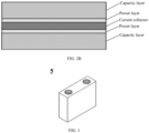
- FIG. 1A and FIG. 1B show a positive electrode plate formed according to an embodiment of this application, where a capacity layer and a power layer are formed on a surface of a current collector.
- positions of the capacity layer and the power layer can be selected according to the specific use and required performance of lithium-ion batteries.
- the capacity layer can be located under (inside) the power layer, as shown in FIG. 1A ; or the capacity layer can be located on (outside) the power layer, as shown in FIG. 1B.
- FIG. 2A and FIG. 2B show a positive electrode plate formed according to another embodiment of this application, where a capacity layer and a power layer are respectively formed on two surfaces of a current collector in the middle.
- the power layer covers the entire outer surface of the capacity layer (a surface of the capacity layer facing away from the current collector).
- the capacity layer covers the entire outer surface of the power layer (a surface of the power layer facing away from the current collector).
- the capacity layer is located under (inside) the power layer.
- the capacity layer and the power layer are in direct contact with each other, without any other layer therebetween.
- one or more additional intermediate layers are optionally disposed between the capacity layer and the power layer.
- the intermediate layer may be a conductive primer layer (which may be composed of a binder and a conductive agent, for example, the binder and conductive agent listed in the foregoing description of the capacity layer), or may contain any other auxiliary agents known in the art, or may optionally contain same or different positive electrode active materials.
- the lithium-ion battery can be used in lithium-ion batteries.
- the lithium-ion battery includes a positive electrode plate, a negative electrode plate, a separator, an electrolyte, and the like.
- active ions are intercalated and deintercalated between the positive electrode plate and the negative electrode plate.
- the electrolyte migrates ions between the positive electrode plate and the negative electrode plate.
- the lithium-ion battery of this application includes the negative electrode plate, where the negative electrode plate includes a negative electrode current collector and a negative electrode film layer provided on at least one surface of the negative electrode current collector, and the negative electrode film layer includes a negative electrode active material, a binder, a conductive agent, and another optional additive.
- examples of the negative electrode active material include one or more of the following: natural graphite, artificial graphite, soft carbon, hard carbon, silicon-based material, tin-based material, and lithium titanate.
- the silicon-based material may be selected from one or more of elemental silicon, silicon oxide, and a silicon-carbon composite.
- the tin-based material may be selected from one or more of elemental tin, tin-oxygen compounds, and tin alloys.
- the conductive agent may include one or more of superconducting carbon, carbon black (for example, acetylene black and Ketjen black), carbon dots, carbon nanotubes, graphene, and carbon nanofibers.
- the binder may include styrene-butadiene rubber (SBR), water soluble unsaturated resin SR-1B, polyacrylic acid (PAA), polymethylacrylic acid (PMAA), polyacrylic acid sodium (PAAS), polyacrylamide (PAM), polyvinyl alcohol (PVA), sodium alginate (SA), and carboxymethyl chitosan (CMCS).
- Other optional additives are, for example, thickeners (for example, carboxymethyl cellulose CMC and sodium carboxymethyl cellulose CMC-Na), PTC thermistor materials, and the like.
- the negative electrode plate can be prepared by dispersing the negative electrode active material, binder, conductive agent, other optional additives, and the like in a solvent, and stirring to form a uniform slurry with a specified solid percentage, where the solvent may be N-methylpyrrolidone (NMP) or deionized water, and based on a total weight of the prepared slurry, the solid percentage of the slurry may be 30-80 wt%, for example, 50-70 wt%, or 55-65 wt%; and applying the slurry on the negative electrode current collector, followed by drying and optionally cold pressing, to form the negative electrode plate, where the negative electrode current collector may be a metal foil or a composite current collector, for example, the metal foil may be a copper foil, a silver foil, an iron foil, or a foil made of alloys of the foregoing metal.
- NMP N-methylpyrrolidone
- the solid percentage of the slurry may be 30-80 wt%, for example, 50-70 w
- the composite current collector may include a polymer matrix and a metal layer formed on at least one surface of the polymer matrix, and may be formed by forming a metal material (such as copper, copper alloy, nickel, nickel alloy, titanium, titanium alloy, silver, and silver alloy) on the polymer matrix (for example, a matrix of polypropylene PP, polyethylene glycol terephthalate PET, polybutylene terephthalate PBT, polystyrene PS, polyethylene PE, and copolymers thereof).
- a metal material such as copper, copper alloy, nickel, nickel alloy, titanium, titanium alloy, silver, and silver alloy
- the negative electrode plate does not exclude additional functional layers other than the negative electrode active material layer.
- the negative electrode plate according to this application may further include a conductive primer layer (for example, consisting of the conductive agent and binder described above that can be used for the negative electrode active material layer) sandwiched between the negative electrode current collector and the negative electrode active material layer and disposed on the surface of the negative electrode current collector.
- the negative electrode plate according to this application may further include a protective layer covering the surface of the negative electrode active material layer.
- the electrolyte migrates ions between the positive electrode plate and the negative electrode plate.
- the electrolyte may be selected from at least one of a solid electrolyte and a liquid electrolyte (or electrolyte solution).
- the electrolyte is a liquid electrolyte.
- the electrolyte includes an electrolytic salt and a solvent.
- the electrolytic salt may be selected from one or more of LiPF 6 (lithium hexafluorophosphate), LiBF 4 (lithium tetrafluoroborate), LiClO 4 (lithium perchlorate), LiAsF 6 (lithium hexafluoroborate), LiFSI (lithium bis(fluorosulfonyl)imide), LiTFSI (lithium bis-trifluoromethanesulfonimide), LiTFS (lithium trifluoromethanesulfonat), LiDFOB (lithium difluorooxalatoborate), LiBOB (lithium bisoxalatoborate), LiPO 2 F 2 (lithium difluorophosphate), LiDFOP (lithium difluorophosphate), and LiTFOP (lithium tetrafluoro oxalate phosphate).
- LiPF 6 lithium hexafluorophosphate
- LiBF 4 lithium tetrafluoroborate
- LiClO 4 lithium
- the solvent may be selected from one or more of the following: ethylene carbonate (EC), propylene carbonate (PC), ethyl methyl carbonate (EMC), diethyl carbonate (DEC), dimethyl carbonate (DMC), dipropyl carbonate (DPC), methyl propyl carbonate (MPC), ethyl propyl carbonate (EPC), butylene carbonate (BC), fluoroethylene carbonate (FEC), methylmethyl formate (MF), methyl acetate (MA), ethyl acetate (EA), propyl acetate (PA), methyl propionate (MP), ethyl propionate (EP), propyl propionate (PP), methyl butyrate (MB), ethyl butyrate (EB), 1,4-butyrolactone (GBL), tetramethylene sulfone (SF), methyl sulfone (MSM), ethyl methyl sulfone (EMS),
- EC ethylene
- a percentage of the solvent is 60-99 wt%, for example, 65-95 wt%, 70-90 wt%, 75-89 wt%, or 80-85 wt%, or within a value range defined by any one of the upper limits and any one of the lower limits.
- a percentage of the electrolyte is 1-40 wt%, for example, 5-35 wt%, 10-30 wt%, 11-25 wt%, or 15-20 wt%, or within a value range defined by any one of the upper limits and any one of the lower limits.
- the electrolyte may further optionally include an additive.
- the additive may include one or more of the following: a negative electrode film forming additive and a positive electrode film forming additive, or may include an additive capable of improving some performance of batteries, for example, an additive for improving over-charge performance of batteries, an additive for improving high-temperature performance of batteries, or an additive for improving low-temperature performance of batteries.
- the battery further includes a separator, where the separator separates a positive electrode side of the battery from a negative electrode side, and provides selective transmission or barrier for substances of different types, sizes and charges in the system.
- the separator is an electronic insulator, which physically separates the positive electrode active material of the battery from the negative electrode active material of the battery, preventing internal short circuit and forming an electric field in a given direction, and which allows ions in the battery to migrate between the positive and negative electrodes through the separator.
- a material for preparing the separator may include one or more of glass fiber, non-woven fabric, polyethylene, polypropylene, and polyvinylidene fluoride, and may be a porous film or a non-porous film, and preferably a polyethylene-polypropylene porous film.
- the separator may be a single-layer film or a multilayer composite film. When the separator is a multilayer composite thin film, each layer may be made of the same or different materials.
- the above positive electrode plate, negative electrode plate, and separator may be made into an electrode assembly/a bare cell through winding or lamination.
- the lithium-ion battery may include an outer package, or a housing.
- the outer package may be used for packaging the electrode assembly and the electrolyte.
- the outer package of the battery may be a hard shell, for example, a hard plastic shell, an aluminum shell, or a steel shell.
- the outer package of the battery may alternatively be a soft pack, for example, a soft pouch.
- a material of the soft pack may be plastic, for example, one or more of polypropylene (PP), polybutylene terephthalate (PBT), polybutylene succinate (PBS), and the like.
- the battery according to this application may be cylindrical, rectangular, or of any other shapes.
- FIG. 3 shows a rectangular battery 5 as an example.
- FIG. 4 is an exploded view of the battery 5 in FIG. 3 .
- the outer package may include a housing 51 and a cover plate 53.
- the housing 51 may include a base plate and side plates connected to the base plate, and the base plate and the side plates enclose an accommodating cavity.
- the housing 51 has an opening communicating with the accommodating cavity, and the cover plate 53 can cover the opening to close the accommodating cavity.
- a positive electrode plate, a negative electrode plate, and a separator may be made into an electrode assembly 52 through winding or lamination.
- the electrode assembly is packaged in the accommodating cavity, and the electrolyte infiltrates the electrode assembly 52.
- the battery 5 may include one or more electrode assemblies 52.
- the battery is subjected to conventional formation, so that a solid electrolyte interface layer (SEI film) is formed on a surface of the negative electrode, thereby obtaining a battery meeting product requirements.
- SEI film solid electrolyte interface layer
- a plurality of batteries may be assembled into a battery module, the battery module includes two or more batteries, and a quantity of batteries included in the battery module depends on application of the battery module land parameters of a single battery module.
- FIG. 5 shows a battery module 4 as an example.
- a plurality of batteries 5 may be sequentially arranged in a length direction of the battery module 4.
- the batteries may alternatively be arranged in any other manners.
- the plurality of batteries 5 may be fastened through fasteners.
- the battery module 4 may further include a housing having an accommodating space, and the plurality of batteries 5 are accommodated in the accommodating space.
- two or more battery modules may be assembled into a battery pack, and a quantity of battery modules included in the battery pack depends on application of the battery pack and parameters of a single battery module.
- the battery pack may include a battery box and a plurality of battery modules disposed in the battery box, where the battery box includes an upper box body and a lower box body, the upper box body can cover and fits well with the lower box body to form an enclosed space for accommodating the battery modules.
- the two or more battery modules may be arranged in the battery box in a required manner.
- FIG. 6 and FIG. 7 show a battery pack 1 as an example.
- the battery pack 1 may include a battery box and a plurality of battery modules 4 arranged in the battery box.
- the battery box includes the upper box body 2 and the lower box body 3.
- the upper box body 2 is configured to cover the lower box body 3 to form the enclosed space for accommodating the battery modules 4.
- the plurality of battery modules 4 may be arranged in the battery box in any manner.
- the electric apparatus includes at least one of the battery, the battery module, or the battery pack according to this application.
- the battery, the battery module, or the battery pack may be used as a power source for the electric apparatus or an energy storage unit of the electric apparatus.
- the electric apparatus includes, but is not limited to, a mobile digital device (for example, a mobile phone or a notebook computer), an electric vehicle (for example, a battery electric vehicle, a hybrid electric vehicle, a plug-in hybrid electric vehicle, an electric bicycle, an electric scooter, an electric golf vehicle, or an electric truck), an electric train, a ship, a satellite, an energy storage system, and the like.
- FIG. 8 shows an apparatus as an example.
- the apparatus is a battery electric vehicle, a hybrid electric vehicle, a plug-in hybrid electric vehicle, or the like.
- a battery pack or a battery module may be used.
- the apparatus may be a mobile phone, a tablet computer, a laptop computer, or the like.
- the apparatus usually needs to be light and thin, and a battery may be used as a power source.
- Lithium iron phosphate has a particle size D50 of 0.4 ⁇ m (for power layer) or 1.2 ⁇ m (for capacity layer), and is purchased from Shanghai Maclean Biochemical Technology Co., Ltd.
- Li 5 FeO 4 and Li 2 Cu 0.5 Ni 0.5 O 2 According to literatures, Li 5 FeO 4 and Li 2 Cu 0.5 Ni 0.5 O 2 are made through a conventional solid-phase mixing and sintering process. D50 of Li 5 FeO 4 is 5 ⁇ m and D50 of Li 2 Cu 0.5 Ni 0.5 O 2 is 5 ⁇ m.
- Acetylene black A conductive agent purchased from Shanghai Maclean Biochemical Technology Co., Ltd.
- PVDF A binder polyvinylidene fluoride purchased from Shanghai Maclean Biochemical Technology Co., Ltd.
- CMC A thickener carboxymethyl cellulose, purchased from Shanghai Maclean Biochemical Technology Co., Ltd.
- NMP A solvent N-methylpyrrolidone, analytically pure Separator A polyethylene/propylene porous polymer film, with a thickness of 12 ⁇ m, is purchased from Celgard.
- the particle sizes recorded in this application are measured using a laser scattering particle size analyzer.
- Li 5 FeO 4 is used as a pre-lithiation agent to prepare lithium-ion batteries and characterize performance thereof.
- Example 1-1 the lithium-ion battery was obtained by the following steps.
- the first positive electrode active material lithium iron phosphate (with a D50 of 1.2 ⁇ m), the conductive agent acetylene black, and the binder polyvinylidene fluoride were weighed according to a solid weight ratio of 97:1:2, and these raw materials were mixed in N-methylpyrrolidone to form an uniform slurry with a solid percentage of 62 wt%.
- the slurry was applied on a 60 ⁇ m thick aluminum foil current collector, followed by drying and cold pressing, to form a capacity layer.
- the capacity layer has a coating weight of 15.6 g/cm 2 and a compacted density of 2.5 g/cm 3 .
- the second positive electrode active material lithium iron phosphate (with a D50 of 0.4 ⁇ m), the pre-lithiation agent Li 5 FeO 4 (with a D50 of 5 ⁇ m), the conductive agent acetylene black, and the binder polyvinylidene fluoride were weighed according to a solid weight ratio of 94.5:2.5:1:2, and these raw materials were mixed in N-methylpyrrolidone to form an uniform slurry with a solid percentage of 60 wt%.
- the slurry was applied on the capacity layer prepared in Step 1, followed by drying and cold pressing, to form a power layer.
- the power layer has a coating weight of 4 g/cm 2 and a compacted density of 2.3 g/cm 3 .
- the positive electrode plate including the current collector, the capacity layer, and the power layer was prepared.
- a weight ratio of lithium iron phosphate contained in the power layer and lithium iron phosphate contained in the capacity layer is 2:8.
- the negative electrode active material artificial graphite, the conductive agent acetylene black, and the binder styrene-butadiene rubber, and the thickener sodium carboxymethyl cellulose were weighed according to a solid weight ratio of 96.5:0.7:1.8:1, and these raw materials were mixed in deionized water to form an uniform slurry with a solid percentage of 56 wt%.
- the slurry was applied on a 60 ⁇ m thick copper foil current collector, followed by drying and cold pressing, to form a negative electrode plate.
- a coating weight of the coating layer on the current collector is 10.1 g/cm 2 .
- the positive electrode plate, the separator, and the negative electrode plate were stacked in sequence, to form a laminated structure.
- the laminated structure was placed in an aluminum battery housing, the electrolyte was injected into the aluminum battery housing, and the housing was packaged.
- the lithium-ion battery in Example 1 was prepared.
- five batteries were made in parallel for a parallel test of high-temperature storage performance.
- Example 1-2 the lithium-ion battery was obtained through the same steps in Example 1-1, except that in the step of preparing the power layer of the positive electrode plate, the solid weight ratio of the second positive electrode active material lithium iron phosphate, the pre-lithiation agent Li 5 FeO 4 , the conductive agent acetylene black, and the binder polyvinylidene fluoride was 96:1:1:2.
- the coating weight of the capacity layer was changed correspondingly, so that the weight ratio of lithium iron phosphate contained in the power layer and lithium iron phosphate contained in the capacity layer was kept at 2:8.
- Example 1-3 the lithium-ion battery was obtained through the same steps in Example 1-1, except that in the step of preparing the power layer of the positive electrode plate, the solid weight ratio of the second positive electrode active material lithium iron phosphate, the pre-lithiation agent Li 5 FeO 4 , the conductive agent acetylene black, and the binder polyvinylidene fluoride was 87:10:1:2.
- the coating weight of the capacity layer was changed correspondingly, so that the weight ratio of lithium iron phosphate contained in the power layer and lithium iron phosphate contained in the capacity layer was kept at 2:8.
- Example 1-4 the lithium-ion battery was obtained through the same steps in Example 1-1, except that in the step of preparing the power layer of the positive electrode plate, the solid weight ratio of the second positive electrode active material lithium iron phosphate, the pre-lithiation agent Li 5 FeO 4 , the conductive agent acetylene black, and the binder polyvinylidene fluoride was 77:20:1:2.
- the coating weight of the capacity layer was changed correspondingly, so that the weight ratio of lithium iron phosphate contained in the power layer and lithium iron phosphate contained in the capacity layer was kept at 2:8.
- Example 1-5 the lithium-ion battery was obtained through the same steps in Example 1-1, except that the coating weights of the power layer and the capacity layer were adjusted to make the weight ratio of lithium iron phosphate contained in the power layer and lithium iron phosphate contained in the capacity layer be 5:5 while keeping the total coating weight of the power layer and the capacity layer unchanged.
- Example 1-6 the lithium-ion battery was obtained through the same steps in Example 1-1, except that the coating weights of the power layer and the capacity layer were adjusted to make the weight ratio of lithium iron phosphate contained in the power layer and lithium iron phosphate contained in the capacity layer be 8:2 while keeping the total coating weight of the power layer and the capacity layer unchanged.
- Comparative Example 1-1 the lithium-ion battery was obtained through the same steps in Example 1-1, except that in the positive electrode plate, only the capacity layer, but no power layer, was formed on the current collector, and the coating weight of the capacity layer in Comparative Example 1-1 was equal to the sum of the coating weights of the capacity layer and the power layer in Example 1-1.
- Comparative Example 1-2 the lithium-ion battery was obtained through the same steps in Comparative Example 1-1, except that lithium iron phosphate with a D50 of 1.2 ⁇ m in Comparative Example 1-1 was all replaced by the same weight of lithium iron phosphate with a D50 of 0.4 ⁇ m.
- the lithium-ion battery was obtained through the same steps in Example 1-1, except that during preparation of the power layer, solid raw materials used were the second positive electrode active material lithium iron phosphate (with a D50 of 0.4 ⁇ m), the conductive agent acetylene black, and the binder polyvinylidene fluoride at a solid weight ratio of 97:1:2, without the pre-lithiation agent.
- solid raw materials used were the second positive electrode active material lithium iron phosphate (with a D50 of 0.4 ⁇ m), the conductive agent acetylene black, and the binder polyvinylidene fluoride at a solid weight ratio of 97:1:2, without the pre-lithiation agent.
- Comparative Example 1-4 the lithium-ion battery was obtained through the same steps in Example 1-1, except that during preparation of the power layer, lithium iron phosphate with a D50 of 1.2 ⁇ m was used as the second positive electrode active material. In other words, in Comparative Example 1-4, same lithium iron phosphate with a D50 of 1.2 ⁇ m was used in the capacity layer and the power layer.
- the foregoing charged battery was taken and discharged to an end-of-discharge voltage at a constant current of 0.33C, and measurement was performed to obtain a discharge capacity Ed0.
- the secondary battery under test was charged at room temperature to a voltage of 3.65 V at 1C, and then discharged to a voltage of 2.5 V at 1C, and the reversible capacity measured at that time was E0.
- Examples 2-1 to 2-6 the lithium-ion batteries were obtained by using same steps in Examples 1-1 to 1-6 respectively, except that during preparation of the power layer, the same weight of Li 2 Ni 0.5 Cu 0.5 O 2 , instead of Li 5 FeO 4 , was used as the pre-lithiation agent.
- Comparative Example 2-1 the lithium-ion battery was obtained through the same steps in Comparative Example 1-4, except that during preparation of the power layer, the same weight of Li 2 Ni 0.5 Cu 0.5 O 2 , instead of Li 5 FeO 4 , was used as the pre-lithiation agent.
Landscapes
- Chemical & Material Sciences (AREA)
- Engineering & Computer Science (AREA)
- Chemical Kinetics & Catalysis (AREA)
- Electrochemistry (AREA)
- General Chemical & Material Sciences (AREA)
- Materials Engineering (AREA)
- Manufacturing & Machinery (AREA)
- Composite Materials (AREA)
- Inorganic Chemistry (AREA)
- Battery Electrode And Active Subsutance (AREA)
Abstract
Description
- This application relates to the field of batteries, and more specifically, to a positive electrode plate for lithium-ion battery, and further relates to a battery, a battery module, a battery pack, and an electric apparatus containing the same.
- With the development of the related fields in recent years, rechargeable batteries (also known as secondary batteries) are increasingly used in fields such as consumer goods, new energy vehicles, large-scale energy storage, aerospace, ships and heavy machinery, even serving as the main power and energy supply equipment in these fields. In various available secondary batteries, lithium-ion secondary batteries have received widespread attention due to their excellent performance. However, lithium-ion secondary batteries also have some technical problems that have not been resolved so far. For example, how pre-lithiation technology for lithium-ion battery is improved is one of the great concerns. Generally, the existing pre-lithiation technology for lithium-ion battery is simply applying an additional pre-lithiation layer containing pre-lithiation agents is to the positive electrode active material layer. However, these pre-lithiation agents have strong alkalinity and large particle size, while the pre-lithiation layer is usually required to be thin. In this case, it is difficult to form a uniform pre-lithiation layer, and the non-uniformity of the pre-lithiation layer significantly increases the risk of lithium precipitation and local swelling force of the battery cell during charging and discharging, leading to undesirable service life and power of the battery and significantly increased probability of battery failure. In addition, during battery charging and discharging, electronic isolation oxide is formed after the pre-lithiation agent releases lithium, affecting conductivity of the positive electrode plate and causing performance of the lithium-ion battery to drop. In addition, it is well known in the art that the use of a positive electrode active material having a small particle size and a large BET specific surface area often leads to higher content of entrained impurities and more side reactions, significantly shortening the effective service life of lithium-ion batteries. However, the use of a positive electrode active material having a large particle size and a small BET specific surface area leads to reduced power of batteries. So far, such contradiction has not been well resolved.
- Therefore, an improved technical solution is urgently needed in the art to effectively overcome the above problems in an economical and simple manner, achieve excellent pre-lithiation effect, significantly reduce or even eliminate the impact on the performance of batteries caused by a product resulting from the pre-lithiation agents releasing lithium, significantly reduce the risk of crystallization or swelling of batteries, and improve the power efficiency and cycling performance of batteries.
- Through a lot of in-depth researches, the inventors of this application have unexpectedly designed a unique technical solution to resolve the foregoing technical problems that urgently need to be resolved in the prior art by specially designing a specific composition of multiple layers in positive electrode plates.
- A first aspect of this application provides a positive electrode plate for lithium-ion battery, where the positive electrode plate includes: i) a current collector; ii) at least one capacity layer, where the capacity layer includes a first binder, a first conductive agent, and a first positive electrode active material, the first positive electrode active material having a first median particle size; and ii) at least one power layer, where the power layer includes a second binder, a second conductive agent, a pre-lithiation agent, and a second positive electrode active material, the second positive electrode active material having a second median particle size; where the first median particle size is greater than the second median particle size. In this application, the capacity layer containing the first positive electrode active material and the power layer containing both the pre-lithiation agent and the second positive electrode active material are used, and the median particle sizes of the positive electrode active materials in the two layers are controlled, guaranteeing uniformity of the power layer in a simple and economical manner, and effectively inhibiting the adverse impact on the performance of the battery caused by an electronic isolation oxide generated after the pre-lithiation agent releases lithium. In this way, the risk of crystallization or swelling of batteries is significantly reduced, and power efficiency and cycling performance of batteries are improved.
- According to an embodiment of the first aspect of this application, the positive electrode plate includes at least one capacity layer located on at least one surface of the current collector, and at least one power layer located on a surface of the at least one capacity layer facing away from the current collector. To be specific, the capacity layer is on the bottom (inside), and the power layer is on the top (outside). According to another embodiment of the first aspect of this application, the positive electrode plate includes at least one power layer located on at least one surface of the current collector, and at least one capacity layer located on a surface of the at least one power layer facing away from the current collector. To be specific, the capacity layer is on the top (outside), and the power layer is on the bottom (inside). Any one of the foregoing design structures is selected according to the desired use and operating environment of the lithium-ion battery, allowing the lithium-ion battery to better meet the performance requirement.
- According to an embodiment of the first aspect of this application, the first median particle size of the first positive electrode active material is 0.8-1.3 µm. According to another embodiment of the first aspect of this application, the second median particle size of the second positive electrode active material is 0.1-0.7 µm, and preferably 0.2-0.45 µm. The particle sizes of the positive electrode active materials in the capacity layer and power layer being specially designed can ensure the energy density of the positive electrode plate while reducing impact on the conductivity caused by a product resulting from a pre-lithiation agent releasing lithium.
- According to another embodiment of the first aspect of this application, the first positive electrode active material and the second positive electrode active material are each independently selected from lithium cobaltate, lithium iron phosphate, lithium manganese iron phosphate, lithium vanadium phosphate, lithium vanadyl phosphate, lithium vanadate, lithium manganate, positive electrode active material shown in formula I, positive electrode active material shown in formula II, and a combination thereof:
LiNixCoyAzO2 formula I
in formula I, A is selected from one or more of the following elements: manganese, aluminum, copper, zinc, tin, titanium, magnesium, and iron, 0.01≤x≤0.98, 0.01≤y≤0.98, 0.01≤z≤0.98, and x+y+z=1;
LlFe1-m-nMnmBnPO4 formula II
in formula II, 0≤m≤1, 0≤n≤0.1, and B is selected from at least one of transition metal elements other than Fe and Mn and non-transition metal elements. According to another embodiment of the first aspect of this application, the first positive electrode active material is lithium iron phosphate, and the second positive electrode active material is also lithium iron phosphate. All the foregoing positive electrode active materials can be used in the technical solution of this application, so that manufacturing of batteries is highly flexible and appropriate positive electrode active materials can be selected according to battery performance and cost requirements. In other words, the technical solution of this application has a wide application range. - According to another embodiment of the first aspect of this application, the pre-lithiation agent is selected from one or more of the following: Li2M1O2, Li2M2O3, Li2M3O4, Li3M4O4, Li5M5O4, Li5M6O6, Li6M7O4, and LiaCbOc. According to another embodiment of the first aspect of this application, the pre-lithiation agent is Li2M1O2, where M1 is selected from one or more of the following: Cu, Ni, Mn, Fe, Cr, Mo, Zn, Sn, Mg, and Ca. According to another embodiment of the first aspect of this application, the pre-lithiation agent is Li2M2O3, where M2 is selected from one or more of the following: Ni, Co, Fe, Mn, Sn, Cr, Mo, Zr, Si, Cu, and Ru. According to another embodiment of the first aspect of this application, the pre-lithiation agent is Li2M3O4, where M3 is selected from one or more of the following: Ni, Co, Fe, Mn, Sn, Cr, V, and Nb. According to another embodiment of the first aspect of this application, the pre-lithiation agent is Li3M4O4, where M4 is selected from one or more of the following: Cu, Ni, Mn, Fe, Cr, Mo, Zn, Sn, Mg, and Ca. According to another embodiment of the first aspect of this application, the pre-lithiation agent is Li5M5O4, where M5 is selected from one or more of the following: Ni, Co, Fe, Mn, Sn, Cr, and Mo. According to another embodiment of the first aspect of this application, the pre-lithiation agent is Li5M6O6, where M6 is selected from one or more of the following: Cu, Ni, Mn, Fe, Cr, Mo, Zn, Sn, Mg, and Ca. According to another embodiment of the first aspect of this application, the pre-lithiation agent is Li6M7O4, where M7 is selected from one or more of the following: Ni, Co, Mn, Fe, and Ru. According to another embodiment of the first aspect of this application, the pre-lithiation agent is LiaCbOc, where a is an
integer integer integer - According to another embodiment of the first aspect of this application, a median particle size of the pre-lithiation agent is 5-15 µm, for example, 6-10 µm. Adjustment of the median particle size of the pre-lithiation agent facilitates formation of a uniform and thin power layer, so as to improve the power and service life of batteries and further reduce the risk of lithium precipitation and swelling of battery cells.
- According to another embodiment of the first aspect of this application, based on the total weight of the capacity layer, the capacity layer includes 1-30 wt% of the first binder, 0.1-10 wt% of the first conductive agent, and 60-98.5 wt% of the first positive electrode active material. According to another embodiment of the first aspect of this application, based on the total weight of the power layer, the power layer includes 1-30 wt% of the second binder, 0.1-10 wt% of the second conductive agent, 0.1-30 wt% of the pre-lithiation agent, and 50-97 wt% of the second positive electrode active material. According to another embodiment of the first aspect of this application, a percentage of the second conductive agent in the power layer is equal to or greater than a percentage of the first conductive agent in the capacity layer. According to another embodiment of the first aspect of this application, a weight ratio of the power layer and the capacity layer is 1:9 to 9:1. Selection of the foregoing preferred ratio further improves pre-lithiation effect. To be specific, lithium batteries have high first-cycle coulombic efficiency, optimized energy density, and excellent cycle life.
- A second aspect of this application provides a lithium-ion battery, where the lithium-ion battery includes a negative electrode plate, an electrolyte, a separator, and the positive electrode plate for lithium-ion battery according to any one of the embodiments in the first aspect. A third aspect of this application provides a battery module containing the lithium-ion battery in the second aspect of this application. A fourth aspect of this application provides a battery pack containing the battery module in the third aspect of this application. The lithium-ion battery, the battery module, and the battery pack achieve excellent pre-lithiation effect due to the use of the positive electrode plate of this application. To be specific, the undesirable battery power caused by a product resulting from a pre-lithiation material releasing lithium is well addressed, the effective service life of the battery is significantly extended, and the battery is secured with stable and excellent efficiency, conductivity, power, and energy density in the effective service life of the battery.
- A fifth aspect of this application provides an electric apparatus containing at least one of the lithium-ion battery, the battery module, or the battery pack in any one of the foregoing aspects. The electric apparatus achieves excellent pre-lithiation effect due to the use of the positive electrode plate of this application. To be specific, the undesirable battery power caused by a product resulting from a pre-lithiation material releasing lithium is well addressed, the effective service life of the battery is significantly extended, and the battery is secured with stable and excellent efficiency, conductivity, power, and energy density in the effective service life of the battery, thereby ensuring long-term stable operation of the electric apparatus.
-
-
FIG. 1A is a cross-sectional view of a positive electrode plate according to an embodiment of this application, where a capacity layer and a power layer are disposed on a surface of a current collector, and the capacity layer is disposed under the power layer.FIG. 1B is a cross-sectional view of a positive electrode plate according to another embodiment of this application, where a capacity layer and a power layer are disposed on a surface of a current collector, and the capacity layer is disposed on (outside) the power layer. -
FIG. 2A is a cross-sectional view of a positive electrode plate according to another embodiment of this application, where a capacity layer and a power layer are respectively disposed on two surfaces of a current collector, and the capacity layer is disposed under the power layer.FIG. 2B is a cross-sectional view of a positive electrode plate according to another embodiment of this application, where a capacity layer and a power layer are respectively disposed on two surfaces of a current collector, and the capacity layer is disposed on (outside) the power layer. -
FIG. 3 is a schematic diagram of an embodiment of a lithium-ion battery of this application. -
FIG. 4 is an exploded view of the lithium-ion battery inFIG. 3 . -
FIG. 5 is a schematic diagram of a battery module according to an embodiment of this application. -
FIG. 6 is a schematic diagram of a battery pack according to an embodiment of this application. -
FIG. 7 is an exploded view of the battery pack inFIG. 6 . -
FIG. 8 is a schematic diagram of an embodiment of an electric apparatus using the lithium-ion battery in this application as a power source. - The following specific embodiments describe design details of a positive electrode plate and a lithium-ion battery, battery module, battery pack, and electric apparatus containing the same designed in this application.
- "Ranges" disclosed herein are defined in the form of lower and upper limits. Given ranges are defined by selecting lower and upper limits, and the selected lower and upper limits define boundaries of special ranges. Ranges defined in this method may or may not include end values, and any combinations may be used, meaning any lower limit may be combined with any upper limit to form a range. For example, if ranges of 60-120 and 80-110 are provided for a specific parameter, it is understood that ranges of 60-110 and 80-120 can also be envisioned. In addition, if minimum values of a range are given as 1 and 2, and maximum values of the range are given as 3, 4, and 5, the following ranges can all be envisioned: 1-3, 1-4, 1-5, 2-3, 2-4, and 2-5. In this application, unless otherwise specified, a value range of "a-b" is a short representation of any combination of real numbers from a to b, where both a and b are real numbers. For example, a value range of "0-5" means that all real numbers in the range of "0-5" are listed herein, and "0-5" is just a short representation of a combination of these values. In addition, a parameter expressed as an integer greater than or equal to 2 is equivalent to disclosure that the parameter is, for example, an integer among 2, 3, 4, 5, 6, 7, 8, 9, 10, 11, 12, and the like.
- In this application, unless otherwise specified, all the embodiments and preferred embodiments mentioned herein may be combined with each other to form new technical solutions.
- In this application, unless otherwise specified, all the technical features and preferred features mentioned herein may be combined with each other to form new technical solutions.
- In this application, unless otherwise specified, "contain" and "include" mentioned herein may refer to open or closed inclusion. For example, the terms "contain" and "include" can mean that other unlisted components may also be contained or included, or only listed components may be contained or included.
- In the descriptions of this specification, it should be noted that "more than" and "less than" are inclusive of the present number and that "more" in "one or more" means two or more than two, unless otherwise specified.
- In the descriptions of this specification, unless otherwise stated, the term "or" is inclusive. For example, the phrase "A or B" means "A, B, or both A and B". More specifically, any one of the following conditions satisfies the condition "A or B": A is true (or present) and B is false (or not present); A is false (or not present) and B is true (or present); or both A and B are true (or present).
- In this application, the terms "lithium-ion battery" and "lithium-ion secondary battery" are used interchangeably and used to represent lithium-ion batteries that can be repeatedly charged and discharged. In the full text of this application, the terms "negative electrode" and "anode" are used interchangeably, meaning a same electrode in the battery. The terms "positive electrode" and "cathode" are used interchangeably, meaning a same electrode in the battery.
- According to an embodiment of this application, a positive electrode plate for lithium-ion battery is developed. The positive electrode plate includes a current collector, at least one capacity layer, and at least one power layer.
- According to an embodiment of this application, the current collector is a metal foil, a metal alloy foil, a polymer sheet with a metal coating, or a polymer sheet with a metal alloy coating, where metal in the metal foil and the metal coating is selected from copper, silver, iron, titanium, nickel, and aluminum; metal in the metal alloy foil and the metal alloy coating is selected from copper alloy, nickel alloy, titanium alloy, silver alloy, iron alloy, and aluminum alloy; and the polymer sheet is selected from polypropylene, polyethylene glycol terephthalate, polybutylene terephthalate, polystyrene, and mixtures or copolymers thereof.
- In the full text of this application, the "capacity layer" mainly contains a "high gram capacity/high energy" positive active material and serves as a layer to provide a high energy density for batteries. According to an embodiment of this application, the capacity layer includes a first binder, a first conductive agent, and a first positive electrode active material, the first positive electrode active material having a first median particle size. Preferably, based on the total weight of the capacity layer, the capacity layer includes 1-30 wt% of the binder, 0.1-10 wt% of the conductive agent, and 60-95 wt% of the first positive electrode active material. According to an embodiment of this application, the capacity layer does not contain a pre-lithiation agent intentionally added, especially the pre-lithiation agent mentioned in the following description of composition of the power layer.
- In this application, compositions of the capacity layer and the power layer, for example, a binder, a conductive agent, and a positive electrode active material, are each defined by prefixes "first" and "second" when being described. This is only to distinguish the compositions in the two layers in expression, but not to limit that the corresponding compositions in the two layers are necessarily different. The protection scope of this application covers embodiments in which same or different types of binders, conductive agents, and/or positive electrode active materials are used in the capacity layer and the power layer, respectively.
- According to an embodiment of this application, the first positive electrode active material for the capacity layer is selected from one or more of the following: lithium cobaltate, lithium iron phosphate, lithium manganese iron phosphate, lithium vanadium phosphate, lithium vanadyl phosphate, lithium vanadate, lithium manganate, positive electrode active material shown in formula I, positive electrode active material shown in formula II, and a combination thereof:
LiNixCoyAzO2 formula I
where A is selected from one or more of the following elements: manganese, aluminum, copper, zinc, tin, titanium, magnesium, and iron, 0.01≤x≤0.98, 0.01≤y≤0.98, 0.01≤z≤0.98, and x+y+z=1. For the positive electrode active material shown in formula I, a value of x may be within the range obtained by using any two of the following values as upper and lower limits respectively: 0.01, 0.015, 0.02, 0.025, 0.03, 0.035, 0.04, 0.05, 0.06, 0.07, 0.075, 0.08, 0.085, 0.09, 0.1, 0.15, 0.2, 0.25, 0.3, 1/3, 0.35, 0.4, 0.45, 0.5, 0 55, 0.6, 0.65, 2/3, 0.7, 0.75, 0.8, 0.85, 0.9, 0.95, and 0.99; a value of y may be within the range obtained by using any two of the following values as upper and lower limits respectively: 0.01, 0.015, 0.02, 0.025, 0.03, 0.035, 0.04, 0.05, 0.06, 0.07, 0.075, 0.08, 0.085, 0.09, 0.1, 0.15, 0.2, 0.25, 0.3, 1/3, 0.35, 0.4, 0.45, 0.5, 0 55, 0.6, 0.65, 2/3, 0.7, 0.75, 0.8, 0.85, 0.9, 0.95, and 0.99; and a value of z may be within the range obtained by using any two of the following values as upper and lower limits respectively: 0.01, 0.015, 0.02, 0.025, 0.03, 0.035, 0.04, 0.05, 0.06, 0.07, 0.075, 0.08, 0.085, 0.09, 0.1, 0.15, 0.2, 0.25, 0.3, 1/3, 0.35, 0.4, 0.45, 0.5, 0.55, 0.6, 0.65, 2/3, 0.7, 0.75, 0.8, 0.85, 0.9, 0.95, and 0.99, where the values of x, y, and z satisfy x + y + z = 1.
LiFe1-m-nMnmBnPO4 formula II
in formula II, 0≤m≤1, 0≤n≤0.1, and B is selected from at least one of transition metal elements other than Fe and Mn and non-transition metal elements. For example, for the positive electrode active material shown in formula II, a value of m may be within the range obtained by using any two of the following values as upper and lower limits respectively: 0.01, 0.015, 0.02, 0.025, 0.03, 0.035, 0.04, 0.05, 0.06, 0.07, 0.075, 0.08, 0.085, 0.09, 0.1, 0.15, 0.2, 0.25, 0.3, 1/3, 0.35, 0.4, 0.45, 0.5, 0 55, 0.6, 0.65, 2/3, 0.7, 0.75, 0.8, 0.85, 0.9, 0.95, and 0.99; a value of n may be within the range obtained by using any two of the following values as upper and lower limits respectively: 0.01, 0.015, 0.02, 0.025, 0.03, 0.035, 0.04, 0.05, 0.06, 0.07, 0.075, 0.08, 0.085, 0.09, and 0.1; and B may be selected from the following metal elements: Cu, Ni, Cr, Mo, Zn, Sn, Mg, Ca, Co, Zr, Si, Ru, V, Nb, and a combination thereof. - According to another independent embodiment of this application, the capacity layer includes only lithium iron phosphate (LiFePO4) as the first positive electrode active material, that is, the capacity layer does not include the first positive electrode active material other than lithium iron phosphate.
- Based on the total weight of the capacity layer, a percentage of the first positive electrode active material may be 60-98.5 wt%, for example, 70-98 wt% or 80-97 wt%. For example, a percentage of the first binder may be within the range obtained by using any two of the following values as upper and lower limits respectively: 60 wt%, 61 wt%, 62 wt%, 63 wt%, 64 wt%, 65 wt%, 66 wt%, 67 wt%, 68 wt%, 69 wt%, 70 wt%, 71 wt%, 72 wt%, 73 wt%, 74 wt%, 75 wt%, 76 wt%, 77 wt%, 78 wt%, 79 wt%, 80 wt%, 81 wt%, 82 wt%, 83 wt%, 84 wt%, 85 wt%, 86 wt%, 87 wt%, 88 wt%, 89 wt%, 90 wt%, 91 wt%, 92 wt%, 93 wt%, 94 wt%, 95 wt%, 96 wt%, 97 wt%, 98 wt%, and 98.5 wt%.
- In this application, a median particle size by volume is used to describe a particle size, and the median particle size by volume is measured using a laser scattering particle size analyzer. The particle size can be represented by D10, D50, D90, and D99. "D50=specific value" means that in the total volume set of particles under test, 50% (by volume) particles have a particle size greater than the specific value and the remaining 50% (by volume) particles have a particle size smaller than this particle size. "D10=specific value" means that in the total volume set of particles under test, 10% (by volume) particles have a particle size less than the specific value and the remaining particles have a particle size greater than the specific value. "D90=specific value" means that in the total volume set of particles under test, 90% (by volume) particles have a particle size less than the specific value and the remaining particles have a particle size greater than the specific value. "D99=specific value" means that in the total volume set of particles under test, 99% (by volume) particles have a particle size less than the specific value and the remaining particles have a particle size greater than the specific value. In this application, a median particle size by volume D50 of is used to describe a median particle size of particles. In other words, unless otherwise specified, the terms "median particle size", "median particle size by volume", and "volume-based median particle size" all indicate D50 of particles.
- According to an embodiment of this application, D10 of the first positive electrode active material is greater than 0.3 µm and less than or equal to 0.6 µm. For example, D10 may be within the range obtained by using any two of the following values as upper and lower limits respectively: 0.31 µm, 0.4 µm, 0.5 µm, and 0.6 µm. According to an embodiment of this application, D90 of the first positive electrode active material is greater than 1.2 µm and less than or equal to 4 µm. For example, D90 may be within the range obtained by using any two of the following values as upper and lower limits respectively: 1.21 µm, 1.3 µm, 1.4 µm, 1.5 µm, 1.6 µm, 1.7 µm, 1.8 µm, 1.9 µm, 2.0 µm, 2.1 µm, 2.2 µm, 2.3 µm, 2.4 µm, 2.5 µm, 2.6 µm, 2.7 µm, 2.8 µm, 2.9 µm, 3.0 µm, 3.1 µm, 3.2 µm, 3.3 µm, 3.4 µm, 3.5 µm, 3.6 µm, 3.7 µm, 3.8 µm, and 4.0 µm. According to an embodiment of this application, D99 of the first positive electrode active material is greater than 3.0 µm, for example, may be 3.1-8.0 µm. For example, D99 may be within the range obtained by using any two of the following values as upper and lower limits respectively: 3.1 µm, 3.2 µm, 3.3 µm, 3.4 µm, 3.5 µm, 3.6 µm, 3.7 µm, 3.8 µm, 4.0 µm, 4.1 µm, 4.2 µm, 4.3 µm, 4.4 µm, 4.5 µm, 4.6 µm, 4.7 µm, 4.8 µm, 4.9 µm, 5.0 µm, 5.1 µm, 5.2 µm, 5.3 µm, 5.4 µm, 5.5 µm, 5.6 µm, 5.7 µm, 5.8 µm, 5.9 µm, 6.0 µm, 6.1 µm, 6.2 µm, 6.3 µm, 6.4 µm, 6.5 µm, 6.6 µm, 6.7 µm, 6.8 µm, 6.9 µm, 7.0 µm, 7.1 µm, 7.2 µm, 7.3 µm, 7.4 µm, 7.5 µm, 7.6 µm, 7.7 µm, 7.8 µm, 7.9 µm, and 8.0 µm.
- According to another independent embodiment of this application, a median particle size by volume (also called volume-based median particle size) D50 of the first positive electrode active material is 0.8-1.3 µm. For example, the median particle size by volume D50 may be within the range obtained by using any two of the following values as upper and lower limits respectively: 0.8 µm, 0.9 µm, 1.0 µm, 1.1 µm, 1.2 µm, and 1.3 µm. Preferably, D50 of the first positive electrode active material for the capacity layer is greater than D50 of a second positive electrode active material for the power layer. More preferably, the following relationships are satisfied at the same time: D50 of the first positive electrode active material for the capacity layer is greater than D50 of the second positive electrode active material for the power layer, D10 of the first positive electrode active material is greater than D10 of the second positive electrode active material, D90 of the first positive electrode active material is greater than D90 of the second positive electrode active material, and D99 of the first positive electrode active material is greater than D99 of the second positive electrode active material.
- According to an embodiment of this application, the first binder for the capacity layer may include one or more of the following: polyvinylidene fluoride, polyvinyl alcohol, polyacrylic acid, polymethylacrylic acid, carboxymethyl cellulose (CMC), sodium carboxymethyl cellulose, amylum, hydroxypropyl cellulose, regenerated cellulose, polyvinylpyrrolidone, polytetrafluoroethylene, polyethylene, polypropylene, propylene-ethylene-ethylidene norbornene terpolymer, sulfonate-propylene-ethylene-ethylidene norbornene terpolymer, polystyrene-butadiene rubber (styrene-butadiene rubber, also referred to as SBR), fluorine-containing rubber, polytrifluorochloroethylene, water soluble unsaturated resin SR-1B, sodium alga acid, polyurethane, sodium polyacrylate, sodium polymethacrylate, acrylamide, carboxymethyl chitosan, and mixture or copolymers thereof. Based on the total weight of the capacity layer, a percentage of the first binder may be 1-30 wt%, for example, 1-10 wt% or 2-5 wt%. For example, the percentage of the first binder may be within the range obtained by using any two of the following values as upper and lower limits respectively: 1 wt%, 2 wt%, 3 wt%, 4 wt%, 5 wt%, 6 wt%, 7 wt%, 8 wt%, 9 wt%, 10 wt%, 11 wt%, 12 wt%, 13 wt%, 14 wt%, 15 wt%, 16 wt%, 17 wt%, 18 wt%, 19 wt%, 20 wt%, 21 wt%, 22 wt%, 23 wt%, 24 wt%, 25 wt%, 26 wt%, 27 wt%, 28 wt%, 29 wt%, and 30 wt%.
- According to an embodiment of this application, the first conductive agent for the capacity layer may include one or more of the following: superconducting carbon, acetylene black, carbon black, Ketjen black, carbon dots, carbon nanotubes, graphene graphite, meso-carbon microbeads, soft carbon, hard carbon, carbon fiber, graphene, Super P, furnace black, vapor grown carbon fiber (VGCF), and carbon nanofiber. Based on the total weight of the capacity layer, a percentage of the first conductive agent may be 0.1-10 wt%, for example, 0.5-5 wt% or 1-2 wt%. For example, the percentage of the first conductive agent may be within the range obtained by using any two of the following values as upper and lower limits respectively: 0.1 wt%, 0.2 wt%, 0.3 wt%, 0.4 wt%, 0.5 wt%, 0.6 wt%, 0.7 wt%, 0.8 wt%, 0.9 wt%, 1 wt%, 1.2 wt%, 1.5 wt%, 1.8 wt%, 2 wt%, 3 wt%, 4 wt%, 5 wt%, 6 wt%, 7 wt%, 8 wt%, 9 wt%, and 10 wt%. According to a most preferred embodiment, the first conductive agent contained in the capacity layer is a carbon-based conductive agent, for example, one or more of the foregoing carbon-based conductive agents. Based on the total weight of the capacity layer, the percentage of the first conductive agent is ≤1.3 wt%, for example, 1.2 wt%. Preferably, the percentage of the first conductive agent in the capacity layer is less than the percentage of the second conductive agent in the power layer.
- According to another independent embodiment of this application, a compacted density of the capacity layer is higher than a compacted density of the power layer, and a BET specific surface area of the capacity layer is less than a BET specific surface area of the power layer. According to an embodiment of this application, the capacity layer may have a compacted density of ≥2.4 g/cm3, for example, 2.4-3.0 g/cm3. For example, the compacted density may be within the range obtained by using any two of the following values as upper and lower limits respectively: 2.4 g/cm3, 2.5 g/cm3, 2.6 g/cm3, 2.7 g/cm3, 2.8 g/cm3, 2.9 g/cm3, and 3 g/cm3. According to another embodiment of this application, the BET specific surface area of the capacity layer is ≤13 m2/g or is 5-13 m2/g. For example, the BET specific surface area may be within the range obtained by using any two of the following values as upper and lower limits respectively: 5 m2/g, 6 m2/g, 7 m2/g, 8 m2/g, 9 m2/g, 10 m2/g, 11 m2/g, 12 m2/g, and 13 m2/g.
- In the full text of this application, the "power layer" mainly contains a "high-power" positive active material and serves a layer to provide a high power for batteries. The power layer according to this application contains both the second positive electrode active material and the pre-lithiation agent, and the particle size of the second positive electrode active material is specially designed so as to provide an excellent electronic conductive network for the pre-lithiation agent, thereby effectively inhibiting or significantly eliminating the impact on the overall conductivity of the positive electrode plate caused by of a product resulting from the pre-lithiation agent releasing lithium. According to an embodiment of this application, the power layer includes a second binder, a second conductive agent, a pre-lithiation agent, and a second positive electrode active material, the second positive electrode active material having a second median particle size. As described above, a second average diameter of the second positive electrode active material is significantly less than a first average diameter of the first positive electrode active material.
- According to an embodiment of this application, the second binder for the power layer may include one or more of the first binders listed above that can be used for the capacity layer. Preferably, for the purpose of simplifying a manufacturing process, a same type of binder is used in the power layer and the capacity layer. Based on the total weight of the power layer, a percentage of the second binder may be 1-30 wt%, for example, 1-10 wt% or 2-5 wt%. For example, the percentage of the second binder may be within the range obtained by using any two of the following values as upper and lower limits respectively: 1 wt%, 2 wt%, 3 wt%, 4 wt%, 5 wt%, 6 wt%, 7 wt%, 8 wt%, 9 wt%, 10 wt%, 11 wt%, 12 wt%, 13 wt%, 14 wt%, 15 wt%, 16 wt%, 17 wt%, 18 wt%, 19 wt%, 20 wt%, 21 wt%, 22 wt%, 23 wt%, 24 wt%, 25 wt%, 26 wt%, 27 wt%, 28 wt%, 29 wt%, and 30 wt%.
- According to an embodiment of this application, the second conductive agent for the power layer may include one or more of the first conductive agents listed above that can be used for the capacity layer. Preferably, for the purpose of simplifying a manufacturing process, a same type of conductive agent is used in the power layer and the capacity layer. Based on the total weight of the power layer, a percentage of the second conductive agent may be 0.1-10 wt%, for example, 0.5-5 wt% or 1-2 wt%. For example, the percentage of the second conductive agent may be within the range obtained by using any two of the following values as upper and lower limits respectively: 0.1 wt%, 0.2 wt%, 0.3 wt%, 0.4 wt%, 0.5 wt%, 0.6 wt%, 0.7 wt%, 0.8 wt%, 0.9 wt%, 1 wt%, 1.2 wt%, 1.5 wt%, 1.8 wt%, 2 wt%, 3 wt%, 4 wt%, 5 wt%, 6 wt%, 7 wt%, 8 wt%, 9 wt%, and 10 wt%. According to a most preferred embodiment, the second conductive agent contained in the power layer is a carbon-based conductive agent, for example, one or more of the foregoing carbon-based conductive agents. Preferably, based on the total weight of the power layer, the percentage of the second conductive agent is ≥1.4 wt%, for example, 1.45 wt%.
- According to an embodiment of this application, the second positive electrode active material for the power layer may include one or more of the first positive electrode active materials listed above that can be used for the capacity layer. Preferably, for the purpose of simplifying a manufacturing process, a same type of positive electrode active material is used in the power layer and the capacity layer. More preferably, lithium iron phosphate is used in both the power layer and the capacity layer as the positive electrode active material.
- According to an embodiment of this application, based on the total weight of the power layer, a percentage of the second positive electrode active material may be 50-97 wt%, for example, 70-94 wt% or 80-90 wt%. For example, a percentage of the second binder may be within the range obtained by using any two of the following values as upper and lower limits respectively: 60 wt%, 61 wt%, 62 wt%, 63 wt%, 64 wt%, 65 wt%, 66 wt%, 67 wt%, 68 wt%, 69 wt%, 70 wt%, 71 wt%, 72 wt%, 73 wt%, 74 wt%, 75 wt%, 76 wt%, 77 wt%, 78 wt%, 79 wt%, 80 wt%, 81 wt%, 82 wt%, 83 wt%, 84 wt%, 85 wt%, 86 wt%, 87 wt%, 88 wt%, 89 wt%, 90 wt%, 91 wt%, 92 wt%, 93 wt%, 94 wt%, 95 wt%, 96 wt%, and 97 wt%.
- According to an embodiment of this application, D10 of the second positive electrode active material is ≤0.3 µm, for example <0.3 µm, or 0.1-0.25 µm. For example, D10 may be within the range obtained by using any two of the following values as upper and lower limits respectively: 0.1 µm, 0.15 µm, 0.20 µm, 0.25 µm, 0.28 µm, 0.29 µm, and 0.30 µm; and D10 of the second positive electrode active material is less than D10 of the first positive electrode active material. According to an embodiment of this application, D90 of the second positive electrode active material is ≤1.2 µm, for example <1.2 µm, or 0.5-1.1 µm. For example, D90 may be within the range obtained by using any two of the following values as upper and lower limits respectively: 0.5 µm, 0.6 µm, 0.7 µm, 0.8 µm, 0.9 µm, 1.0 µm, 1.1 µm, 1.15 µm, and 1.20 µm; and D90 of the second positive electrode active material is less than D90 of the first positive electrode active material. According to an embodiment of this application, D99 of the second positive electrode active material is ≤3.0 µm, for example, may be 1.0-3.0 µm. For example, D99 may be within the range obtained by using any two of the following values as upper and lower limits respectively: 1.1 µm, 1.2 µm, 1.3 µm, 1.4 µm, 1.5 µm, 1.6 µm, 1.7 µm, 1.8 µm, 1.9 µm, 2.0 µm, 2.1 µm, 2.2 µm, 2.3 µm, 2.4 µm, 2.5 µm, 2.6 µm, 2.7 µm, 2.8 µm, 2.9 µm, and 3.0 µm; and D99 of the second positive electrode active material is less than D99 of the first positive electrode active material. According to another independent embodiment of this application, a median particle size by volume (also called volume-based median particle size) D50 of the second positive electrode active material is ≤0.45 µm, or is 0.2-0.45 µm. For example, D50 may be within the range obtained by using any two of the following values as upper and lower limits respectively: 0.20 µm, 0.21 µm, 0.22 µm, 0.23 µm, 0.24 µm, 0.25 µm, 0.26 µm, 0.27 µm, 0.28 µm, 0.29 µm, 0.30 µm, 0.31 µm, 0.32 µm, 0.33 µm, 0.34 µm, 0.35 µm, 0.36 µm, 0.37 µm, 0.38 µm, 0.39 µm, 0.40 µm, 0.41 µm, 0.42 µm, 0.43 µm, 0.44 µm, and 0.45 µm; and D50 of the second positive electrode active material is less than D50 of the first positive electrode active material.
- According to an embodiment of this application, the pre-lithiation agent for the capacity layer is selected from one or more of the following: Li2M1O2, where M1 is selected from one or more of the following: Cu, Ni, Mn, Fe, Cr, Mo, Zn, Sn, Mg, and Ca; Li2M2O3, where M2 is selected from one or more of the following: Ni, Co, Fe, Mn, Sn, Cr, Mo, Zr, Si, Cu, and Ru; Li2M3O4, where M3 is selected from one or more of the following: Ni, Co, Fe, Mn, Sn, Cr, V, and Nb; Li3M4O4, where M4 is selected from one or more of the following: Cu, Ni, Mn, Fe, Cr, Mo, Zn, Sn, Mg, and Ca; Li5M5O4, where M5 is selected from one or more of the following: Ni, Co, Fe, Mn, Sn, Cr, Mo, and Al; Li5M6O6, where M6 is selected from one or more of the following: Cu, Ni, Mn, Fe, Cr, Mo, Zn, Sn, Mg, and Ca; Li6M7O4, where M5 is selected from one or more of the following: Ni, Co, Mn, Fe, and Ru; and LiaCbOc, where a is an integer 1 or 2, b is an integer 0, 1, 2, 3, or 4, and c is an integer 1, 2, 3, 4, 5, or 6.
- According to an embodiment of this application, the pre-lithiation agent is selected from one or more of the following: Li2NiO2, Li2Cu0.5Ni0.5O2, Li2MoO3, Li5FeO4, Li5Fe0.9Al0.1O4, Li6MnO4, Li6Mn0.5Ru0.5O4, Li2O, Li2O2, Li2C2O4, Li2C4O4, LiC2O2, Li2C3O5, and Li2C4O6. According to a preferred embodiment of this application, the pre-lithiation agent includes Li2Cu0.5Ni0.5O2, Li5FeO4, and a combination thereof.
- According to an embodiment of this application, a median particle size by volume D50 of the pre-lithiation agent is 5-15 µm, and preferably 6-10 µm. For example, D50 may be within the range obtained by using any two of the following values as upper and lower limits respectively: 5 µm, 6 µm, 7 µm, 8 µm, 9 µm, 10 µm, 11 µm, 12 µm, 13 µm, 14 µm, and 15 µm. According to an embodiment of this application, based on the total weight of the power layer, a percentage of the pre-lithiation agent may be 0.1-30 wt%, for example, 0.5-20 wt% or 1-10 wt%. For example, the percentage of the pre-lithiation agent can be within the range obtained by using any two of the following values as upper and lower limits respectively: 0.1 wt%, 0.2 wt%, 0.5 wt%, 0.8 wt%, 1.0 wt%, 1.2 wt%, 1.5 wt%, 1.8 wt%, 2.0 wt%, 2.2 wt%, 2.5 wt%, 2.8 wt%, 3.0 wt%, 3.2 wt%, 3.5 wt%, 3.8 wt%, 4.0 wt%, 4.2 wt%, 4.5 wt%, 4.8 wt%, 5.0 wt%, 5.2 wt%, 5.5 wt%, 5.8 wt%, 6.0 wt%, 6.2 wt%, 6.5 wt%, 6.8 wt%, 7.0 wt%, 7.2 wt%, 7.5 wt%, 7.8 wt%, 8.0 wt%, 8.2 wt%, 8.5 wt%, 8.8 wt%, 9.0 wt%, 9.2 wt%, 9.5 wt%, 9.8 wt%, 10.0 wt%, 11 wt%, 12 wt%, 13 wt%, 14 wt%, 15 wt%, 16 wt%, 17 wt%, 18 wt%, 19 wt%, 20 wt%, 21 wt%, 22 wt%, 23 wt%, 24 wt%, 25 wt%, 26 wt%, 27 wt%, 28 wt%, 29 wt%, and 30%.
- According to another independent embodiment of this application, a compacted density of the power layer is less than a compacted density of the capacity layer, and a BET specific surface area of the power layer is greater than a BET specific surface area of the capacity layer. According to an embodiment of this application, the capacity layer may have a compacted density of ≤2.3 g/cm3, for example, 1.8-2.3 g/cm3. For example, the compacted density may be within the range obtained by using any two of the following values as upper and lower limits respectively: 1.8 g/cm3, 1.9 g/cm3, 2.0 g/cm3, 2.1 g/cm3, 2.2 g/cm3, and 2.3 g/cm3. According to another embodiment of this application, the BET specific surface area of the capacity layer is ≥14 m2/g or is 14-25 m2/g. For example, the BET specific surface area may be within the range obtained by using any two of the following values as upper and lower limits respectively: 14 m2/g, 15 m2/g, 16 m2/g, 17 m2/g, 18 m2/g, 19 m2/g, 20 m2/g, 21 m2/g, 22 m2/g, 23 m2/g, 24 m2/g, and 25 m2/g.
- According to an embodiment of this application, a total coating weight of the power layer and the capacity layer (a sum of coating weights of the power layer and the capacity layer per unit area) may be 5-26 g/cm2, for example, 5 g/cm2, 6 g/cm2, 7 g/cm2, 8 g/cm2, 9 g/cm2, 10 g/cm2, 11 g/cm2, 12 g/cm2, 13 g/cm2, 14 g/cm2, 15 g/cm2, 16 g/cm2, 17 g/cm2, 18 g/cm2, 19 g/cm2, 20 g/cm2, 21 g/cm2, 22 g/cm2, 23 g/cm2, 24 g/cm2, 25 g/cm2, or 26 g/cm2. According to another embodiment of this application, a solid weight ratio of the power layer and the high-capacity layer is 1:9 to 9:1, preferably 2:8 (namely, 1:4) to 1:1, and more preferably 2:8 (namely, 1:4) to 1:2. For example, the solid weight ratio of the power layer and the high-capacity layer may be within the range obtained by using any two of the following values as upper and lower limits respectively: 1:9, 1:8, 1:7, 1:6, 1:5, 1:4, 1:3, 1:2, 1:1, 2:1, 3:1, 4:1, 5:1, 6:1, 7:1, 8:1, and 9:1.
- In the embodiments of this application, the capacity layer and the power layer on the current collector may be prepared by mixing respective components of each layer and other optional additives with a solvent or dispersant, for example, N-methylpyrrolidone (NMP) or deionized water, to form a slurry, and applying the slurry in sequence, followed by drying and cold pressing, to form a positive electrode plate including the current collector, the capacity layer, and the power layer. For example, other additives optionally contained in the capacity layer and the power layer are a thickener, a PTC thermistor material, and the like. The slurry can be applied using a conventional coating technique, for example, curtain coating, blade coating, tape casting coating, or gravure roll coating.
-
FIG. 1A and FIG. 1B show a positive electrode plate formed according to an embodiment of this application, where a capacity layer and a power layer are formed on a surface of a current collector. In this application, positions of the capacity layer and the power layer can be selected according to the specific use and required performance of lithium-ion batteries. For example, the capacity layer can be located under (inside) the power layer, as shown inFIG. 1A ; or the capacity layer can be located on (outside) the power layer, as shown inFIG. 1B. FIG. 2A andFIG. 2B show a positive electrode plate formed according to another embodiment of this application, where a capacity layer and a power layer are respectively formed on two surfaces of a current collector in the middle. It should be noted in particular that dimensions (for example, thickness) of the current collector, the capacity layer, and the power layer in the embodiments shown inFIG. 1A, FIG. 1B, FIG. 2A , andFIG. 2B are not drawn to scale, but only for clearly showing a structure of the positive electrode plate. According to an embodiment of this application, in the cases shown inFIG. 1A and FIG. 2A , the power layer covers the entire outer surface of the capacity layer (a surface of the capacity layer facing away from the current collector). According to another embodiment of this application, in the cases shown inFIG. 1B andFIG. 2B , the capacity layer covers the entire outer surface of the power layer (a surface of the power layer facing away from the current collector). According to a preferred embodiment of this application, the capacity layer is located under (inside) the power layer. - According to an embodiment of this application, the capacity layer and the power layer are in direct contact with each other, without any other layer therebetween. According to another embodiment of this application, one or more additional intermediate layers are optionally disposed between the capacity layer and the power layer. For example, the intermediate layer may be a conductive primer layer (which may be composed of a binder and a conductive agent, for example, the binder and conductive agent listed in the foregoing description of the capacity layer), or may contain any other auxiliary agents known in the art, or may optionally contain same or different positive electrode active materials.
- The positive electrode plate described in the foregoing embodiments of this application can be used in lithium-ion batteries. In an embodiment of this application, the lithium-ion battery includes a positive electrode plate, a negative electrode plate, a separator, an electrolyte, and the like. During battery charging and discharging, active ions are intercalated and deintercalated between the positive electrode plate and the negative electrode plate. The electrolyte migrates ions between the positive electrode plate and the negative electrode plate.
- The lithium-ion battery of this application includes the negative electrode plate, where the negative electrode plate includes a negative electrode current collector and a negative electrode film layer provided on at least one surface of the negative electrode current collector, and the negative electrode film layer includes a negative electrode active material, a binder, a conductive agent, and another optional additive. In an embodiment of this application, examples of the negative electrode active material include one or more of the following: natural graphite, artificial graphite, soft carbon, hard carbon, silicon-based material, tin-based material, and lithium titanate. The silicon-based material may be selected from one or more of elemental silicon, silicon oxide, and a silicon-carbon composite. The tin-based material may be selected from one or more of elemental tin, tin-oxygen compounds, and tin alloys. In an example, the conductive agent may include one or more of superconducting carbon, carbon black (for example, acetylene black and Ketjen black), carbon dots, carbon nanotubes, graphene, and carbon nanofibers. The binder may include styrene-butadiene rubber (SBR), water soluble unsaturated resin SR-1B, polyacrylic acid (PAA), polymethylacrylic acid (PMAA), polyacrylic acid sodium (PAAS), polyacrylamide (PAM), polyvinyl alcohol (PVA), sodium alginate (SA), and carboxymethyl chitosan (CMCS). Other optional additives are, for example, thickeners (for example, carboxymethyl cellulose CMC and sodium carboxymethyl cellulose CMC-Na), PTC thermistor materials, and the like.
- According to an embodiment of this application, the negative electrode plate can be prepared by dispersing the negative electrode active material, binder, conductive agent, other optional additives, and the like in a solvent, and stirring to form a uniform slurry with a specified solid percentage, where the solvent may be N-methylpyrrolidone (NMP) or deionized water, and based on a total weight of the prepared slurry, the solid percentage of the slurry may be 30-80 wt%, for example, 50-70 wt%, or 55-65 wt%; and applying the slurry on the negative electrode current collector, followed by drying and optionally cold pressing, to form the negative electrode plate, where the negative electrode current collector may be a metal foil or a composite current collector, for example, the metal foil may be a copper foil, a silver foil, an iron foil, or a foil made of alloys of the foregoing metal. The composite current collector may include a polymer matrix and a metal layer formed on at least one surface of the polymer matrix, and may be formed by forming a metal material (such as copper, copper alloy, nickel, nickel alloy, titanium, titanium alloy, silver, and silver alloy) on the polymer matrix (for example, a matrix of polypropylene PP, polyethylene glycol terephthalate PET, polybutylene terephthalate PBT, polystyrene PS, polyethylene PE, and copolymers thereof).
- In addition, in the battery of this application, the negative electrode plate does not exclude additional functional layers other than the negative electrode active material layer. For example, in some embodiments, the negative electrode plate according to this application may further include a conductive primer layer (for example, consisting of the conductive agent and binder described above that can be used for the negative electrode active material layer) sandwiched between the negative electrode current collector and the negative electrode active material layer and disposed on the surface of the negative electrode current collector. In some other embodiments, the negative electrode plate according to this application may further include a protective layer covering the surface of the negative electrode active material layer.
- The electrolyte migrates ions between the positive electrode plate and the negative electrode plate. The electrolyte may be selected from at least one of a solid electrolyte and a liquid electrolyte (or electrolyte solution). In some embodiments, the electrolyte is a liquid electrolyte. The electrolyte includes an electrolytic salt and a solvent. In some embodiments, the electrolytic salt may be selected from one or more of LiPF6 (lithium hexafluorophosphate), LiBF4 (lithium tetrafluoroborate), LiClO4 (lithium perchlorate), LiAsF6 (lithium hexafluoroborate), LiFSI (lithium bis(fluorosulfonyl)imide), LiTFSI (lithium bis-trifluoromethanesulfonimide), LiTFS (lithium trifluoromethanesulfonat), LiDFOB (lithium difluorooxalatoborate), LiBOB (lithium bisoxalatoborate), LiPO2F2 (lithium difluorophosphate), LiDFOP (lithium difluorophosphate), and LiTFOP (lithium tetrafluoro oxalate phosphate). In an embodiment of this application, the solvent may be selected from one or more of the following: ethylene carbonate (EC), propylene carbonate (PC), ethyl methyl carbonate (EMC), diethyl carbonate (DEC), dimethyl carbonate (DMC), dipropyl carbonate (DPC), methyl propyl carbonate (MPC), ethyl propyl carbonate (EPC), butylene carbonate (BC), fluoroethylene carbonate (FEC), methylmethyl formate (MF), methyl acetate (MA), ethyl acetate (EA), propyl acetate (PA), methyl propionate (MP), ethyl propionate (EP), propyl propionate (PP), methyl butyrate (MB), ethyl butyrate (EB), 1,4-butyrolactone (GBL), tetramethylene sulfone (SF), methyl sulfone (MSM), ethyl methyl sulfone (EMS), and diethyl sulfone (ESE), and preferably a mixture of two or more of the foregoing solvents, for example, a mixture of ethylene carbonate (EC) and diethyl carbonate (DEC), and more preferably a mixture of ethylene carbonate (EC) and diethyl carbonate (DEC) at a volume ratio of 1:1. In an embodiment of this application, based on the total weight of the electrolyte, a percentage of the solvent is 60-99 wt%, for example, 65-95 wt%, 70-90 wt%, 75-89 wt%, or 80-85 wt%, or within a value range defined by any one of the upper limits and any one of the lower limits. In an embodiment of this application, based on the total weight of the liquid electrolyte, a percentage of the electrolyte is 1-40 wt%, for example, 5-35 wt%, 10-30 wt%, 11-25 wt%, or 15-20 wt%, or within a value range defined by any one of the upper limits and any one of the lower limits.
- In an embodiment of this application, the electrolyte may further optionally include an additive. For example, the additive may include one or more of the following: a negative electrode film forming additive and a positive electrode film forming additive, or may include an additive capable of improving some performance of batteries, for example, an additive for improving over-charge performance of batteries, an additive for improving high-temperature performance of batteries, or an additive for improving low-temperature performance of batteries.
- In an embodiment of this application, the battery further includes a separator, where the separator separates a positive electrode side of the battery from a negative electrode side, and provides selective transmission or barrier for substances of different types, sizes and charges in the system. For example, the separator is an electronic insulator, which physically separates the positive electrode active material of the battery from the negative electrode active material of the battery, preventing internal short circuit and forming an electric field in a given direction, and which allows ions in the battery to migrate between the positive and negative electrodes through the separator. In an embodiment of this application, a material for preparing the separator may include one or more of glass fiber, non-woven fabric, polyethylene, polypropylene, and polyvinylidene fluoride, and may be a porous film or a non-porous film, and preferably a polyethylene-polypropylene porous film. The separator may be a single-layer film or a multilayer composite film. When the separator is a multilayer composite thin film, each layer may be made of the same or different materials.
- In an embodiment of this application, the above positive electrode plate, negative electrode plate, and separator may be made into an electrode assembly/a bare cell through winding or lamination.
- In an embodiment of this application, the lithium-ion battery may include an outer package, or a housing. The outer package may be used for packaging the electrode assembly and the electrolyte. In some embodiments, the outer package of the battery may be a hard shell, for example, a hard plastic shell, an aluminum shell, or a steel shell. In some other examples, the outer package of the battery may alternatively be a soft pack, for example, a soft pouch. A material of the soft pack may be plastic, for example, one or more of polypropylene (PP), polybutylene terephthalate (PBT), polybutylene succinate (PBS), and the like.
- The battery according to this application may be cylindrical, rectangular, or of any other shapes.
FIG. 3 shows arectangular battery 5 as an example.FIG. 4 is an exploded view of thebattery 5 inFIG. 3 . The outer package may include ahousing 51 and acover plate 53. Thehousing 51 may include a base plate and side plates connected to the base plate, and the base plate and the side plates enclose an accommodating cavity. Thehousing 51 has an opening communicating with the accommodating cavity, and thecover plate 53 can cover the opening to close the accommodating cavity. A positive electrode plate, a negative electrode plate, and a separator may be made into anelectrode assembly 52 through winding or lamination. The electrode assembly is packaged in the accommodating cavity, and the electrolyte infiltrates theelectrode assembly 52. Thebattery 5 may include one ormore electrode assemblies 52. - According to an embodiment of this application, after the battery is assembled and the electrolyte is injected into the battery, the battery is subjected to conventional formation, so that a solid electrolyte interface layer (SEI film) is formed on a surface of the negative electrode, thereby obtaining a battery meeting product requirements.
- In an embodiment of this application, a plurality of batteries may be assembled into a battery module, the battery module includes two or more batteries, and a quantity of batteries included in the battery module depends on application of the battery module land parameters of a single battery module.
-
FIG. 5 shows abattery module 4 as an example. Referring toFIG. 5 , in thebattery module 4, a plurality ofbatteries 5 may be sequentially arranged in a length direction of thebattery module 4. Certainly, the batteries may alternatively be arranged in any other manners. Further, the plurality ofbatteries 5 may be fastened through fasteners. Optionally, thebattery module 4 may further include a housing having an accommodating space, and the plurality ofbatteries 5 are accommodated in the accommodating space. - In an embodiment of this application, two or more battery modules may be assembled into a battery pack, and a quantity of battery modules included in the battery pack depends on application of the battery pack and parameters of a single battery module. The battery pack may include a battery box and a plurality of battery modules disposed in the battery box, where the battery box includes an upper box body and a lower box body, the upper box body can cover and fits well with the lower box body to form an enclosed space for accommodating the battery modules. The two or more battery modules may be arranged in the battery box in a required manner.
-
FIG. 6 and FIG. 7 show abattery pack 1 as an example. Referring toFIG. 6 and FIG. 7 , thebattery pack 1 may include a battery box and a plurality ofbattery modules 4 arranged in the battery box. The battery box includes theupper box body 2 and thelower box body 3. Theupper box body 2 is configured to cover thelower box body 3 to form the enclosed space for accommodating thebattery modules 4. The plurality ofbattery modules 4 may be arranged in the battery box in any manner. - In an embodiment of this application, the electric apparatus according to this application includes at least one of the battery, the battery module, or the battery pack according to this application. The battery, the battery module, or the battery pack may be used as a power source for the electric apparatus or an energy storage unit of the electric apparatus. The electric apparatus includes, but is not limited to, a mobile digital device (for example, a mobile phone or a notebook computer), an electric vehicle (for example, a battery electric vehicle, a hybrid electric vehicle, a plug-in hybrid electric vehicle, an electric bicycle, an electric scooter, an electric golf vehicle, or an electric truck), an electric train, a ship, a satellite, an energy storage system, and the like.
-
FIG. 8 shows an apparatus as an example. The apparatus is a battery electric vehicle, a hybrid electric vehicle, a plug-in hybrid electric vehicle, or the like. To meet a requirement of the apparatus for high power and high energy density, a battery pack or a battery module may be used. - In another example, the apparatus may be a mobile phone, a tablet computer, a laptop computer, or the like. The apparatus usually needs to be light and thin, and a battery may be used as a power source.
- How the positive electrode plate prepared according to the embodiments of this application influences performance of electric apparatuses is characterized hereinafter based on specific examples. However, it should be noted in particular that the scope of protection of this application is defined by the claims without being limited to the above embodiments.
- Various raw materials described in Table 1 below are used in the examples. Unless otherwise specified, the raw materials used in the examples of this application are all commercially available products.
Raw material Parameter description Lithium iron phosphate Lithium iron phosphate has a particle size D50 of 0.4 µm (for power layer) or 1.2 µm (for capacity layer), and is purchased from Shanghai Maclean Biochemical Technology Co., Ltd. Li5FeO4 and Li2Cu0.5Ni0.5O2 According to literatures, Li5FeO4 and Li2Cu0.5Ni0.5O2 are made through a conventional solid-phase mixing and sintering process. D50 of Li5FeO4 is 5 µm and D50 of Li2Cu0.5Ni0.5O2 is 5 µm. Acetylene black A conductive agent, purchased from Shanghai Maclean Biochemical Technology Co., Ltd. PVDF A binder polyvinylidene fluoride, purchased from Shanghai Maclean Biochemical Technology Co., Ltd. CMC A thickener carboxymethyl cellulose, purchased from Shanghai Maclean Biochemical Technology Co., Ltd. NMP A solvent N-methylpyrrolidone, analytically pure Separator A polyethylene/propylene porous polymer film, with a thickness of 12 µm, is purchased from Celgard. - The particle sizes recorded in this application are measured using a laser scattering particle size analyzer.
- In the following Examples 1-1 to 1-6 and Comparative Examples 1-1 to 1-4, Li5FeO4 is used as a pre-lithiation agent to prepare lithium-ion batteries and characterize performance thereof.
- In Example 1-1, the lithium-ion battery was obtained by the following steps.
- In this step, the first positive electrode active material lithium iron phosphate (with a D50 of 1.2 µm), the conductive agent acetylene black, and the binder polyvinylidene fluoride were weighed according to a solid weight ratio of 97:1:2, and these raw materials were mixed in N-methylpyrrolidone to form an uniform slurry with a solid percentage of 62 wt%. In a coating cavity, the slurry was applied on a 60 µm thick aluminum foil current collector, followed by drying and cold pressing, to form a capacity layer. The capacity layer has a coating weight of 15.6 g/cm2 and a compacted density of 2.5 g/cm3.
- In this step, the second positive electrode active material lithium iron phosphate (with a D50 of 0.4 µm), the pre-lithiation agent Li5FeO4 (with a D50 of 5 µm), the conductive agent acetylene black, and the binder polyvinylidene fluoride were weighed according to a solid weight ratio of 94.5:2.5:1:2, and these raw materials were mixed in N-methylpyrrolidone to form an uniform slurry with a solid percentage of 60 wt%. In a coating cavity, the slurry was applied on the capacity layer prepared in
Step 1, followed by drying and cold pressing, to form a power layer. The power layer has a coating weight of 4 g/cm2 and a compacted density of 2.3 g/cm3. Thus, the positive electrode plate including the current collector, the capacity layer, and the power layer was prepared. A weight ratio of lithium iron phosphate contained in the power layer and lithium iron phosphate contained in the capacity layer is 2:8. - In this step, the negative electrode active material artificial graphite, the conductive agent acetylene black, and the binder styrene-butadiene rubber, and the thickener sodium carboxymethyl cellulose were weighed according to a solid weight ratio of 96.5:0.7:1.8:1, and these raw materials were mixed in deionized water to form an uniform slurry with a solid percentage of 56 wt%. In a coating cavity, the slurry was applied on a 60 µm thick copper foil current collector, followed by drying and cold pressing, to form a negative electrode plate. A coating weight of the coating layer on the current collector is 10.1 g/cm2.
- In this step, the positive electrode plate, the separator, and the negative electrode plate were stacked in sequence, to form a laminated structure. The laminated structure was placed in an aluminum battery housing, the electrolyte was injected into the aluminum battery housing, and the housing was packaged. The electrolyte was a lithium hexafluorophosphate electrolyte solution with a concentration of 1.1 M in an EC:DEC=1:1(V:V) solvent mixture. The lithium-ion battery in Example 1 was prepared. In this example and each of the following examples and comparative examples, five batteries were made in parallel for a parallel test of high-temperature storage performance.
- In Example 1-2, the lithium-ion battery was obtained through the same steps in Example 1-1, except that in the step of preparing the power layer of the positive electrode plate, the solid weight ratio of the second positive electrode active material lithium iron phosphate, the pre-lithiation agent Li5FeO4, the conductive agent acetylene black, and the binder polyvinylidene fluoride was 96:1:1:2. In addition, the coating weight of the capacity layer was changed correspondingly, so that the weight ratio of lithium iron phosphate contained in the power layer and lithium iron phosphate contained in the capacity layer was kept at 2:8.
- In Example 1-3, the lithium-ion battery was obtained through the same steps in Example 1-1, except that in the step of preparing the power layer of the positive electrode plate, the solid weight ratio of the second positive electrode active material lithium iron phosphate, the pre-lithiation agent Li5FeO4, the conductive agent acetylene black, and the binder polyvinylidene fluoride was 87:10:1:2. In addition, the coating weight of the capacity layer was changed correspondingly, so that the weight ratio of lithium iron phosphate contained in the power layer and lithium iron phosphate contained in the capacity layer was kept at 2:8.
- In Example 1-4, the lithium-ion battery was obtained through the same steps in Example 1-1, except that in the step of preparing the power layer of the positive electrode plate, the solid weight ratio of the second positive electrode active material lithium iron phosphate, the pre-lithiation agent Li5FeO4, the conductive agent acetylene black, and the binder polyvinylidene fluoride was 77:20:1:2. In addition, the coating weight of the capacity layer was changed correspondingly, so that the weight ratio of lithium iron phosphate contained in the power layer and lithium iron phosphate contained in the capacity layer was kept at 2:8.
- In Example 1-5, the lithium-ion battery was obtained through the same steps in Example 1-1, except that the coating weights of the power layer and the capacity layer were adjusted to make the weight ratio of lithium iron phosphate contained in the power layer and lithium iron phosphate contained in the capacity layer be 5:5 while keeping the total coating weight of the power layer and the capacity layer unchanged.
- In Example 1-6, the lithium-ion battery was obtained through the same steps in Example 1-1, except that the coating weights of the power layer and the capacity layer were adjusted to make the weight ratio of lithium iron phosphate contained in the power layer and lithium iron phosphate contained in the capacity layer be 8:2 while keeping the total coating weight of the power layer and the capacity layer unchanged.
- In Comparative Example 1-1, the lithium-ion battery was obtained through the same steps in Example 1-1, except that in the positive electrode plate, only the capacity layer, but no power layer, was formed on the current collector, and the coating weight of the capacity layer in Comparative Example 1-1 was equal to the sum of the coating weights of the capacity layer and the power layer in Example 1-1.
- In Comparative Example 1-2, the lithium-ion battery was obtained through the same steps in Comparative Example 1-1, except that lithium iron phosphate with a D50 of 1.2 µm in Comparative Example 1-1 was all replaced by the same weight of lithium iron phosphate with a D50 of 0.4 µm.
- In Comparative Example 1-3, the lithium-ion battery was obtained through the same steps in Example 1-1, except that during preparation of the power layer, solid raw materials used were the second positive electrode active material lithium iron phosphate (with a D50 of 0.4 µm), the conductive agent acetylene black, and the binder polyvinylidene fluoride at a solid weight ratio of 97:1:2, without the pre-lithiation agent.
- In Comparative Example 1-4, the lithium-ion battery was obtained through the same steps in Example 1-1, except that during preparation of the power layer, lithium iron phosphate with a D50 of 1.2 µm was used as the second positive electrode active material. In other words, in Comparative Example 1-4, same lithium iron phosphate with a D50 of 1.2 µm was used in the capacity layer and the power layer.
- The following techniques were used to test the performance of the batteries prepared in Examples 1-1 to 1-6 and Comparative Examples 1-1 to 1-4.
- At room temperature (25°C), the battery was charged to an end-of-charge voltage at a constant current of 0.33C, and charged to 0.05C at a constant voltage. Measurement was performed to obtain a charging capacity Ec0, and a specific charge capacity was obtained by dividing Ec0 by a mass of the positive electrode active material of the battery. In other words, specific charge capacity (mAh/g) = first-cycle charge capacity/mass of positive electrode active material.
- The foregoing charged battery was taken and discharged to an end-of-discharge voltage at a constant current of 0.33C, and measurement was performed to obtain a discharge capacity Ed0. The specific discharge capacity was obtained by dividing Ed0 by the mass of the positive electrode active material of the battery. In other words, specific discharge capacity (mAh/g) = first-cycle discharge capacity/mass of positive electrode active material.
- The specific charge capacity test and the specific discharge capacity test were repeated five times each; and the average values of test results were the specific charge capacity and the specific discharge capacity in Table 1.
- Parameters of internal dimensions of the battery, length a, width b, and height c, were measured. Each battery was charged at room temperature to a voltage of 3.65 V at 1C, and then discharged to a voltage of 2.5 V at 1C, and the discharge energy measured at that time was S0.

- For each example, five batteries were tested in parallel. Each battery was charged at room temperature to a voltage of 3.65 V at 1C, and then discharged to a voltage of 2.5 V at 1C, and a reversible capacity measured at that time was E0. The battery in a fully charged state was placed in an oven at 60°C for 100 days. After being taken out, the battery was immediately tested for its reversible capacity recorded as En. The capacity retention rate ε of the battery stored at 60°C for 100 days was calculated according to the following formula, and results were summarized in Table 1 below.

- The secondary battery under test was charged at room temperature to a voltage of 3.65 V at 1C, and then discharged to a voltage of 2.5 V at 1C, and the reversible capacity measured at that time was E0.
- The secondary battery under test was charged at room temperature to a voltage of 3.65 V at 0.33C, discharged for 90 min at 0.33C, and then discharged for 30s at 4C. The resistance at the 30-th second was calculated according to the following formula.

Table 1: Characterization results of specific charge/discharge capacity, energy density, and capacity retention rate after high-temperature storage for 100 days of the batteries in Examples 1-1 to 1-6 and Comparative Examples 1-1 to 1-4 of this application Specific charge capacity (mAh/g) Specific discharge capacity (mAh/g) Volumetric energy density of battery (WHAL) Capacity retention rate after storage at 60°C for 100 days (%) Example 1-1 167 145 383 96.8% Example 1-2 160 147 388 93.6% Example 1-3 196 134 353 97.9% Example 1-4 224 120 316 98.5% Example 1-5 169 146 385 95.7% Example 1-6 171 147 388 94.8% Comparative Example 1-1 159 143 360 90.8% Comparative Example 1-2 156 140 376 91.8% Comparative Example 1-3 157 141 373 91.5% Comparative Example 1-4 164 144 385 93.1% - It can be learned from the characterization results in Table 1 that, as compared with the comparative examples, all examples of this application show better capacity retention rate after the batteries are stored at 60°C for 100 days, and achieve good specific charge/discharge capacity and energy density, well meeting the market requirements for lithium-ion batteries in such aspects.

- It can be learned from the characterization results in Table 2 that, as compared with the comparative examples, resistance of the batteries prepared in the examples of this application has a much lower resistance at the 30-th second. This indicates that in this application, the particle sizes of the anode active materials in the capacity layer and power layer being specially designed can effectively inhibit an increase in battery resistance caused by delithiation commonly existing in the prior art, thereby significantly improving the performance of the batteries.
- In Examples 2-1 to 2-6, the lithium-ion batteries were obtained by using same steps in Examples 1-1 to 1-6 respectively, except that during preparation of the power layer, the same weight of Li2Ni0.5Cu0.5O2, instead of Li5FeO4, was used as the pre-lithiation agent.
- In Comparative Example 2-1, the lithium-ion battery was obtained through the same steps in Comparative Example 1-4, except that during preparation of the power layer, the same weight of Li2Ni0.5Cu0.5O2, instead of Li5FeO4, was used as the pre-lithiation agent.
- The specific charge capacity, specific discharge capacity, volumetric energy density, capacity retention ratio, and direct-current resistance of the lithium-ion batteries prepared in Examples 2-1 to 2-6 and Comparative Example 2-1 were characterized according to the foregoing steps, and summarized in Table 2. To compare the performance of the batteries more intuitively, the characterization results of the foregoing comparative examples 1-1 to 1-3 in which no pre-lithiation agent is used are also listed in Table 3.
Table 3: Characterization results of specific charge/discharge capacity, energy density, and capacity retention rate after high-temperature storage for 100 days of the batteries in Examples 2-1 to 2-6, Comparative Examples 1-1 to 1-3, and Comparative Example 2-1 of this application Specific charge capacity (mAh/g) Specific discharge capacity (mAh/g) Volumetric energy density of battery (Wh/L) Capacity retention rate after storage at 60°C for 100 days (%) Example 2-1 166 143 378 95.9% Example 2-2 160 146 386 92.9% Example 2-3 180 139 367 97.2% Example 2-4 192 130 343 98.0% Example 2-5 168 144 380 94.3% Example 2-6 169 145 383 93.6% Comparative Example 1-1 159 143 360 90.8% Comparative Example 1-2 156 140 376 91.8% Comparative Example 1-3 157 141 373 91.5% Comparative Example 2-1 163 142 381 92.4% - It can be learned from the characterization results in Table 3 that, as compared with the comparative examples, after the pre-lithiation agent is replaced, all examples of this application also show significantly better capacity retention rate than the comparative examples, and also have good specific charge/discharge capacity and energy density, well meeting market requirements for lithium-ion batteries in such aspects.

- It can be learned from the characterization results in Table 4 that, as compared with the comparative examples, after the pre-lithiation agent is replaced, the batteries prepared in the examples of this application also achieve a much lower direct-current resistance at the 30-th second. This indicates that the particle sizes of the anode active materials in the capacity layer and power layer being specially designed can effectively inhibit an increase in battery resistance caused by delithiation commonly existing in the prior art, thereby significantly improving the performance of the batteries.
Claims (12)
- A positive electrode plate for lithium-ion battery, wherein the positive electrode plate comprises:i) a current collector;ii) at least one capacity layer, wherein the capacity layer comprises a first binder, a first conductive agent, and a first positive electrode active material, the first positive electrode active material having a first median particle size; andii) at least one power layer, wherein the power layer comprises a second binder, a second conductive agent, a pre-lithiation agent, and a second positive electrode active material, the second positive electrode active material having a second median particle size; whereinthe first median particle size is greater than the second median particle size.
- The positive electrode plate according to claim 1, characterized in thatthe positive electrode plate comprises at least one capacity layer located on at least one surface of the current collector, and at least one power layer located on a surface of the at least one power layer facing away from the current collector; orthe positive electrode plate comprises a power layer located on at least one surface of the current collector and at least one capacity layer located on a surface of the at least one power layer facing away from the current collector.
- The positive electrode plate for lithium-ion battery according to claim 1, characterized in that the first median particle size of the first positive electrode active material is 0.8-1.3 µm; and the second median particle size of the second positive electrode active material is 0.1-0.7 µm, and preferably 0.2-0.45 µm.
- The positive electrode plate for lithium-ion battery according to claim 1, characterized in thatthe first positive electrode active material and the second positive electrode active material are each independently selected from lithium cobaltate, lithium iron phosphate, lithium manganese iron phosphate, lithium vanadium phosphate, lithium vanadyl phosphate, lithium vanadate, lithium manganate, positive electrode active material shown in formula I, positive electrode active material shown in formula II, and a combination thereof:
LiNixCoyAzO2 formula I
in formula I, A is selected from one or more of the following elements: manganese, aluminum, copper, zinc, tin, titanium, magnesium, and iron, 0.01≤x≤0.98, 0.01≤y≤0.98, 0.01≤z≤0.98, and x+y+z=1;
LiFe1-m-nMnmBnPO4 formula II
in formula II, 0≤m≤1, 0≤n≤0.1, and B is selected from at least one of transition metal elements other than Fe and Mn and non-transition metal elements. - The positive electrode plate for lithium-ion battery according to claim 4, characterized in that the first positive electrode active material and the second positive electrode active material are both lithium iron phosphate.
- The positive electrode plate for lithium-ion battery according to claim 1, characterized in that the pre-lithiation agent is selected from one or more of the following: Li2M1O2, Li2M2O3, Li2M3O4, Li3M4O4, Li5M5O4, Li5M6O6, Li6M7O4, and LiaCbOc;wherein M1 is selected from one or more of the following: Cu, Ni, Mn, Fe, Cr, Mo, Zn, Sn, Mg, and Ca;wherein M2 is selected from one or more of the following: Ni, Co, Fe, Mn, Sn, Cr, Mo, Zr, Si, Cu, and Ru;wherein M3 is selected from one or more of the following: Ni, Co, Fe, Mn, Sn, Cr, V, and Nb;wherein M4 is selected from one or more of the following: Cu, Ni, Mn, Fe, Cr, Mo, Zn, Sn, Mg, and Ca;wherein M5 is selected from one or more of the following: Ni, Co, Fe, Mn, Sn, Cr, Mo, and Al;wherein M6 is selected from one or more of the following: Cu, Ni, Mn, Fe, Cr, Mo, Zn, Sn, Mg, and Ca; andwherein M7 is selected from one or more of the following: Ni, Co, Mn, Fe, and Ru;wherein a is an integer 1 or 2, b is an integer 0, 1, 2, 3, or 4, and c is an integer 1, 2, 3, 4, 5, or 6; anda median particle size of the pre-lithiation agent is 5-15 µm; andpreferably, the pre-lithiation agent comprises Li2Cu0.5Ni0.5O2, Li5FeO4, and a combination thereof.
- The positive electrode plate for lithium-ion battery according to claim 1, characterized in thatbased on the total weight of the capacity layer, the capacity layer comprises 1-30 wt% of the first binder, 0.1-10 wt% of the first conductive agent, and 60-98.5 wt% of the first positive electrode active material;based on the total weight of the power layer, the power layer comprises 1-30 wt% of the second binder, 0.1-10 wt% of the second conductive agent, 0.1-30 wt% of the pre-lithiation agent, and 50-97 wt% of the second positive electrode active material; anda percentage of the second conductive agent in the power layer is equal to or greater than a percentage of the first conductive agent in the capacity layer.
- The positive electrode plate for lithium-ion battery according to claim 1, characterized in that a weight ratio of the power layer and the capacity layer is 1:9 to 9:1.
- A lithium-ion battery, comprising a negative electrode plate, an electrolyte, a separator, and the positive electrode plate for lithium-ion battery according to any one of claims 1 to 8.
- A battery module, comprising the lithium-ion battery according to claim 9.
- A battery pack, comprising the battery module according to claim 10.
- An electric apparatus, comprising the lithium-ion battery according to claim 9, the battery module according to claim 10, or the battery pack according to claim 11.
Applications Claiming Priority (1)
| Application Number | Priority Date | Filing Date | Title |
|---|---|---|---|
| PCT/CN2022/074723 WO2023141972A1 (en) | 2022-01-28 | 2022-01-28 | Positive electrode plate and lithium ion battery containing electrode plate |
Publications (2)
| Publication Number | Publication Date |
|---|---|
| EP4276934A1 true EP4276934A1 (en) | 2023-11-15 |
| EP4276934A4 EP4276934A4 (en) | 2025-01-08 |
Family
ID=87470051
Family Applications (1)
| Application Number | Title | Priority Date | Filing Date |
|---|---|---|---|
| EP22922812.7A Pending EP4276934A4 (en) | 2022-01-28 | 2022-01-28 | POSITIVE ELECTRODE PLATE AND LITHIUM ION BATTERY CONTAINING ELECTRODE PLATE |
Country Status (4)
| Country | Link |
|---|---|
| US (1) | US20230395778A1 (en) |
| EP (1) | EP4276934A4 (en) |
| CN (1) | CN116897442A (en) |
| WO (1) | WO2023141972A1 (en) |
Families Citing this family (2)
| Publication number | Priority date | Publication date | Assignee | Title |
|---|---|---|---|---|
| CN118572028A (en) * | 2023-08-16 | 2024-08-30 | 松山湖材料实验室 | A positive electrode sheet and its preparation method and application |
| CN116780003B (en) * | 2023-08-21 | 2024-01-26 | 深圳海辰储能控制技术有限公司 | Positive plate, method for determining uniform distribution of sodium supplementing particles and energy storage device |
Family Cites Families (6)
| Publication number | Priority date | Publication date | Assignee | Title |
|---|---|---|---|---|
| JP2017157529A (en) * | 2016-03-04 | 2017-09-07 | セイコーエプソン株式会社 | Electrode complex, method for producing electrode complex, positive electrode active material layer, and lithium battery |
| JP7010054B2 (en) * | 2018-02-22 | 2022-02-10 | 株式会社豊田自動織機 | A method for producing a composition containing a positive electrode active material, Li5FeO4, a binder and a solvent. |
| CN113299875A (en) * | 2018-02-26 | 2021-08-24 | 宁德新能源科技有限公司 | Pole piece and lithium ion battery |
| KR102797282B1 (en) * | 2018-12-21 | 2025-04-21 | 에이일이삼 시스템즈 엘엘씨 | Cathode having pre-lithiation coating and method of preparation and use |
| CN112467107A (en) * | 2020-11-25 | 2021-03-09 | 珠海冠宇动力电池有限公司 | High-safety positive plate and lithium ion battery thereof |
| CN113346048A (en) * | 2021-05-24 | 2021-09-03 | 浙江伦琴辐射防护工程有限公司 | Preparation method of lithium ion battery anode |
-
2022
- 2022-01-28 CN CN202280017076.8A patent/CN116897442A/en active Pending
- 2022-01-28 EP EP22922812.7A patent/EP4276934A4/en active Pending
- 2022-01-28 WO PCT/CN2022/074723 patent/WO2023141972A1/en not_active Ceased
-
2023
- 2023-08-17 US US18/234,891 patent/US20230395778A1/en active Pending
Also Published As
| Publication number | Publication date |
|---|---|
| US20230395778A1 (en) | 2023-12-07 |
| EP4276934A4 (en) | 2025-01-08 |
| WO2023141972A1 (en) | 2023-08-03 |
| CN116897442A (en) | 2023-10-17 |
Similar Documents
| Publication | Publication Date | Title |
|---|---|---|
| EP3800707B1 (en) | Secondary battery, and related battery module, battery pack and apparatus | |
| KR102599884B1 (en) | Secondary batteries and devices containing secondary batteries | |
| EP4075547A1 (en) | Positive electrode active material and fabrication method therefor, secondary battery, battery module, battery pack, and apparatus | |
| KR20220036961A (en) | Secondary batteries, battery modules including secondary batteries, battery packs and devices | |
| CN114788044A (en) | Secondary battery, method for manufacturing same, and battery module, battery pack, and device related thereto | |
| KR102837139B1 (en) | Anode plates, secondary batteries, battery modules, battery packs and electrical devices | |
| US12438149B2 (en) | Assembly, battery cell, battery, and electric apparatus containing same | |
| JP7569482B2 (en) | Secondary battery, battery module, battery pack and power consuming device | |
| US11682788B2 (en) | Secondary battery and apparatus containing such secondary battery | |
| EP4718557A1 (en) | Lithium secondary battery and electrical device | |
| EP4246647A1 (en) | Electrolyte, secondary battery, and electric device | |
| CN114843580B (en) | Lithium-ion batteries, battery modules, battery packs, and electrical devices | |
| EP4503173A1 (en) | Negative electrode plate and preparation method therefor, secondary battery, battery module, battery pack, and electric device | |
| EP4167325A1 (en) | Negative current collector and secondary battery comprising same, and battery module, battery pack and electric device | |
| US12418047B2 (en) | Electrolyte, secondary battery, battery module, battery pack, and power consuming device | |
| EP4228053A1 (en) | Battery pack and electric apparatus using same | |
| KR20230054313A (en) | Electrode assemblies, secondary batteries, battery modules, battery packs, and devices for power consumption | |
| US20230395778A1 (en) | Positive electrode plate and lithium-ion battery containing same | |
| EP4280297A1 (en) | Anode plate of lithium ion battery and application thereof | |
| EP4228043A1 (en) | Battery group, battery pack, electrical apparatus, manufacturing method and manufacturing device for battery group, and control method for battery group | |
| EP4421916A1 (en) | Lithium-ion secondary battery, battery module, battery pack, and electric apparatus | |
| EP4184649A1 (en) | Lithium ion battery, battery module comprising same, battery pack, and electrical apparatus | |
| US20240055663A1 (en) | Electrolytic solution, secondary battery, battery module, battery pack and powered device | |
| KR102783255B1 (en) | Electrode assembly, secondary battery, battery module, battery pack and power consuming device | |
| EP4322244A1 (en) | Negative electrode sheet, secondary battery, battery module, battery pack, and electric apparatus |
Legal Events
| Date | Code | Title | Description |
|---|---|---|---|
| STAA | Information on the status of an ep patent application or granted ep patent |
Free format text: STATUS: THE INTERNATIONAL PUBLICATION HAS BEEN MADE |
|
| PUAI | Public reference made under article 153(3) epc to a published international application that has entered the european phase |
Free format text: ORIGINAL CODE: 0009012 |
|
| STAA | Information on the status of an ep patent application or granted ep patent |
Free format text: STATUS: REQUEST FOR EXAMINATION WAS MADE |
|
| 17P | Request for examination filed |
Effective date: 20230807 |
|
| AK | Designated contracting states |
Kind code of ref document: A1 Designated state(s): AL AT BE BG CH CY CZ DE DK EE ES FI FR GB GR HR HU IE IS IT LI LT LU LV MC MK MT NL NO PL PT RO RS SE SI SK SM TR |
|
| RAP1 | Party data changed (applicant data changed or rights of an application transferred) |
Owner name: CONTEMPORARY AMPEREX TECHNOLOGY(HONG KONG) LIMITED |
|
| REG | Reference to a national code |
Ref country code: DE Ref legal event code: R079 Free format text: PREVIOUS MAIN CLASS: H01M0004130000 Ipc: H01M0004131000 |
|
| A4 | Supplementary search report drawn up and despatched |
Effective date: 20241209 |
|
| RIC1 | Information provided on ipc code assigned before grant |
Ipc: H01M 4/02 20060101ALN20241203BHEP Ipc: H01M 4/04 20060101ALI20241203BHEP Ipc: H01M 4/58 20100101ALI20241203BHEP Ipc: H01M 4/525 20100101ALI20241203BHEP Ipc: H01M 4/1397 20100101ALI20241203BHEP Ipc: H01M 4/1391 20100101ALI20241203BHEP Ipc: H01M 4/136 20100101ALI20241203BHEP Ipc: H01M 10/0525 20100101ALI20241203BHEP Ipc: H01M 4/36 20060101ALI20241203BHEP Ipc: H01M 4/131 20100101AFI20241203BHEP |
|
| DAV | Request for validation of the european patent (deleted) | ||
| DAX | Request for extension of the european patent (deleted) |