EP4276897A1 - Cooling apparatus for power module - Google Patents
Cooling apparatus for power module Download PDFInfo
- Publication number
- EP4276897A1 EP4276897A1 EP22208300.8A EP22208300A EP4276897A1 EP 4276897 A1 EP4276897 A1 EP 4276897A1 EP 22208300 A EP22208300 A EP 22208300A EP 4276897 A1 EP4276897 A1 EP 4276897A1
- Authority
- EP
- European Patent Office
- Prior art keywords
- cooling
- guide wall
- channels
- fin plate
- manifold cover
- Prior art date
- Legal status (The legal status is an assumption and is not a legal conclusion. Google has not performed a legal analysis and makes no representation as to the accuracy of the status listed.)
- Pending
Links
Images


Classifications
-
- H—ELECTRICITY
- H05—ELECTRIC TECHNIQUES NOT OTHERWISE PROVIDED FOR
- H05K—PRINTED CIRCUITS; CASINGS OR CONSTRUCTIONAL DETAILS OF ELECTRIC APPARATUS; MANUFACTURE OF ASSEMBLAGES OF ELECTRICAL COMPONENTS
- H05K7/00—Constructional details common to different types of electric apparatus
- H05K7/20—Modifications to facilitate cooling, ventilating, or heating
- H05K7/20218—Modifications to facilitate cooling, ventilating, or heating using a liquid coolant without phase change in electronic enclosures
-
- H—ELECTRICITY
- H05—ELECTRIC TECHNIQUES NOT OTHERWISE PROVIDED FOR
- H05K—PRINTED CIRCUITS; CASINGS OR CONSTRUCTIONAL DETAILS OF ELECTRIC APPARATUS; MANUFACTURE OF ASSEMBLAGES OF ELECTRICAL COMPONENTS
- H05K7/00—Constructional details common to different types of electric apparatus
- H05K7/20—Modifications to facilitate cooling, ventilating, or heating
- H05K7/20218—Modifications to facilitate cooling, ventilating, or heating using a liquid coolant without phase change in electronic enclosures
- H05K7/20272—Accessories for moving fluid, for expanding fluid, for connecting fluid conduits, for distributing fluid, for removing gas or for preventing leakage, e.g. pumps, tanks or manifolds
-
- H—ELECTRICITY
- H05—ELECTRIC TECHNIQUES NOT OTHERWISE PROVIDED FOR
- H05K—PRINTED CIRCUITS; CASINGS OR CONSTRUCTIONAL DETAILS OF ELECTRIC APPARATUS; MANUFACTURE OF ASSEMBLAGES OF ELECTRICAL COMPONENTS
- H05K7/00—Constructional details common to different types of electric apparatus
- H05K7/20—Modifications to facilitate cooling, ventilating, or heating
- H05K7/20218—Modifications to facilitate cooling, ventilating, or heating using a liquid coolant without phase change in electronic enclosures
- H05K7/20254—Cold plates transferring heat from heat source to coolant
-
- H—ELECTRICITY
- H05—ELECTRIC TECHNIQUES NOT OTHERWISE PROVIDED FOR
- H05K—PRINTED CIRCUITS; CASINGS OR CONSTRUCTIONAL DETAILS OF ELECTRIC APPARATUS; MANUFACTURE OF ASSEMBLAGES OF ELECTRICAL COMPONENTS
- H05K7/00—Constructional details common to different types of electric apparatus
- H05K7/20—Modifications to facilitate cooling, ventilating, or heating
- H05K7/2039—Modifications to facilitate cooling, ventilating, or heating characterised by the heat transfer by conduction from the heat generating element to a dissipating body
- H05K7/20409—Outer radiating structures on heat dissipating housings, e.g. fins integrated with the housing
- H05K7/20418—Outer radiating structures on heat dissipating housings, e.g. fins integrated with the housing the radiating structures being additional and fastened onto the housing
-
- H—ELECTRICITY
- H05—ELECTRIC TECHNIQUES NOT OTHERWISE PROVIDED FOR
- H05K—PRINTED CIRCUITS; CASINGS OR CONSTRUCTIONAL DETAILS OF ELECTRIC APPARATUS; MANUFACTURE OF ASSEMBLAGES OF ELECTRICAL COMPONENTS
- H05K7/00—Constructional details common to different types of electric apparatus
- H05K7/20—Modifications to facilitate cooling, ventilating, or heating
- H05K7/2039—Modifications to facilitate cooling, ventilating, or heating characterised by the heat transfer by conduction from the heat generating element to a dissipating body
- H05K7/20436—Inner thermal coupling elements in heat dissipating housings, e.g. protrusions or depressions integrally formed in the housing
- H05K7/20445—Inner thermal coupling elements in heat dissipating housings, e.g. protrusions or depressions integrally formed in the housing the coupling element being an additional piece, e.g. thermal standoff
-
- H—ELECTRICITY
- H05—ELECTRIC TECHNIQUES NOT OTHERWISE PROVIDED FOR
- H05K—PRINTED CIRCUITS; CASINGS OR CONSTRUCTIONAL DETAILS OF ELECTRIC APPARATUS; MANUFACTURE OF ASSEMBLAGES OF ELECTRICAL COMPONENTS
- H05K7/00—Constructional details common to different types of electric apparatus
- H05K7/20—Modifications to facilitate cooling, ventilating, or heating
- H05K7/2089—Modifications to facilitate cooling, ventilating, or heating for power electronics, e.g. for inverters for controlling motor
- H05K7/209—Heat transfer by conduction from internal heat source to heat radiating structure
-
- H—ELECTRICITY
- H05—ELECTRIC TECHNIQUES NOT OTHERWISE PROVIDED FOR
- H05K—PRINTED CIRCUITS; CASINGS OR CONSTRUCTIONAL DETAILS OF ELECTRIC APPARATUS; MANUFACTURE OF ASSEMBLAGES OF ELECTRICAL COMPONENTS
- H05K7/00—Constructional details common to different types of electric apparatus
- H05K7/20—Modifications to facilitate cooling, ventilating, or heating
- H05K7/2089—Modifications to facilitate cooling, ventilating, or heating for power electronics, e.g. for inverters for controlling motor
- H05K7/20927—Liquid coolant without phase change
-
- H—ELECTRICITY
- H10—SEMICONDUCTOR DEVICES; ELECTRIC SOLID-STATE DEVICES NOT OTHERWISE PROVIDED FOR
- H10W—GENERIC PACKAGES, INTERCONNECTIONS, CONNECTORS OR OTHER CONSTRUCTIONAL DETAILS OF DEVICES COVERED BY CLASS H10
- H10W40/00—Arrangements for thermal protection or thermal control
- H10W40/20—Arrangements for cooling
- H10W40/22—Arrangements for cooling characterised by their shape, e.g. having conical or cylindrical projections
- H10W40/226—Arrangements for cooling characterised by their shape, e.g. having conical or cylindrical projections characterised by projecting parts, e.g. fins to increase surface area
-
- H—ELECTRICITY
- H10—SEMICONDUCTOR DEVICES; ELECTRIC SOLID-STATE DEVICES NOT OTHERWISE PROVIDED FOR
- H10W—GENERIC PACKAGES, INTERCONNECTIONS, CONNECTORS OR OTHER CONSTRUCTIONAL DETAILS OF DEVICES COVERED BY CLASS H10
- H10W40/00—Arrangements for thermal protection or thermal control
- H10W40/40—Arrangements for thermal protection or thermal control involving heat exchange by flowing fluids
- H10W40/47—Arrangements for thermal protection or thermal control involving heat exchange by flowing fluids by flowing liquids, e.g. forced water cooling
Definitions
- the present disclosure relates to a cooling apparatus for a power module.
- a power module is applied to an electric vehicle or the like and controls a high voltage and a high current. Accordingly, a large amount of heat is generated, and thus an appropriate cooling is required to maintain the performance and durability of the power module. To this end, the power module is cooled through a cooling fluid, or a waste heat of the power module is used for heating in a vehicle or the like.
- a cooling apparatus is connected to one side surface of a power module, and a cooling fluid flows to the cooling apparatus to cool the power module in the case of the related art.
- a cooling efficiency is not high because a simple tube structure or a fin structure which is generally used is used.
- the cooling efficiency of electric vehicles or the like is closely related to an overall energy efficiency of the vehicle, and it needs to increase the cooling efficiency for a power module through a new cooling structure.
- the present disclosure relates to a cooling apparatus for a power module.
- Particular embodiments relate to a cooling apparatus for a power module which cools a power module using a cooling fluid.
- An embodiment of the present disclosure provides a cooling apparatus for a power module which generates a vertical turbulent flow of the cooling fluid by perpendicularly spraying the cooling fluid onto a heating surface through a cooling fin of the fin plate configured in a direction perpendicular to a longitudinal direction of a manifold cover, and thus cooling efficiency is secured and the flowability of the cooling fluid is improved to minimize flow quantity loss due to vertical turbulent flow.
- the cooling apparatus for a power module includes a manifold cover provided with an inner space through which the cooling fluid flows and in which a power module is embedded, a fin plate that is embedded in the manifold cover, is in contact with the power module, and is provided with a plurality of cooling fins on a surface facing an inner surface of the manifold cover, and a guide wall extending from the inner surface of the manifold cover in a flow direction of the cooling fluid to form a plurality of first channels with first closed ends and second channels with second closed ends and having an end portion formed in contact with the cooling fins of the fin plate to allow the cooling fluid to flow to a first channel and a second channel between the cooling fins of the fin plate in the manifold cover, wherein the end portion of guide wall is formed to overlap the cooling fins of the fin plate when the power module and the fin plate are mounted on the manifold cover.
- An extension direction of the guide wall may perpendicularly intersect the extension direction of the cooling fin.
- the end portion of the guide wall may be cut to be inclined in a direction perpendicular to the first channel and the second channel and formed to have an inclined surface.
- the end portion of the guide wall may be formed so that both sides of the end portion are cut to be inclined in a direction perpendicular to the first channel and the second channel.
- the end portion of the guide wall may have a plurality of contact points to the cooling fins of the fin plate by forming a plurality of contact portions of which a width gradually decreases toward the fin plate.
- a contact protrusion formed to extend in an extension direction of the cooling fins of the fin plate may be formed on the end portion of the guide wall.
- the guide wall may include a plurality of wall units extending to divide the first channels and the second channels, first blocking units connected to first sides of the wall units to close first ends of the first channels and second blocking units connected to second sides of the wall units to close second ends of the second channels.
- the first channel and the second channel may be alternately arranged because the guide wall is provided with the first blocking units and the second blocking units connecting the plurality of wall units.
- the manifold cover may be coupled to an edge to the fin plate by welding, bonding, or bolting.
- the manifold cover may include a first manifold cover and a second manifold cover, each of which has any one of an inlet and an outlet, and the fin plate may be disposed in contact with each of two side surfaces of the power module and may include a first fin plate having a first flow hole formed therein and a second fin plate having a second flow hole formed therein so that the cooling fluid flows between the manifold covers to perform cooling on both sides of the power module.
- the inlet or outlet is formed at one side of each of the first manifold cover and the second manifold cover, and the first flow hole of the first fin plate and the second flow hole of the second fin plate are formed at the other side thereof.
- a constituent element when referred to as being “connected to” or “coupled to” a different constituent element, may be directly connected or directly coupled to the different constituent element or may be coupled or connected to the different constituent element with a third constituent element disposed therebetween.
- a constituent element when referred to as being “directly coupled to” or “directly connected to” a different constituent element, is coupled or connected to the different constituent element without a third constituent element therebetween.
- noun in singular form has the same meaning as nouns when used in plural form, unless it has a different meaning in context.
- the term "include,” “have,” or the like is intended to indicate that a feature, a number, a step, an operation, a constituent element, a component, or a combination thereof is present, without precluding the possibility that one or more other features, numbers, steps, operations, constituent elements, components, or a combination thereof will be present or added.
- FIG. 1 is a view illustrating a cooling apparatus for a power module according to embodiments of the present disclosure
- FIG. 2 is an assembly view of the cooling apparatus for a power module shown in FIG. 1
- FIG. 3 is a view illustrating a cooling fin of a fin plate according to embodiments of the present disclosure
- FIG. 4 is a view illustrating a connection structure of a guide wall and the fin plate according to embodiments of the present disclosure
- FIG. 5 is a view illustrating a guide wall of a manifold cover according to embodiments of the present disclosure
- FIG. 6 is a view for describing a jet collision effect of the cooling apparatus for a power module according to embodiments of the present disclosure
- FIG. 1 is a view illustrating a cooling apparatus for a power module according to embodiments of the present disclosure
- FIG. 2 is an assembly view of the cooling apparatus for a power module shown in FIG. 1
- FIG. 3 is a view illustrating a cooling fin of a fin plate according to embodiments of the present disclosure
- FIG. 7 is a view illustrating an example of the guide wall according to embodiments of the present disclosure
- FIG. 8 is a view illustrating another example of the guide wall according to embodiments of the present disclosure
- FIG. 9 is a view illustrating still another example of the guide wall according to embodiments of the present disclosure
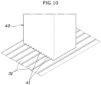
- FIG. 10 is a view illustrating yet another example of the guide wall according to embodiments of the present disclosure.
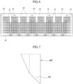
- the cooling apparatus for a power module includes a manifold cover 20 provided with an inner space through which a cooling fluid flows and in which a power module 10 is embedded, a fin plate 30 that is embedded in the manifold cover 20, is in contact with the power module 10, and is provided with a plurality of cooling fins 31 on a surface facing an inner surface of the manifold cover 20, and a guide wall 40 extending from the inner surface of the manifold cover 20 in a flow direction of the cooling fluid to form a plurality of first channels Si with first closed ends and second channels S2 with second closed ends, and the guide wall 40 formed in contact with the cooling fin 31 of the fin plate 30 so that the guide wall allows the cooling fluid to flow to the first channels Si and the second channels S2 between the cooling fins 31 of the fin plate 30 in the manifold cover 20.
- an end portion 41 of the guide wall 40 is formed to overlap the cooling fin 31 of the fin plate 30.
- the guide wall 40 is formed to extend such that the end portion 41 overlaps the cooling fin 31 of the fin plate 30, and thus contact portions of the guide wall 40 or the cooling fin 31 may be deformed in close contact with each other without a gap.
- the cooling fluid limits a flow in another direction except for a flow through the cooling fin 31. Accordingly, a cooling flow quantity is ensured because the cooling fluid flows to the first channel Si and the second channel S2, thereby improving cooling performance through the cooling fluid.
- the manifold cover 20 is formed so that the cooling fluid flows therein and is provided with an inlet 21 through which the cooling fluid is introduced and an outlet 22 through which the cooling fluid heat-exchanged with the power module 10 is discharged.
- the inlet 21 and the outlet 22 of the manifold cover 20 may be formed in series, and although the cooling fluid flows in a vertical direction in the drawings, the flow direction may be reversed therefrom and is not limited to the vertical direction.
- the power module 10 and the fin plate 30 are embedded in the inner space of the manifold cover 20, and when a flow rate is controlled by the cooling fin 31 of the fin plate 30, the cooling fluid is formed with a jet collision cooling structure, thereby increasing heat exchange efficiency with the power module 10.
- the guide wall 40 is formed on the inner surface of the manifold cover 20, and the guide wall 40 divides a plurality of cooling channels extending in a direction in which the cooling fluid flows from the inlet to the outlet. That is, the guide wall 40 extends from the inner surface of the manifold cover 20 in the flow direction of the cooling fluid and forms a plurality of first channels Si with first closed ends and a plurality of second channels S2 with second closed ends.
- the fin plate 30 is provided inside the manifold cover 20.
- the fin plate 30 is in contact with the power module 10, and the cooling fins 31 are formed so that the cooling fluid introduced from the inlet to the second channel S2 flows from the first channel Si toward the outlet.
- the manifold cover 20 may be coupled to an edge of the fin plate 30 by welding, bonding, or bolting.
- the cooling fluid is guided to the second channel S2, and since the other end of the second channel S2 is blocked, the cooling fluid forms a jet collision cooling structure through a flow along which the cooling fluid flows in the first channel Si between the cooling fins 31. Accordingly, heat exchange efficiency between the cooling fluid and the fin plate 30 is increased, thereby ensuring cooling performance of the power module 10 through the fin plate 30.
- the guide wall 40 formed on the inner surface of the manifold cover 20 is formed in contact with the cooling fin 31 of the fin plate 30.
- the cooling fluid may not pass between the cooling fins 31 and may bypass due to the gap, thereby reducing heat exchange efficiency.
- the guide wall 40 is formed in contact with the cooling fin 31 of the fin plate 30 so that the cooling fluid flows only between the cooling fins 31 when the cooling fluid flows between the first channel Si and the second channel S2, thereby ensuring heat exchange performance.
- an extension direction of the guide wall 40 and an extension direction of the cooling fin 31 intersect perpendicularly.
- the guide wall 40 extends in a longitudinal direction of the manifold cover 20
- the first channel Si and the second channel S2 extend in the longitudinal direction of the manifold cover 20 so that the cooling fluid may flow from the inlet to the outlet.
- the cooling fin 31 is formed to extend in a direction perpendicular to the extension direction of the guide wall 40, the cooling fluid may flow from the second channel S2 to the first channel S1 through the cooling fin 31. Accordingly, in a flowing process of the cooling fluid from the second channel S2 to the first channel S1, generation of turbulence having a vertical speed component is induced, and thus the jet collision cooling structure can be formed.
- the guide wall 40 may include a plurality of wall units 43 extending to divide the first channels Si and the second channels S2, first blocking units 44 connected to first sides of the wall units 43 to close first ends of the first channels S1, and second blocking units 45 connected to second sides of the wall units 43 to close second ends of the second channels S2.
- the guide wall 40 includes the plurality of wall units 43, the first blocking units 44, and the second blocking units 45.
- the cooling fluid flows through the inlet 21 of the manifold cover 20 from the second channel S2 to the first channel Si to discharge through the outlet 22.
- the guide wall 40 according to an embodiment of the present disclosure is disclosed with a form in which the wall units 43 are perpendicularly connected to the first blocking units 44 and the second blocking units 45, but is not limited thereto.
- the cooling fins 31 of the fin plate 30 are in contact with the guide wall 40 and formed together with the first channels Si and the second channels S2, and the cooling fluid flows through the cooling fins 31 to the first channels Si and the second channels S2.
- the guide wall 40 is formed to have the same separation distance between the wall units 43 and the same shape of the first and second blocking units 44 and 45 so that the flowability of the cooling fluid flowing through the first and second channels S1 and S2 may be constant.
- first blocking units 44 and the second blocking units 45 connecting the plurality of wall units 43 are formed on the guide wall 40, the first channels Si and the second channels S2 may be alternately arranged.
- the guide walls 40 are arranged such that the plurality of wall units 43 are spaced apart from each other, and the wall units 43 are connected to each other and integrated through the first and second blocking units 44 and 45.
- the first blocking unit 44 is located at one end of the wall unit 43 and connected to another adjacent wall unit 43
- the first channel Si with the second open end of the wall unit 43 may be formed.
- the second blocking unit 45 is located at the other end of the wall unit 43 and connected to another adjacent wall unit 43, the second channel S2 with the first open end of the wall unit 43 may be formed.
- the first blocking units 44 and the second blocking units 45 are alternately arranged on the wall units 43, the first channels Si and the second channels S2 are alternately formed in the guide wall 40, and the cooling fluid flows to the first channels Si and the second channels S2 to easily form the jet collision cooling structure.
- first blocking units 44 and the second blocking units 45 may be disposed apart from each other in the longitudinal direction of the wall unit 43 and are formed to be alternately arranged in the vertical direction to form a flow in which the cooling fluid repeatedly flows to the first channels Si and the second channels S2, and thus jet collision cooling may occur multiple times to further improve cooling performance.
- embodiments of the present disclosure provide an apparatus using a cooling fluid to cool a power module, and a jet collision cooling effect is applied in order to cool the power module.
- the jet collision cooling is a cooling method capable of locally obtaining a high heat transmission effect by directly spraying the cooling fluid onto a high-temperature wall surface to dissipate a heat.
- a turbulent flow rather than a laminar flow.
- a turbulence refers to a flow with a velocity component in a direction perpendicular to the flow direction, which is a flow which is not in the flow direction and is irregular and diffusible with a 3D vorticity of the top, bottom, left, and right.
- the cooling fluid flows from the inlet to form an inlet plenum which is the sum of narrow water streams.
- the manifold cover 20 is guided based on the guide wall 40 such that the cooling fluid introduced into the first channel Si or the second channel S2 is discharged through a plurality of cooling fins 31 to form micro channels.
- the cooling fluid introduced into the second channel S2 is blocked at the outlet side because a direction in which the cooling fins 31 are formed and a direction in which the guide wall 40 is formed intersect each other and flows into the first channel S1 through a gap between the cooling fins 31, and thus the turbulence is formed. Furthermore, the first channel Si is blocked at the inlet side, and the cooling fluid flows toward the outlet side and then passes through the cooling fins 31. Accordingly, the cooling fluid of the first channel S1 having irregularity and high diffusivity forms a higher jet cooling collision effect.
- guide wall 40 of embodiments of the present disclosure may be applied in various examples.
- the guide wall 40 may be formed so that the end portion 41 is cut to be inclined in the direction perpendicular to the first channel S1 and the second channel S2 to have an inclined surface.
- the guide wall 40 may be formed in the shape of a right triangle because the end portion 41 is formed to be inclined. Furthermore, the end portion 41 of the guide wall 40 may be formed to be inclined in the direction perpendicular to the first channel Si and the second channel S2, and thus may be seated on the cooling fin 31 instead of being inserted between the cooling fins 31 of the fin plate 30. Furthermore, since the end portion 41 of the guide wall 40 is formed to overlap the cooling fin 31, the guide wall 40 or the cooling fin 31 is buckled and pressed against each other without a gap, and the end portion 41 of the guide wall 40 has a right triangular shape, thereby having the shape of a consistent buckling in any one direction.
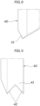
- the end portion 41 of the guide wall 40 may be formed in the shape of a wedge, since both sides thereof are cut to be inclined in the direction perpendicular to the first channel Si and the second channel S2.
- the end portion 41 of the guide wall 40 is formed in the shape of the wedge, when the guide wall 40 comes into contact with the cooling fin 31 of the fin plate 30, the end portion 41 of the guide wall 40 may be in close contact with the cooling fin 31 while buckling. That is, when the end portion 41 of the guide wall 40 is formed in the shape of the wedge, self-rigidity is ensured, and heat transmission through the fin plate 30 is smoothly performed. But since the fin plate 30 is formed of a material with low rigidity and deformable compared to the manifold cover 20, the end portion 41 of the guide wall 40 may be in close contact with the cooling fin 31 while buckling.
- a plurality of contact portions 42 having a width that gradually decreases toward the fin plate 30 are formed at the end portion 41 of the guide wall 40, thereby having multiple contact points to the cooling fin 31 of the fin plate 30.
- the plurality of contact portions 42 may have multiple contact points to the cooling fin 31 of the fin plate 30. Furthermore, the contact portion 42 is formed to gradually decrease the width of both side surfaces in the direction perpendicular to the first channel Si and the second channel S2, and thus may be seated on the cooling fin 31 instead of being inserted between the cooling fins 31 of the fin plate 30. As described above, since the plurality of contact portions 42 are formed at the end portion 41 of the guide wall 40, when a contact area with the cooling fin 31 of the fin plate 30 increases, the gap between the guide wall 40 and the cooling fin 31 may be removed.
- a contact protrusion 46 formed to extend in the extension direction of the cooling fin 31 of the fin plate 30 may be formed on the end portion 41 of the guide wall 40.
- the plurality of contact protrusions 46 are formed on the end portion 41 of the guide wall 40, multiple contact points to the cooling fin 31 of the fin plate 30 can be formed.
- the contact protrusion 46 is formed to extend in the extension direction of the cooling fin 31, the contact protrusion 46 is inserted between the cooling fins 31 of the fin plate 30 or is buckled to the cooling fin 31, and the end portion 41 of the guide wall 40 has the form of being in close contact with the cooling fin 31. Accordingly, the gap between the end portion 41 of the guide wall 40 and the cooling fin 31 of the fin plate 30 can be removed.
- the shape of the end portion 41 of the guide wall 40 described above is not limited to the above and may be applied in various embodiments.
- the jet collision cooling effect can be implemented without loss. That is, in the related art, since a structure for removing the gap between the guide wall 40 and the cooling fin 31 is not applied, the gap is generated between the guide wall 40 and the cooling fin 31, and thus the cooling effect is degraded due to a bypass of the cooling fluid.
- the bypass of the cooling fluid is prevented by removing the gap between the guide wall 40 and the cooling fin 31, thereby securing the jet collision effect the most.
- the manifold cover 20 may include a first manifold cover 20a and a second manifold cover 20b having any one of the inlet 21 and the outlet 22.
- the fin plate 30 is disposed in contact with both side surfaces of the power module 10 and includes a first fin plate 30a having a first flow hole 32a and a second fin plate 30b having a second flow hole 32b so that the cooling fluid flows between the manifold covers 20, and thus the power module 10 may be cooled at both sides.
- an exterior of the cooling apparatus is formed when the first manifold cover 20a and the second manifold cover 20b are coupled to each other.
- the first fin plate 30a and the second fin plate 30b are disposed around the power module 10 in an inner space of the first manifold cover 20a and the second manifold cover 20b, and thus both-sided cooling of the power module 10 maybe performed.
- the cooling fluid introduced through the guide wall 40 of the first manifold cover 20a and the cooling fin 31 of the first fin plate 30a flows to the first channel Si and the second channel S2 in the first manifold cover 20a to implement the jet collision cooling.
- the cooling fluid passing through the first flow hole 32a and the second flow hole 32b flows to the first channel Si and the second channel S2 in the second manifold cover 20b through the guide wall 40 of the second fin plate 30b to implement the jet collision cooling. Accordingly, the cooling of the power module 10 may be performed on both side surfaces.
- the inlet 21 or the outlet 22 may be formed at one side of each of the first manifold cover 20a and the second manifold cover 20b, and the first flow hole 32a of the first fin plate 30a and the second flow hole 32b of the second fin plate 30b may be formed at the other side.
- the inlet 21 may be formed in the first manifold cover 20a
- the outlet 22 may be formed in the second manifold cover 20b
- the inlet 21 and the outlet 22 are collinearly disposed to manufacture one manifold cover 20, and thus the first manifold cover 20a and the second manifold cover 20b may be implemented.
- the cooling fluid may form the flow of the inlet 21 - the first manifold cover 20a and the first fin plate 30a - the first flow hole 32a - the second flow hole 32b - the second manifold cover 20b and the second fin plate 30b - the outlet 22. Furthermore, in the first channel Si and the second channel S2 formed by the first manifold cover 20a and the first fin plate 30a, the jet collision cooling by a fluid flow is implemented to heat-exchange with one side surface of the power module 10.
- the jet collision cooling by the fluid flow is implemented to heat-exchange with the other side surface of the power module 10, and thus both-sided cooling of the power module 10 may be implemented.
- the cooling apparatus for a power module having the structure described above generates a vertical turbulent flow of a cooling fluid by perpendicularly spraying the cooling fluid to a heating surface through a cooling fin of a fin plate configured in the direction perpendicular to a longitudinal direction of a manifold cover, and thus the cooling efficiency is secured, and the flowability of the cooling fluid is improved to minimize flow quantity loss due to vertical turbulent flow.
- an apparatus comprising: a manifold cover provided with an inner space that defines a flow path for a cooling fluid; a power module embedded in the flow path; a fin plate embedded in the manifold cover, in contact with the power module, and comprising a plurality of cooling fins on a surface facing an inner surface of the manifold cover; and a guide wall extending from the inner surface of the manifold cover in a flow direction of the cooling fluid to define a plurality of first channels having first closed ends and second channels having second closed ends, the guide wall having an end portion in contact with the cooling fins of the fin plate to allow the cooling fluid to flow to the first channels and the second channels between the cooling fins of the fin plate in the manifold cover, wherein the end portion of the guide wall overlaps the cooling fins of the fin plate when the power module and the fin plate are mounted on the manifold cover.
- an extension direction of the guide wall perpendicularly intersects an extension direction of the cooling fins.
- the apparatus of the first or second further embodiment wherein the end portion of the guide wall is inclined in a direction perpendicular to the first channels and the second channels and has an inclined surface.
- the apparatus of one of the first to third further embodiments wherein the end portion of the guide wall comprises a plurality of contact points with the cooling fins of the fin plate in which a width of a plurality of contact portions gradually decreases toward the fin plate.
- the apparatus of one of the first to fourth further embodiments further comprising a contact protrusion disposed on the end portion of the guide wall and extending in an extension direction of the cooling fins of the fin plate.
- the guide wall comprises: a plurality of wall units extending to divide the first channels and the second channels; first blocking units connected to first sides of the wall units to close the first closed ends of the first channels; and second blocking units connected to second sides of the wall units to close the second closed ends of the second channels.
- an apparatus comprising: a power module; a manifold cover in which the power module is embedded, the manifold cover comprising a first manifold cover having an inlet and a second manifold cover having an outlet, wherein the manifold cover is provided with an inner space defining a flow path for a cooling fluid; a fin plate embedded in the manifold cover and in contact with each of two side surfaces of the power module, wherein the fin plate comprises a plurality of cooling fins on a surface facing an inner surface of the manifold cover, a first fin plate having a first flow hole defined therein, and a second fin plate having a second flow hole defined therein, wherein both sides of the power module are configured to be cooled by a flow of the cooling fluid between the first manifold cover and the second manifold cover; and a guide wall extending from the inner surface of the manifold cover in a flow direction of the cooling fluid to define a plurality of first channels having first closed ends and second channels having
- the apparatus of the seventh further embodiment wherein: the inlet is provided at a first side of the first manifold cover and the outlet is provided at a first side of the second manifold cover; and the first flow hole of the first fin plate and the second flow hole of the second fin plate are formed at second sides of the first manifold cover and the second manifold cover.
Landscapes
- Engineering & Computer Science (AREA)
- Microelectronics & Electronic Packaging (AREA)
- Physics & Mathematics (AREA)
- Thermal Sciences (AREA)
- Cooling Or The Like Of Semiconductors Or Solid State Devices (AREA)
- Cooling Or The Like Of Electrical Apparatus (AREA)
Abstract
Description
- The present disclosure relates to a cooling apparatus for a power module.
- A power module is applied to an electric vehicle or the like and controls a high voltage and a high current. Accordingly, a large amount of heat is generated, and thus an appropriate cooling is required to maintain the performance and durability of the power module. To this end, the power module is cooled through a cooling fluid, or a waste heat of the power module is used for heating in a vehicle or the like.
- In general, a cooling apparatus is connected to one side surface of a power module, and a cooling fluid flows to the cooling apparatus to cool the power module in the case of the related art. However, in the case of conventional cooling apparatuses, a cooling efficiency is not high because a simple tube structure or a fin structure which is generally used is used.
- The cooling efficiency of electric vehicles or the like is closely related to an overall energy efficiency of the vehicle, and it needs to increase the cooling efficiency for a power module through a new cooling structure.
- Furthermore, since there is no conventional method for improving the flowability of a cooling fluid for cooling a power module, the cooling performance is degraded due to a loss in the flow of the cooling fluid.
- The matters described as the background art are for the purpose of enhancing the understanding of the background of embodiments of the present disclosure and should not be taken as acknowledging that the matters correspond to the related art already known to those skilled in the art.
- The present disclosure relates to a cooling apparatus for a power module. Particular embodiments relate to a cooling apparatus for a power module which cools a power module using a cooling fluid.
- An embodiment of the present disclosure provides a cooling apparatus for a power module which generates a vertical turbulent flow of the cooling fluid by perpendicularly spraying the cooling fluid onto a heating surface through a cooling fin of the fin plate configured in a direction perpendicular to a longitudinal direction of a manifold cover, and thus cooling efficiency is secured and the flowability of the cooling fluid is improved to minimize flow quantity loss due to vertical turbulent flow.
- The cooling apparatus for a power module according to embodiments of the present disclosure includes a manifold cover provided with an inner space through which the cooling fluid flows and in which a power module is embedded, a fin plate that is embedded in the manifold cover, is in contact with the power module, and is provided with a plurality of cooling fins on a surface facing an inner surface of the manifold cover, and a guide wall extending from the inner surface of the manifold cover in a flow direction of the cooling fluid to form a plurality of first channels with first closed ends and second channels with second closed ends and having an end portion formed in contact with the cooling fins of the fin plate to allow the cooling fluid to flow to a first channel and a second channel between the cooling fins of the fin plate in the manifold cover, wherein the end portion of guide wall is formed to overlap the cooling fins of the fin plate when the power module and the fin plate are mounted on the manifold cover.
- An extension direction of the guide wall may perpendicularly intersect the extension direction of the cooling fin.
- The end portion of the guide wall may be cut to be inclined in a direction perpendicular to the first channel and the second channel and formed to have an inclined surface.
- The end portion of the guide wall may be formed so that both sides of the end portion are cut to be inclined in a direction perpendicular to the first channel and the second channel.
- The end portion of the guide wall may have a plurality of contact points to the cooling fins of the fin plate by forming a plurality of contact portions of which a width gradually decreases toward the fin plate.
- A contact protrusion formed to extend in an extension direction of the cooling fins of the fin plate may be formed on the end portion of the guide wall.
- The guide wall may include a plurality of wall units extending to divide the first channels and the second channels, first blocking units connected to first sides of the wall units to close first ends of the first channels and second blocking units connected to second sides of the wall units to close second ends of the second channels.
- The first channel and the second channel may be alternately arranged because the guide wall is provided with the first blocking units and the second blocking units connecting the plurality of wall units.
- The manifold cover may be coupled to an edge to the fin plate by welding, bonding, or bolting.
- The manifold cover may include a first manifold cover and a second manifold cover, each of which has any one of an inlet and an outlet, and the fin plate may be disposed in contact with each of two side surfaces of the power module and may include a first fin plate having a first flow hole formed therein and a second fin plate having a second flow hole formed therein so that the cooling fluid flows between the manifold covers to perform cooling on both sides of the power module.
- The inlet or outlet is formed at one side of each of the first manifold cover and the second manifold cover, and the first flow hole of the first fin plate and the second flow hole of the second fin plate are formed at the other side thereof.
-
-
FIG. 1 is a view illustrating a cooling apparatus for a power module according to embodiments of the present disclosure. -
FIG. 2 is an assembly view of the cooling apparatus for a power module shown inFIG. 1 . -
FIG. 3 is a view illustrating cooling fins of a fin plate according to embodiments of the present disclosure. -
FIG. 4 is a view illustrating a connection structure of a guide wall and the fin plate according to embodiments of the present disclosure. -
FIG. 5 is a view illustrating a guide wall of a manifold cover according to embodiments of the present disclosure. -
FIG. 6 is a view for describing a jet collision effect of the cooling apparatus for a power module according to embodiments of the present disclosure. -
FIG. 7 is a view illustrating an example of the guide wall according to embodiments of the present disclosure. -
FIG. 8 is a view illustrating another example of the guide wall according to embodiments of the present disclosure. -
FIG. 9 is a view illustrating still another example of the guide wall according to embodiments of the present disclosure. -
FIG. 10 is a view illustrating yet another example of the guide wall according to embodiments of the present disclosure. - Hereinafter, the present disclosure will be described in detail by describing disclosed embodiments of the present specification with reference to the accompanying drawings. However, regardless of the reference character, the same or similar constituent elements shall be given the same reference number and the redundant descriptions shall be omitted.
- The suffix "module" and "unit" for the constituent elements used in the description below are given or mixed for ease of description, and do not have any distinctive meaning or role in itself.
- Furthermore, in describing the embodiments of the present specification, when a specific description of the related art is deemed to obscure the essential points of the embodiments of the present specification, the detailed description will be omitted. Furthermore, the accompanying drawings are intended to facilitate the understanding of the embodiments set forth in the present specification, not to limit the technical idea of the present specification by the accompanying drawings. All alterations, equivalents, and substitutes that are included within the technical idea of the present disclosure should be understood as falling within the scope of the present disclosure.
- The ordinal number terms first, second, and so on may be used to describe various constituent elements but should not limit the meanings of these constituent elements. These terms are only used to distinguish one constituent element from another element.
- It should be understood that a constituent element, when referred to as being "connected to" or "coupled to" a different constituent element, may be directly connected or directly coupled to the different constituent element or may be coupled or connected to the different constituent element with a third constituent element disposed therebetween. In contrast, it should be understood that a constituent element, when referred to as being "directly coupled to" or "directly connected to" a different constituent element, is coupled or connected to the different constituent element without a third constituent element therebetween.
- A noun in singular form has the same meaning as nouns when used in plural form, unless it has a different meaning in context.
- It should be understood that, throughout the present specification, the term "include," "have," or the like is intended to indicate that a feature, a number, a step, an operation, a constituent element, a component, or a combination thereof is present, without precluding the possibility that one or more other features, numbers, steps, operations, constituent elements, components, or a combination thereof will be present or added.
-
FIG. 1 is a view illustrating a cooling apparatus for a power module according to embodiments of the present disclosure,FIG. 2 is an assembly view of the cooling apparatus for a power module shown inFIG. 1 ,FIG. 3 is a view illustrating a cooling fin of a fin plate according to embodiments of the present disclosure,FIG. 4 is a view illustrating a connection structure of a guide wall and the fin plate according to embodiments of the present disclosure,FIG. 5 is a view illustrating a guide wall of a manifold cover according to embodiments of the present disclosure,FIG. 6 is a view for describing a jet collision effect of the cooling apparatus for a power module according to embodiments of the present disclosure,FIG. 7 is a view illustrating an example of the guide wall according to embodiments of the present disclosure,FIG. 8 is a view illustrating another example of the guide wall according to embodiments of the present disclosure,FIG. 9 is a view illustrating still another example of the guide wall according to embodiments of the present disclosure, andFIG. 10 is a view illustrating yet another example of the guide wall according to embodiments of the present disclosure. - As illustrated in
FIGS. 1 to 5 , the cooling apparatus for a power module according to embodiments of the present disclosure includes amanifold cover 20 provided with an inner space through which a cooling fluid flows and in which apower module 10 is embedded, afin plate 30 that is embedded in themanifold cover 20, is in contact with thepower module 10, and is provided with a plurality ofcooling fins 31 on a surface facing an inner surface of themanifold cover 20, and aguide wall 40 extending from the inner surface of themanifold cover 20 in a flow direction of the cooling fluid to form a plurality of first channels Si with first closed ends and second channels S2 with second closed ends, and theguide wall 40 formed in contact with thecooling fin 31 of thefin plate 30 so that the guide wall allows the cooling fluid to flow to the first channels Si and the second channels S2 between thecooling fins 31 of thefin plate 30 in themanifold cover 20. - Particularly, in embodiments of the present disclosure, the
guide wall 40 is formed in contact with thecooling fin 31 of thefin plate 30 to form a flow so that the cooling fluid flows only through thecooling fin 31. - That is, when the
power module 10 and thefin plate 30 are mounted on themanifold cover 20, anend portion 41 of theguide wall 40 is formed to overlap thecooling fin 31 of thefin plate 30. As described above, theguide wall 40 is formed to extend such that theend portion 41 overlaps thecooling fin 31 of thefin plate 30, and thus contact portions of theguide wall 40 or thecooling fin 31 may be deformed in close contact with each other without a gap. For this reason, since theguide wall 40 is pressed against thecooling fin 31 without the gap, the cooling fluid limits a flow in another direction except for a flow through thecooling fin 31. Accordingly, a cooling flow quantity is ensured because the cooling fluid flows to the first channel Si and the second channel S2, thereby improving cooling performance through the cooling fluid. - Meanwhile, the
manifold cover 20 is formed so that the cooling fluid flows therein and is provided with aninlet 21 through which the cooling fluid is introduced and anoutlet 22 through which the cooling fluid heat-exchanged with thepower module 10 is discharged. Theinlet 21 and theoutlet 22 of themanifold cover 20 may be formed in series, and although the cooling fluid flows in a vertical direction in the drawings, the flow direction may be reversed therefrom and is not limited to the vertical direction. - The
power module 10 and thefin plate 30 are embedded in the inner space of themanifold cover 20, and when a flow rate is controlled by thecooling fin 31 of thefin plate 30, the cooling fluid is formed with a jet collision cooling structure, thereby increasing heat exchange efficiency with thepower module 10. - The
guide wall 40 is formed on the inner surface of themanifold cover 20, and theguide wall 40 divides a plurality of cooling channels extending in a direction in which the cooling fluid flows from the inlet to the outlet. That is, theguide wall 40 extends from the inner surface of themanifold cover 20 in the flow direction of the cooling fluid and forms a plurality of first channels Si with first closed ends and a plurality of second channels S2 with second closed ends. - Furthermore, the
fin plate 30 is provided inside themanifold cover 20. Thefin plate 30 is in contact with thepower module 10, and thecooling fins 31 are formed so that the cooling fluid introduced from the inlet to the second channel S2 flows from the first channel Si toward the outlet. Herein, themanifold cover 20 may be coupled to an edge of thefin plate 30 by welding, bonding, or bolting. - That is, the cooling fluid is guided to the second channel S2, and since the other end of the second channel S2 is blocked, the cooling fluid forms a jet collision cooling structure through a flow along which the cooling fluid flows in the first channel Si between the cooling
fins 31. Accordingly, heat exchange efficiency between the cooling fluid and thefin plate 30 is increased, thereby ensuring cooling performance of thepower module 10 through thefin plate 30. - Particularly, in embodiments of the present disclosure, the
guide wall 40 formed on the inner surface of themanifold cover 20 is formed in contact with the coolingfin 31 of thefin plate 30. When theguide wall 40 of themanifold cover 20 is spaced apart from the coolingfin 31 of thefin plate 30 with a gap generated therebetween, the cooling fluid may not pass between the coolingfins 31 and may bypass due to the gap, thereby reducing heat exchange efficiency. - Therefore, the
guide wall 40 is formed in contact with the coolingfin 31 of thefin plate 30 so that the cooling fluid flows only between the coolingfins 31 when the cooling fluid flows between the first channel Si and the second channel S2, thereby ensuring heat exchange performance. - To describe embodiments of the present disclosure in detail, an extension direction of the
guide wall 40 and an extension direction of the coolingfin 31 intersect perpendicularly. - That is, since the
guide wall 40 extends in a longitudinal direction of themanifold cover 20, the first channel Si and the second channel S2 extend in the longitudinal direction of themanifold cover 20 so that the cooling fluid may flow from the inlet to the outlet. Furthermore, since the coolingfin 31 is formed to extend in a direction perpendicular to the extension direction of theguide wall 40, the cooling fluid may flow from the second channel S2 to the first channel S1 through the coolingfin 31. Accordingly, in a flowing process of the cooling fluid from the second channel S2 to the first channel S1, generation of turbulence having a vertical speed component is induced, and thus the jet collision cooling structure can be formed. - In detail, the
guide wall 40 may include a plurality ofwall units 43 extending to divide the first channels Si and the second channels S2, first blockingunits 44 connected to first sides of thewall units 43 to close first ends of the first channels S1, andsecond blocking units 45 connected to second sides of thewall units 43 to close second ends of the second channels S2. - As illustrated in
FIG. 5 , theguide wall 40 includes the plurality ofwall units 43, thefirst blocking units 44, and thesecond blocking units 45. The cooling fluid flows through theinlet 21 of themanifold cover 20 from the second channel S2 to the first channel Si to discharge through theoutlet 22. Theguide wall 40 according to an embodiment of the present disclosure is disclosed with a form in which thewall units 43 are perpendicularly connected to thefirst blocking units 44 and thesecond blocking units 45, but is not limited thereto. The coolingfins 31 of thefin plate 30 are in contact with theguide wall 40 and formed together with the first channels Si and the second channels S2, and the cooling fluid flows through the coolingfins 31 to the first channels Si and the second channels S2. - Furthermore, the
guide wall 40 is formed to have the same separation distance between thewall units 43 and the same shape of the first andsecond blocking units - Furthermore, since the
first blocking units 44 and thesecond blocking units 45 connecting the plurality ofwall units 43 are formed on theguide wall 40, the first channels Si and the second channels S2 may be alternately arranged. - That is, the
guide walls 40 are arranged such that the plurality ofwall units 43 are spaced apart from each other, and thewall units 43 are connected to each other and integrated through the first andsecond blocking units first blocking unit 44 is located at one end of thewall unit 43 and connected to anotheradjacent wall unit 43, the first channel Si with the second open end of thewall unit 43 may be formed. Since thesecond blocking unit 45 is located at the other end of thewall unit 43 and connected to anotheradjacent wall unit 43, the second channel S2 with the first open end of thewall unit 43 may be formed. - Since the
first blocking units 44 and thesecond blocking units 45 are alternately arranged on thewall units 43, the first channels Si and the second channels S2 are alternately formed in theguide wall 40, and the cooling fluid flows to the first channels Si and the second channels S2 to easily form the jet collision cooling structure. - Furthermore, the
first blocking units 44 and thesecond blocking units 45 may be disposed apart from each other in the longitudinal direction of thewall unit 43 and are formed to be alternately arranged in the vertical direction to form a flow in which the cooling fluid repeatedly flows to the first channels Si and the second channels S2, and thus jet collision cooling may occur multiple times to further improve cooling performance. - Thus, embodiments of the present disclosure provide an apparatus using a cooling fluid to cool a power module, and a jet collision cooling effect is applied in order to cool the power module. That is, the jet collision cooling is a cooling method capable of locally obtaining a high heat transmission effect by directly spraying the cooling fluid onto a high-temperature wall surface to dissipate a heat. For actively implementing a jet cooling method effect, it is necessary to use a turbulent flow rather than a laminar flow. Herein, a turbulence refers to a flow with a velocity component in a direction perpendicular to the flow direction, which is a flow which is not in the flow direction and is irregular and diffusible with a 3D vorticity of the top, bottom, left, and right. When the turbulence occurs around an object, a mixing of the cooling area and the cooling fluid becomes larger, and accordingly, the cooling efficiency can be increased. Accordingly, as illustrated in
FIG. 6 , the cooling fluid flows from the inlet to form an inlet plenum which is the sum of narrow water streams. Themanifold cover 20 is guided based on theguide wall 40 such that the cooling fluid introduced into the first channel Si or the second channel S2 is discharged through a plurality of coolingfins 31 to form micro channels. That is, the cooling fluid introduced into the second channel S2 is blocked at the outlet side because a direction in which thecooling fins 31 are formed and a direction in which theguide wall 40 is formed intersect each other and flows into the first channel S1 through a gap between the coolingfins 31, and thus the turbulence is formed. Furthermore, the first channel Si is blocked at the inlet side, and the cooling fluid flows toward the outlet side and then passes through the coolingfins 31. Accordingly, the cooling fluid of the first channel S1 having irregularity and high diffusivity forms a higher jet cooling collision effect. - Meanwhile, the
guide wall 40 of embodiments of the present disclosure may be applied in various examples. - As an example, the
guide wall 40 may be formed so that theend portion 41 is cut to be inclined in the direction perpendicular to the first channel S1 and the second channel S2 to have an inclined surface. - As illustrated in
FIG. 7 , theguide wall 40 may be formed in the shape of a right triangle because theend portion 41 is formed to be inclined. Furthermore, theend portion 41 of theguide wall 40 may be formed to be inclined in the direction perpendicular to the first channel Si and the second channel S2, and thus may be seated on the coolingfin 31 instead of being inserted between the coolingfins 31 of thefin plate 30. Furthermore, since theend portion 41 of theguide wall 40 is formed to overlap the coolingfin 31, theguide wall 40 or the coolingfin 31 is buckled and pressed against each other without a gap, and theend portion 41 of theguide wall 40 has a right triangular shape, thereby having the shape of a consistent buckling in any one direction. - In another example, the
end portion 41 of theguide wall 40 may be formed in the shape of a wedge, since both sides thereof are cut to be inclined in the direction perpendicular to the first channel Si and the second channel S2. - As illustrated in
FIG. 8 , since theend portion 41 of theguide wall 40 is formed in the shape of the wedge, when theguide wall 40 comes into contact with the coolingfin 31 of thefin plate 30, theend portion 41 of theguide wall 40 may be in close contact with the coolingfin 31 while buckling. That is, when theend portion 41 of theguide wall 40 is formed in the shape of the wedge, self-rigidity is ensured, and heat transmission through thefin plate 30 is smoothly performed. But since thefin plate 30 is formed of a material with low rigidity and deformable compared to themanifold cover 20, theend portion 41 of theguide wall 40 may be in close contact with the coolingfin 31 while buckling. - In still another example, a plurality of
contact portions 42 having a width that gradually decreases toward thefin plate 30 are formed at theend portion 41 of theguide wall 40, thereby having multiple contact points to the coolingfin 31 of thefin plate 30. - As illustrated in
FIG. 9 , since the plurality ofcontact portions 42 are formed at theend portion 41 of theguide wall 40, the plurality ofcontact portions 42 may have multiple contact points to the coolingfin 31 of thefin plate 30. Furthermore, thecontact portion 42 is formed to gradually decrease the width of both side surfaces in the direction perpendicular to the first channel Si and the second channel S2, and thus may be seated on the coolingfin 31 instead of being inserted between the coolingfins 31 of thefin plate 30. As described above, since the plurality ofcontact portions 42 are formed at theend portion 41 of theguide wall 40, when a contact area with the coolingfin 31 of thefin plate 30 increases, the gap between theguide wall 40 and the coolingfin 31 may be removed. - As yet another example, a contact protrusion 46 formed to extend in the extension direction of the cooling
fin 31 of thefin plate 30 may be formed on theend portion 41 of theguide wall 40. - As illustrated in
FIG. 10 , since the plurality of contact protrusions 46 are formed on theend portion 41 of theguide wall 40, multiple contact points to the coolingfin 31 of thefin plate 30 can be formed. In particular, since the contact protrusion 46 is formed to extend in the extension direction of the coolingfin 31, the contact protrusion 46 is inserted between the coolingfins 31 of thefin plate 30 or is buckled to the coolingfin 31, and theend portion 41 of theguide wall 40 has the form of being in close contact with the coolingfin 31. Accordingly, the gap between theend portion 41 of theguide wall 40 and the coolingfin 31 of thefin plate 30 can be removed. - The shape of the
end portion 41 of theguide wall 40 described above is not limited to the above and may be applied in various embodiments. In particular, when the gap between theguide wall 40 and the coolingfin 31 is removed through each embodiment of the present disclosure, the jet collision cooling effect can be implemented without loss. That is, in the related art, since a structure for removing the gap between theguide wall 40 and the coolingfin 31 is not applied, the gap is generated between theguide wall 40 and the coolingfin 31, and thus the cooling effect is degraded due to a bypass of the cooling fluid. - As described above, in embodiments of the present disclosure, the bypass of the cooling fluid is prevented by removing the gap between the
guide wall 40 and the coolingfin 31, thereby securing the jet collision effect the most. - Meanwhile, the
manifold cover 20 according to embodiments of the present disclosure may include a firstmanifold cover 20a and asecond manifold cover 20b having any one of theinlet 21 and theoutlet 22. Thefin plate 30 is disposed in contact with both side surfaces of thepower module 10 and includes afirst fin plate 30a having afirst flow hole 32a and asecond fin plate 30b having asecond flow hole 32b so that the cooling fluid flows between the manifold covers 20, and thus thepower module 10 may be cooled at both sides. - In this way, an exterior of the cooling apparatus is formed when the first
manifold cover 20a and thesecond manifold cover 20b are coupled to each other. Thefirst fin plate 30a and thesecond fin plate 30b are disposed around thepower module 10 in an inner space of the firstmanifold cover 20a and thesecond manifold cover 20b, and thus both-sided cooling of thepower module 10 maybe performed. - In embodiments of the present disclosure, since the
inlet 21 is formed in the firstmanifold cover 20a and theoutlet 22 is formed in thesecond manifold cover 20b, the cooling fluid introduced through theguide wall 40 of the firstmanifold cover 20a and the coolingfin 31 of thefirst fin plate 30a flows to the first channel Si and the second channel S2 in the firstmanifold cover 20a to implement the jet collision cooling. The cooling fluid passing through thefirst flow hole 32a and thesecond flow hole 32b flows to the first channel Si and the second channel S2 in thesecond manifold cover 20b through theguide wall 40 of thesecond fin plate 30b to implement the jet collision cooling. Accordingly, the cooling of thepower module 10 may be performed on both side surfaces. - Herein, the
inlet 21 or theoutlet 22 may be formed at one side of each of the firstmanifold cover 20a and thesecond manifold cover 20b, and thefirst flow hole 32a of thefirst fin plate 30a and thesecond flow hole 32b of thesecond fin plate 30b may be formed at the other side. - In embodiments of the present disclosure, the
inlet 21 may be formed in the firstmanifold cover 20a, theoutlet 22 may be formed in thesecond manifold cover 20b, and theinlet 21 and theoutlet 22 are collinearly disposed to manufacture onemanifold cover 20, and thus the firstmanifold cover 20a and thesecond manifold cover 20b may be implemented. - Since the
inlet 21 and theoutlet 22 of eachmanifold cover 20 are located at one side and the flow hole of eachfin plate 30 are located at the other side, the cooling fluid may form the flow of the inlet 21 - the firstmanifold cover 20a and thefirst fin plate 30a - thefirst flow hole 32a - thesecond flow hole 32b - thesecond manifold cover 20b and thesecond fin plate 30b - theoutlet 22. Furthermore, in the first channel Si and the second channel S2 formed by the firstmanifold cover 20a and thefirst fin plate 30a, the jet collision cooling by a fluid flow is implemented to heat-exchange with one side surface of thepower module 10. In the first channel Si and the second channel S2 formed by thesecond manifold cover 20b and thesecond fin plate 30b, the jet collision cooling by the fluid flow is implemented to heat-exchange with the other side surface of thepower module 10, and thus both-sided cooling of thepower module 10 may be implemented. - The cooling apparatus for a power module having the structure described above generates a vertical turbulent flow of a cooling fluid by perpendicularly spraying the cooling fluid to a heating surface through a cooling fin of a fin plate configured in the direction perpendicular to a longitudinal direction of a manifold cover, and thus the cooling efficiency is secured, and the flowability of the cooling fluid is improved to minimize flow quantity loss due to vertical turbulent flow.
- Although specific exemplary embodiments of the present disclosure have been shown and described, it will be apparent to those skilled in the art that the present disclosure may be variously modified and changed without departing from the present disclosure provided by the appended claims.
- For example, further embodiments of the invention are as follows:
- According to a first further embodiment, there is provided an apparatus comprising: a manifold cover provided with an inner space that defines a flow path for a cooling fluid; a power module embedded in the flow path; a fin plate embedded in the manifold cover, in contact with the power module, and comprising a plurality of cooling fins on a surface facing an inner surface of the manifold cover; and a guide wall extending from the inner surface of the manifold cover in a flow direction of the cooling fluid to define a plurality of first channels having first closed ends and second channels having second closed ends, the guide wall having an end portion in contact with the cooling fins of the fin plate to allow the cooling fluid to flow to the first channels and the second channels between the cooling fins of the fin plate in the manifold cover, wherein the end portion of the guide wall overlaps the cooling fins of the fin plate when the power module and the fin plate are mounted on the manifold cover.
- According to a second further embodiment, there is provided the apparatus of the first further embodiment, wherein an extension direction of the guide wall perpendicularly intersects an extension direction of the cooling fins.
- According to a third further embodiment, there is provided the apparatus of the first or second further embodiment, wherein the end portion of the guide wall is inclined in a direction perpendicular to the first channels and the second channels and has an inclined surface.
- According to a fourth further embodiment, there is provided the apparatus of one of the first to third further embodiments, wherein the end portion of the guide wall comprises a plurality of contact points with the cooling fins of the fin plate in which a width of a plurality of contact portions gradually decreases toward the fin plate.
- According to a fifth further embodiment, there is provided the apparatus of one of the first to fourth further embodiments, further comprising a contact protrusion disposed on the end portion of the guide wall and extending in an extension direction of the cooling fins of the fin plate.
- According to a sixth further embodiment, there is provided the apparatus of one of the first to fifth further embodiments, wherein the guide wall comprises: a plurality of wall units extending to divide the first channels and the second channels; first blocking units connected to first sides of the wall units to close the first closed ends of the first channels; and second blocking units connected to second sides of the wall units to close the second closed ends of the second channels.
- According to a seventh further embodiment, there is provided an apparatus comprising: a power module; a manifold cover in which the power module is embedded, the manifold cover comprising a first manifold cover having an inlet and a second manifold cover having an outlet, wherein the manifold cover is provided with an inner space defining a flow path for a cooling fluid; a fin plate embedded in the manifold cover and in contact with each of two side surfaces of the power module, wherein the fin plate comprises a plurality of cooling fins on a surface facing an inner surface of the manifold cover, a first fin plate having a first flow hole defined therein, and a second fin plate having a second flow hole defined therein, wherein both sides of the power module are configured to be cooled by a flow of the cooling fluid between the first manifold cover and the second manifold cover; and a guide wall extending from the inner surface of the manifold cover in a flow direction of the cooling fluid to define a plurality of first channels having first closed ends and second channels having second closed ends, the guide wall having an end portion in contact with the cooling fins of the fin plate such that the cooling fluid is allowed to flow to the first channels and the second channels between the cooling fins of the fin plate in the manifold cover, wherein the end portion of the guide wall overlaps the cooling fins of the fin plate when the power module and the fin plate are mounted on the manifold cover.
- According to an eighth further embodiment, there is provided the apparatus of the seventh further embodiment, wherein: the inlet is provided at a first side of the first manifold cover and the outlet is provided at a first side of the second manifold cover; and the first flow hole of the first fin plate and the second flow hole of the second fin plate are formed at second sides of the first manifold cover and the second manifold cover.
Claims (7)
- A cooling apparatus for a power module, the cooling apparatus comprising:a manifold cover provided with an inner space that defines a flow path for a cooling fluid and in which the power module can be embedded;a fin plate embedded in the manifold cover and positioned so as to contact the power module when the power module is embedded in the flow path, the fin plate comprising a plurality of cooling fins on a surface facing an inner surface of the manifold cover; anda guide wall extending from the inner surface of the manifold cover in a flow direction of the cooling fluid to define a plurality of first channels having first closed ends and second channels having second closed ends, the guide wall having an end portion in contact with the cooling fins of the fin plate to allow the cooling fluid to flow to the first channels and the second channels between the cooling fins of the fin plate in the manifold cover, wherein the end portion of the guide wall overlaps the cooling fins of the fin plate when the power module and the fin plate are mounted on the manifold cover.
- The cooling apparatus of claim 1, wherein an extension direction of the guide wall perpendicularly intersects an extension direction of the cooling fins.
- The cooling apparatus of claim 1 or 2, wherein the end portion of the guide wall is inclined in a direction perpendicular to the first channels and the second channels and has an inclined surface.
- The cooling apparatus of one of claims 1-3, wherein both sides of the end portion of the guide wall are inclined in a direction perpendicular to the first channels and the second channels.
- The cooling apparatus of one of claims 1-4, wherein the end portion of the guide wall comprises a plurality of contact points with the cooling fins of the fin plate in which a width of a plurality of contact portions gradually decreases toward the fin plate.
- The cooling apparatus of one of claims 1-5, further comprising a contact protrusion disposed on the end portion of the guide wall and extending in an extension direction of the cooling fins of the fin plate.
- The cooling apparatus of one of claims 1-6, wherein the guide wall comprises:a plurality of wall units extending to divide the first channels and the second channels;first blocking units connected to first sides of the wall units to close the first closed ends of the first channels; andsecond blocking units connected to second sides of the wall units to close the second closed ends of the second channels.
Applications Claiming Priority (1)
| Application Number | Priority Date | Filing Date | Title |
|---|---|---|---|
| KR1020220057813A KR20230158286A (en) | 2022-05-11 | 2022-05-11 | Cooling apparatus for power module |
Publications (1)
| Publication Number | Publication Date |
|---|---|
| EP4276897A1 true EP4276897A1 (en) | 2023-11-15 |
Family
ID=84360250
Family Applications (1)
| Application Number | Title | Priority Date | Filing Date |
|---|---|---|---|
| EP22208300.8A Pending EP4276897A1 (en) | 2022-05-11 | 2022-11-18 | Cooling apparatus for power module |
Country Status (4)
| Country | Link |
|---|---|
| US (1) | US12144147B2 (en) |
| EP (1) | EP4276897A1 (en) |
| KR (1) | KR20230158286A (en) |
| CN (1) | CN117062387A (en) |
Cited By (1)
| Publication number | Priority date | Publication date | Assignee | Title |
|---|---|---|---|---|
| CN118540914A (en) * | 2024-06-05 | 2024-08-23 | 西安交通大学 | A multi-point jet topology profiled microchannel heat sink for high heat flux scenarios |
Families Citing this family (7)
| Publication number | Priority date | Publication date | Assignee | Title |
|---|---|---|---|---|
| CN115943554A (en) * | 2020-08-18 | 2023-04-07 | 日立安斯泰莫株式会社 | Power conversion device, method of manufacturing power conversion device |
| KR20230090747A (en) * | 2021-12-15 | 2023-06-22 | 현대자동차주식회사 | Cooling apparatus for both sides of power module |
| US20240064944A1 (en) * | 2022-08-17 | 2024-02-22 | Semiconductor Components Industries, Llc | Sealing method for direct liquid cooled power electronics package |
| US12122251B2 (en) * | 2022-09-28 | 2024-10-22 | BorgWarner US Technologies LLC | Systems and methods for bidirectional message architecture for inverter for electric vehicle |
| US12238907B2 (en) * | 2023-03-22 | 2025-02-25 | Ford Global Technologies, Llc | Power module assembly for a vehicle power inverter |
| JP7516634B1 (en) * | 2023-07-31 | 2024-07-16 | 古河電気工業株式会社 | Cold plate and method for manufacturing the same |
| USD1109358S1 (en) * | 2024-10-02 | 2026-01-13 | Baylor University | Universal SDS-page loader |
Citations (4)
| Publication number | Priority date | Publication date | Assignee | Title |
|---|---|---|---|---|
| EP1840962A1 (en) * | 2006-03-28 | 2007-10-03 | Delphi Technologies, Inc. | Fluid cooled electronic assembly |
| US20120325441A1 (en) * | 2011-06-23 | 2012-12-27 | Delphi Technologies, Inc. | Self circulating heat exchanger |
| GB2574632A (en) * | 2018-06-13 | 2019-12-18 | Iceotope Group Ltd | Heat sink arrangement for immersion cooling |
| US20210280498A1 (en) * | 2018-07-09 | 2021-09-09 | Lg Electronics Inc. | Cooling apparatus |
Family Cites Families (13)
| Publication number | Priority date | Publication date | Assignee | Title |
|---|---|---|---|---|
| KR19990009857A (en) | 1997-07-12 | 1999-02-05 | 오상수 | heat transmitter |
| JP4429251B2 (en) | 2005-10-17 | 2010-03-10 | 三菱電機株式会社 | Power converter |
| US8218320B2 (en) | 2010-06-29 | 2012-07-10 | General Electric Company | Heat sinks with C-shaped manifolds and millichannel cooling |
| JP5655873B2 (en) | 2012-05-09 | 2015-01-21 | 株式会社安川電機 | Inverter device |
| JP2014022490A (en) | 2012-07-17 | 2014-02-03 | Nissan Motor Co Ltd | Electric power conversion apparatus |
| US9445526B2 (en) | 2014-12-22 | 2016-09-13 | Toyota Motor Engineering & Manufacturing North America, Inc. | Modular jet impingement assemblies with passive and active flow control for electronics cooling |
| US10458719B2 (en) | 2015-01-22 | 2019-10-29 | Pimems, Inc. | High performance two-phase cooling apparatus |
| KR102413829B1 (en) | 2015-12-30 | 2022-06-29 | 한온시스템 주식회사 | heat exchanger for cooling electric element |
| KR102429990B1 (en) | 2018-10-17 | 2022-08-05 | 현대모비스 주식회사 | Power semiconductor use device |
| KR102676721B1 (en) * | 2019-04-24 | 2024-06-18 | 현대자동차주식회사 | Cooling system for power conversion device |
| US11168949B2 (en) | 2019-09-16 | 2021-11-09 | Senior Uk Limited | Heat exchangers with improved heat transfer fin insert |
| KR20230090747A (en) | 2021-12-15 | 2023-06-22 | 현대자동차주식회사 | Cooling apparatus for both sides of power module |
| KR102952381B1 (en) * | 2021-12-20 | 2026-04-13 | 현대자동차주식회사 | Cooling apparatus for power module |
-
2022
- 2022-05-11 KR KR1020220057813A patent/KR20230158286A/en active Pending
- 2022-11-15 US US17/987,199 patent/US12144147B2/en active Active
- 2022-11-18 EP EP22208300.8A patent/EP4276897A1/en active Pending
- 2022-12-02 CN CN202211539625.6A patent/CN117062387A/en active Pending
Patent Citations (4)
| Publication number | Priority date | Publication date | Assignee | Title |
|---|---|---|---|---|
| EP1840962A1 (en) * | 2006-03-28 | 2007-10-03 | Delphi Technologies, Inc. | Fluid cooled electronic assembly |
| US20120325441A1 (en) * | 2011-06-23 | 2012-12-27 | Delphi Technologies, Inc. | Self circulating heat exchanger |
| GB2574632A (en) * | 2018-06-13 | 2019-12-18 | Iceotope Group Ltd | Heat sink arrangement for immersion cooling |
| US20210280498A1 (en) * | 2018-07-09 | 2021-09-09 | Lg Electronics Inc. | Cooling apparatus |
Cited By (1)
| Publication number | Priority date | Publication date | Assignee | Title |
|---|---|---|---|---|
| CN118540914A (en) * | 2024-06-05 | 2024-08-23 | 西安交通大学 | A multi-point jet topology profiled microchannel heat sink for high heat flux scenarios |
Also Published As
| Publication number | Publication date |
|---|---|
| KR20230158286A (en) | 2023-11-20 |
| CN117062387A (en) | 2023-11-14 |
| US20230371200A1 (en) | 2023-11-16 |
| US12144147B2 (en) | 2024-11-12 |
Similar Documents
| Publication | Publication Date | Title |
|---|---|---|
| US12144147B2 (en) | Cooling apparatus for power module | |
| CN107532865B (en) | heat exchanger | |
| US11193722B2 (en) | Heat exchanger with multi-zone heat transfer surface | |
| KR101496493B1 (en) | Liquid-cooled cooling device | |
| KR20150043388A (en) | Heat exchanger insert | |
| CN107068636A (en) | Cooler and channel unit | |
| US9991188B2 (en) | Electronic component cooler | |
| EP3318832B1 (en) | Inner fin for heat exchanger | |
| US20250280509A1 (en) | Cooling device for cooling electronic components | |
| KR101775799B1 (en) | Exhaust gas heat exchanger with multiple heat exchanger channels | |
| KR20230094013A (en) | Cooling apparatus for power module | |
| US20240431071A1 (en) | Power module cooling device | |
| KR100268098B1 (en) | heat transmitter | |
| EP1022532A2 (en) | Flat tubes for use with heat exchanger and manufacturing method thereof | |
| CN118303144A (en) | Cooling device for cooling electronic components | |
| JP5162538B2 (en) | Liquid cooling system | |
| WO2016166963A1 (en) | Heat exchanger | |
| CN104677149B (en) | Oil material cooling device | |
| KR100242760B1 (en) | Plate Fin Type Heat Exchanger | |
| US20220373272A1 (en) | Heat dissipation member | |
| WO2021201019A1 (en) | Cooling device | |
| JP6926777B2 (en) | Heat exchanger | |
| CN223925542U (en) | Fin structure and heat exchanger | |
| US20260032855A1 (en) | Cooling Apparatus for Power Module | |
| KR200145266Y1 (en) | Heat exchanging device |
Legal Events
| Date | Code | Title | Description |
|---|---|---|---|
| PUAI | Public reference made under article 153(3) epc to a published international application that has entered the european phase |
Free format text: ORIGINAL CODE: 0009012 |
|
| STAA | Information on the status of an ep patent application or granted ep patent |
Free format text: STATUS: THE APPLICATION HAS BEEN PUBLISHED |
|
| AK | Designated contracting states |
Kind code of ref document: A1 Designated state(s): AL AT BE BG CH CY CZ DE DK EE ES FI FR GB GR HR HU IE IS IT LI LT LU LV MC ME MK MT NL NO PL PT RO RS SE SI SK SM TR |
|
| P01 | Opt-out of the competence of the unified patent court (upc) registered |
Effective date: 20231130 |
|
| STAA | Information on the status of an ep patent application or granted ep patent |
Free format text: STATUS: REQUEST FOR EXAMINATION WAS MADE |
|
| 17P | Request for examination filed |
Effective date: 20240515 |
|
| RBV | Designated contracting states (corrected) |
Designated state(s): AL AT BE BG CH CY CZ DE DK EE ES FI FR GB GR HR HU IE IS IT LI LT LU LV MC ME MK MT NL NO PL PT RO RS SE SI SK SM TR |