EP4276787A1 - Method and system to improve efficiency of system tests for a system having a plurality of sensors - Google Patents
Method and system to improve efficiency of system tests for a system having a plurality of sensors Download PDFInfo
- Publication number
- EP4276787A1 EP4276787A1 EP23170396.8A EP23170396A EP4276787A1 EP 4276787 A1 EP4276787 A1 EP 4276787A1 EP 23170396 A EP23170396 A EP 23170396A EP 4276787 A1 EP4276787 A1 EP 4276787A1
- Authority
- EP
- European Patent Office
- Prior art keywords
- sensor
- sensors
- test
- walk
- events
- Prior art date
- Legal status (The legal status is an assumption and is not a legal conclusion. Google has not performed a legal analysis and makes no representation as to the accuracy of the status listed.)
- Granted
Links
Images



Classifications
-
- G—PHYSICS
- G01—MEASURING; TESTING
- G01D—MEASURING NOT SPECIALLY ADAPTED FOR A SPECIFIC VARIABLE; ARRANGEMENTS FOR MEASURING TWO OR MORE VARIABLES NOT COVERED IN A SINGLE OTHER SUBCLASS; TARIFF METERING APPARATUS; MEASURING OR TESTING NOT OTHERWISE PROVIDED FOR
- G01D21/00—Measuring or testing not otherwise provided for
- G01D21/02—Measuring two or more variables by means not covered by a single other subclass
-
- G—PHYSICS
- G08—SIGNALLING
- G08B—SIGNALLING SYSTEMS, e.g. PERSONAL CALLING SYSTEMS; ORDER TELEGRAPHS; ALARM SYSTEMS
- G08B29/00—Checking or monitoring of signalling or alarm systems; Prevention or correction of operating errors, e.g. preventing unauthorised operation
- G08B29/02—Monitoring continuously signalling or alarm systems
- G08B29/04—Monitoring of the detection circuits
-
- G—PHYSICS
- G06—COMPUTING OR CALCULATING; COUNTING
- G06N—COMPUTING ARRANGEMENTS BASED ON SPECIFIC COMPUTATIONAL MODELS
- G06N20/00—Machine learning
-
- G—PHYSICS
- G08—SIGNALLING
- G08B—SIGNALLING SYSTEMS, e.g. PERSONAL CALLING SYSTEMS; ORDER TELEGRAPHS; ALARM SYSTEMS
- G08B13/00—Burglar, theft or intruder alarms
- G08B13/02—Mechanical actuation
- G08B13/10—Mechanical actuation by pressure on floors, floor coverings, stair treads, counters, or tills
-
- G—PHYSICS
- G08—SIGNALLING
- G08B—SIGNALLING SYSTEMS, e.g. PERSONAL CALLING SYSTEMS; ORDER TELEGRAPHS; ALARM SYSTEMS
- G08B29/00—Checking or monitoring of signalling or alarm systems; Prevention or correction of operating errors, e.g. preventing unauthorised operation
- G08B29/12—Checking intermittently signalling or alarm systems
- G08B29/14—Checking intermittently signalling or alarm systems checking the detection circuits
-
- G—PHYSICS
- G08—SIGNALLING
- G08B—SIGNALLING SYSTEMS, e.g. PERSONAL CALLING SYSTEMS; ORDER TELEGRAPHS; ALARM SYSTEMS
- G08B29/00—Checking or monitoring of signalling or alarm systems; Prevention or correction of operating errors, e.g. preventing unauthorised operation
- G08B29/16—Security signalling or alarm systems, e.g. redundant systems
-
- G—PHYSICS
- G08—SIGNALLING
- G08B—SIGNALLING SYSTEMS, e.g. PERSONAL CALLING SYSTEMS; ORDER TELEGRAPHS; ALARM SYSTEMS
- G08B29/00—Checking or monitoring of signalling or alarm systems; Prevention or correction of operating errors, e.g. preventing unauthorised operation
- G08B29/18—Prevention or correction of operating errors
- G08B29/185—Signal analysis techniques for reducing or preventing false alarms or for enhancing the reliability of the system
-
- H—ELECTRICITY
- H04—ELECTRIC COMMUNICATION TECHNIQUE
- H04L—TRANSMISSION OF DIGITAL INFORMATION, e.g. TELEGRAPHIC COMMUNICATION
- H04L43/00—Arrangements for monitoring or testing data switching networks
- H04L43/16—Threshold monitoring
-
- H—ELECTRICITY
- H04—ELECTRIC COMMUNICATION TECHNIQUE
- H04L—TRANSMISSION OF DIGITAL INFORMATION, e.g. TELEGRAPHIC COMMUNICATION
- H04L43/00—Arrangements for monitoring or testing data switching networks
- H04L43/50—Testing arrangements
-
- H—ELECTRICITY
- H04—ELECTRIC COMMUNICATION TECHNIQUE
- H04Q—SELECTING
- H04Q9/00—Arrangements in telecontrol or telemetry systems for selectively calling a substation from a main station, in which substation desired apparatus is selected for applying a control signal thereto or for obtaining measured values therefrom
-
- H—ELECTRICITY
- H04—ELECTRIC COMMUNICATION TECHNIQUE
- H04Q—SELECTING
- H04Q2209/00—Arrangements in telecontrol or telemetry systems
- H04Q2209/80—Arrangements in the sub-station, i.e. sensing device
- H04Q2209/84—Measuring functions
-
- H—ELECTRICITY
- H04—ELECTRIC COMMUNICATION TECHNIQUE
- H04Q—SELECTING
- H04Q2209/00—Arrangements in telecontrol or telemetry systems
- H04Q2209/80—Arrangements in the sub-station, i.e. sensing device
- H04Q2209/86—Performing a diagnostic of the sensing device
Definitions
- the present disclosure pertains generally to security systems and more particularly to improving the efficiency of security system tests.
- a security system may include a number of security sensors within a monitored area.
- the monitored area may be indoors or outdoors, for example.
- Security sensors may include a variety of different types of sensors, including but not limited to door open sensors, window open sensors, motion sensors, glass break detectors, and the like.
- a walk test is performed in which each of a plurality of security sensors are periodically triggered to ensure their operation and performance. Performing such a walk test can be time consuming. Moreover, performing a walk test can require that the security system be placed in a test mode that can leave an otherwise protected facility subject to security issues.
- communication tests are periodically performed to ensure that the security sensors are also able to communicate with a security panel and/or that the security panel is able to communicate with one or more remote devices such as a central monitoring station and/or a cloud server.
- Such communication tests can be expensive as a result of the bandwidth necessary to perform the communication tests over time, particularly when the communication tests include communication over a cellular network or the like.
- a need remains for improved methods and systems for improving the efficiency of security system tests.
- This disclosure relates generally to method and systems to improve efficiency of security system tests.
- An example may be found in a method for streamlining a sensor walk-test of a system having a plurality of sensors operatively coupled to a controller.
- the illustrative method includes storing an expected behavior of sensor events of the system. Sensor event data received by the controller over a period of time is collected, where the sensor event data is representative of sensor events reported by the plurality of sensors during the period of time. The sensor event data is compared to the expected behavior of sensor events.
- Determining which of the plurality of sensors need a sensor walk-test to verify proper operation of the sensor and which of the plurality of sensors do not need a sensor walk-test is based at least in part on the comparison of the sensor event data collected during the period of time and the expected behavior of sensor events.
- a listing of which of the plurality of sensors are determined to need a sensor walk-test to verify proper operation of the sensor is displayed on a display of a user device.
- Another example may be found in a method for streamlining communication testing of a communication path of a security system.
- the method includes scheduling execution of a plurality of communication tests in accordance with a test schedule to periodically verify communication of the communication path of the system. Operational communication along the communication path is monitored between scheduled communication tests. A timing for a next scheduled communication test is adjusted when the operational communication prior to the next scheduled communication test meets one or more communication criteria.
- the security system includes a plurality of sensors and a controller that is operably coupled to the plurality of sensors.
- the controller is configured to store an expected behavior of sensor events of the security system and to collect sensor event data received by the controller over a period of time, the sensor event data is representative of sensor events reported by the plurality of sensors during the period of time.
- the period of time may be when the security system is in a disarm state. In other cases, the period of time may be when the security system is in an armed state. In yet other cases, the period of time may be when the security system in the armed state and/or in the disarm state and in the armed state.
- the controller is configured to compare the sensor event data to the expected behavior of sensor events and to determine which of the plurality of sensors need a sensor walk-test to verify proper operation of the sensor and which of the plurality of sensors do not need a sensor walk-test based at least in part on the comparison of the sensor event data collected during the period of time and the expected behavior of sensor events.
- the controller is configured to report to a user device which of the plurality of sensors are determined to need a sensor walk-test to verify proper operation of the sensor.
- references in the specification to "an embodiment”, “some embodiments”, “other embodiments”, etc., indicate that the embodiment described may include a particular feature, structure, or characteristic, but every embodiment may not necessarily include the particular feature, structure, or characteristic. Moreover, such phrases are not necessarily referring to the same embodiment. Further, when a particular feature, structure, or characteristic is described in connection with an embodiment, it is contemplated that the feature, structure, or characteristic may be applied to other embodiments whether or not explicitly described unless clearly stated to the contrary.
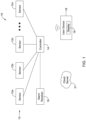
- FIG. 1 is a schematic block diagram showing an illustrative security system 10.
- the illustrative security system 10 includes a plurality of sensors 12, which are individually labeled as 12a, 12b, 12c and through 12n.
- the security system 10 may include any number of sensors 12.
- the security system 10 may include a variety of different types of sensors, such as but not limited to door open sensors, window open sensors, motion detectors and glass break detectors.
- the sensors 12 are operative coupled to a controller 14.
- the sensors 12 may communicate with the controller 14 over any desired communication protocol, including wired and wireless communication protocols.
- the controller 14 may communicate alarms with an alarm receiver 16.
- the controller 14 may communicate with a cloud-based server 21.
- the controller 14 may be located in a facility in which the sensors 12 are located. In some cases, the controller 14 may be remote from the facility in which the sensors 12 are located. The controller 14 may be manifested within a computer server, for example. In some instances, the security system 10 may be considered as including a user device 18.
- the user device 18 may, for example, be a portable device such as a laptop computer, tablet, phablet or smartphone that the user may use to communicate with the controller 14, and thus display information provided by the controller 14 on a display 19 of the user device 18 as well as to allow the controller 14 to solicit information from the user, for example.
- the user device 18 may include a separate data entry mechanism (not shown).
- the display 19 may be a touch screen display, which allows both display of information on the touch screen display as well as entering information via the touch screen display.
- the controller 14 may be configured to store an expected behavior of sensor events of the security system 10 and to collect sensor event data received by the controller 14 over a period of time.
- the sensor event data is representative of sensor events reported by the plurality of sensors 12 during the period of time.
- the period of time may be when the security system is in a disarm state. In other cases, the period of time may be when the security system is in an armed state. In yet other cases, the period of time may be when the security system in the armed state and/or in the disarm state and in the armed state.
- the expected behavior of sensor events of a particular sensor may be, for example, at least a threshold minimum number of reported sensor events during the period of time. In some cases, the expected behavior of sensor events of a particular sensor may be, for example, at least a threshold minimum number of reported sensor events but less than a threshold maximum number of reported sensor events during the period of time. In some cases, the expected behavior of sensor events of a particular sensor may be, for example, a cluster of sensor events during a first sub-period of time (e.g. 7-9AM) followed by another cluster of sensor events during a second sub-period of time (e.g. 4-5:30PM) during the period of time.
- a first sub-period of time e.g. 7-9AM
- another cluster of sensor events during a second sub-period of time e.g. 4-5:30PM
- the expected behavior of sensor events may be a combination of sensor events reported by two or more sensors.
- the expected behavior of sensor events may include a sensor event reported by a first sensor, followed by a sensor event reported by a second sensor within 10 seconds of the sensor event reported by the first sensor.
- the expected behavior of sensor events of the security system 10 may be learned over a training period of time using machine learning.
- the controller 14 may be configured to compare the sensor event data to the expected behavior of sensor events and to determine which of the plurality of sensors 12 need a sensor walk-test to verify proper operation of the sensor 12 and which of the plurality of sensors 12 do not need a sensor walk-test based at least in part on the comparison of the sensor event data collected during the period of time and the expected behavior of sensor events. For example, if a particular sensor has not reported any sensor events during the period of time, it may be determined that a walk-test is need to verify the proper operation of the sensor.
- a second sensor is expected to generate a sensor event after a first sensor generates a sensor event, but the second sensor does not generate a sensor event after the first sensor generates a sensor event during the period of time, it may be determined that a walk-test is need to verify the proper operation of the second sensor. However, if the second sensor does generate a sensor event after the first sensor generates a sensor event each time during the period of time (even when the security system is in a disarm state), it may be determined that a walk-test is not needed to verify the proper operation of the second sensor. These are just examples. In some cases, the controller 14 may be configured to report to the user device 18 which of the plurality of sensors 12 are determined to need a sensor walk-test to verify proper operation of the sensor 12.
- the controller 14 may be configured to determine a confidence level in the determination of which of the plurality of sensors 12 need a sensor walk-test and/or which of the plurality of sensors 12 do not need a sensor walk-test based at least in part on a deviation of the sensor event data collected during the period of time and the expected behavior of sensor events. In some cases, the controller 14 may also be configured to report the confidence level to the user device 18 so that the user can see the confidence level.
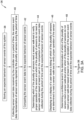
- FIG. 2 is a flow diagram showing an illustrative method 20 for streamlining a sensor walk-test of a system (such as the security system 10) having a plurality of sensors (such as the plurality of sensors 12) operatively coupled to a controller (such as the controller 14). Rather than requiring a walk-test for every sensor of the system, it is contemplated that a walk-test may not be necessary for at least some of the sensors of the system, thereby streamlining the sensor walk-test of the system.
- the illustrative method 20 includes storing an expected behavior of sensor events of the system, as indicated at block 22.
- the sensors events may include one or more trigger events that were sensed and reported by one or more of the plurality of sensors.
- the sensor events may additionally or alternatively include one or more sensed values that were sensed and reported by one or more of the plurality of sensors.
- the expected behavior of sensors events of the system may be learned over a training period of time using machine learning.
- the expected behavior of sensor events for a particular one of the plurality of sensors may include receiving by the controller at least a threshold number of sensor events reported by the particular one of the plurality of sensors during the period of time.
- the expected behavior of sensor events for a particular one of the plurality of sensors may, for example, include receiving by the controller a temporal pattern of sensor events reported by the particular one of the plurality of sensors during the period of time.
- the expected behavior of sensor events for a particular one of the plurality of sensors may include receiving by the controller one or more sensor events reported by the particular one of the plurality of sensors that are correlated with one or more sensor events reported by one or more other of the plurality of sensors during the period of time.
- Sensor event data received by the controller is collected over a period of time.
- the sensor event data is representative of sensor events reported by the plurality of sensors during the period of time, as indicated at block 24.
- the sensor event data is compared to the expected behavior of sensor events, as indicated at block 26.
- a determination is made as to which of the plurality of sensors need a sensor walk-test to verify proper operation of the sensor and which of the plurality of sensors do not need a sensor walk-test based at least in part on the comparison of the sensor event data collected during the period of time and the expected behavior of sensor events, as indicated at block 28.
- a listing of which of the plurality of sensors are determined to need a sensor walk-test to verify proper operation of the sensor is displayed on a display (such as the display 19) of the user device 18, as indicated at block 30.
- the method 20 may also include displaying on the display of the user device which of the plurality of sensors are determined to not need a sensor walk-test to verify proper operation of the sensor, as indicated at block 34.
- the method 20 may also include displaying on the display of the user device a geo-location on a floor plan of each of the plurality of sensors determined to need a sensor walk-test, as indicated at block 34.
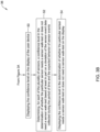
- Figure 3A and 3B are flow diagrams that together show an illustrative method 36 for streamlining a sensor walk-test of a system (such as the security system 10) having a plurality of sensors (such as the plurality of sensors 12) operatively coupled to a controller (such as the controller 14).
- the illustrative method 36 includes storing an expected behavior of sensor events of the system, as indicated at block 38.
- the sensors events may include one or more trigger events that were sensed and reported by one or more of the plurality of sensors.
- the sensor events may additionally or alternatively include one or more sensed values that were sensed and reported by one or more of the plurality of sensors.
- the expected behavior of sensors events of the system may be learned over a training period of time using machine learning.
- the expected behavior of sensor events for a particular one of the plurality of sensors may include receiving by the controller at least a threshold number of sensor events reported by the particular one of the plurality of sensors during the period of time.
- the expected behavior of sensor events for a particular one of the plurality of sensors may, for example, include receiving by the controller a temporal pattern of sensor events reported by the particular one of the plurality of sensors during the period of time.
- the expected behavior of sensor events for a particular one of the plurality of sensors may include receiving by the controller one or more sensor events reported by the particular one of the plurality of sensors that are correlated with one or more sensor events reported by one or more other of the plurality of sensors during the period of time.
- Sensor event data received by the controller is collected over a period of time.
- the sensor event data is representative of sensor events reported by the plurality of sensors during the period of time, as indicated at block 40.
- the sensor event data is compared to the expected behavior of sensor events, as indicated at block 42.
- a determination is made as to which of the plurality of sensors need a sensor walk-test to verify proper operation of the sensor and which of the plurality of sensors do not need a sensor walk-test based at least in part on the comparison of the sensor event data collected during the period of time and the expected behavior of sensor events, as indicated at block 44.
- a listing of which of the plurality of sensors are determined to need a sensor walk-test to verify proper operation of the sensor is displayed on a display (such as the display 19) of the user device 18, as indicated at block 46.
- the illustrative method 36 may include determining a confidence level in the determination of which of the plurality of sensors need a sensor walk-test and/or which of the plurality of sensors do not need a sensor walk-test based at least in part on a deviation of the sensor event data collected during the period of time and the expected behavior of sensor events, as indicated at block 48.
- the method 36 may include displaying the confidence level on the display of the user device, as indicated at block 50.
- the method 36 may further include determining, for each of the plurality of sensors, a confidence level in the determination of whether the particular sensor needs a sensor walk-test or does not need a sensor walk-test based at least in part on a deviation of the sensor event data collected during the period of time and the expected behavior of sensor events, as indicated at block 52.
- the confidence level in the determination of whether the particular sensor needs a sensor walk-test or does not need a sensor walk-test may be displayed on the display, as indicated at block 54.
- Figure 4 is a flow diagram showing an illustrative method 56 for streamlining communication testing of a communication path of a system (such as the security system 10).
- the method 56 includes scheduling execution of a plurality of communication tests in accordance with a test schedule to periodically verify communication of the communication path of the system, as indicated at block 58.
- the system includes a plurality of sensors that are operatively coupled to the controller via the alarm receiver, and the communication path is between the alarm receiver and the controller.
- the system includes a plurality of sensors that are operatively coupled to the controller, with the controller operatively coupled to a cloud server, and the communication path is between the controller and the cloud server.
- Operational communication along the communication path is monitored between scheduled communication tests, as indicated at block 60.
- Operational communication includes communication that occurs along the communication path(s) during normal system operation of the security system (e.g. while the security system is up and running in the facility, whether in an armed and/or disarmed state).
- a timing for a next scheduled communication test is adjusted when the operational communication prior to the next scheduled communication test meets one or more communication criteria, as indicated at block 62.
- the plurality of communication tests may include a plurality of scheduled ping-pong tests between the controller and the cloud server, wherein the scheduled ping-pong tests are scheduled to occur at scheduled frequency, and wherein adjusting the timing for the next scheduled communication test may include dynamically adjusting the scheduled frequency or test times depending on the number and/or frequency of communications that have occurred across that communication path during normal system operation of the security system.
- adjusting the timing for a next scheduled communication test may include skipping the next scheduled communication test when the operational communication prior to the next scheduled communication meets the one or more communication criteria.
- the one or more communication criteria may include at least a threshold level of operational communication along the communication path over a predetermined period of time.
- FIG. 5 is a schematic block diagram of an illustrative security system 64 that may be considered as being an example of the security system 10.
- the security system 64 includes a plurality of sensors 66, individually labeled as 66a, 66b, 66c and 66d. While a total of four sensors 66 are shown, it will be appreciated that this is merely illustrative, as the security system 64 may include any number of sensors 66.
- the security sensors 66 are operatively coupled with a control panel 68 such that sensor data is provided from the sensors 66 to the control panel 68. In some instances, the control panel 68 may be considered as an example of the controller 14.
- the control panel 68 may include a cellular module 70 that allows the control panel 68 to communicate bidirectionally with a cloud-based server 72 and with any of a number of central monitoring stations (CMS) 74, individually labeled as 74a and 74b.
- CMS central monitoring stations
- the control panel 68 may also be configured to communicate over a network with a security panel console 76.
- the control panel 68 and the security panel console 76 may communicate over a FieldBus network.
- the security panel console 76 may be considered as being an example of the user device 18.
- FIG 6 is a schematic view of an illustrative floor plan 78.
- the floor plan 78 may be considered as representing part of an office space, with individual offices, a conference room, restrooms, a small kitchen and a lobby, for example.
- the floor plan 78 identifies each room or space as being part of a zone, labeled Zone 1 through Zone 10.
- Zone 1 includes a PIR (motion) sensor 80.
- Zone 2 includes a PIR sensor 82.
- Zone 3 includes a door close sensor 84.
- the floor plan 78 also shows a security console 86.
- the security console 86 may guide the user as to where the sensors are that need to be manually tested (e.g. need a walk-test), and may include a listing of the sensors that do not need to be manually tested (e.g. do not need a walk-test).
- Figures 7A and 7B are screen shots that may be displayed via the security console 86 in guiding the user through a walk test.
- the security console 86 is represented as a user's mobile device (e.g. smartphone).
- Figure 7A shows a screen 88 that informs the user that Area 3, with a total of 100 zones, is ready to test.
- the screen 88 includes a START TEST button 90 that the user may select in order to start the walk-test.
- Figure 7B shows a screen 92 that may be displayed via the security console 86 once the user has selected the START TEST button 90.
- the screen 92 includes a NOT TESTED tab 94 and a TESTED tab 96.
- the sensors that are listed when the NOT TESTED tab 94 is selected include the sensors that need a walk-test.
- the TESTED tab 96 has been selected.
- the screen 92 includes a listing 98 showing all of the sensors that have been automatically determined to not need a walk-test.
- the listing 98 includes an identification of each area or zone, along with a count on how many times the sensor(s) were determined to have been triggered, along with a confidence level in that determination (e.g.
- Zone 1 the system has determined that the sensor in Zone 1 was triggered nine (9) times during a prior period of time while the security system was under normal system operation, and the confidence level in the determination that the sensor does not need a sensor walk-test is HIGH.
- Zone 4 that system has determined that the sensor was triggered only two (2) times during the prior period of time while the security system was under normal system operation, and the confidence level in the determination that the sensor does not need a sensor walk-test is LOW. In this latter case, and because of the LOW confidence level, a walk-test may or may not be conducted for the sensor(s) in Zone 4 at the discretion of the testing personnel.
- Figure 8 is a flow diagram showing an illustrative method 100 for creating the historical tested zones map.
- the method 100 includes obtaining security system events, as indicated at block 102.
- the events are filtered to obtain zone-specific data, as indicated at block 104.
- Specific zones may be grouped together for a predefined time period, as indicated at block 106.
- Corresponding confidence levels may be determined, as indicated at block 108.
- a listing of zones tested may be prepared, as indicated at block 110.
- the listing of zones tested may include the determined confidence level, the number of triggers, the period between triggers, and the last trigger time.
- An example listing of zones is shown at 112.
- Test status may be determined, as indicated at block 114. The test status is queried at decision block 116. If all have been tested, control passes to block 118, and the walk test is done. If only some are tested, control passes to block 120, and a list of remaining sensors to be test is provided, as indicated at block 120.
Landscapes
- Engineering & Computer Science (AREA)
- Physics & Mathematics (AREA)
- General Physics & Mathematics (AREA)
- Computer Security & Cryptography (AREA)
- Computer Networks & Wireless Communication (AREA)
- Signal Processing (AREA)
- Theoretical Computer Science (AREA)
- Software Systems (AREA)
- Data Mining & Analysis (AREA)
- Evolutionary Computation (AREA)
- Medical Informatics (AREA)
- Computer Vision & Pattern Recognition (AREA)
- Computing Systems (AREA)
- General Engineering & Computer Science (AREA)
- Mathematical Physics (AREA)
- Artificial Intelligence (AREA)
- Alarm Systems (AREA)
Abstract
Description
- The present disclosure pertains generally to security systems and more particularly to improving the efficiency of security system tests.
- A security system may include a number of security sensors within a monitored area. The monitored area may be indoors or outdoors, for example. Security sensors may include a variety of different types of sensors, including but not limited to door open sensors, window open sensors, motion sensors, glass break detectors, and the like. In many security systems, a walk test is performed in which each of a plurality of security sensors are periodically triggered to ensure their operation and performance. Performing such a walk test can be time consuming. Moreover, performing a walk test can require that the security system be placed in a test mode that can leave an otherwise protected facility subject to security issues. In many security systems, communication tests are periodically performed to ensure that the security sensors are also able to communicate with a security panel and/or that the security panel is able to communicate with one or more remote devices such as a central monitoring station and/or a cloud server. Such communication tests can be expensive as a result of the bandwidth necessary to perform the communication tests over time, particularly when the communication tests include communication over a cellular network or the like. A need remains for improved methods and systems for improving the efficiency of security system tests.
- This disclosure relates generally to method and systems to improve efficiency of security system tests. An example may be found in a method for streamlining a sensor walk-test of a system having a plurality of sensors operatively coupled to a controller. The illustrative method includes storing an expected behavior of sensor events of the system. Sensor event data received by the controller over a period of time is collected, where the sensor event data is representative of sensor events reported by the plurality of sensors during the period of time. The sensor event data is compared to the expected behavior of sensor events. Determining which of the plurality of sensors need a sensor walk-test to verify proper operation of the sensor and which of the plurality of sensors do not need a sensor walk-test is based at least in part on the comparison of the sensor event data collected during the period of time and the expected behavior of sensor events. A listing of which of the plurality of sensors are determined to need a sensor walk-test to verify proper operation of the sensor is displayed on a display of a user device.
- Another example may be found in a method for streamlining communication testing of a communication path of a security system. The method includes scheduling execution of a plurality of communication tests in accordance with a test schedule to periodically verify communication of the communication path of the system. Operational communication along the communication path is monitored between scheduled communication tests. A timing for a next scheduled communication test is adjusted when the operational communication prior to the next scheduled communication test meets one or more communication criteria.
- Another example may be found in a security system. The security system includes a plurality of sensors and a controller that is operably coupled to the plurality of sensors. The controller is configured to store an expected behavior of sensor events of the security system and to collect sensor event data received by the controller over a period of time, the sensor event data is representative of sensor events reported by the plurality of sensors during the period of time. In some cases, the period of time may be when the security system is in a disarm state. In other cases, the period of time may be when the security system is in an armed state. In yet other cases, the period of time may be when the security system in the armed state and/or in the disarm state and in the armed state.
- The controller is configured to compare the sensor event data to the expected behavior of sensor events and to determine which of the plurality of sensors need a sensor walk-test to verify proper operation of the sensor and which of the plurality of sensors do not need a sensor walk-test based at least in part on the comparison of the sensor event data collected during the period of time and the expected behavior of sensor events. The controller is configured to report to a user device which of the plurality of sensors are determined to need a sensor walk-test to verify proper operation of the sensor.
- The preceding summary is provided to facilitate an understanding of some of the features of the present disclosure and is not intended to be a full description. A full appreciation of the disclosure can be gained by taking the entire specification, claims, drawings, and abstract as a whole.
- The disclosure may be more completely understood in consideration of the following description of various illustrative embodiments of the disclosure in connection with the accompanying drawings, in which:
-
Figure 1 is a schematic block diagram of an illustrative security system; -
Figure 2 is a flow diagram showing an illustrative method; -
Figures 3A and3B are flow diagrams that together show an illustrative method; -
Figure 4 is a flow diagram showing an illustrative method; -
Figure 5 is a schematic block diagram of an illustrative security system; -
Figure 6 is a schematic floor plan showing an example security system; -
Figures 7A and 7B are screen shots showing illustrative screens that may be displayed; and -
Figure 8 is a flow diagram showing an illustrative method. - While the disclosure is amenable to various modifications and alternative forms, specifics thereof have been shown by way of example in the drawings and will be described in detail. It should be understood, however, that the intention is not to limit aspects of the disclosure to the particular illustrative embodiments described. On the contrary, the intention is to cover all modifications, equivalents, and alternatives falling within the spirit and scope of the disclosure.
- The following description should be read with reference to the drawings wherein like reference numerals indicate like elements. The drawings, which are not necessarily to scale, are not intended to limit the scope of the disclosure. In some of the figures, elements not believed necessary to an understanding of relationships among illustrated components may have been omitted for clarity.
- All numbers are herein assumed to be modified by the term "about", unless the content clearly dictates otherwise. The recitation of numerical ranges by endpoints includes all numbers subsumed within that range (e.g., 1 to 5 includes 1, 1.5, 2, 2.75, 3, 3.80, 4, and 5).
- As used in this specification and the appended claims, the singular forms "a", "an", and "the" include the plural referents unless the content clearly dictates otherwise. As used in this specification and the appended claims, the term "or" is generally employed in its sense including "and/or" unless the content clearly dictates otherwise.
- It is noted that references in the specification to "an embodiment", "some embodiments", "other embodiments", etc., indicate that the embodiment described may include a particular feature, structure, or characteristic, but every embodiment may not necessarily include the particular feature, structure, or characteristic. Moreover, such phrases are not necessarily referring to the same embodiment. Further, when a particular feature, structure, or characteristic is described in connection with an embodiment, it is contemplated that the feature, structure, or characteristic may be applied to other embodiments whether or not explicitly described unless clearly stated to the contrary.
-
Figure 1 is a schematic block diagram showing anillustrative security system 10. Theillustrative security system 10 includes a plurality ofsensors 12, which are individually labeled as 12a, 12b, 12c and through 12n. Thesecurity system 10 may include any number ofsensors 12. Thesecurity system 10 may include a variety of different types of sensors, such as but not limited to door open sensors, window open sensors, motion detectors and glass break detectors. Thesensors 12 are operative coupled to acontroller 14. Thesensors 12 may communicate with thecontroller 14 over any desired communication protocol, including wired and wireless communication protocols. In some cases, thecontroller 14 may communicate alarms with analarm receiver 16. In some cases, thecontroller 14 may communicate with a cloud-basedserver 21. - The
controller 14 may be located in a facility in which thesensors 12 are located. In some cases, thecontroller 14 may be remote from the facility in which thesensors 12 are located. Thecontroller 14 may be manifested within a computer server, for example. In some instances, thesecurity system 10 may be considered as including auser device 18. Theuser device 18 may, for example, be a portable device such as a laptop computer, tablet, phablet or smartphone that the user may use to communicate with thecontroller 14, and thus display information provided by thecontroller 14 on adisplay 19 of theuser device 18 as well as to allow thecontroller 14 to solicit information from the user, for example. Theuser device 18 may include a separate data entry mechanism (not shown). In some cases, thedisplay 19 may be a touch screen display, which allows both display of information on the touch screen display as well as entering information via the touch screen display. - In some cases, the
controller 14 may be configured to store an expected behavior of sensor events of thesecurity system 10 and to collect sensor event data received by thecontroller 14 over a period of time. The sensor event data is representative of sensor events reported by the plurality ofsensors 12 during the period of time. In some cases, the period of time may be when the security system is in a disarm state. In other cases, the period of time may be when the security system is in an armed state. In yet other cases, the period of time may be when the security system in the armed state and/or in the disarm state and in the armed state. - In some cases, the expected behavior of sensor events of a particular sensor may be, for example, at least a threshold minimum number of reported sensor events during the period of time. In some cases, the expected behavior of sensor events of a particular sensor may be, for example, at least a threshold minimum number of reported sensor events but less than a threshold maximum number of reported sensor events during the period of time. In some cases, the expected behavior of sensor events of a particular sensor may be, for example, a cluster of sensor events during a first sub-period of time (e.g. 7-9AM) followed by another cluster of sensor events during a second sub-period of time (e.g. 4-5:30PM) during the period of time. In some cases, the expected behavior of sensor events may be a combination of sensor events reported by two or more sensors. For example, the expected behavior of sensor events may include a sensor event reported by a first sensor, followed by a sensor event reported by a second sensor within 10 seconds of the sensor event reported by the first sensor. In some instances, the expected behavior of sensor events of the
security system 10 may be learned over a training period of time using machine learning. - The
controller 14 may be configured to compare the sensor event data to the expected behavior of sensor events and to determine which of the plurality ofsensors 12 need a sensor walk-test to verify proper operation of thesensor 12 and which of the plurality ofsensors 12 do not need a sensor walk-test based at least in part on the comparison of the sensor event data collected during the period of time and the expected behavior of sensor events. For example, if a particular sensor has not reported any sensor events during the period of time, it may be determined that a walk-test is need to verify the proper operation of the sensor. Likewise, if a second sensor is expected to generate a sensor event after a first sensor generates a sensor event, but the second sensor does not generate a sensor event after the first sensor generates a sensor event during the period of time, it may be determined that a walk-test is need to verify the proper operation of the second sensor. However, if the second sensor does generate a sensor event after the first sensor generates a sensor event each time during the period of time (even when the security system is in a disarm state), it may be determined that a walk-test is not needed to verify the proper operation of the second sensor. These are just examples. In some cases, thecontroller 14 may be configured to report to theuser device 18 which of the plurality ofsensors 12 are determined to need a sensor walk-test to verify proper operation of thesensor 12. - In some instances, the
controller 14 may be configured to determine a confidence level in the determination of which of the plurality ofsensors 12 need a sensor walk-test and/or which of the plurality ofsensors 12 do not need a sensor walk-test based at least in part on a deviation of the sensor event data collected during the period of time and the expected behavior of sensor events. In some cases, thecontroller 14 may also be configured to report the confidence level to theuser device 18 so that the user can see the confidence level. -
Figure 2 is a flow diagram showing anillustrative method 20 for streamlining a sensor walk-test of a system (such as the security system 10) having a plurality of sensors (such as the plurality of sensors 12) operatively coupled to a controller (such as the controller 14). Rather than requiring a walk-test for every sensor of the system, it is contemplated that a walk-test may not be necessary for at least some of the sensors of the system, thereby streamlining the sensor walk-test of the system. Theillustrative method 20 includes storing an expected behavior of sensor events of the system, as indicated atblock 22. In some cases, the sensors events may include one or more trigger events that were sensed and reported by one or more of the plurality of sensors. The sensor events may additionally or alternatively include one or more sensed values that were sensed and reported by one or more of the plurality of sensors. - In some cases, the expected behavior of sensors events of the system may be learned over a training period of time using machine learning. In some instances, the expected behavior of sensor events for a particular one of the plurality of sensors may include receiving by the controller at least a threshold number of sensor events reported by the particular one of the plurality of sensors during the period of time. The expected behavior of sensor events for a particular one of the plurality of sensors may, for example, include receiving by the controller a temporal pattern of sensor events reported by the particular one of the plurality of sensors during the period of time. In some instances, the expected behavior of sensor events for a particular one of the plurality of sensors may include receiving by the controller one or more sensor events reported by the particular one of the plurality of sensors that are correlated with one or more sensor events reported by one or more other of the plurality of sensors during the period of time.
- Sensor event data received by the controller is collected over a period of time. The sensor event data is representative of sensor events reported by the plurality of sensors during the period of time, as indicated at
block 24. The sensor event data is compared to the expected behavior of sensor events, as indicated atblock 26. A determination is made as to which of the plurality of sensors need a sensor walk-test to verify proper operation of the sensor and which of the plurality of sensors do not need a sensor walk-test based at least in part on the comparison of the sensor event data collected during the period of time and the expected behavior of sensor events, as indicated atblock 28. - A listing of which of the plurality of sensors are determined to need a sensor walk-test to verify proper operation of the sensor is displayed on a display (such as the display 19) of the
user device 18, as indicated atblock 30. In some cases, themethod 20 may also include displaying on the display of the user device which of the plurality of sensors are determined to not need a sensor walk-test to verify proper operation of the sensor, as indicated atblock 34. Themethod 20 may also include displaying on the display of the user device a geo-location on a floor plan of each of the plurality of sensors determined to need a sensor walk-test, as indicated atblock 34. -
Figure 3A and3B are flow diagrams that together show anillustrative method 36 for streamlining a sensor walk-test of a system (such as the security system 10) having a plurality of sensors (such as the plurality of sensors 12) operatively coupled to a controller (such as the controller 14). Theillustrative method 36 includes storing an expected behavior of sensor events of the system, as indicated atblock 38. In some cases, the sensors events may include one or more trigger events that were sensed and reported by one or more of the plurality of sensors. The sensor events may additionally or alternatively include one or more sensed values that were sensed and reported by one or more of the plurality of sensors. - In some cases, the expected behavior of sensors events of the system may be learned over a training period of time using machine learning. In some instances, the expected behavior of sensor events for a particular one of the plurality of sensors may include receiving by the controller at least a threshold number of sensor events reported by the particular one of the plurality of sensors during the period of time. The expected behavior of sensor events for a particular one of the plurality of sensors may, for example, include receiving by the controller a temporal pattern of sensor events reported by the particular one of the plurality of sensors during the period of time. In some instances, the expected behavior of sensor events for a particular one of the plurality of sensors may include receiving by the controller one or more sensor events reported by the particular one of the plurality of sensors that are correlated with one or more sensor events reported by one or more other of the plurality of sensors during the period of time.
- Sensor event data received by the controller is collected over a period of time. The sensor event data is representative of sensor events reported by the plurality of sensors during the period of time, as indicated at
block 40. The sensor event data is compared to the expected behavior of sensor events, as indicated atblock 42. A determination is made as to which of the plurality of sensors need a sensor walk-test to verify proper operation of the sensor and which of the plurality of sensors do not need a sensor walk-test based at least in part on the comparison of the sensor event data collected during the period of time and the expected behavior of sensor events, as indicated atblock 44. A listing of which of the plurality of sensors are determined to need a sensor walk-test to verify proper operation of the sensor is displayed on a display (such as the display 19) of theuser device 18, as indicated atblock 46. - The
illustrative method 36 may include determining a confidence level in the determination of which of the plurality of sensors need a sensor walk-test and/or which of the plurality of sensors do not need a sensor walk-test based at least in part on a deviation of the sensor event data collected during the period of time and the expected behavior of sensor events, as indicated atblock 48. Continuing withFigure 3B , themethod 36 may include displaying the confidence level on the display of the user device, as indicated atblock 50. In some cases, themethod 36 may further include determining, for each of the plurality of sensors, a confidence level in the determination of whether the particular sensor needs a sensor walk-test or does not need a sensor walk-test based at least in part on a deviation of the sensor event data collected during the period of time and the expected behavior of sensor events, as indicated atblock 52. The confidence level in the determination of whether the particular sensor needs a sensor walk-test or does not need a sensor walk-test may be displayed on the display, as indicated atblock 54. -
Figure 4 is a flow diagram showing anillustrative method 56 for streamlining communication testing of a communication path of a system (such as the security system 10). Themethod 56 includes scheduling execution of a plurality of communication tests in accordance with a test schedule to periodically verify communication of the communication path of the system, as indicated atblock 58. In some cases, the system includes a plurality of sensors that are operatively coupled to the controller via the alarm receiver, and the communication path is between the alarm receiver and the controller. In some cases, the system includes a plurality of sensors that are operatively coupled to the controller, with the controller operatively coupled to a cloud server, and the communication path is between the controller and the cloud server. - Operational communication along the communication path is monitored between scheduled communication tests, as indicated at
block 60. Operational communication includes communication that occurs along the communication path(s) during normal system operation of the security system (e.g. while the security system is up and running in the facility, whether in an armed and/or disarmed state). A timing for a next scheduled communication test is adjusted when the operational communication prior to the next scheduled communication test meets one or more communication criteria, as indicated atblock 62. - In some cases, the plurality of communication tests may include a plurality of scheduled ping-pong tests between the controller and the cloud server, wherein the scheduled ping-pong tests are scheduled to occur at scheduled frequency, and wherein adjusting the timing for the next scheduled communication test may include dynamically adjusting the scheduled frequency or test times depending on the number and/or frequency of communications that have occurred across that communication path during normal system operation of the security system. In some cases, adjusting the timing for a next scheduled communication test may include skipping the next scheduled communication test when the operational communication prior to the next scheduled communication meets the one or more communication criteria. As an example, the one or more communication criteria may include at least a threshold level of operational communication along the communication path over a predetermined period of time.
-
Figure 5 is a schematic block diagram of anillustrative security system 64 that may be considered as being an example of thesecurity system 10. Features ascribed to thesecurity system 64 may be included in thesecurity system 10. Features ascribed to thesecurity system 10 may be included in thesecurity system 64. Thesecurity system 64 includes a plurality ofsensors 66, individually labeled as 66a, 66b, 66c and 66d. While a total of foursensors 66 are shown, it will be appreciated that this is merely illustrative, as thesecurity system 64 may include any number ofsensors 66. Thesecurity sensors 66 are operatively coupled with acontrol panel 68 such that sensor data is provided from thesensors 66 to thecontrol panel 68. In some instances, thecontrol panel 68 may be considered as an example of thecontroller 14. - The
control panel 68 may include acellular module 70 that allows thecontrol panel 68 to communicate bidirectionally with a cloud-basedserver 72 and with any of a number of central monitoring stations (CMS) 74, individually labeled as 74a and 74b. In some cases, thecontrol panel 68 may also be configured to communicate over a network with asecurity panel console 76. As an example, thecontrol panel 68 and thesecurity panel console 76 may communicate over a FieldBus network. Thesecurity panel console 76 may be considered as being an example of theuser device 18. -
Figure 6 is a schematic view of anillustrative floor plan 78. Thefloor plan 78 may be considered as representing part of an office space, with individual offices, a conference room, restrooms, a small kitchen and a lobby, for example. Thefloor plan 78 identifies each room or space as being part of a zone, labeledZone 1 throughZone 10.Zone 1 includes a PIR (motion)sensor 80.Zone 2 includes aPIR sensor 82.Zone 3 includes a doorclose sensor 84. Thefloor plan 78 also shows asecurity console 86. Thesecurity console 86 may guide the user as to where the sensors are that need to be manually tested (e.g. need a walk-test), and may include a listing of the sensors that do not need to be manually tested (e.g. do not need a walk-test). -
Figures 7A and 7B are screen shots that may be displayed via thesecurity console 86 in guiding the user through a walk test. InFigure 7A and 7B , thesecurity console 86 is represented as a user's mobile device (e.g. smartphone).Figure 7A shows ascreen 88 that informs the user thatArea 3, with a total of 100 zones, is ready to test. Thescreen 88 includes aSTART TEST button 90 that the user may select in order to start the walk-test. -
Figure 7B shows ascreen 92 that may be displayed via thesecurity console 86 once the user has selected theSTART TEST button 90. Thescreen 92 includes a NOT TESTEDtab 94 and a TESTEDtab 96. The sensors that are listed when the NOT TESTEDtab 94 is selected include the sensors that need a walk-test. InFigure 7B , the TESTEDtab 96 has been selected. As a result, thescreen 92 includes alisting 98 showing all of the sensors that have been automatically determined to not need a walk-test. Thelisting 98 includes an identification of each area or zone, along with a count on how many times the sensor(s) were determined to have been triggered, along with a confidence level in that determination (e.g. HIGH, MEDIUM, LOW). For example, inZone 1, the system has determined that the sensor inZone 1 was triggered nine (9) times during a prior period of time while the security system was under normal system operation, and the confidence level in the determination that the sensor does not need a sensor walk-test is HIGH. In another example, inZone 4, that system has determined that the sensor was triggered only two (2) times during the prior period of time while the security system was under normal system operation, and the confidence level in the determination that the sensor does not need a sensor walk-test is LOW. In this latter case, and because of the LOW confidence level, a walk-test may or may not be conducted for the sensor(s) inZone 4 at the discretion of the testing personnel. -
Figure 8 is a flow diagram showing anillustrative method 100 for creating the historical tested zones map. Themethod 100 includes obtaining security system events, as indicated atblock 102. The events are filtered to obtain zone-specific data, as indicated atblock 104. Specific zones may be grouped together for a predefined time period, as indicated atblock 106. Corresponding confidence levels may be determined, as indicated atblock 108. A listing of zones tested may be prepared, as indicated atblock 110. The listing of zones tested may include the determined confidence level, the number of triggers, the period between triggers, and the last trigger time. An example listing of zones is shown at 112. Test status may be determined, as indicated atblock 114. The test status is queried atdecision block 116. If all have been tested, control passes to block 118, and the walk test is done. If only some are tested, control passes to block 120, and a list of remaining sensors to be test is provided, as indicated atblock 120. - Those skilled in the art will recognize that the present disclosure may be manifested in a variety of forms other than the specific embodiments described and contemplated herein. Accordingly, departure in form and detail may be made without departing from the scope and spirit of the present disclosure as described in the appended claims.
Claims (15)
- A method for streamlining a sensor walk-test of a system having a plurality of sensors operatively coupled to a controller, the method comprising:storing an expected behavior of sensor events of the system;collecting sensor event data received by the controller over a period of time, the sensor event data representative of sensor events reported by the plurality of sensors during the period of time;comparing the sensor event data to the expected behavior of sensor events;determining which of the plurality of sensors need a sensor walk-test to verify proper operation of the sensor and which of the plurality of sensors do not need a sensor walk-test based at least in part on the comparison of the sensor event data collected during the period of time and the expected behavior of sensor events; anddisplaying on a display of a user device a listing of which of the plurality of sensors are determined to need a sensor walk-test to verify proper operation of the sensor.
- The method of claim 1, further comprising displaying on the display of the user device which of the plurality of sensors are determined to not need a sensor walk-test to verify proper operation of the sensor.
- The method of claim 1, wherein the expected behavior of sensor events of the system is learned over a training period of time using machine learning.
- The method of claim 1, wherein the expected behavior of sensor events for a particular one of the plurality of sensors comprises receiving by the controller at least a threshold number of sensor events reported by the particular one of the plurality of sensors during the period of time.
- The method of claim 1, wherein the expected behavior of sensor events for a particular one of the plurality of sensors comprises receiving by the controller a temporal pattern of sensor events reported by the particular one of the plurality of sensors during the period of time.
- The method of claim 1, wherein the expected behavior of sensor events for a particular one of the plurality of sensors comprises receiving by the controller one or more sensor events reported by the particular one of the plurality of sensors that are correlated with one or more sensor events reported by one or more other of the plurality of sensors during the period of time.
- The method of claim 1, further comprising:determining a confidence level in the determination of which of the plurality of sensors need a sensor walk-test and/or which of the plurality of sensors do not need a sensor walk-test based at least in part on a deviation of the sensor event data collected during the period of time and the expected behavior of sensor events; anddisplaying the confidence level on the display of the user device.
- The method of claim 7, further comprising:determining, for each of the plurality of sensors, a confidence level in the determination of whether the particular sensor needs a sensor walk-test or does not need a sensor walk-test based at least in part on a deviation of the sensor event data collected during the period of time and the expected behavior of sensor events; anddisplaying the confidence level in the determination of whether the particular sensor needs a sensor walk-test or does not need a sensor walk-test on the display.
- The method of claim 1, wherein the sensor events comprise one or more trigger events sensed and reported by one or more of the plurality of sensors.
- The method of claim 1, wherein the sensor events comprise one or more sensed values sensed and reported by one or more of the plurality of sensors.
- The method of claim 1, further comprising displaying on the display of the user device a geo-location on a floor plan of each of the plurality of sensors determined to need a sensor walk-test.
- A security system comprising:a plurality of sensors;a controller operatively coupled to the plurality of sensors, the controller configured to:store an expected behavior of sensor events of the security system;collect sensor event data received by the controller over a period of time, the sensor event data representative of sensor events reported by the plurality of sensors during the period of time;compare the sensor event data to the expected behavior of sensor events;determine which of the plurality of sensors need a sensor walk-test to verify proper operation of the sensor and which of the plurality of sensors do not need a sensor walk-test based at least in part on the comparison of the sensor event data collected during the period of time and the expected behavior of sensor events; andreport to a user device which of the plurality of sensors are determined to need a sensor walk-test to verify proper operation of the sensor.
- The security system of claim 12, wherein the expected behavior of sensor events of the security system is learned over a training period of time using machine learning.
- The security system of claim 12, wherein the expected behavior of sensor events for a particular one of the plurality of sensors comprises receiving by the controller at least a threshold number of sensor events reported by the particular one of the plurality of sensors during the period of time.
- The security system of claim 12, wherein the controller is further configured to:determine a confidence level in the determination of which of the plurality of sensors need a sensor walk-test and/or which of the plurality of sensors do not need a sensor walk-test based at least in part on a deviation of the sensor event data collected during the period of time and the expected behavior of sensor events; andreport the confidence level to the user device.
Applications Claiming Priority (1)
| Application Number | Priority Date | Filing Date | Title |
|---|---|---|---|
| US17/743,210 US12008889B2 (en) | 2022-05-12 | 2022-05-12 | Method and system to improve efficiency of system tests for a system having a plurality of sensors |
Publications (2)
| Publication Number | Publication Date |
|---|---|
| EP4276787A1 true EP4276787A1 (en) | 2023-11-15 |
| EP4276787B1 EP4276787B1 (en) | 2025-11-19 |
Family
ID=86272054
Family Applications (1)
| Application Number | Title | Priority Date | Filing Date |
|---|---|---|---|
| EP23170396.8A Active EP4276787B1 (en) | 2022-05-12 | 2023-04-27 | Method and system to improve efficiency of system tests for a system having a plurality of sensors |
Country Status (3)
| Country | Link |
|---|---|
| US (1) | US12008889B2 (en) |
| EP (1) | EP4276787B1 (en) |
| CN (1) | CN117053857A (en) |
Citations (3)
| Publication number | Priority date | Publication date | Assignee | Title |
|---|---|---|---|---|
| US9972187B1 (en) * | 2016-11-13 | 2018-05-15 | Agility4Life | Biomechanical parameter determination for emergency alerting and health assessment |
| US20200282564A1 (en) * | 2019-03-06 | 2020-09-10 | Honeywell International Inc. | Security sentinel robot |
| US20220082090A1 (en) * | 2018-12-31 | 2022-03-17 | Sentient Science Corporation | Methods and systems for predicting risk of observable damage in wind turbine gearbox components |
Family Cites Families (11)
| Publication number | Priority date | Publication date | Assignee | Title |
|---|---|---|---|---|
| US7636039B2 (en) * | 2004-11-29 | 2009-12-22 | Honeywell International Inc. | Motion detector wireless remote self-test |
| IES20090201A2 (en) | 2009-03-13 | 2009-05-27 | Gerard Kelly | An alarm system |
| US9792194B2 (en) * | 2013-10-18 | 2017-10-17 | International Business Machines Corporation | Performance regression manager for large scale systems |
| US10311694B2 (en) * | 2014-02-06 | 2019-06-04 | Empoweryu, Inc. | System and method for adaptive indirect monitoring of subject for well-being in unattended setting |
| US9659485B2 (en) | 2014-04-23 | 2017-05-23 | Tyco Fire & Security Gmbh | Self-testing smoke detector with integrated smoke source |
| US10522031B2 (en) | 2015-09-01 | 2019-12-31 | Honeywell International Inc. | System and method providing early prediction and forecasting of false alarms by applying statistical inference models |
| EP3291195B1 (en) * | 2016-08-29 | 2021-05-26 | Novar GmbH | Hazard detector, test device for hazard detector, hazard monitoring system and method for testing a hazard detector |
| US20190086877A1 (en) | 2017-09-18 | 2019-03-21 | Tyco Fire & Security Gmbh | Method and Apparatus for Cloud Based Predictive Service Scheduling and Evaluation |
| US11083919B2 (en) | 2019-05-29 | 2021-08-10 | Honeywell International Inc. | Operating a fire control system |
| EP3764179B1 (en) | 2019-07-08 | 2024-11-13 | ABB Schweiz AG | Assessing conditions of industrial equipment and processes |
| US11520677B1 (en) * | 2019-09-25 | 2022-12-06 | Aimcast Ip, Llc | Real-time Iot device reliability and maintenance system and method |
-
2022
- 2022-05-12 US US17/743,210 patent/US12008889B2/en active Active
-
2023
- 2023-04-27 EP EP23170396.8A patent/EP4276787B1/en active Active
- 2023-05-10 CN CN202310520925.8A patent/CN117053857A/en active Pending
Patent Citations (3)
| Publication number | Priority date | Publication date | Assignee | Title |
|---|---|---|---|---|
| US9972187B1 (en) * | 2016-11-13 | 2018-05-15 | Agility4Life | Biomechanical parameter determination for emergency alerting and health assessment |
| US20220082090A1 (en) * | 2018-12-31 | 2022-03-17 | Sentient Science Corporation | Methods and systems for predicting risk of observable damage in wind turbine gearbox components |
| US20200282564A1 (en) * | 2019-03-06 | 2020-09-10 | Honeywell International Inc. | Security sentinel robot |
Also Published As
| Publication number | Publication date |
|---|---|
| EP4276787B1 (en) | 2025-11-19 |
| US20230368648A1 (en) | 2023-11-16 |
| US12008889B2 (en) | 2024-06-11 |
| CN117053857A (en) | 2023-11-14 |
Similar Documents
| Publication | Publication Date | Title |
|---|---|---|
| US12159526B2 (en) | Abberation detection technology | |
| US11941537B2 (en) | Home wireless discovery | |
| EP3093827A1 (en) | Automatic reporting of prognosis data from wireless mesh sensors to cloud | |
| US10613501B2 (en) | Method and apparatus for providing equipment maintenance via a network | |
| EP3608888A1 (en) | Intelligent space safety monitoring apparatus and system thereof | |
| WO2015161387A1 (en) | Identifying persons of interest using mobile device information | |
| JP2017122995A (en) | Disaster prevention information management system | |
| EP4276787B1 (en) | Method and system to improve efficiency of system tests for a system having a plurality of sensors | |
| AU2024205780B2 (en) | Methods and systems for dynamic alarm prioritization in a building control system | |
| CN112788288A (en) | Safety monitoring method, system, equipment and medium based on mobile terminal | |
| US20250029071A1 (en) | Method and system for improving inspection, maintenance and/or operator efficiency of a building management system | |
| US11869340B2 (en) | System and method for distributed security | |
| JP2011030094A (en) | Radio communication system for traveling body and failure processing method of the same | |
| JP2017117141A (en) | Guard business support system and guard device | |
| EP4704060A1 (en) | Using generative artificial intelligence to summarize operational characteristics of a security system | |
| US20240184419A1 (en) | Method and system for visual representation of sensor-detected events | |
| US12073707B2 (en) | Customer experience diagnostics in premises monitoring systems | |
| CN113111843A (en) | Remote image data acquisition method and system | |
| JPH02116998A (en) | Monitor system |
Legal Events
| Date | Code | Title | Description |
|---|---|---|---|
| PUAI | Public reference made under article 153(3) epc to a published international application that has entered the european phase |
Free format text: ORIGINAL CODE: 0009012 |
|
| STAA | Information on the status of an ep patent application or granted ep patent |
Free format text: STATUS: REQUEST FOR EXAMINATION WAS MADE |
|
| 17P | Request for examination filed |
Effective date: 20230427 |
|
| AK | Designated contracting states |
Kind code of ref document: A1 Designated state(s): AL AT BE BG CH CY CZ DE DK EE ES FI FR GB GR HR HU IE IS IT LI LT LU LV MC ME MK MT NL NO PL PT RO RS SE SI SK SM TR |
|
| STAA | Information on the status of an ep patent application or granted ep patent |
Free format text: STATUS: EXAMINATION IS IN PROGRESS |
|
| 17Q | First examination report despatched |
Effective date: 20240708 |
|
| GRAP | Despatch of communication of intention to grant a patent |
Free format text: ORIGINAL CODE: EPIDOSNIGR1 |
|
| STAA | Information on the status of an ep patent application or granted ep patent |
Free format text: STATUS: GRANT OF PATENT IS INTENDED |
|
| INTG | Intention to grant announced |
Effective date: 20250709 |
|
| GRAS | Grant fee paid |
Free format text: ORIGINAL CODE: EPIDOSNIGR3 |
|
| GRAA | (expected) grant |
Free format text: ORIGINAL CODE: 0009210 |
|
| STAA | Information on the status of an ep patent application or granted ep patent |
Free format text: STATUS: THE PATENT HAS BEEN GRANTED |
|
| AK | Designated contracting states |
Kind code of ref document: B1 Designated state(s): AL AT BE BG CH CY CZ DE DK EE ES FI FR GB GR HR HU IE IS IT LI LT LU LV MC ME MK MT NL NO PL PT RO RS SE SI SK SM TR |
|
| REG | Reference to a national code |
Ref country code: CH Ref legal event code: F10 Free format text: ST27 STATUS EVENT CODE: U-0-0-F10-F00 (AS PROVIDED BY THE NATIONAL OFFICE) Effective date: 20251119 Ref country code: GB Ref legal event code: FG4D |
|
| REG | Reference to a national code |
Ref country code: DE Ref legal event code: R096 Ref document number: 602023008663 Country of ref document: DE |
|
| REG | Reference to a national code |
Ref country code: IE Ref legal event code: FG4D |
|
| REG | Reference to a national code |
Ref country code: NL Ref legal event code: MP Effective date: 20251119 |
|
| PG25 | Lapsed in a contracting state [announced via postgrant information from national office to epo] |
Ref country code: ES Free format text: LAPSE BECAUSE OF FAILURE TO SUBMIT A TRANSLATION OF THE DESCRIPTION OR TO PAY THE FEE WITHIN THE PRESCRIBED TIME-LIMIT Effective date: 20251119 |
|
| REG | Reference to a national code |
Ref country code: LT Ref legal event code: MG9D |
|
| PG25 | Lapsed in a contracting state [announced via postgrant information from national office to epo] |
Ref country code: NO Free format text: LAPSE BECAUSE OF FAILURE TO SUBMIT A TRANSLATION OF THE DESCRIPTION OR TO PAY THE FEE WITHIN THE PRESCRIBED TIME-LIMIT Effective date: 20260219 |
|
| PG25 | Lapsed in a contracting state [announced via postgrant information from national office to epo] |
Ref country code: FI Free format text: LAPSE BECAUSE OF FAILURE TO SUBMIT A TRANSLATION OF THE DESCRIPTION OR TO PAY THE FEE WITHIN THE PRESCRIBED TIME-LIMIT Effective date: 20251119 Ref country code: HR Free format text: LAPSE BECAUSE OF FAILURE TO SUBMIT A TRANSLATION OF THE DESCRIPTION OR TO PAY THE FEE WITHIN THE PRESCRIBED TIME-LIMIT Effective date: 20251119 Ref country code: AT Free format text: LAPSE BECAUSE OF FAILURE TO SUBMIT A TRANSLATION OF THE DESCRIPTION OR TO PAY THE FEE WITHIN THE PRESCRIBED TIME-LIMIT Effective date: 20251119 |
|
| REG | Reference to a national code |
Ref country code: AT Ref legal event code: MK05 Ref document number: 1859555 Country of ref document: AT Kind code of ref document: T Effective date: 20251119 |
|
| PG25 | Lapsed in a contracting state [announced via postgrant information from national office to epo] |
Ref country code: NL Free format text: LAPSE BECAUSE OF FAILURE TO SUBMIT A TRANSLATION OF THE DESCRIPTION OR TO PAY THE FEE WITHIN THE PRESCRIBED TIME-LIMIT Effective date: 20251119 |
|
| PG25 | Lapsed in a contracting state [announced via postgrant information from national office to epo] |
Ref country code: RS Free format text: LAPSE BECAUSE OF FAILURE TO SUBMIT A TRANSLATION OF THE DESCRIPTION OR TO PAY THE FEE WITHIN THE PRESCRIBED TIME-LIMIT Effective date: 20260219 |
|
| PG25 | Lapsed in a contracting state [announced via postgrant information from national office to epo] |
Ref country code: IS Free format text: LAPSE BECAUSE OF FAILURE TO SUBMIT A TRANSLATION OF THE DESCRIPTION OR TO PAY THE FEE WITHIN THE PRESCRIBED TIME-LIMIT Effective date: 20260319 |
|
| PG25 | Lapsed in a contracting state [announced via postgrant information from national office to epo] |
Ref country code: PT Free format text: LAPSE BECAUSE OF FAILURE TO SUBMIT A TRANSLATION OF THE DESCRIPTION OR TO PAY THE FEE WITHIN THE PRESCRIBED TIME-LIMIT Effective date: 20260319 |
|
| PG25 | Lapsed in a contracting state [announced via postgrant information from national office to epo] |
Ref country code: PL Free format text: LAPSE BECAUSE OF FAILURE TO SUBMIT A TRANSLATION OF THE DESCRIPTION OR TO PAY THE FEE WITHIN THE PRESCRIBED TIME-LIMIT Effective date: 20251119 |
|
| PG25 | Lapsed in a contracting state [announced via postgrant information from national office to epo] |
Ref country code: LV Free format text: LAPSE BECAUSE OF FAILURE TO SUBMIT A TRANSLATION OF THE DESCRIPTION OR TO PAY THE FEE WITHIN THE PRESCRIBED TIME-LIMIT Effective date: 20251119 |
|
| PG25 | Lapsed in a contracting state [announced via postgrant information from national office to epo] |
Ref country code: BG Free format text: LAPSE BECAUSE OF FAILURE TO SUBMIT A TRANSLATION OF THE DESCRIPTION OR TO PAY THE FEE WITHIN THE PRESCRIBED TIME-LIMIT Effective date: 20251119 |
|
| PG25 | Lapsed in a contracting state [announced via postgrant information from national office to epo] |
Ref country code: LT Free format text: LAPSE BECAUSE OF FAILURE TO SUBMIT A TRANSLATION OF THE DESCRIPTION OR TO PAY THE FEE WITHIN THE PRESCRIBED TIME-LIMIT Effective date: 20251119 |
|
| PG25 | Lapsed in a contracting state [announced via postgrant information from national office to epo] |
Ref country code: SM Free format text: LAPSE BECAUSE OF FAILURE TO SUBMIT A TRANSLATION OF THE DESCRIPTION OR TO PAY THE FEE WITHIN THE PRESCRIBED TIME-LIMIT Effective date: 20251119 |
|
| PG25 | Lapsed in a contracting state [announced via postgrant information from national office to epo] |
Ref country code: DK Free format text: LAPSE BECAUSE OF FAILURE TO SUBMIT A TRANSLATION OF THE DESCRIPTION OR TO PAY THE FEE WITHIN THE PRESCRIBED TIME-LIMIT Effective date: 20251119 |
|
| PG25 | Lapsed in a contracting state [announced via postgrant information from national office to epo] |
Ref country code: IT Free format text: LAPSE BECAUSE OF FAILURE TO SUBMIT A TRANSLATION OF THE DESCRIPTION OR TO PAY THE FEE WITHIN THE PRESCRIBED TIME-LIMIT Effective date: 20251119 |
|
| PGFP | Annual fee paid to national office [announced via postgrant information from national office to epo] |
Ref country code: DE Payment date: 20260421 Year of fee payment: 4 |
|
| PG25 | Lapsed in a contracting state [announced via postgrant information from national office to epo] |
Ref country code: EE Free format text: LAPSE BECAUSE OF FAILURE TO SUBMIT A TRANSLATION OF THE DESCRIPTION OR TO PAY THE FEE WITHIN THE PRESCRIBED TIME-LIMIT Effective date: 20251119 |
|
| PG25 | Lapsed in a contracting state [announced via postgrant information from national office to epo] |
Ref country code: CZ Free format text: LAPSE BECAUSE OF FAILURE TO SUBMIT A TRANSLATION OF THE DESCRIPTION OR TO PAY THE FEE WITHIN THE PRESCRIBED TIME-LIMIT Effective date: 20251119 |
|
| PGFP | Annual fee paid to national office [announced via postgrant information from national office to epo] |
Ref country code: FR Payment date: 20260423 Year of fee payment: 4 |
|
| PG25 | Lapsed in a contracting state [announced via postgrant information from national office to epo] |
Ref country code: SK Free format text: LAPSE BECAUSE OF FAILURE TO SUBMIT A TRANSLATION OF THE DESCRIPTION OR TO PAY THE FEE WITHIN THE PRESCRIBED TIME-LIMIT Effective date: 20251119 |
|
| PG25 | Lapsed in a contracting state [announced via postgrant information from national office to epo] |
Ref country code: SE Free format text: LAPSE BECAUSE OF FAILURE TO SUBMIT A TRANSLATION OF THE DESCRIPTION OR TO PAY THE FEE WITHIN THE PRESCRIBED TIME-LIMIT Effective date: 20251119 |