EP4276747A1 - System and method for inspecting a component for anomalous region - Google Patents
System and method for inspecting a component for anomalous region Download PDFInfo
- Publication number
- EP4276747A1 EP4276747A1 EP23171695.2A EP23171695A EP4276747A1 EP 4276747 A1 EP4276747 A1 EP 4276747A1 EP 23171695 A EP23171695 A EP 23171695A EP 4276747 A1 EP4276747 A1 EP 4276747A1
- Authority
- EP
- European Patent Office
- Prior art keywords
- sensor
- component
- reading
- anomalous
- readings
- Prior art date
- Legal status (The legal status is an assumption and is not a legal conclusion. Google has not performed a legal analysis and makes no representation as to the accuracy of the status listed.)
- Granted
Links
Images


Classifications
-
- G—PHYSICS
- G01—MEASURING; TESTING
- G01N—INVESTIGATING OR ANALYSING MATERIALS BY DETERMINING THEIR CHEMICAL OR PHYSICAL PROPERTIES
- G01N35/00—Automatic analysis not limited to methods or materials provided for in any single one of groups G01N1/00 - G01N33/00; Handling materials therefor
- G01N35/0099—Automatic analysis not limited to methods or materials provided for in any single one of groups G01N1/00 - G01N33/00; Handling materials therefor comprising robots or similar manipulators
-
- G—PHYSICS
- G06—COMPUTING OR CALCULATING; COUNTING
- G06T—IMAGE DATA PROCESSING OR GENERATION, IN GENERAL
- G06T7/00—Image analysis
- G06T7/0002—Inspection of images, e.g. flaw detection
- G06T7/0004—Industrial image inspection
-
- G—PHYSICS
- G01—MEASURING; TESTING
- G01D—MEASURING NOT SPECIALLY ADAPTED FOR A SPECIFIC VARIABLE; ARRANGEMENTS FOR MEASURING TWO OR MORE VARIABLES NOT COVERED IN A SINGLE OTHER SUBCLASS; TARIFF METERING APPARATUS; MEASURING OR TESTING NOT OTHERWISE PROVIDED FOR
- G01D11/00—Component parts of measuring arrangements not specially adapted for a specific variable
- G01D11/28—Structurally-combined illuminating devices
-
- G—PHYSICS
- G01—MEASURING; TESTING
- G01N—INVESTIGATING OR ANALYSING MATERIALS BY DETERMINING THEIR CHEMICAL OR PHYSICAL PROPERTIES
- G01N21/00—Investigating or analysing materials by the use of optical means, i.e. using sub-millimetre waves, infrared, visible or ultraviolet light
- G01N21/84—Systems specially adapted for particular applications
- G01N21/88—Investigating the presence of flaws or contamination
- G01N21/8851—Scan or image signal processing specially adapted therefor, e.g. for scan signal adjustment, for detecting different kinds of defects, for compensating for structures, markings, edges
-
- G—PHYSICS
- G05—CONTROLLING; REGULATING
- G05B—CONTROL OR REGULATING SYSTEMS IN GENERAL; FUNCTIONAL ELEMENTS OF SUCH SYSTEMS; MONITORING OR TESTING ARRANGEMENTS FOR SUCH SYSTEMS OR ELEMENTS
- G05B23/00—Testing or monitoring of control systems or parts thereof
- G05B23/02—Electric testing or monitoring
- G05B23/0205—Electric testing or monitoring by means of a monitoring system capable of detecting and responding to faults
- G05B23/0218—Electric testing or monitoring by means of a monitoring system capable of detecting and responding to faults characterised by the fault detection method dealing with either existing or incipient faults
- G05B23/0224—Process history based detection method, e.g. whereby history implies the availability of large amounts of data
- G05B23/0227—Qualitative history assessment, whereby the type of data acted upon, e.g. waveforms, images or patterns, is not relevant, e.g. rule based assessment; if-then decisions
- G05B23/0235—Qualitative history assessment, whereby the type of data acted upon, e.g. waveforms, images or patterns, is not relevant, e.g. rule based assessment; if-then decisions based on a comparison with predetermined threshold or range, e.g. "classical methods", carried out during normal operation; threshold adaptation or choice; when or how to compare with the threshold
-
- G—PHYSICS
- G06—COMPUTING OR CALCULATING; COUNTING
- G06T—IMAGE DATA PROCESSING OR GENERATION, IN GENERAL
- G06T7/00—Image analysis
- G06T7/0002—Inspection of images, e.g. flaw detection
- G06T7/0004—Industrial image inspection
- G06T7/0008—Industrial image inspection checking presence/absence
-
- G—PHYSICS
- G01—MEASURING; TESTING
- G01N—INVESTIGATING OR ANALYSING MATERIALS BY DETERMINING THEIR CHEMICAL OR PHYSICAL PROPERTIES
- G01N21/00—Investigating or analysing materials by the use of optical means, i.e. using sub-millimetre waves, infrared, visible or ultraviolet light
- G01N21/84—Systems specially adapted for particular applications
- G01N21/88—Investigating the presence of flaws or contamination
- G01N21/8851—Scan or image signal processing specially adapted therefor, e.g. for scan signal adjustment, for detecting different kinds of defects, for compensating for structures, markings, edges
- G01N2021/8854—Grading and classifying of flaws
-
- G—PHYSICS
- G01—MEASURING; TESTING
- G01N—INVESTIGATING OR ANALYSING MATERIALS BY DETERMINING THEIR CHEMICAL OR PHYSICAL PROPERTIES
- G01N33/00—Investigating or analysing materials by specific methods not covered by groups G01N1/00 - G01N31/00
- G01N33/20—Metals
- G01N33/204—Structure thereof, e.g. crystal structure
- G01N33/2045—Defects
Definitions
- This application relates to component inspection, and more particularly to a system and method for inspecting a component for anomalous regions.
- Defects are of concern for parts undergoing maintenance and repair, as well as for new parts, as defects may accumulate during manufacturing processes/operations, resulting in rework, scrap, or costly post-process inspection. Human inspection may result in errors due to subj ectivity or fatigue, and may also be potentially ergonomically taxing.
- a method of inspecting a component for anomalous regions includes recording a plurality of sensor readings for a component using one or more sensors, each sensor reading corresponding to a different region of the component; determining an appearance metric for each of the sensor readings; and determining a nominal appearance metric based on individual values of the appearance metric for a first subset of the sensor readings.
- the method also includes, for a particular sensor reading of the plurality of sensor readings that is outside of the first subset: determining a difference between the nominal appearance metric and the appearance metric of the particular sensor reading; updating the nominal appearance metric based on the particular sensor reading; and, based on the difference exceeding a threshold: determining that the particular sensor reading is an anomalous sensor reading that corresponds to an anomalous region of the component, and recording additional sensor readings of the anomalous region using one or more different sensing parameters that differ from those used to record the anomalous sensor reading.
- the one or more sensors include a camera.
- the one or more different sensing parameters include an imaging resolution of the at least one sensor.
- the one or more sensors include a first sensor and a second sensor, and said recording a plurality of sensor readings is performed using the first sensor.
- the method includes moving the first sensor relative to the component along a path to position the first sensor for said recording a plurality of sensor readings; and using a second sensor, which is separate from the first sensor, for said recording additional sensor readings while the first sensor continues to follow the path.
- the first and second sensors are both cameras.
- the lighting device 18 may be included, and if included may, for example, be secured to the drone 25, the snake-arm robot 27, or the set of one or more robotic arms 22. In one example, both the sensor 14 and the lighting device 25 are attached to a same set of robotic arms 20, a same drone 25, or a same snake-arm robot 27.
- reference numeral 14 will be generically used to refer to the sensors 14A-C, and reference numeral 12 will be generally used to refer to the computing devices 12A-C. Unless otherwise indicated below, any use of numerals 14 and 16 can refer to any of the embodiments of Figures 1A-C .
- the computing device 12 is configured to determine an appearance metric for a particular one of the sensor readings, and compare that metric to an aggregrate, nominal appearance metric for preceding ones of the sensors readings (and discussed below in greater detail). If a difference between the metrics exceeds a threshold, the computing device 12 determines that the particular sensor reading depicts an anomalous region, and records additional sensor readings of the anomalous region using one or more sensing parameters that differ from those used to record the anomalous sensor reading, in order to gain additional insight into the anomalous region.
- Each appearance metric represents a high-level statistical characterization of its associated depicted region 32.
- region 32' is an anomalous region because it includes a darkened area 33 that is substantially darker than the neighboring regions 32.
- a first sensor reading 34A is shown corresponding to a first view of the anomalous region 32 (e.g., with a sensor angle ⁇ s of approximately 90°). If the sensor reading is a photographic image, the darkened area 33 is likely to cause certain appearance metrics, such as, in the example of a camera sensor, average sensor value (e.g., average pixel value), sensor value gradient (e.g., pixel value gradient), and/or edge detection / circle detection to differ from the preceding images (e.g., differ from a certain number of preceding images and/or differ from an average value of a certain number of preceding images).
- the metric may indicate an intensity or distance traveled of a LIDAR return beam, for example.
- the metric may indicate an intensity of a sound beam reflected from within a defect in the part for pulse echo ultrasonic, and/or an intensity of a sound beam emanating from another side of the part in a through transmission ultrasonic.
- a similar concept may apply for x-rays where the metric could include x-ray signal attenuation.
- the computing device 12 controls the sensor 14 and/or the lighting device 18 to record additional sensor readings 34B and 34C of the anomalous region 32' using one or more sensing parameters that differ from those used to record the initial anomalous sensor reading 34A.
- the additional sensor readings may offer further insight or greater visibility of the potential defect and/or degradation through this variation of parameters.
- the computing device 12 may be driven by information theoretic and/or curiosity-based principles in its exploration of a candidate region of interest to gain insight into a potential defect and/or degradation through the capture of dissimilar sensor readings based on the idea that dissimilar sensor readings of the same region likely offer different insights.
- These dissimilar sensor readings can be captured through varying sensing parameters such as viewing angle, zoom, and lighting conditions. By varying these parameters, more dissimilar images, each providing unique insight, can be obtained efficiently.
- some non-limiting examples of differing sensing parameters that may be used for a particular sensor reading (in this example a particular image) as compared to a preceding sensor reading may include one or any combination of the following, for example:
- a camera is a non-limiting example, and other sensors could be used such as a depth sensor (e.g., LIDAR or stereovision), an ultrasonic sensor, and/or an x-ray imaging device, for example.
- a depth sensor e.g., LIDAR or stereovision
- ultrasonic sensor e.g., ultrasonic sensor
- x-ray imaging device e.g., x-ray imaging device
- Some sensing parameters that may be used for a particular sensor reading could include any one or combination of the following, for example:
- Figure 3 schematically illustrates movement of the sensor 14 relative to the component 16.
- a plurality of neighboring regions 32 are shown, each of which are recorded in a separate sensor reading.
- the nominal appearance metric is calculated based on the sensor readings of the M neighboring regions that precede region 32N and/or the M most recent sensor readings.
- the window M may be adjusted based on a number of factors. For example, if the component features a repetitive surface pattern, the computing device 12 may be configured so that the window includes an entire unit of the pattern, so that the pattern itself is not interpreted as an anomaly.
- the window may also be adjusted adaptively by using change detection techniques, e.g., looking at the trends of how the metric is statistically changing over the window and identifying a point where there is large enough change which determines the end point of the window.
- a difference is determined between the nominal appearance metric and the appearance metric of the particular sensor reading 34 (step 110).
- the nominal appearance metric is updated based on the particular sensor reading (step 112).
- the updating of step 112 includes recalculating the nominal appearance metric based only on the preceding M sensor readings, so that sensor readings before the earliest of the M sensor readings are excluded from the updated determination of the nominal appearance metric.
- the difference determined in step 110 is compared to a threshold (step 114). If the difference is within the threshold (a "yes" to step 114), the method proceeds back to step 108 for another iteration.
- the threshold may be fixed or adaptive. In one example that utilizes an adaptive threshold for comparison in step 114, the threshold is lowered based on an anomalous area detection rate being below a first detection threshold (e.g., corresponding to a first detection rate, below which false negative detections may be likely) and/or is raised based on an anomalous detection rate being above a second detection threshold (e.g., corresponding to a second detection rate, above which false positive detections may be likely).
- a first detection threshold e.g., corresponding to a first detection rate, below which false negative detections may be likely
- a second detection threshold e.g., corresponding to a second detection rate, above which false positive detections may be likely
- a second sensor that is different from the first sensor 14 is used to record the additional sensor readings (e.g., additional images) of the anomalous area in step 118 while the first sensor 14 continues to traverse the path and record sensor readings of regions 32 of the component 16 that have not yet been assessed for whether they are anomalous.
- the system 10 may be a multi-agent system, where a first sensor 14 identifies anomalous regions, and a second sensor 14 explores them.
- the sensors being "different" from each other may mean that they are separate, but are a same type of sensor (e.g., both cameras), or are separate and are also different types of sensors (e.g., one is a camera, and one is a LIDAR sensor, ultrasonic sensor, or x-ray imaging device, for example).
- the sensors 14 each explore the component 16 independently and explore the anomalous regions they respectively identify.
- the short-term memory window may be frequently updated, ensuring that the nominal appearance metric is contextually-appropriate. This supports anomaly detection that is adaptive and robust to changes in part surface characteristics, defect type, and environmental conditions.
- the method 100 provides for an enhanced, robot-enabled automated visual inspection through exploratory selective capture of additional sensor readings of anomalous, and potentially defect-containing, regions. Because anomalous regions may be identified based on sensor readings (e.g., images) of neighboring regions, differences between similar sensor readings can be used to identify anomalous regions, instead of relying on rigid definitions of potential defects, which may be limited to a relatively small amount of defect types and/or which may rely on sensor readings that were recorded under photographic and/or environmental conditions that differ from the system 10. For example, an image of a damaged turbine blade in a bright laboratory setting may look substantially different from an image of the same damaged component taken with a snake-arm robot inserted into a gas turbine engine. Thus, a highly-controlled sensing (e.g., photographic) environment is not required to get good results from the method 100.
- sensor readings e.g., images
Landscapes
- Engineering & Computer Science (AREA)
- General Physics & Mathematics (AREA)
- Physics & Mathematics (AREA)
- Computer Vision & Pattern Recognition (AREA)
- Life Sciences & Earth Sciences (AREA)
- Immunology (AREA)
- Chemical & Material Sciences (AREA)
- Analytical Chemistry (AREA)
- Biochemistry (AREA)
- General Health & Medical Sciences (AREA)
- Pathology (AREA)
- Health & Medical Sciences (AREA)
- Quality & Reliability (AREA)
- Theoretical Computer Science (AREA)
- Signal Processing (AREA)
- Robotics (AREA)
- Automation & Control Theory (AREA)
- Analysing Materials By The Use Of Radiation (AREA)
- Length Measuring Devices With Unspecified Measuring Means (AREA)
- Investigating Or Analyzing Materials By The Use Of Ultrasonic Waves (AREA)
Abstract
Description
- This application relates to component inspection, and more particularly to a system and method for inspecting a component for anomalous regions.
- Defects are of concern for parts undergoing maintenance and repair, as well as for new parts, as defects may accumulate during manufacturing processes/operations, resulting in rework, scrap, or costly post-process inspection. Human inspection may result in errors due to subj ectivity or fatigue, and may also be potentially ergonomically taxing.
- Although some autonomous visual inspection systems are known, such systems are limited by predefined libraries or labeled training data and are not robust to changes in environment or defect appearance, and may require significant modification when being redeployed for other tasks. This limits versatility, constraining an implementation to a specific, limited set of defects and/or controlled environmental conditions.
- Form one aspect, there is provided a method of inspecting a component for anomalous regions that includes recording a plurality of sensor readings for a component using one or more sensors, each sensor reading corresponding to a different region of the component; determining an appearance metric for each of the sensor readings; and determining a nominal appearance metric based on individual values of the appearance metric for a first subset of the sensor readings. The method also includes, for a particular sensor reading of the plurality of sensor readings that is outside of the first subset: determining a difference between the nominal appearance metric and the appearance metric of the particular sensor reading; updating the nominal appearance metric based on the particular sensor reading; and, based on the difference exceeding a threshold: determining that the particular sensor reading is an anomalous sensor reading that corresponds to an anomalous region of the component, and recording additional sensor readings of the anomalous region using one or more different sensing parameters that differ from those used to record the anomalous sensor reading.
- In an embodiment of the foregoing, the one or more sensors include a camera.
- In a further embodiment of any of the foregoing, the one or more different sensing parameters include an imaging resolution of the at least one sensor.
- In a further embodiment of any of the foregoing, the one or more sensors include a first sensor and a second sensor, and said recording a plurality of sensor readings is performed using the first sensor. The method includes moving the first sensor relative to the component along a path to position the first sensor for said recording a plurality of sensor readings; and using a second sensor, which is separate from the first sensor, for said recording additional sensor readings while the first sensor continues to follow the path.
- In a further embodiment of any of the foregoing, the first and second sensors are both cameras.
- In a further embodiment of any of the foregoing, one of the first and second sensors is a camera, and the other of the first and second sensors is a depth sensor, an ultrasonic sensor, or an x-ray imaging device.
- In a further embodiment of any of the foregoing, said moving the first sensor relative to the component includes using a set of one or more robot arms, a snake-arm robot, or a drone to move the first sensor relative to the component.
- In a further embodiment of any of the foregoing, the one or more different sensing parameters include one or more of: a position of the sensor relative to the component, a distance between the sensor and the component, or an angle of the sensor relative to the component.
- In a further embodiment of any of the foregoing, the one or more different sensing parameters includes one or more of: a position of a light source relative to the component, an orientation of the light source relative to the component, or a brightness of the light source.
- In a further embodiment of any of the foregoing, said updating the nominal appearance metric includes the nominal appearance metric based on the appearance metric of the particular sensor reading and M most recent sensor readings that precede the particular sensor reading.
- There is also provided a system for inspecting a component for anomalous regions that includes one or more sensors and processing circuitry. The processing circuitry is configured to record a plurality of sensor readings for a component using the one or more sensors, each sensor reading corresponding to a different region of the component; determine an appearance metric for each of the sensor readings; and determine a nominal appearance metric based on individual values of the appearance metric for a first subset of the sensor readings. The processing circuitry is also configured to, for a particular sensor reading of the plurality of sensor readings that is outside of the first subset, determine a difference between the nominal appearance metric and the appearance metric of the particular sensor reading; update the nominal appearance metric based on the particular sensor reading; and based on the difference exceeding a threshold: determine that the particular sensor reading is an anomalous sensor reading that corresponds to an anomalous region of the component, and record additional sensor readings of the anomalous region using one or more different sensing parameters that differ from those used to record the anomalous sensor reading.
- In an embodiment of the foregoing, the one or more sensors include a camera.
- In a further embodiment of any of the foregoing, the one or more different sensing parameters include an imaging resolution of the at least one sensor.
- In a further embodiment of any of the foregoing, the one or more sensors include a first sensor and a second sensor. The processing circuitry is configured to use the first sensor to record the plurality of sensor readings, and move the first sensor relative to the component along a path to position the first sensor to record the plurality of sensor readings. The second sensor, which is separate from the first sensor, is used to record the additional sensor readings while the first sensor continues to follow the path.
- In a further embodiment of any of the foregoing, the first and second sensors are both cameras.
- In a further embodiment of any of the foregoing, one of the first and second sensors is a camera, and the other of the first and second sensors is a depth sensor, an ultrasonic sensor, or an x-ray imaging device.
- In a further embodiment of any of the foregoing, the system includes a set of one or more robotic arms, a snake-arm robot, or a drone. The processing circuitry is configured to use said set of one or more robotic arms, said snake-arm robot, or said drone to move the first sensor relative to the component.
- In a further embodiment of any of the foregoing, the one or more different sensing parameters include one or more of: a position of the sensor relative to the component, a distance between the sensor and the component, or an angle of the sensor with relative to the component.
- In a further embodiment of any of the foregoing, the one or more different sensing parameters includes one or more of: a position of a light source relative to the component, an orientation of the light source relative to the component, or a brightness of the light source.
- In a further embodiment of any of the foregoing, to update the nominal appearance metric, the processing circuitry is configured to calculate the nominal appearance metric based on the appearance metric of the particular sensor reading and Almost recent sensor readings that precede the particular sensor reading.
- The embodiments, examples, aspects, and alternatives of the preceding paragraphs, the claims, or the following description and drawings, including any of their various aspects or respective individual features, may be taken independently or in any combination. Features described in connection with one embodiment are applicable to all embodiments, unless such features are incompatible.
-
-
Figure 1A schematically illustrates an example system for analyzing a component for anomalous regions, in which a sensor is mounted to one or more robotic arms. -
Figure 1B schematically illustrates an example drone that may be used in the system ofFigure 1A . -
Figure 1C schematically illustrates an example snake-arm robot that may be used in the system ofFigure 1A . -
Figure 2 schematically illustrates a path of relative movement between a sensor and a component. -
Figure 3 schematically illustrates movement of a sensor relative to a component. -
Figure 4 is a flowchart of an example method of analyzing a component for anomalous regions. -
Figure 1A schematically illustrates anexample system 10 for inspecting acomponent 16 for anomalous regions, which may be indicative of defects and/or degradation of the component 16 (e.g., scratches, cracks, dents, rust, voids in material, etc.). Thesystem 10 includes a computing device 12 configured to utilize a sensor 14A to obtain sensor readings for thecomponent 16. The sensor 14A may be a camera, a depth sensor (e.g., LIDAR or stereovision), an ultrasonic sensor, or an x-ray imaging device, for example. Optionally, thesystem 10 also includes a lighting device 18 configured to illuminate thecomponent 16 for the sensor readings. In one non-limiting example, thecomponent 16 is a component of a gas turbine engine, such as a turbine blade. - In the example of
Figure 1A , the sensor 14A is disposed at a distal end of a set of one or morerobotic arms 20, and the lighting device 18 is disposed at a distal end of a set of one or morerobotic arms 22. The sensor 14A has central longitudinal axis A1 (e.g., a camera optical axis) that intersects thecomponent 16 at a sensor angle ϑs and the lighting device 18 has a central longitudinal axis A2 that intersects thecomponent 16 at a lighting angle ϑL . - The
computing device 12A is configured to move the sensor 14A relative to thecomponent 16 to record sensor data for different regions of thecomponent 16. Thecomputing device 12A may achieve this relative movement by actuating the set ofrobotics arms 20 and/or by moving anoptional support 24 upon which thecomponent 16 is disposed (e.g., by rotating the support 24). - In one example, the optional lighting device 18 is included, and the
computing device 12A actuates the set of one or morerobotic arms 22 to move the lighting device 18 to provide for different lighting conditions for the sensor 14A to record sensor readings. -
Figure 1B schematically illustrates anexample drone 25 that may be used in the system ofFigure 1A (e.g., in addition to, or in place of the set of one or morerobotic arms 20 and/or set of one or more robotic arms 22). Thedrone 25 includes acomputing device 12B that controls movement of asensor 14B relative to thecomponent 16 independently of and/or in conjunction with movement of thedrone 25. Thecomputing device 12B also controls operation of a plurality ofrotors 26 to control movement of thedrone 25, which, as discussed above, may also cause movement of thesensor 14B. Although fourrotors 26 are shown, it is understood that other quantities could be used. -
Figure 1C schematically illustrates an example snake-arm robot 27 that may be used in the system ofFigure 1A (e.g., in addition to, or in place of the set of one or morerobotic arms 20 and/or the set of one or more robotic arms 22). The snake-arm robot 27 includes acomputing device 12C that controls movement of a plurality ofmechanical linkages 28 in order to control movement of asensor 14C relative to thecomponent 16. - Although not shown in
Figures 1B or 1C , it is understood that the lighting device 18 may be included, and if included may, for example, be secured to thedrone 25, the snake-arm robot 27, or the set of one or morerobotic arms 22. In one example, both thesensor 14 and thelighting device 25 are attached to a same set ofrobotic arms 20, asame drone 25, or a same snake-arm robot 27. - In this disclosure,
reference numeral 14 will be generically used to refer to the sensors 14A-C, and reference numeral 12 will be generally used to refer to thecomputing devices 12A-C. Unless otherwise indicated below, any use ofnumerals Figures 1A-C . -
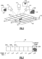
Figure 2 schematically illustrates apath 30 of relative movement between thesensor 14 and thecomponent 16. The computing device 12 is configured to move thesensor 14 along theexample path 30 relative to thecomponent 16 to record a plurality of sensor readings of thecomponent 16. In the example ofFigure 2 , a sensor reading is recorded for each of a plurality ofregions 32 of thecomponent 16. Thepath 30 may be a predefined path based on a computer model of thecomponent 16 that is stored in memory of the computing device 12, for example. - As will be discussed below in greater detail, the computing device 12 is configured to determine an appearance metric for a particular one of the sensor readings, and compare that metric to an aggregrate, nominal appearance metric for preceding ones of the sensors readings (and discussed below in greater detail). If a difference between the metrics exceeds a threshold, the computing device 12 determines that the particular sensor reading depicts an anomalous region, and records additional sensor readings of the anomalous region using one or more sensing parameters that differ from those used to record the anomalous sensor reading, in order to gain additional insight into the anomalous region. Each appearance metric represents a high-level statistical characterization of its associated depicted
region 32. - In
Figure 2 , region 32' is an anomalous region because it includes a darkenedarea 33 that is substantially darker than the neighboringregions 32. A first sensor reading 34A is shown corresponding to a first view of the anomalous region 32 (e.g., with a sensor angle ϑs of approximately 90°). If the sensor reading is a photographic image, the darkenedarea 33 is likely to cause certain appearance metrics, such as, in the example of a camera sensor, average sensor value (e.g., average pixel value), sensor value gradient (e.g., pixel value gradient), and/or edge detection / circle detection to differ from the preceding images (e.g., differ from a certain number of preceding images and/or differ from an average value of a certain number of preceding images). - In the example of a LIDAR sensor, the metric may indicate an intensity or distance traveled of a LIDAR return beam, for example. In the example of an ultrasonic sensor, the metric may indicate an intensity of a sound beam reflected from within a defect in the part for pulse echo ultrasonic, and/or an intensity of a sound beam emanating from another side of the part in a through transmission ultrasonic. A similar concept may apply for x-rays where the metric could include x-ray signal attenuation.
- Based on the difference between the metric and the nominal appearance metric (discussed above), the computing device 12 controls the
sensor 14 and/or the lighting device 18 to recordadditional sensor readings anomalous sensor reading 34A. The additional sensor readings may offer further insight or greater visibility of the potential defect and/or degradation through this variation of parameters. - The computing device 12 may be driven by information theoretic and/or curiosity-based principles in its exploration of a candidate region of interest to gain insight into a potential defect and/or degradation through the capture of dissimilar sensor readings based on the idea that dissimilar sensor readings of the same region likely offer different insights. These dissimilar sensor readings can be captured through varying sensing parameters such as viewing angle, zoom, and lighting conditions. By varying these parameters, more dissimilar images, each providing unique insight, can be obtained efficiently.
- In an example where the
sensor 14 is a camera, some non-limiting examples of differing sensing parameters (which in this example would be photographic parameters) that may be used for a particular sensor reading (in this example a particular image) as compared to a preceding sensor reading may include one or any combination of the following, for example: -
different camera 14 position relative to thecomponent 16, -
different camera 14 orientation relative to thecomponent 16, as indicated by the sensor angle ϑs , which in this example would be a camera angle, - different lighting device 18 location relative to the
component 16, - different lighting device 18 orientation relative to the
component 16, as indicated by the lighting angle ϑL , - different lighting source 18 brightness, and/or
- different image resolution.
- As discussed above, a camera is a non-limiting example, and other sensors could be used such as a depth sensor (e.g., LIDAR or stereovision), an ultrasonic sensor, and/or an x-ray imaging device, for example. Some sensing parameters that may be used for a particular sensor reading (for cameras or non-camera sensors) could include any one or combination of the following, for example:
- a distance between the
sensor 14 and thecomponent 16, - the sensor angle ϑs with respect to the
component 16, and/or - a position of the
sensor 14 with respect to thecomponent 16. -
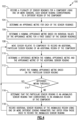
Figure 3 schematically illustrates movement of thesensor 14 relative to thecomponent 16. A plurality of neighboringregions 32 are shown, each of which are recorded in a separate sensor reading. Thus, a first sensor reading ofregion 32A is recorded at time t=1, a second sensor reading ofregion 32B is recorded at time t=2, a third sensor reading ofregion 32C is recorded at time t=3, and so on, until a sensor reading ofregion 32N is recorded at time t=N. In one example, the nominal appearance metric is calculated based on the sensor readings of the M neighboring regions that precederegion 32N and/or the M most recent sensor readings. - If a short-term memory window used for the preceding M images to determine the nominal appearance metric is relatively small, the nominal appearance metric is likely to be contextually appropriate, and to support anomaly detection that is adaptive and robust to changes in part surface characteristics, defect type, and environmental conditions.
- The window M may be adjusted based on a number of factors. For example, if the component features a repetitive surface pattern, the computing device 12 may be configured so that the window includes an entire unit of the pattern, so that the pattern itself is not interpreted as an anomaly. The window may also be adjusted adaptively by using change detection techniques, e.g., looking at the trends of how the metric is statistically changing over the window and identifying a point where there is large enough change which determines the end point of the window.
-
Figure 4 is a flowchart of anexample method 100 of inspecting acomponent 16 for anomalous regions. A plurality of sensor readings (e.g., images 34) of thecomponent 16 are recorded using one or more sensors 14 (step 102), with each sensor reading corresponding to adifferent region 32 of thecomponent 16. An appearance metric is determined for each of the sensor readings (step 104). The appearance metric may be an average sensor value (e.g., pixel value), a sensor value gradient (e.g., pixel value gradient), or various low-level detected features such as edges, corners, and/or circles, for example. In one example, where thesensor 14 is a depth sensor, the sensor data may be voxelized and characterized through determination of number of surfaces, centroids, etc. - A nominal appearance metric is determined based on individual values of the appearance metric for a first subset of the sensor readings (step 106) (e.g., the M preceding sensor readings as discussed in connection with
Figure 3 ). The nominal appearance metric may be an average of the individual values, for example. The appearance metric may be defined by a human expert, or may be learned automatically using deep learning methods, for example. - The
sensor 14 is moved relative to thecomponent 16 to record an additional, particular sensor reading of an additional region 32 (step 108). Moving thesensor 14 relative to thecomponent 16 may include using the set of one or morerobotic arms 20, for example. Alternatively, if thecamera 14 is a part of a snake-arm robot or secured to a drone, then the snake-arm robot or drone could be used to provide the movement of thecamera 14 relative to thecomponent 16. - A difference is determined between the nominal appearance metric and the appearance metric of the particular sensor reading 34 (step 110). The nominal appearance metric is updated based on the particular sensor reading (step 112). In one example, the updating of
step 112 includes recalculating the nominal appearance metric based only on the preceding M sensor readings, so that sensor readings before the earliest of the M sensor readings are excluded from the updated determination of the nominal appearance metric. - The difference determined in
step 110 is compared to a threshold (step 114). If the difference is within the threshold (a "yes" to step 114), the method proceeds back to step 108 for another iteration. The threshold may be fixed or adaptive. In one example that utilizes an adaptive threshold for comparison instep 114, the threshold is lowered based on an anomalous area detection rate being below a first detection threshold (e.g., corresponding to a first detection rate, below which false negative detections may be likely) and/or is raised based on an anomalous detection rate being above a second detection threshold (e.g., corresponding to a second detection rate, above which false positive detections may be likely). - If the difference exceeds the threshold (a "no" to step 114), a determination is made that the particular sensor reading is an anomalous sensor reading that corresponds to an anomalous region of the component (step 116), and additional sensor readings of the anomalous region are recorded using one or more sensing parameters that differ from those used to record the anomalous sensor reading (step 118). Steps 108-118 are then iteratively repeated to continue inspecting the
component 16. - In one example, the quantity of additional sensor readings that are recorded in
step 118 depends on a magnitude of the difference determined instep 112. In one example, as the difference increases, the quantity of additional sensor readings also increases. In another example, as the different increases, the quantity of additional sensor readings decreases. Thus, the magnitude of the difference determined instep 112 may be used to control the exploration strategy of thecomponent 16. - In one example, a second sensor that is different from the
first sensor 14 is used to record the additional sensor readings (e.g., additional images) of the anomalous area instep 118 while thefirst sensor 14 continues to traverse the path and record sensor readings ofregions 32 of thecomponent 16 that have not yet been assessed for whether they are anomalous. Thus, thesystem 10 may be a multi-agent system, where afirst sensor 14 identifies anomalous regions, and asecond sensor 14 explores them. As used above, the sensors being "different" from each other may mean that they are separate, but are a same type of sensor (e.g., both cameras), or are separate and are also different types of sensors (e.g., one is a camera, and one is a LIDAR sensor, ultrasonic sensor, or x-ray imaging device, for example). In one example, thesensors 14 each explore thecomponent 16 independently and explore the anomalous regions they respectively identify. - In one example, in conjunction with
step 118, based on detection of an anomalous region, the computing device 12 assesses the sensor readings to determine what type of anomaly is depicted. This may include one or any combination of the following, for example: comparison against template / reference images, analyzing detected features, such as edges, and/or utilizing a neural network (e.g., that has been trained with historical sensor readings for anomalies and/or specific types of defects). - The
method 100 provides for a generalized determination of anomalous regions to support defect detection and identification that is robust to variation in lighting conditions, part surface characteristics, or defect appearance that would limit the usefulness of predefined models or libraries of features for defect detection. Through a high-level statistical characterization of a currently-viewed region, and comparison of this characterization with a short-term memory window including the average characterization of some number of neighboring, previously-viewed regions, a determination can be made as to whether the currently-viewed region is anomalous. - The short-term memory window may be frequently updated, ensuring that the nominal appearance metric is contextually-appropriate. This supports anomaly detection that is adaptive and robust to changes in part surface characteristics, defect type, and environmental conditions.
- The
method 100 provides for an enhanced, robot-enabled automated visual inspection through exploratory selective capture of additional sensor readings of anomalous, and potentially defect-containing, regions. Because anomalous regions may be identified based on sensor readings (e.g., images) of neighboring regions, differences between similar sensor readings can be used to identify anomalous regions, instead of relying on rigid definitions of potential defects, which may be limited to a relatively small amount of defect types and/or which may rely on sensor readings that were recorded under photographic and/or environmental conditions that differ from thesystem 10. For example, an image of a damaged turbine blade in a bright laboratory setting may look substantially different from an image of the same damaged component taken with a snake-arm robot inserted into a gas turbine engine. Thus, a highly-controlled sensing (e.g., photographic) environment is not required to get good results from themethod 100. - The
method 100 enables the selective deployment of additional sensing/processing resources, focusing their use in regions that have been identified as anomalous and, as such, more likely to contain a defect. This allows for generalized, efficient, and enhanced data collection to support automated inspection processes through the targeted use of sensing resources that would be very costly in time, memory, and computational resources if applied indiscriminately in a blanket manner (e.g., requiring multiple camera angles and multiple lighting angles for every region of a component, including non-anomalous regions). Using themethod 100, any anomaly can be flagged for selective, enhanced inspection, offering versatility and efficiency over approaches relying on a fixed set of defect classes or blanket use of resources. Themethod 100 is agile, robust, and rapidly re-deployable, and in a manner that improves confidence in defect detection. - Although example embodiments have been disclosed, a worker of ordinary skill in this art would recognize that certain modifications would come within the scope of this disclosure. For that reason, the following claims should be studied to determine the scope and content of this disclosure.
Claims (14)
- A method of inspecting a component (16) for anomalous regions (32'), comprising:recording a plurality of sensor readings (34A) for a component (16) using one or more sensors (14; 14A; 14B; 14C), each sensor reading (34A) corresponding to a different region (32; 32') of the component (16);determining an appearance metric for each of the sensor readings (34A);determining a nominal appearance metric based on individual values of the appearance metric for a first subset of the sensor readings (34A); andfor a particular sensor reading (34A) of the plurality of sensor readings (34A) that is outside of the first subset:determining a difference between the nominal appearance metric and the appearance metric of the particular sensor reading (34A);updating the nominal appearance metric based on the particular sensor reading (34A); andbased on the difference exceeding a threshold, determining that the particular sensor reading (34A) is an anomalous sensor reading (34A) that corresponds to an anomalous region (32') of the component (16), and recording additional sensor readings (34B; 34C) of the anomalous region (32') using one or more different sensing parameters that differ from those used to record the anomalous sensor reading (34A).
- The method of claim 1, wherein the one or more sensors (14; 14A; 14B; 14C) include a first sensor (14; 14A; 14B; 14C) and a second sensor (14; 14A; 14B; 14C), said recording a plurality of sensor readings (34A) is performed using the first sensor (14; 14A; 14B; 14C), and the method comprises:moving the first sensor (14; 14A; 14B; 14C) relative to the component (16) along a path (30) to position the first sensor (14; 14A; 14B; 14C) for said recording a plurality of sensor readings (34A); andusing a second sensor (14; 14A; 14B; 14C), which is separate from the first sensor (14; 14A; 14B; 14C), for said recording additional sensor readings (34B; 34C) while the first sensor (14; 14A; 14B; 14C) continues to follow the path (30).
- The method of claim 2, wherein said moving the first sensor (14; 14A; 14B; 14C) relative to the component (16) comprises using a set of one or more robotic arms (20), a snake-arm robot (27), or a drone (25) to move the first sensor (14; 14A; 14B; 14C) relative to the component.
- The method of any preceding claim, wherein said updating the nominal appearance metric comprises calculating the nominal appearance metric based on the appearance metric of the particular sensor reading (34A) and M most recent sensor readings that precede the particular sensor reading (34A).
- A system (10) for inspecting a component (16) for anomalous regions (32'), comprising:one or more sensors (14; 14A; 14B; 14C); andprocessing circuitry configured to:record a plurality of sensor readings (34A) for a component (16) using the one or more sensors (14; 14A; 14B; 14C), each sensor reading (34A) corresponding to a different region (32; 32') of the component (16);determine an appearance metric for each of the sensor readings (34A);determine a nominal appearance metric based on individual values of the appearance metric for a first subset of the sensor readings (34A); andfor a particular sensor reading (34A) of the plurality of sensor readings (34A) that is outside of the first subset:determine a difference between the nominal appearance metric and the appearance metric of the particular sensor reading (34A);update the nominal appearance metric based on the particular sensor reading (34A); andbased on the difference exceeding a threshold, determine that the particular sensor reading (34A) is an anomalous sensor reading (34A) that corresponds to an anomalous region (32') of the component (16), and record additional sensor readings (34B; 34C) of the anomalous region (32') using one or more different sensing parameters that differ from those used to record the anomalous sensor reading (34A).
- The system of claim 5 or method of any of claims 1 to 4 wherein the one or more sensors (14; 14A; 14B; 14C) include a camera.
- The system of claim 5 or 6 or method of any of claims 1 to 4 or 6, wherein the one or more different sensing parameters include an imaging resolution of the at least one sensor (14; 14A; 14B; 14C).
- The system of any of claims 5 to 7, wherein the one or more sensors (14; 14A; 14B; 14C) include a first sensor (14; 14A; 14B; 14C) and a second sensor (14; 14A; 14B; 14C), and the processing circuitry is configured to:use the first sensor (14; 14A; 14B; 14C) to record the plurality of sensor readings (34A), and move the first sensor (14; 14A; 14B; 14C) relative to the component (16) along a path (30) to position the first sensor (14; 14A; 14B; 14C) to record the plurality of sensor readings (34A);wherein the second sensor (14; 14A; 14B; 14C), which is separate from the first sensor (14; 14A; 14B; 14C), is used to record the additional sensor readings (34B; 34C) while the first sensor (14; 14A; 14B; 14C ) continues to follow the path (30).
- The system of claim 8 or method of claim 2 or any of claims 3, 4, 6 or 7 as dependent on claim 2, wherein the first and second sensors (14; 14A; 14B; 14C) are both cameras.
- The system of claim 8 or method of claim 2 or any of claims 3, 4, 6 or 7 as dependent on claim 2, wherein one of the first and second sensors (14; 14A; 14B; 14C) is a camera, and the other of the first and second sensors (14; 14A; 14B; 14C) is a depth sensor, an ultrasonic sensor, or an x-ray imaging device.
- The system of any of claims 8 to 10, including:a set of one or more robotic arms (20), a snake-arm robot (27), or a drone (25);wherein the processing circuitry is configured to use said set of one or more robotic arms (20), said snake-arm robot (27), or said drone (25) to move the first sensor (14; 14A; 14B; 14C) relative to the component (16).
- The system or method of any preceding claim, wherein the one or more different sensing parameters include one or more of:a position of the sensor (14; 14A; 14B; 14C) relative to the component (16);a distance between the sensor (14; 14A; 14B; 14C) and the component (16); oran angle (Θs) of the sensor (14; 14A; 14B; 14C) relative to the component (16).
- The system or method of any preceding claim, wherein the one or more different sensing parameters includes one or more of: a position of a light source (18) relative to the component (16), an orientation of the light source (18) relative to the component (16), or a brightness of the light source (18).
- The system of any of claims 5 to 13, wherein to update the nominal appearance metric, the processing circuitry is configured to calculate the nominal appearance metric based on the appearance metric of the particular sensor reading (34A) and M most recent sensor readings that precede the particular sensor reading (34A).
Applications Claiming Priority (1)
| Application Number | Priority Date | Filing Date | Title |
|---|---|---|---|
| US17/744,223 US12163970B2 (en) | 2022-05-13 | 2022-05-13 | System and method for inspecting a component for anomalous regions |
Publications (2)
| Publication Number | Publication Date |
|---|---|
| EP4276747A1 true EP4276747A1 (en) | 2023-11-15 |
| EP4276747B1 EP4276747B1 (en) | 2025-12-24 |
Family
ID=86329129
Family Applications (1)
| Application Number | Title | Priority Date | Filing Date |
|---|---|---|---|
| EP23171695.2A Active EP4276747B1 (en) | 2022-05-13 | 2023-05-04 | System and method for inspecting a component for anomalous region |
Country Status (2)
| Country | Link |
|---|---|
| US (1) | US12163970B2 (en) |
| EP (1) | EP4276747B1 (en) |
Cited By (1)
| Publication number | Priority date | Publication date | Assignee | Title |
|---|---|---|---|---|
| EP4571298A1 (en) * | 2023-12-11 | 2025-06-18 | Rolls-Royce plc | Imaging |
Citations (2)
| Publication number | Priority date | Publication date | Assignee | Title |
|---|---|---|---|---|
| US20190285980A1 (en) * | 2018-03-19 | 2019-09-19 | Toshiba Memory Corporation | Defect inspection device and defect inspection method |
| WO2019177539A1 (en) * | 2018-03-14 | 2019-09-19 | Agency For Science, Technology And Research | Method for visual inspection and apparatus thereof |
Family Cites Families (7)
| Publication number | Priority date | Publication date | Assignee | Title |
|---|---|---|---|---|
| US8223327B2 (en) | 2009-01-26 | 2012-07-17 | Kla-Tencor Corp. | Systems and methods for detecting defects on a wafer |
| CN105122046B (en) | 2013-03-29 | 2018-01-23 | 斯奈克玛 | Methods for detecting defects on objects |
| US9816939B2 (en) | 2014-07-22 | 2017-11-14 | Kla-Tencor Corp. | Virtual inspection systems with multiple modes |
| US10393671B2 (en) | 2015-04-29 | 2019-08-27 | Kla-Tencor Corp. | Intra-die defect detection |
| CN106780455B (en) | 2016-12-07 | 2019-11-19 | 五邑大学 | A Product Surface Detection Method Based on Sliding Local Neighborhood Window |
| US10861148B2 (en) * | 2018-04-30 | 2020-12-08 | General Electric Company | Systems and methods for improved component inspection |
| CN110211112A (en) | 2019-05-31 | 2019-09-06 | 华中科技大学 | A kind of casting defect inspection method based on filtering selective search |
-
2022
- 2022-05-13 US US17/744,223 patent/US12163970B2/en active Active
-
2023
- 2023-05-04 EP EP23171695.2A patent/EP4276747B1/en active Active
Patent Citations (2)
| Publication number | Priority date | Publication date | Assignee | Title |
|---|---|---|---|---|
| WO2019177539A1 (en) * | 2018-03-14 | 2019-09-19 | Agency For Science, Technology And Research | Method for visual inspection and apparatus thereof |
| US20190285980A1 (en) * | 2018-03-19 | 2019-09-19 | Toshiba Memory Corporation | Defect inspection device and defect inspection method |
Non-Patent Citations (1)
| Title |
|---|
| BLAKESLEE BRIGID A ET AL: "Selective and Hierarchical Allocation of Sensing Resources for Anomalous Target Identification in Exploratory Missions", 2021 IEEE INTERNATIONAL SYMPOSIUM ON SAFETY, SECURITY, AND RESCUE ROBOTICS (SSRR), IEEE, 25 October 2021 (2021-10-25), pages 196 - 203, XP034021438, DOI: 10.1109/SSRR53300.2021.9597688 * |
Cited By (1)
| Publication number | Priority date | Publication date | Assignee | Title |
|---|---|---|---|---|
| EP4571298A1 (en) * | 2023-12-11 | 2025-06-18 | Rolls-Royce plc | Imaging |
Also Published As
| Publication number | Publication date |
|---|---|
| US20230366896A1 (en) | 2023-11-16 |
| EP4276747B1 (en) | 2025-12-24 |
| US12163970B2 (en) | 2024-12-10 |
Similar Documents
| Publication | Publication Date | Title |
|---|---|---|
| US12556662B2 (en) | Object inspection system and method for inspecting an object | |
| CN108291880B (en) | Arrangement, method, device and software for checking containers | |
| CN111627072A (en) | Method and device for calibrating multiple sensors and storage medium | |
| CN113822844A (en) | Defect detection method, device and storage medium for unmanned aerial vehicle inspection of wind turbine blades | |
| US7599050B2 (en) | Surface defect inspecting method and device | |
| US11931910B2 (en) | Use of artificial intelligence models to identify fasteners and perform related operations | |
| CN113369761A (en) | Method and system for guiding robot welding seam positioning based on vision | |
| EP4276747B1 (en) | System and method for inspecting a component for anomalous region | |
| CN117522830A (en) | Point cloud scanning system for detecting boiler corrosion | |
| WO2024181994A1 (en) | Robotic visual tactile surface inspection system | |
| CN116088130A (en) | Line laser focusing method and device, optical equipment and storage medium | |
| CN117745678A (en) | Conveyer belt roller encapsulation detection method, conveyer belt roller encapsulation detection device, conveyer belt roller encapsulation detection equipment and storage medium | |
| US20240404041A1 (en) | Systems and methods for onboard auto-inspection of vehicles using reflective surfaces | |
| CN115229374B (en) | Method and device for detecting quality of automobile body-in-white weld seam based on deep learning | |
| US10861148B2 (en) | Systems and methods for improved component inspection | |
| JP7469740B2 (en) | Belt inspection system and belt inspection program | |
| Moravec et al. | Robust maximum-likelihood on-line LiDAR-to-camera calibration monitoring and refinement | |
| EP4718374A1 (en) | Detection of sheet anomalies for laser machine | |
| CN121661613B (en) | Unmanned vehicle and robot dog collaborative inspection system and method based on confidence | |
| KR102905991B1 (en) | Appearance inspection device and method | |
| CN120651879B (en) | Pipeline X-ray flaw detection method and system based on multi-view self-adaption | |
| CN111767895A (en) | Device identification method, device, robot and computer-readable storage medium | |
| CN119821980B (en) | Plow type belt discharger position state monitoring method and device based on machine vision | |
| AU2021103287A4 (en) | Computer implemented method for scanning for determining characteristics of materials using artificial intelligence | |
| US20260056131A1 (en) | Optical laser systems and methods for determining contamination |
Legal Events
| Date | Code | Title | Description |
|---|---|---|---|
| PUAI | Public reference made under article 153(3) epc to a published international application that has entered the european phase |
Free format text: ORIGINAL CODE: 0009012 |
|
| STAA | Information on the status of an ep patent application or granted ep patent |
Free format text: STATUS: THE APPLICATION HAS BEEN PUBLISHED |
|
| AK | Designated contracting states |
Kind code of ref document: A1 Designated state(s): AL AT BE BG CH CY CZ DE DK EE ES FI FR GB GR HR HU IE IS IT LI LT LU LV MC ME MK MT NL NO PL PT RO RS SE SI SK SM TR |
|
| STAA | Information on the status of an ep patent application or granted ep patent |
Free format text: STATUS: REQUEST FOR EXAMINATION WAS MADE |
|
| 17P | Request for examination filed |
Effective date: 20240510 |
|
| RBV | Designated contracting states (corrected) |
Designated state(s): AL AT BE BG CH CY CZ DE DK EE ES FI FR GB GR HR HU IE IS IT LI LT LU LV MC ME MK MT NL NO PL PT RO RS SE SI SK SM TR |
|
| GRAP | Despatch of communication of intention to grant a patent |
Free format text: ORIGINAL CODE: EPIDOSNIGR1 |
|
| STAA | Information on the status of an ep patent application or granted ep patent |
Free format text: STATUS: GRANT OF PATENT IS INTENDED |
|
| RIC1 | Information provided on ipc code assigned before grant |
Ipc: G06T 7/00 20170101AFI20250730BHEP Ipc: G05B 23/02 20060101ALI20250730BHEP |
|
| INTG | Intention to grant announced |
Effective date: 20250818 |
|
| GRAS | Grant fee paid |
Free format text: ORIGINAL CODE: EPIDOSNIGR3 |
|
| GRAA | (expected) grant |
Free format text: ORIGINAL CODE: 0009210 |
|
| STAA | Information on the status of an ep patent application or granted ep patent |
Free format text: STATUS: THE PATENT HAS BEEN GRANTED |
|
| AK | Designated contracting states |
Kind code of ref document: B1 Designated state(s): AL AT BE BG CH CY CZ DE DK EE ES FI FR GB GR HR HU IE IS IT LI LT LU LV MC ME MK MT NL NO PL PT RO RS SE SI SK SM TR |
|
| REG | Reference to a national code |
Ref country code: CH Ref legal event code: F10 Free format text: ST27 STATUS EVENT CODE: U-0-0-F10-F00 (AS PROVIDED BY THE NATIONAL OFFICE) Effective date: 20251224 Ref country code: GB Ref legal event code: FG4D |
|
| REG | Reference to a national code |
Ref country code: DE Ref legal event code: R096 Ref document number: 602023009981 Country of ref document: DE |
|
| REG | Reference to a national code |
Ref country code: LT Ref legal event code: MG9D |
|
| PG25 | Lapsed in a contracting state [announced via postgrant information from national office to epo] |
Ref country code: NO Free format text: LAPSE BECAUSE OF FAILURE TO SUBMIT A TRANSLATION OF THE DESCRIPTION OR TO PAY THE FEE WITHIN THE PRESCRIBED TIME-LIMIT Effective date: 20260324 |
|
| PG25 | Lapsed in a contracting state [announced via postgrant information from national office to epo] |
Ref country code: FI Free format text: LAPSE BECAUSE OF FAILURE TO SUBMIT A TRANSLATION OF THE DESCRIPTION OR TO PAY THE FEE WITHIN THE PRESCRIBED TIME-LIMIT Effective date: 20251224 Ref country code: HR Free format text: LAPSE BECAUSE OF FAILURE TO SUBMIT A TRANSLATION OF THE DESCRIPTION OR TO PAY THE FEE WITHIN THE PRESCRIBED TIME-LIMIT Effective date: 20251224 |
|
| PG25 | Lapsed in a contracting state [announced via postgrant information from national office to epo] |
Ref country code: RS Free format text: LAPSE BECAUSE OF FAILURE TO SUBMIT A TRANSLATION OF THE DESCRIPTION OR TO PAY THE FEE WITHIN THE PRESCRIBED TIME-LIMIT Effective date: 20260324 |
|
| PG25 | Lapsed in a contracting state [announced via postgrant information from national office to epo] |
Ref country code: LV Free format text: LAPSE BECAUSE OF FAILURE TO SUBMIT A TRANSLATION OF THE DESCRIPTION OR TO PAY THE FEE WITHIN THE PRESCRIBED TIME-LIMIT Effective date: 20251224 |
|
| REG | Reference to a national code |
Ref country code: NL Ref legal event code: MP Effective date: 20251224 |
|
| PG25 | Lapsed in a contracting state [announced via postgrant information from national office to epo] |
Ref country code: BG Free format text: LAPSE BECAUSE OF FAILURE TO SUBMIT A TRANSLATION OF THE DESCRIPTION OR TO PAY THE FEE WITHIN THE PRESCRIBED TIME-LIMIT Effective date: 20251224 |