EP4276574A1 - Linkage device, apparatus accessory and electronic apparatus - Google Patents
Linkage device, apparatus accessory and electronic apparatus Download PDFInfo
- Publication number
- EP4276574A1 EP4276574A1 EP22192632.2A EP22192632A EP4276574A1 EP 4276574 A1 EP4276574 A1 EP 4276574A1 EP 22192632 A EP22192632 A EP 22192632A EP 4276574 A1 EP4276574 A1 EP 4276574A1
- Authority
- EP
- European Patent Office
- Prior art keywords
- shaft
- during
- stroke
- linkage device
- stopping
- Prior art date
- Legal status (The legal status is an assumption and is not a legal conclusion. Google has not performed a legal analysis and makes no representation as to the accuracy of the status listed.)
- Granted
Links
Images



Classifications
-
- F—MECHANICAL ENGINEERING; LIGHTING; HEATING; WEAPONS; BLASTING
- F16—ENGINEERING ELEMENTS AND UNITS; GENERAL MEASURES FOR PRODUCING AND MAINTAINING EFFECTIVE FUNCTIONING OF MACHINES OR INSTALLATIONS; THERMAL INSULATION IN GENERAL
- F16M—FRAMES, CASINGS OR BEDS OF ENGINES, MACHINES OR APPARATUS, NOT SPECIFIC TO ENGINES, MACHINES OR APPARATUS PROVIDED FOR ELSEWHERE; STANDS; SUPPORTS
- F16M13/00—Other supports for positioning apparatus or articles; Means for steadying hand-held apparatus or articles
- F16M13/005—Other supports for positioning apparatus or articles; Means for steadying hand-held apparatus or articles integral with the apparatus or articles to be supported
-
- G—PHYSICS
- G06—COMPUTING OR CALCULATING; COUNTING
- G06F—ELECTRIC DIGITAL DATA PROCESSING
- G06F1/00—Details not covered by groups G06F3/00 - G06F13/00 and G06F21/00
- G06F1/16—Constructional details or arrangements
- G06F1/1613—Constructional details or arrangements for portable computers
- G06F1/1633—Constructional details or arrangements of portable computers not specific to the type of enclosures covered by groups G06F1/1615 - G06F1/1626
- G06F1/1675—Miscellaneous details related to the relative movement between the different enclosures or enclosure parts
- G06F1/1681—Details related solely to hinges
-
- F—MECHANICAL ENGINEERING; LIGHTING; HEATING; WEAPONS; BLASTING
- F16—ENGINEERING ELEMENTS AND UNITS; GENERAL MEASURES FOR PRODUCING AND MAINTAINING EFFECTIVE FUNCTIONING OF MACHINES OR INSTALLATIONS; THERMAL INSULATION IN GENERAL
- F16C—SHAFTS; FLEXIBLE SHAFTS; ELEMENTS OR CRANKSHAFT MECHANISMS; ROTARY BODIES OTHER THAN GEARING ELEMENTS; BEARINGS
- F16C11/00—Pivots; Pivotal connections
- F16C11/04—Pivotal connections
-
- F—MECHANICAL ENGINEERING; LIGHTING; HEATING; WEAPONS; BLASTING
- F16—ENGINEERING ELEMENTS AND UNITS; GENERAL MEASURES FOR PRODUCING AND MAINTAINING EFFECTIVE FUNCTIONING OF MACHINES OR INSTALLATIONS; THERMAL INSULATION IN GENERAL
- F16C—SHAFTS; FLEXIBLE SHAFTS; ELEMENTS OR CRANKSHAFT MECHANISMS; ROTARY BODIES OTHER THAN GEARING ELEMENTS; BEARINGS
- F16C11/00—Pivots; Pivotal connections
- F16C11/04—Pivotal connections
- F16C11/06—Ball-joints; Other joints having more than one degree of angular freedom, i.e. universal joints
-
- F—MECHANICAL ENGINEERING; LIGHTING; HEATING; WEAPONS; BLASTING
- F16—ENGINEERING ELEMENTS AND UNITS; GENERAL MEASURES FOR PRODUCING AND MAINTAINING EFFECTIVE FUNCTIONING OF MACHINES OR INSTALLATIONS; THERMAL INSULATION IN GENERAL
- F16C—SHAFTS; FLEXIBLE SHAFTS; ELEMENTS OR CRANKSHAFT MECHANISMS; ROTARY BODIES OTHER THAN GEARING ELEMENTS; BEARINGS
- F16C11/00—Pivots; Pivotal connections
- F16C11/04—Pivotal connections
- F16C11/10—Arrangements for locking
- F16C11/103—Arrangements for locking frictionally clamped
-
- F—MECHANICAL ENGINEERING; LIGHTING; HEATING; WEAPONS; BLASTING
- F16—ENGINEERING ELEMENTS AND UNITS; GENERAL MEASURES FOR PRODUCING AND MAINTAINING EFFECTIVE FUNCTIONING OF MACHINES OR INSTALLATIONS; THERMAL INSULATION IN GENERAL
- F16C—SHAFTS; FLEXIBLE SHAFTS; ELEMENTS OR CRANKSHAFT MECHANISMS; ROTARY BODIES OTHER THAN GEARING ELEMENTS; BEARINGS
- F16C11/00—Pivots; Pivotal connections
- F16C11/04—Pivotal connections
- F16C11/12—Pivotal connections incorporating flexible connections, e.g. leaf springs
-
- F—MECHANICAL ENGINEERING; LIGHTING; HEATING; WEAPONS; BLASTING
- F16—ENGINEERING ELEMENTS AND UNITS; GENERAL MEASURES FOR PRODUCING AND MAINTAINING EFFECTIVE FUNCTIONING OF MACHINES OR INSTALLATIONS; THERMAL INSULATION IN GENERAL
- F16D—COUPLINGS FOR TRANSMITTING ROTATION; CLUTCHES; BRAKES
- F16D3/00—Yielding couplings, i.e. with means permitting movement between the connected parts during the drive
- F16D3/16—Universal joints in which flexibility is produced by means of pivots or sliding or rolling connecting parts
- F16D3/26—Hooke's joints or other joints with an equivalent intermediate member to which each coupling part is pivotally or slidably connected
-
- G—PHYSICS
- G06—COMPUTING OR CALCULATING; COUNTING
- G06F—ELECTRIC DIGITAL DATA PROCESSING
- G06F1/00—Details not covered by groups G06F3/00 - G06F13/00 and G06F21/00
- G06F1/16—Constructional details or arrangements
- G06F1/1613—Constructional details or arrangements for portable computers
- G06F1/1615—Constructional details or arrangements for portable computers with several enclosures having relative motions, each enclosure supporting at least one I/O or computing function
- G06F1/1616—Constructional details or arrangements for portable computers with several enclosures having relative motions, each enclosure supporting at least one I/O or computing function with folding flat displays, e.g. laptop computers or notebooks having a clamshell configuration, with body parts pivoting to an open position around an axis parallel to the plane they define in closed position
-
- G—PHYSICS
- G06—COMPUTING OR CALCULATING; COUNTING
- G06F—ELECTRIC DIGITAL DATA PROCESSING
- G06F1/00—Details not covered by groups G06F3/00 - G06F13/00 and G06F21/00
- G06F1/16—Constructional details or arrangements
- G06F1/1613—Constructional details or arrangements for portable computers
- G06F1/1633—Constructional details or arrangements of portable computers not specific to the type of enclosures covered by groups G06F1/1615 - G06F1/1626
- G06F1/1675—Miscellaneous details related to the relative movement between the different enclosures or enclosure parts
-
- G—PHYSICS
- G06—COMPUTING OR CALCULATING; COUNTING
- G06F—ELECTRIC DIGITAL DATA PROCESSING
- G06F1/00—Details not covered by groups G06F3/00 - G06F13/00 and G06F21/00
- G06F1/16—Constructional details or arrangements
- G06F1/1613—Constructional details or arrangements for portable computers
- G06F1/1633—Constructional details or arrangements of portable computers not specific to the type of enclosures covered by groups G06F1/1615 - G06F1/1626
- G06F1/1675—Miscellaneous details related to the relative movement between the different enclosures or enclosure parts
- G06F1/1679—Miscellaneous details related to the relative movement between the different enclosures or enclosure parts for locking or maintaining the movable parts of the enclosure in a fixed position, e.g. latching mechanism at the edge of the display in a laptop or for the screen protective cover of a PDA
-
- H—ELECTRICITY
- H04—ELECTRIC COMMUNICATION TECHNIQUE
- H04M—TELEPHONIC COMMUNICATION
- H04M1/00—Substation equipment, e.g. for use by subscribers
- H04M1/02—Constructional features of telephone sets
- H04M1/0202—Portable telephone sets, e.g. cordless phones, mobile phones or bar type handsets
- H04M1/0206—Portable telephones comprising a plurality of mechanically joined movable body parts, e.g. hinged housings
- H04M1/0208—Portable telephones comprising a plurality of mechanically joined movable body parts, e.g. hinged housings characterized by the relative motions of the body parts
- H04M1/0214—Foldable telephones, i.e. with body parts pivoting to an open position around an axis parallel to the plane they define in closed position
- H04M1/0216—Foldable in one direction, i.e. using a one degree of freedom hinge
-
- F—MECHANICAL ENGINEERING; LIGHTING; HEATING; WEAPONS; BLASTING
- F16—ENGINEERING ELEMENTS AND UNITS; GENERAL MEASURES FOR PRODUCING AND MAINTAINING EFFECTIVE FUNCTIONING OF MACHINES OR INSTALLATIONS; THERMAL INSULATION IN GENERAL
- F16C—SHAFTS; FLEXIBLE SHAFTS; ELEMENTS OR CRANKSHAFT MECHANISMS; ROTARY BODIES OTHER THAN GEARING ELEMENTS; BEARINGS
- F16C2370/00—Apparatus relating to physics, e.g. instruments
-
- F—MECHANICAL ENGINEERING; LIGHTING; HEATING; WEAPONS; BLASTING
- F16—ENGINEERING ELEMENTS AND UNITS; GENERAL MEASURES FOR PRODUCING AND MAINTAINING EFFECTIVE FUNCTIONING OF MACHINES OR INSTALLATIONS; THERMAL INSULATION IN GENERAL
- F16C—SHAFTS; FLEXIBLE SHAFTS; ELEMENTS OR CRANKSHAFT MECHANISMS; ROTARY BODIES OTHER THAN GEARING ELEMENTS; BEARINGS
- F16C2380/00—Electrical apparatus
Definitions
- the present invention relates to a field of mechanical linkage technology, and more particularly, to a linkage device, an apparatus accessory, and an electronic apparatus.
- the present invention aims to solve at least one of the technical problems in the related art to a certain extent.
- embodiments of the present invention propose a linkage device that can enhance the support stability and avoid tipping back an electronic apparatus.
- Embodiments of the present invention further propose an apparatus accessory having the linkage device.
- Embodiments of the present invention further propose an electronic apparatus having the linkage device or the apparatus accessory.
- a linkage device includes a drive component and a support member.
- the drive component is rotatable during a transmission stroke and an idle stroke.
- the support member is coupled to the drive component.
- the drive component and the support member are configured to rotate synchronously during the transmission stroke. At least a part of the drive component idles with respect to the support member during the idle stroke.
- the support member has a retracted position and a support position that are switched by the transmission stroke.
- the support member in the retracted position is suitable for storage.
- the support member in the support position is suitable for stopping and limiting.
- the linkage device can enhance the support stability and avoids tipping back the electronic apparatus.
- the drive component includes a first shaft and a second shaft, the second shaft being coupled to the support member; during the transmission stroke, the first shaft, the second shaft and the support member are transmissively coupled and rotate synchronously; and during the idle stroke, the first shaft and the second shaft are transmissively separated and the first shaft idles.
- the linkage device further includes an overturning member coupled to the first shaft, in which the overturning member is configured to drive the first shaft to reciprocally rotate, and in the support position, the support member stops and limits the overturning member.
- the support member extends in a same direction as the second shaft in the retracted position, and the support member extends at an angle to the second shaft in the support position.
- the linkage device further includes a limiting assembly.
- the limiting assembly is configured to act between the first shaft and the second shaft. During the idle stroke, the limiting assembly is configured to cooperate with the second shaft to limit rotation of the second shaft.
- the limiting assembly includes a stopping member; during the transmission stroke, the first shaft and the second shaft are rotatable with respect to the stopping member; and during the idle stroke, the first shaft is rotatable with respect to the stopping member, and the stopping member is configured to cooperate with the second shaft to limit the rotation of the second shaft.
- the limiting assembly includes: a first cam on the first shaft and being rotatable synchronously with the first shaft, an outer peripheral wall of the first cam including a first peripheral wall and a guide slot; and a second cam on the second shaft and being rotatable synchronously with the second shaft, an outer peripheral wall of the second cam including a second peripheral wall and a snap slot.
- the stopping member is fitted between the guide slot and the second peripheral wall and is configured to slide along the guide slot; and during the idle stroke, the stopping member is fitted between the snap slot and the first peripheral wall.
- the stopping member is slidable between the first cam and the second cam; the stopping member is configured to slide into the guide slot by a push of the second peripheral wall during a switch from the idle stroke to the transmission stroke; and the stopping member is configured to slide into the snap slot by a push of the first peripheral wall during a switch from the transmission stroke to the idle stroke.
- the stopping member is rotatable; the stopping member is configured to roll and is fitted between the guide slot and the second peripheral wall during the transmission stroke; and the stopping member is configured to roll and is fitted between the snap slot and the first peripheral wall during the idle stroke.
- the linkage device includes a transmission assembly acting between the first shaft and the second shaft.
- the first shaft is transmissively coupled to the second shaft through the transmission assembly, and the first shaft and the second shaft rotate in a common direction; and during the idle stroke, the transmission assembly is transmissively separated to allow the first shaft to idle.
- the transmission assembly includes: an incomplete gear on the first shaft; a first gear on the second shaft; and a second gear transmissively meshing between the incomplete gear and the first gear.
- the incomplete gear is configured to transmissively mesh with the second gear with during the transmission stroke and to be disengaged from the second gear during the idle stroke.
- the second gear includes a first segment and a second segment in an axial direction; the incomplete gear transmissively meshes with the first segment; and the first gear transmissively meshes with the second segment.
- the linkage device includes a damping assembly.
- the damping assembly includes a fixed portion and a movable portion; the movable portion is on the first shaft and is rotatable along with the first shaft; and the fixed portion and the movable portion are fitted together to form a damper, and the first shaft is held in position after rotation.
- the fixed portion includes a first protrusion on an end face abutting against the fixed portion
- the movable portion includes a second protrusion on an end face abutting against the fixed portion; during the transmission stroke, the first protrusion is configured to be stopped by the second protrusion; and during the idle stroke, the first protrusion is configured to cross over the second protrusion, and the movable portion is elastically retractable to allow the first protrusion to get over the second protrusion.
- the movable portion includes: an elastic member fitted over the first shaft and fitted with the first shaft in a rotation-resistant manner; and an adjusting member on the first shaft with a position of the adjusting member being adjustable.
- the elastic member is sandwiched between the adjusting member and the fixed portion, and the adjusting member is configured to stop an end of the elastic member and adjust an elastic force of the elastic member.
- the fixed portion includes a first stopping portion
- the first shaft includes a second stopping portion, the first stopping portion being fitted with and stopped by the second stopping portion to limit a rotation stroke of the first shaft.
- the linkage device includes a housing.
- the housing has a first abutting surface
- the support member has a second abutting surface
- the first abutting surface abuts against the second abutting surface in both the retracted position and the support position.
- the second shaft is coupled to the support member by a universal joint;
- the universal joint includes a first joint and a second joint, the first joint being coupled to the second shaft and the second joint being coupled to the support member; an axial direction of the first joint is at a first angle to an axial direction of the second joint;
- the second joint is rotatably assembled with the housing; and the first abutting surface and the second abutting surface are at a second angle to the axial direction of the second joint.
- the linkage device includes a plurality of fixing members.
- the first shaft is rotatably fitted with at least part of the fixing members
- the second shaft is rotatably fitted with at least part of the fixing members
- the first shaft and the second shaft are assembled to the housing by the plurality of fixing members.
- An apparatus accessory according to an embodiment of the present invention includes the linkage device in the above embodiments.
- the apparatus accessory includes a protective casing.
- the protective casing includes a first portion and a second portion; the first portion is swingable with respect to the second portion, and the first portion is coupled to the overturning member; and the second portion is coupled to the housing.
- An electronic apparatus includes the linkage device in the above embodiments or the apparatus accessory described in the above embodiments.
- a linkage device 100 includes a drive component 20 and a support member 4.
- the drive component 20 has a transmission stroke and an idle stroke.
- the drive component 20 is rotatable, and during rotation, a rotation stroke of the drive component 20 is divided into the transmission stroke and the idle stroke.
- the drive component 20 can rotate reciprocally, i.e., the drive component 20 can rotate forward and reversely. During the forward rotation, the rotation stroke of the drive component 20 is divided into the transmission stroke and the idle stroke.
- the support member 4 is transmissively coupled to the drive component 20, and the drive component 20 and the support member 4 can rotate synchronously during the rotation of the drive component 20 during the transmission stroke. During the rotation of the drive component 20 during the idle stroke, at least a part of the drive component 20 idles with respect to the support member 4.
- the drive component 20 is divided into two component units, namely, a first component unit (i.e., a first shaft described later) and a second component unit (i.e., a second shaft described later).
- the first component unit can rotate alone relative to the support member 4 and the second component unit when the drive component 20 rotates during the idle stroke.
- the first component unit, the second component unit and the support member 4 can rotate synchronously when the drive component 20 rotates during the transmission stroke.
- the transmission between the drive component 20 and the support member 4 can be interrupted when the drive component 20 rotates during the idle stroke, in which case the drive component 20 as a whole can rotate relative to the support member 4.
- the support member 4 has a retracted position and a support position that are switched by the transmission stroke. That is, when the drive component 20 rotates during the transmission stroke, the support member 4 can rotate along with the drive component 20 and can be switched between the retracted position and the support position.
- the support member 4 is suitable for storage, facilitating the storage of the linkage device 100.
- the support member 4 is suitable for stopping and limiting. For example, the support member 4 can stop and limit a display screen of an electronic apparatus, avoiding the overturning of the electronic apparatus.
- the linkage device 100 has a rotatable connection effect as ordinary hinges, and achieves an effect of linkage between the drive component 20 and the support member 4. That is, the support member 4 can be switched to the support position when a rotation function of the hinge is realized. Consequently, the support member 4 can support some components (such as the display screen and tablets), avoiding tipping back the electronic apparatus and enhancing the support stability.
- the drive component 20 includes a first shaft 2 as the first component unit and a second shaft 3 as the second component unit, the second shaft 3 being coupled to the support member 4.
- the first shaft 2, the second shaft 3 and the support member 4 are transmissively coupled and can rotate synchronously; and during the idle stroke, the first shaft 2 and the second shaft 3 are transmissively separated to allow the first shaft 2 to idle.
- both the first shaft 2 and the second shaft 3 extend in a left-right direction, and the first shaft 2 and the second shaft 3 are substantially parallel to each other.
- the first shaft 2 is rotatable in a direction M in Fig. 1 , and during the rotation of the first shaft 2, a rotation stroke of the first shaft 2 is divided into two stages, namely, a transmission stroke and an idle stroke.
- the first shaft 2 and the second shaft 3 are transmissively coupled and can rotate synchronously, in which case the support member 4 also rotates synchronously with the second shaft 3.
- the first shaft 2 and the second shaft 3 are transmissively separated, in which case the first shaft 2 can continue to rotate, while the second shaft 3 and the support member 4 remain stationary.
- the rotation stroke of the first shaft 2 can be divided into the transmission stroke and the idle stroke in each case.
- the linkage device 100 includes an overturning member 1 coupled to the first shaft 2; the overturning member 1 is configured to drive the first shaft 2 to reciprocally rotate; and in the support position, the support member 4 stops and limits the overturning member 1.
- the overturning member 1 is coupled to a left end of the first shaft 2, and the overturning member 1 cooperates with the first shaft 2 in a rotation-resistant manner.
- the first shaft 2 can be driven to rotate forward in the direction M or can be driven to rotate reversely in a direction opposite to the direction M.
- the overturning member 1 can be coupled to the display screen of the electronic apparatus, or the overturning member 1 can be integrated with the display screen and considered as a part of the display screen, so that a restraining effect can be achieved by stopping and limiting the overturning member 1 through the support member 4, and the support stability can be ensured.
- the support member 4 in the retracted position, extends in a same direction as the second shaft 3, and in the support position, the support member 4 extends at an angle to the second shaft 3.
- the support member 4 is coupled to the second shaft 3 and can rotate synchronously with the second shaft 3.
- the support member 4 is coupled to a right side of the second shaft 3 and the support member 4 has the retracted position and the support position during rotation.
- the support member 4 in the retracted position, the support member 4 extends in the same direction as the second shaft 3, i.e., the support member 4 also switches to a position extending generally along the left-right direction.
- the support member 4 and the second shaft 3 are at an angle, and the support member 4 is fitted with and stops the overturning member 1. That is, the support member 4 can be supported obliquely on the ground or on the table, and a bottom edge of the overturning member 1 can lap over the support member 4, preventing the overturning member 1 from being suspended after overturning.
- the overturning member 1 is coupled to the display screen and other components of the electronic apparatus, so that the overturning member 1 can be supported by the support member 4 after the overturning member 1 has been overturn, enhancing the support stability and avoiding tipping back the electronic apparatus.
- the overturning member 1 drives the support member 4 to rotate to the support position through the transmission of the first shaft 2 and the second shaft 3, then the support member 4 remains in the support position, and the overturning member 1 continues to rotate during the idle stroke, which can satisfy a requirement of opening and closing the overturning member 1 at a large angle, enrich the angle adjustment of the overturning member 1 and help to enhance the use convenience.
- the linkage device 100 includes a limiting assembly 6 that acts between the first shaft 2 and the second shaft 3. During the idle stroke, the limiting assembly 6 cooperates with the second shaft 3 to limit the rotation of the second shaft 3. Since the first shaft 2 and the second shaft 3 are transmissively separated during the idle stroke, the second shaft 3 is not restrained by any external force and when the support member 4 is subjected to a force, the second shaft 3 and the support member 4 easily rotate reversely, failing to realize a support effect.
- the limiting assembly 6 can restrain the second shaft 3 when the second shaft 3 loses the restraint from the first shaft 2. As a result, a situation where the second shaft 3 rotates at will can be avoided, and the support member 4 can realize the support effect; moreover, the first shaft 2 can rotate independently of the second shaft 3, satisfying the large-angle opening and closing requirement.
- the limiting assembly includes a stopping member 61.
- the first shaft 2 and the second shaft 3 are rotatable with respect to the stopping member 61.
- the first shaft 2 is rotatable with respect to the stopping member 61, and the stopping member 61 cooperates with the second shaft 3 to limit the rotation of the second shaft 3.
- the stopping member 61 plays a stopping role only during the idle stroke, and restrains the second shaft 3 and the support member 4 from rotating during the idle stroke of the first shaft 2, which realizes a position-limiting effect.
- the limiting assembly 6 also includes a first cam 62 and a second cam 63.
- the first cam 62 is on the first shaft 2 and is rotatable synchronously with the first shaft 2.
- An outer peripheral wall of the first cam 62 includes a first peripheral wall 621 and a guide slot 622.
- the first cam 62 is fitted in an outer peripheral side of the first shaft 2 in a rotation-resistant manner.
- the first cam 62 can rotate synchronously with the first shaft 2.
- the first cam 62 is substantially circular.
- the outer peripheral wall of the first cam 62 includes two portions, namely, the first peripheral wall 621 and the guide slot 622, in which a radial dimension of the first cam 62 at the first peripheral wall 621 is larger than a radial dimension of the first cam 62 at the guide slot 622.
- the second cam 63 is fitted with the second shaft 3 and is rotatable synchronously with the second shaft 3.
- An outer peripheral wall of the second cam 63 includes a second peripheral wall 631 and a snap slot 632. As shown in Fig. 8 , the second cam 63 is fitted in an outer peripheral side of the second shaft 3 in a rotation-resistant manner. The second cam 63 can rotate synchronously with the first shaft 2.
- the second cam 63 is substantially circular.
- the outer peripheral wall of the second cam 63 includes two portions, namely, the second peripheral wall 631 and the snap slot 632, in which a radial dimension of the second cam 63 at the second peripheral wall 631 is larger than a radial dimension of the second cam 63 at the snap slot 632.
- the stopping member 61 is fitted between the guide slot 622 and the second peripheral wall 631 and the stopping member 61 slides along the guide slot 622.
- the stopping member 61 is stationary while the first shaft 2 rotates during the transmission stroke.
- the second peripheral wall 631 of the second cam 63 is tangential to the stopping member 61 and rotates relative to the stopping member 61.
- a part of the stopping member 61 is fitted in the guide slot 622.
- the peripheral movement of the guide slot 622 causes relative movement of the stopping member 61 in the guide slot 622.
- the stopping member 61 is fitted between the snap slot 632 and the first peripheral wall 621.
- the second cam 63 can be held in position under a stopping action of the stopping member 61, and the rotation of the second shaft 3 can be limited.
- the stopping member 61 slides out of the guide slot 622, and the first peripheral wall 621 of the first cam 62 is tangential to the stopping member 61 and is rotatable peripherally relative to the stopping member 61.
- the stopping member 61 can be limited in the snap slot 632 and the first shaft 2 can continue to rotate during the idle stroke.
- the stopping member 61 is slidable between the first cam 62 and the second cam 63.
- the stopping member 61 slides into the guide slot by a push of the second peripheral wall 631 when the idle stroke is switched to the transmission stroke.
- the stopping member 61 slides into the snap slot 632 by a push of the first peripheral wall 621 when the transmission stroke is switched to the idle stroke.
- each fixing member 9 has a sliding slot 911, and two sliding slots 911 of the two fixing members 9 extend in a common direction, both ends of the stopping member 61 being sliding and fitted in the corresponding sliding slots 911.
- the stopping member 61 is slidable in an extension direction of the two sliding slots 911.
- the second peripheral wall 631 of the second cam 63 can be pushed against the stopping member 61 and push the stopping member 61 into the guide slot 622.
- the first peripheral wall 621 of the first cam 62 can be pushed against the stopping member 61 and push the stopping member 61 into the snap slot 632.
- the sliding of the stopping member 61 satisfies a requirement for limiting the position of the second cam 63 and a requirement for the transmission of the first shaft 2 and the second shaft 3.
- the stopping member 61 is rotatable; the stopping member 61 rolls and is fitted between the guide slot 622 and the second peripheral wall 631 during the transmission stroke and between the snap slot 632 and the first peripheral wall 621 during the idle stroke.
- the stopping member 61 is substantially cylindrical in shape, so that the stopping member 61 can rotate by itself when the first shaft 2 rotates, reducing friction between the stopping member 61, and the first shaft 2 and the second peripheral wall 631 and allowing for a smoother rotational drive of the first shaft 2.
- the linkage device 100 includes a transmission assembly 7 that acts between the first shaft 2 and the second shaft 3.
- the first shaft 2 is transmissively coupled to the second shaft 3 through the transmission assembly 7, and the first shaft 2 and the second shaft 3 rotate in a common direction.
- the transmission assembly 7 is transmissively separated to allow the first shaft 2 to idle. The requirement for transmission between the first shaft 2 and the second shaft 3 can be satisfied.
- the common rotation direction of the first shaft 2 and the second shaft 3 allows the overturning member 1 and the support member 4 to rotate in a common direction to satisfy a practical use requirement.
- the transmission assembly 7 includes an incomplete gear 71, a first gear 72 and a second gear 73.
- the incomplete gear 71 is on the first shaft 2; the first gear 72 is on the second shaft 3; and the second gear 73 transmissively meshes between the incomplete gear 71 and the first gear 72.
- the incomplete gear 71 meshes with the second gear 73 during the transmission stroke, and the incomplete gear 71 is disengaged from the second gear 73 during the idle stroke.
- the transmission assembly 7 is sandwiched between two fixing members 9.
- the incomplete gear 71 is fitted at an outer peripheral side of the first shaft 2 in a rotation-resistant manner.
- the first gear 72 is fitted at an outer peripheral side of the second shaft 3 in a rotation-resistant manner.
- the second gear 73 is rotatably assembled between the two fixing members 9, a first side of the second gear 73 meshing with the first gear 72 and a second side of the second gear 73 meshing with the incomplete gear 71.
- the incomplete gear 71 can engage with or disengage from the second gear 73, satisfying transmission and non-transmission requirements for the first shaft 2.
- the second gear 73 includes a first segment 731 and a second segment 732 in an axial direction; the incomplete gear 71 transmissively meshes with the first segment 731; and the first gear 72 transmissively meshes with the second segment 732.
- the second gear 73 has a certain extension length in the axial direction (the left-right direction); the first segment 731 is a left half of the second gear 73 and the second segment 732 is the right half of the second gear 73; the incomplete gear 71 is on a left side of the first gear 72 and meshes with the first segment 731; and the second gear 73 meshes with the second segment 732.
- the incomplete gear 71 and the first gear 72 are at staggered positions in space, which avoids mutual interference between the incomplete gear 71 and the first gear 72, improves the space utilization rate, and facilitates the miniaturization of the linkage device 100.
- the linkage device 100 includes a damping assembly 8; the damping assembly 8 includes a fixed portion 81 and a movable portion 82; the movable portion 82 is on the first shaft 2 and is rotatable along with the first shaft 2; and the fixed portion 81 and the movable portion 82 are fitted together to form a damper, so that the first shaft 2 can be held in position after the first shaft 2 is rotated.
- both the fixed portion 81 and the movable portion 82 are fitted over the first shaft 2, in which the fixed portion 81 is rotatable along with the first shaft 2 and the movable portion 82 is fitted with the first shaft 2 in a rotation-resistant manner.
- the fixed portion 81 is on a left side of the movable portion 82.
- the first shaft 2 can rotate at any angle and remain in position after rotation, enabling the overturning member to hover at any position and allowing the user to switch to any angle as required, which is convenient for use.
- the fixed portion 81 includes a first protrusion 8111 on its end face abutting against the movable portion 82
- the movable portion 82 includes a second protrusion 8211 on its end face abutting against the fixed portion 81.
- the first protrusion 8111 is stopped by the second protrusion 8211.
- the first protrusion 8111 crosses over the second protrusion 8211, and the movable portion 82 is elastically retractable to allow the first protrusion 8111 to get over the second protrusion 8211.
- the first protrusion 8111 is at a right end of the fixed portion 81; there are a plurality of first protrusions 8111, and the plurality of first protrusions 8111 are spaced apart along a peripheral direction of the fixed portion 81.
- the second protrusion 8211 is at a left end of the movable portion 82, and there is a plurality of second protrusions 8211, and the plurality of second protrusions 8211 are spaced along a peripheral direction of the movable portion 82.
- the plurality of first protrusions 8111 and the plurality of second protrusions 8211 are arranged circumferentially in an alternating manner. Consequently, the damping effect of the fixed portion 81 and the movable portion 82 can be enhanced, and when the first shaft 2 is rotated to a set angle, the first protrusions 8111 can cross over the approaching second protrusions 8211, giving the user a sense of feedback and upgrading the operating experience.
- first protrusion 8111 and the second protrusion 8211 are guide slopes, allowing the first protrusion 8111 and the second protrusion 8211 to cross over each other conveniently.
- the movable portion 82 is elastically retractable, so that the first protrusion 8111 and the second protrusion 8211 can cross over each other by the retraction of the movable portion 82, and the movable portion 82 keeps abutting against the fixed portion 81 by the extension of the movable portion 82 to provide a damping effect.
- the movable portion 82 includes an elastic member 821 and an adjusting member 822; the elastic member 821 is fitted over the first shaft 2 and is fitted with the first shaft 2 in a rotation-resistant manner; the elastic member 821 is sandwiched between the adjusting member 822 and the fixed portion 81; the adjusting member 822 is on the first shaft 2 with its position being adjustable; the adjusting member 822 is configured to stop an end of the elastic member 821 and adjust an elastic force of the elastic member 821.
- the elastic member 821 is a disc spring, and the elastic member 821 is fitted over the first shaft 2 and fitted with the first shaft 2 in a rotation-resistant manner; the adjusting member 822 is a nut and threadedly fitted on the first shaft 2.
- the adjusting member 822 stops a right end of the elastic member 821, generating a position-limiting effect; and a left end of the elastic member 821 keeps abutting against the fixed portion 81, generating a damping effect.
- the adjusting member 822 can be rotated, and the user can adjust the damping effect according to practical situations.
- the fixed portion 81 includes a first stopping portion 8121
- the first shaft 2 includes a second stopping portion 21.
- the first stopping portion 8121 is fitted with and stopped by the second stopping portion 21, to limit the rotation stroke of the first shaft 2.
- the first stopping portion 8121 is fan-shaped and integrated with the fixed portion 81
- the second stopping portion 21 is also fan-shaped and integrated with the first shaft 2. In use, the first stopping portion 8121 can be stopped by the second stopping portion 21 to limit a maximum rotation stroke of the first shaft 2.
- the linkage device 100 includes a housing 5.
- the housing 5 has a first abutting surface 51
- the support member 4 has a second abutting surface 41.
- the first abutting surface 51 abuts against the second abutting surface 41 in both the retracted position and the support position.
- the housing 5 is cylindrical and the first abutting surface 51 is elliptical.
- the support member 4 is also substantially cylindrical and the second abutting surface 41 is also elliptical.
- the support member 4 is rotatable by 180 degrees along with the second shaft 3.
- the first abutting surface 51 abuts against the second abutting surface 41, and the housing 5 and the support member 4 are assembled into a cylindrical body as a whole, enhancing integration and aesthetics and facilitating storage.
- the second abutting surface 41 is rotated by 180 degrees and abuts against the first abutting surface 51, in which case the housing 5 and the support member 4 are at an angle to meet the need for support and use.
- the second shaft 3 is coupled to the support member 4 by a universal joint 10.
- the universal joint 10 includes a first joint 101 and a second joint 102, the first joint 101 being coupled to the second shaft 3 and the second joint 102 being coupled to the support member 4.
- An axial direction of the first joint 101 is at a first angle to an axial direction of the second joint 102, in which the first angle is an obtuse angle.
- the second joint 102 is rotatably assembled with the housing 5, and both the first abutting surface 51 and the second abutting surface 41 are at a second angle to the axial direction of the second joint 102, in which the second angel is a right angle. That is, both the first abutting surface 51 and the second abutting surface 41 are perpendicular to the axial direction of the second joint 102.
- the linkage device 100 includes a plurality of fixing members 9.
- the first shaft 2 is rotatably fitted with at least part of the fixing members 9, and the second shaft 3 is rotatably fitted with at least part of the fixing members 9.
- the first shaft 2 and the second shaft 3 are assembled in the housing 5 by the plurality of fixing members 9.
- first member 91 As shown in Figs. 2 and 3 , there are four fixing members, including a first member 91, a second member 92, a third member 93 and a fourth member 103.
- the first member 91 and the second member 92 are assembled in a part where the first shaft 2 and the second shaft 3 overlap in the left-right direction.
- the first member 91 is on a left side of the second member 92 and is spaced apart from the second member 92.
- Both the first shaft 2 and the second shaft 3 are rotatably fitted with the first member 91 and the second member 92.
- the limiting assembly 6 and the transmission assembly 7 are between the first member 91 and the second member 92 and are separated by a partition plate that may also be regarded as one fixing member 9.
- each of the third member 93 and the fourth member 103 includes a sleeve; the third member 93 is on a right side of the second member 92; the second shaft 3 is rotatably assembled within the sleeve of the third member 93; the fourth member 103 is on a right side of the third member 93; and the second joint 102 is rotatably assembled within the sleeve of the fourth member 103.
- the first member 91, the second member 92, the third member 93, and the fourth member 103 are all coupled to the housing 5, enabling the mounting and fixing of the linkage device 100 to the housing 5.
- the fixed portion 81 has a split structure, and the fixed portion 81 includes a first seat 811 and a second seat 812.
- the first seat 811 is on a right side of the second seat 812, the second seat 812 is fixedly coupled to the housing 5.
- the first seat 811 is rotatably coupled to the second seat 812 via a pin, such that the first seat 811 has a certain degree of freedom and its adaptability to the movable portion 82 is enhanced.
- a central angle corresponding to the guide slot 622 is 90°, and a total rotation angle of the first shaft 2 is 130°.
- the stopping member 61 moves along the guide slot 622 as the first shaft 2 rotates during the transmission stroke, in which case the first shaft 2 rotates by 90° and the support member 4 rotates by 180° under a transmission effect of the second shaft 3.
- the first shaft 2 transitions to the idle stroke and continues to rotate to 130°, in which case the first stopping portion 8121 and the second stopping portion 21 are stopped by each other for position limiting.
- the apparatus accessory includes a linkage device 100, which may be the linkage device 100 described in the above embodiments.
- the apparatus accessory includes a protective casing 200, and the protective casing 200 includes a first portion 201 and a second portion 202.
- the first portion 201 is swingable with respect to the second portion 202, and the first portion 201 is coupled to the overturning member 1, in which case the overturning member 1 may be regarded as a part of the first portion 201.
- the second portion 202 is coupled to the housing 5, which may also be regarded as a part of the second portion 202.
- the first portion 201 can be overturn from back to front, and the first portion 201 drives the overturning member 1, and in turn drives the first shaft 2, the second shaft 3 and the support member 4 to rotate synchronously.
- the support member 4 is propped up between a tabletop and a lower edge of the first portion 201, providing a support effect for the first portion 201.
- the first portion 201 can be overturn backwards, and during the idle stroke, only the first portion 201, the overturning member 1 and the first shaft 2 rotate backwards.
- the second shaft 3 and the support member 4 can rotate backwards along with the first portion 201 until the first portion 201 from the above overlaps the second portion 202, in which case the support member 4 is switched to a storage position, as shown in Fig. 13 .
- first portion 201 and the second portion 202 are two separate portions, and the first portion 201 and the second portion 202 are flexibly coupled to meet a requirement for relative rotation of the first portion 201 and the second portion 202.
- Figs. 13 and 14 there are two linkage devices 100, and the two linkage devices 100 share one overturning member 1, in which case the overturning member 1 is between the two linkage devices 100, improving symmetry, in turn enhancing the support stability.
- the electronic apparatus includes only the linkage device 100 described in the above embodiments.
- the electronic apparatus is a notebook that includes a display screen and a keyboard, the display screen and the keyboard being rotatably coupled to each other using the linkage device 100.
- the electronic apparatus may include the apparatus accessory described in the above embodiments.
- the electronic apparatus includes a tablet and a split keyboard, the tablet being fixed to the first portion 201 of the apparatus accessory and the split keyboard being fixed to the second portion 202 of the apparatus accessory.
- first and second are merely used for descriptive purposes and cannot be understood as indicating or implying relative importance or the number of technical features indicated.
- the features associated with “first” and “second” may explicitly or implicitly include at least one of the features.
- a plurality of' means at least two, such as two, three, etc.
- the terms “mounted,” “coupled,” “connected,” “fixed” and the like are used broadly, and may be, for example, fixed connections, detachable connections, or integral connections; may also be mechanical or electrical connections or intercommunication; may also be direct connections or indirect connections via intermediate media; may also be inner communications or interactions of two elements.
- the specific meaning of the above terms in the present invention can be understood according to the specific circumstances.
- a structure in which a first feature is "on" or “below” a second feature may include an embodiment in which the first feature is in direct contact with the second feature, and may also include an embodiment in which the first feature and the second feature are not in direct contact with each other, but are contacted via an intermediate medium formed therebetween.
- a first feature "on,” “above,” or “on top of' a second feature may include an embodiment in which the first feature is right or obliquely “on,” “above,” or “on top of' the second feature, or just means that the first feature is at a height higher than that of the second feature; while a first feature "below,” “under,” or “on bottom of' a second feature may include an embodiment in which the first feature is right or obliquely “below,” “under,” or “on bottom of' the second feature, or just means that the first feature is at a height lower than that of the second feature.
Landscapes
- Engineering & Computer Science (AREA)
- General Engineering & Computer Science (AREA)
- Computer Hardware Design (AREA)
- Theoretical Computer Science (AREA)
- Physics & Mathematics (AREA)
- Mechanical Engineering (AREA)
- Human Computer Interaction (AREA)
- General Physics & Mathematics (AREA)
- Mathematical Physics (AREA)
- Signal Processing (AREA)
- Pivots And Pivotal Connections (AREA)
- Transmission Devices (AREA)
Abstract
Description
- The present invention relates to a field of mechanical linkage technology, and more particularly, to a linkage device, an apparatus accessory, and an electronic apparatus.
- Electronic apparatuses that can be opened and closed, such as laptops and tablets with keyboards, need hinges to realize their opening and closing. However, in the related art, support from the hinges is not stable, and the tablets and display screens may tip back when opened, causing inconvenience to the user.
- The present invention aims to solve at least one of the technical problems in the related art to a certain extent.
- Accordingly, embodiments of the present invention propose a linkage device that can enhance the support stability and avoid tipping back an electronic apparatus.
- Embodiments of the present invention further propose an apparatus accessory having the linkage device.
- Embodiments of the present invention further propose an electronic apparatus having the linkage device or the apparatus accessory.
- A linkage device according to an embodiment of the present invention includes a drive component and a support member. The drive component is rotatable during a transmission stroke and an idle stroke. The support member is coupled to the drive component. The drive component and the support member are configured to rotate synchronously during the transmission stroke. At least a part of the drive component idles with respect to the support member during the idle stroke. The support member has a retracted position and a support position that are switched by the transmission stroke. The support member in the retracted position is suitable for storage. The support member in the support position is suitable for stopping and limiting.
- The linkage device according to embodiments of the present invention can enhance the support stability and avoids tipping back the electronic apparatus.
- In some embodiments, the drive component includes a first shaft and a second shaft, the second shaft being coupled to the support member; during the transmission stroke, the first shaft, the second shaft and the support member are transmissively coupled and rotate synchronously; and during the idle stroke, the first shaft and the second shaft are transmissively separated and the first shaft idles.
- In some embodiments, the linkage device further includes an overturning member coupled to the first shaft, in which the overturning member is configured to drive the first shaft to reciprocally rotate, and in the support position, the support member stops and limits the overturning member.
- In some embodiments, the support member extends in a same direction as the second shaft in the retracted position, and the support member extends at an angle to the second shaft in the support position.
- In some embodiments, the linkage device further includes a limiting assembly. The limiting assembly is configured to act between the first shaft and the second shaft. During the idle stroke, the limiting assembly is configured to cooperate with the second shaft to limit rotation of the second shaft.
- In some embodiments, the limiting assembly includes a stopping member; during the transmission stroke, the first shaft and the second shaft are rotatable with respect to the stopping member; and during the idle stroke, the first shaft is rotatable with respect to the stopping member, and the stopping member is configured to cooperate with the second shaft to limit the rotation of the second shaft.
- In some embodiments, the limiting assembly includes: a first cam on the first shaft and being rotatable synchronously with the first shaft, an outer peripheral wall of the first cam including a first peripheral wall and a guide slot; and a second cam on the second shaft and being rotatable synchronously with the second shaft, an outer peripheral wall of the second cam including a second peripheral wall and a snap slot. During the transmission stroke, the stopping member is fitted between the guide slot and the second peripheral wall and is configured to slide along the guide slot; and during the idle stroke, the stopping member is fitted between the snap slot and the first peripheral wall.
- In some embodiments, the stopping member is slidable between the first cam and the second cam; the stopping member is configured to slide into the guide slot by a push of the second peripheral wall during a switch from the idle stroke to the transmission stroke; and the stopping member is configured to slide into the snap slot by a push of the first peripheral wall during a switch from the transmission stroke to the idle stroke.
- In some embodiments, the stopping member is rotatable; the stopping member is configured to roll and is fitted between the guide slot and the second peripheral wall during the transmission stroke; and the stopping member is configured to roll and is fitted between the snap slot and the first peripheral wall during the idle stroke.
- In some embodiments, the linkage device includes a transmission assembly acting between the first shaft and the second shaft. During the transmission stroke, the first shaft is transmissively coupled to the second shaft through the transmission assembly, and the first shaft and the second shaft rotate in a common direction; and during the idle stroke, the transmission assembly is transmissively separated to allow the first shaft to idle.
- In some embodiments, the transmission assembly includes: an incomplete gear on the first shaft; a first gear on the second shaft; and a second gear transmissively meshing between the incomplete gear and the first gear. The incomplete gear is configured to transmissively mesh with the second gear with during the transmission stroke and to be disengaged from the second gear during the idle stroke.
- In some embodiments, the second gear includes a first segment and a second segment in an axial direction; the incomplete gear transmissively meshes with the first segment; and the first gear transmissively meshes with the second segment.
- In some embodiments, the linkage device includes a damping assembly. The damping assembly includes a fixed portion and a movable portion; the movable portion is on the first shaft and is rotatable along with the first shaft; and the fixed portion and the movable portion are fitted together to form a damper, and the first shaft is held in position after rotation.
- In some embodiments, the fixed portion includes a first protrusion on an end face abutting against the fixed portion, and the movable portion includes a second protrusion on an end face abutting against the fixed portion; during the transmission stroke, the first protrusion is configured to be stopped by the second protrusion; and during the idle stroke, the first protrusion is configured to cross over the second protrusion, and the movable portion is elastically retractable to allow the first protrusion to get over the second protrusion.
- In some embodiments, the movable portion includes: an elastic member fitted over the first shaft and fitted with the first shaft in a rotation-resistant manner; and an adjusting member on the first shaft with a position of the adjusting member being adjustable. The elastic member is sandwiched between the adjusting member and the fixed portion, and the adjusting member is configured to stop an end of the elastic member and adjust an elastic force of the elastic member.
- In some embodiments, the fixed portion includes a first stopping portion, and the first shaft includes a second stopping portion, the first stopping portion being fitted with and stopped by the second stopping portion to limit a rotation stroke of the first shaft.
- In some embodiments, the linkage device includes a housing. The housing has a first abutting surface, the support member has a second abutting surface, and the first abutting surface abuts against the second abutting surface in both the retracted position and the support position.
- In some embodiments, the second shaft is coupled to the support member by a universal joint; the universal joint includes a first joint and a second joint, the first joint being coupled to the second shaft and the second joint being coupled to the support member; an axial direction of the first joint is at a first angle to an axial direction of the second joint; the second joint is rotatably assembled with the housing; and the first abutting surface and the second abutting surface are at a second angle to the axial direction of the second joint.
- In some embodiments, the linkage device includes a plurality of fixing members. The first shaft is rotatably fitted with at least part of the fixing members, the second shaft is rotatably fitted with at least part of the fixing members, and the first shaft and the second shaft are assembled to the housing by the plurality of fixing members.
- An apparatus accessory according to an embodiment of the present invention includes the linkage device in the above embodiments.
- In some embodiments, the apparatus accessory includes a protective casing. The protective casing includes a first portion and a second portion; the first portion is swingable with respect to the second portion, and the first portion is coupled to the overturning member; and the second portion is coupled to the housing.
- An electronic apparatus according to an embodiment of the present invention includes the linkage device in the above embodiments or the apparatus accessory described in the above embodiments.
-
-
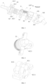
Fig. 1 is a perspective view of a linkage device according to an embodiment of the present invention. -
Fig. 2 is a partially enlarged view of the linkage device inFig. 1 . -
Fig. 3 is a schematic view of a drive component of the linkage device inFig. 2 . -
Fig. 4 is a schematic view of a left end of a first shaft inFig. 3 . -
Fig. 5 is a schematic view of a fixed portion of a damping assembly inFig. 3 . -
Fig. 6 is a schematic view of a movable portion of the damping assembly inFig. 3 . -
Fig. 7 is a schematic view of a stopping member of a limiting assembly inFig. 3 . -
Fig. 8 is a schematic view of the limiting assembly inFig. 3 . -
Fig. 9 is a first schematic view of a transmission assembly inFig. 3 . -
Fig. 10 is a second schematic view of the transmission assembly inFig. 3 . -
Fig. 11 is a schematic view of a first abutting surface on a housing inFig. 3 . -
Fig. 12 is a schematic view of a second abutting surface on a support member inFig. 3 . -
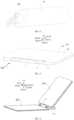
Fig. 13 is a schematic view of an overlapping state of an apparatus accessory according to an embodiment of the present invention. -
Fig. 14 is a schematic view of an unfolded state of an apparatus accessory according to an embodiment of the present invention. -
-
linkage device 100; - overturning
member 1; -
drive component 20; -
first shaft 2; second stoppingportion 21; -
second shaft 3; -
support member 4; second abuttingsurface 41; -
housing 5; first abuttingsurface 51; - limiting
assembly 6; stoppingmember 61;first cam 62; firstperipheral wall 621;guide slot 622;second cam 63; secondperipheral wall 631;snap slot 632; -
transmission assembly 7;incomplete gear 71;first gear 72;second gear 73;first segment 731;second segment 732; - damping
assembly 8; fixedportion 81;first seat 811;first protrusion 8111;second seat 812; first stoppingportion 8121;movable portion 82;elastic member 821;second protrusion 8211; adjustingmember 822; - fixing
member 9;first member 91; slidingslot 911;second member 92;third member 93; - universal joint 10; first joint 101; second joint 102;
fourth member 103; -
protective casing 200;first portion 201;second portion 202. - Embodiments of the present invention are described in detail below, and examples of the described embodiments are shown in the accompanying drawings. The following embodiments described with reference to the accompanying drawings are exemplary and are intended to explain the present invention rather than limit the present invention.
- As shown in
Figs. 1 to 12 , alinkage device 100 according to embodiments of the present invention includes adrive component 20 and asupport member 4. - The
drive component 20 has a transmission stroke and an idle stroke. Thedrive component 20 is rotatable, and during rotation, a rotation stroke of thedrive component 20 is divided into the transmission stroke and the idle stroke. It should be noted that thedrive component 20 can rotate reciprocally, i.e., thedrive component 20 can rotate forward and reversely. During the forward rotation, the rotation stroke of thedrive component 20 is divided into the transmission stroke and the idle stroke. - The
support member 4 is transmissively coupled to thedrive component 20, and thedrive component 20 and thesupport member 4 can rotate synchronously during the rotation of thedrive component 20 during the transmission stroke. During the rotation of thedrive component 20 during the idle stroke, at least a part of thedrive component 20 idles with respect to thesupport member 4. - For example, the
drive component 20 is divided into two component units, namely, a first component unit (i.e., a first shaft described later) and a second component unit (i.e., a second shaft described later). The first component unit can rotate alone relative to thesupport member 4 and the second component unit when thedrive component 20 rotates during the idle stroke. The first component unit, the second component unit and thesupport member 4 can rotate synchronously when thedrive component 20 rotates during the transmission stroke. - It may be understood that in some other embodiments, the transmission between the
drive component 20 and thesupport member 4 can be interrupted when thedrive component 20 rotates during the idle stroke, in which case thedrive component 20 as a whole can rotate relative to thesupport member 4. - The
support member 4 has a retracted position and a support position that are switched by the transmission stroke. That is, when thedrive component 20 rotates during the transmission stroke, thesupport member 4 can rotate along with thedrive component 20 and can be switched between the retracted position and the support position. When thesupport member 4 is switched to the retracted position, thesupport member 4 is suitable for storage, facilitating the storage of thelinkage device 100. When thesupport member 4 is switched to the support position, thesupport member 4 is suitable for stopping and limiting. For example, thesupport member 4 can stop and limit a display screen of an electronic apparatus, avoiding the overturning of the electronic apparatus. - The
linkage device 100 according to embodiments of the present invention has a rotatable connection effect as ordinary hinges, and achieves an effect of linkage between thedrive component 20 and thesupport member 4. That is, thesupport member 4 can be switched to the support position when a rotation function of the hinge is realized. Consequently, thesupport member 4 can support some components (such as the display screen and tablets), avoiding tipping back the electronic apparatus and enhancing the support stability. - In some embodiments, the
drive component 20 includes afirst shaft 2 as the first component unit and asecond shaft 3 as the second component unit, thesecond shaft 3 being coupled to thesupport member 4. During the transmission stroke, thefirst shaft 2, thesecond shaft 3 and thesupport member 4 are transmissively coupled and can rotate synchronously; and during the idle stroke, thefirst shaft 2 and thesecond shaft 3 are transmissively separated to allow thefirst shaft 2 to idle. - As shown in
Fig. 1 , both thefirst shaft 2 and thesecond shaft 3 extend in a left-right direction, and thefirst shaft 2 and thesecond shaft 3 are substantially parallel to each other. Thefirst shaft 2 is rotatable in a direction M inFig. 1 , and during the rotation of thefirst shaft 2, a rotation stroke of thefirst shaft 2 is divided into two stages, namely, a transmission stroke and an idle stroke. During the transmission stroke, thefirst shaft 2 and thesecond shaft 3 are transmissively coupled and can rotate synchronously, in which case thesupport member 4 also rotates synchronously with thesecond shaft 3. During the idle stroke, thefirst shaft 2 and thesecond shaft 3 are transmissively separated, in which case thefirst shaft 2 can continue to rotate, while thesecond shaft 3 and thesupport member 4 remain stationary. - It should be noted that during forward and reverse rotation of the
first shaft 2, the rotation stroke of thefirst shaft 2 can be divided into the transmission stroke and the idle stroke in each case. - In some embodiments, the
linkage device 100 includes an overturningmember 1 coupled to thefirst shaft 2; the overturningmember 1 is configured to drive thefirst shaft 2 to reciprocally rotate; and in the support position, thesupport member 4 stops and limits the overturningmember 1. - As shown in
Fig. 1 , the overturningmember 1 is coupled to a left end of thefirst shaft 2, and the overturningmember 1 cooperates with thefirst shaft 2 in a rotation-resistant manner. In use, by rotating the overturningmember 1, thefirst shaft 2 can be driven to rotate forward in the direction M or can be driven to rotate reversely in a direction opposite to the direction M. - In use, the overturning
member 1 can be coupled to the display screen of the electronic apparatus, or the overturningmember 1 can be integrated with the display screen and considered as a part of the display screen, so that a restraining effect can be achieved by stopping and limiting the overturningmember 1 through thesupport member 4, and the support stability can be ensured. - In some embodiments, in the retracted position, the
support member 4 extends in a same direction as thesecond shaft 3, and in the support position, thesupport member 4 extends at an angle to thesecond shaft 3. - As shown in
Fig. 1 , thesupport member 4 is coupled to thesecond shaft 3 and can rotate synchronously with thesecond shaft 3. Thesupport member 4 is coupled to a right side of thesecond shaft 3 and thesupport member 4 has the retracted position and the support position during rotation. As shown inFig. 1 , in the retracted position, thesupport member 4 extends in the same direction as thesecond shaft 3, i.e., thesupport member 4 also switches to a position extending generally along the left-right direction. - As shown in
Fig. 14 , in the support position, thesupport member 4 and thesecond shaft 3 are at an angle, and thesupport member 4 is fitted with and stops the overturningmember 1. That is, thesupport member 4 can be supported obliquely on the ground or on the table, and a bottom edge of the overturningmember 1 can lap over thesupport member 4, preventing the overturningmember 1 from being suspended after overturning. - With the
linkage device 100 according to embodiments of the present invention, during use, the overturningmember 1 is coupled to the display screen and other components of the electronic apparatus, so that the overturningmember 1 can be supported by thesupport member 4 after the overturningmember 1 has been overturn, enhancing the support stability and avoiding tipping back the electronic apparatus. - During the transmission stroke, the overturning
member 1 drives thesupport member 4 to rotate to the support position through the transmission of thefirst shaft 2 and thesecond shaft 3, then thesupport member 4 remains in the support position, and the overturningmember 1 continues to rotate during the idle stroke, which can satisfy a requirement of opening and closing the overturningmember 1 at a large angle, enrich the angle adjustment of the overturningmember 1 and help to enhance the use convenience. - In some embodiments, the
linkage device 100 includes a limitingassembly 6 that acts between thefirst shaft 2 and thesecond shaft 3. During the idle stroke, the limitingassembly 6 cooperates with thesecond shaft 3 to limit the rotation of thesecond shaft 3. Since thefirst shaft 2 and thesecond shaft 3 are transmissively separated during the idle stroke, thesecond shaft 3 is not restrained by any external force and when thesupport member 4 is subjected to a force, thesecond shaft 3 and thesupport member 4 easily rotate reversely, failing to realize a support effect. - The limiting
assembly 6 can restrain thesecond shaft 3 when thesecond shaft 3 loses the restraint from thefirst shaft 2. As a result, a situation where thesecond shaft 3 rotates at will can be avoided, and thesupport member 4 can realize the support effect; moreover, thefirst shaft 2 can rotate independently of thesecond shaft 3, satisfying the large-angle opening and closing requirement. - In some embodiments, the limiting assembly includes a stopping
member 61. During the transmission stroke, thefirst shaft 2 and thesecond shaft 3 are rotatable with respect to the stoppingmember 61. During the idle stroke, thefirst shaft 2 is rotatable with respect to the stoppingmember 61, and the stoppingmember 61 cooperates with thesecond shaft 3 to limit the rotation of thesecond shaft 3. In other words, the stoppingmember 61 plays a stopping role only during the idle stroke, and restrains thesecond shaft 3 and thesupport member 4 from rotating during the idle stroke of thefirst shaft 2, which realizes a position-limiting effect. - In some embodiments, as shown in
Fig. 8 , the limitingassembly 6 also includes afirst cam 62 and asecond cam 63. - The
first cam 62 is on thefirst shaft 2 and is rotatable synchronously with thefirst shaft 2. An outer peripheral wall of thefirst cam 62 includes a firstperipheral wall 621 and aguide slot 622. Thefirst cam 62 is fitted in an outer peripheral side of thefirst shaft 2 in a rotation-resistant manner. Thefirst cam 62 can rotate synchronously with thefirst shaft 2. Thefirst cam 62 is substantially circular. As shown inFig. 8 , the outer peripheral wall of thefirst cam 62 includes two portions, namely, the firstperipheral wall 621 and theguide slot 622, in which a radial dimension of thefirst cam 62 at the firstperipheral wall 621 is larger than a radial dimension of thefirst cam 62 at theguide slot 622. - The
second cam 63 is fitted with thesecond shaft 3 and is rotatable synchronously with thesecond shaft 3. An outer peripheral wall of thesecond cam 63 includes a secondperipheral wall 631 and asnap slot 632. As shown inFig. 8 , thesecond cam 63 is fitted in an outer peripheral side of thesecond shaft 3 in a rotation-resistant manner. Thesecond cam 63 can rotate synchronously with thefirst shaft 2. Thesecond cam 63 is substantially circular. The outer peripheral wall of thesecond cam 63 includes two portions, namely, the secondperipheral wall 631 and thesnap slot 632, in which a radial dimension of thesecond cam 63 at the secondperipheral wall 631 is larger than a radial dimension of thesecond cam 63 at thesnap slot 632. - During the transmission stroke, the stopping
member 61 is fitted between theguide slot 622 and the secondperipheral wall 631 and the stoppingmember 61 slides along theguide slot 622. As shown inFig. 8 , the stoppingmember 61 is stationary while thefirst shaft 2 rotates during the transmission stroke. As thesecond shaft 3 rotates, the secondperipheral wall 631 of thesecond cam 63 is tangential to the stoppingmember 61 and rotates relative to the stoppingmember 61. Meanwhile, a part of the stoppingmember 61 is fitted in theguide slot 622. As thefirst shaft 2 rotates, the peripheral movement of theguide slot 622 causes relative movement of the stoppingmember 61 in theguide slot 622. - During the idle stroke, the stopping
member 61 is fitted between thesnap slot 632 and the firstperipheral wall 621. As shown inFig. 8 , when thefirst shaft 2 rotates during the idle stroke and thesnap slot 632 on thesecond cam 63 has been rotated to the stoppingmember 61, thesecond cam 63 can be held in position under a stopping action of the stoppingmember 61, and the rotation of thesecond shaft 3 can be limited. Meanwhile, the stoppingmember 61 slides out of theguide slot 622, and the firstperipheral wall 621 of thefirst cam 62 is tangential to the stoppingmember 61 and is rotatable peripherally relative to the stoppingmember 61. Thus, the stoppingmember 61 can be limited in thesnap slot 632 and thefirst shaft 2 can continue to rotate during the idle stroke. - In some embodiments, the stopping
member 61 is slidable between thefirst cam 62 and thesecond cam 63. The stoppingmember 61 slides into the guide slot by a push of the secondperipheral wall 631 when the idle stroke is switched to the transmission stroke. The stoppingmember 61 slides into thesnap slot 632 by a push of the firstperipheral wall 621 when the transmission stroke is switched to the idle stroke. - As shown in
Fig. 2 and inFig. 3 , the limitingassembly 6 is sandwiched between two fixingmembers 9. The fixingmembers 9 are in the form of plates, and the fixingmembers 9 are configured to hold thelinkage device 100 in place. Both thefirst shaft 2 and thesecond shaft 3 pass through the two fixingmembers 9, and rotate and fit with the two fixingmembers 9. As shown inFig. 7 , each fixingmember 9 has a slidingslot 911, and two slidingslots 911 of the two fixingmembers 9 extend in a common direction, both ends of the stoppingmember 61 being sliding and fitted in the corresponding slidingslots 911. - The stopping
member 61 is slidable in an extension direction of the two slidingslots 911. Thus, during the transition of thefirst shaft 2 from the idle stroke to the transmission stroke, the secondperipheral wall 631 of thesecond cam 63 can be pushed against the stoppingmember 61 and push the stoppingmember 61 into theguide slot 622. During the transition of thefirst shaft 2 from the transmission stroke to the idle stroke, the firstperipheral wall 621 of thefirst cam 62 can be pushed against the stoppingmember 61 and push the stoppingmember 61 into thesnap slot 632. The sliding of the stoppingmember 61 satisfies a requirement for limiting the position of thesecond cam 63 and a requirement for the transmission of thefirst shaft 2 and thesecond shaft 3. - In some embodiments, the stopping
member 61 is rotatable; the stoppingmember 61 rolls and is fitted between theguide slot 622 and the secondperipheral wall 631 during the transmission stroke and between thesnap slot 632 and the firstperipheral wall 621 during the idle stroke. As shown inFig. 8 , the stoppingmember 61 is substantially cylindrical in shape, so that the stoppingmember 61 can rotate by itself when thefirst shaft 2 rotates, reducing friction between the stoppingmember 61, and thefirst shaft 2 and the secondperipheral wall 631 and allowing for a smoother rotational drive of thefirst shaft 2. - In some embodiments, as shown in
Fig. 3 , thelinkage device 100 includes atransmission assembly 7 that acts between thefirst shaft 2 and thesecond shaft 3. During the transmission stroke, thefirst shaft 2 is transmissively coupled to thesecond shaft 3 through thetransmission assembly 7, and thefirst shaft 2 and thesecond shaft 3 rotate in a common direction. During the idle stroke, thetransmission assembly 7 is transmissively separated to allow thefirst shaft 2 to idle. The requirement for transmission between thefirst shaft 2 and thesecond shaft 3 can be satisfied. The common rotation direction of thefirst shaft 2 and thesecond shaft 3 allows the overturningmember 1 and thesupport member 4 to rotate in a common direction to satisfy a practical use requirement. - In some embodiments, the
transmission assembly 7 includes anincomplete gear 71, afirst gear 72 and asecond gear 73. Theincomplete gear 71 is on thefirst shaft 2; thefirst gear 72 is on thesecond shaft 3; and thesecond gear 73 transmissively meshes between theincomplete gear 71 and thefirst gear 72. Theincomplete gear 71 meshes with thesecond gear 73 during the transmission stroke, and theincomplete gear 71 is disengaged from thesecond gear 73 during the idle stroke. - As shown in
Fig. 9 , thetransmission assembly 7 is sandwiched between two fixingmembers 9. Theincomplete gear 71 is fitted at an outer peripheral side of thefirst shaft 2 in a rotation-resistant manner. Thefirst gear 72 is fitted at an outer peripheral side of thesecond shaft 3 in a rotation-resistant manner. Thesecond gear 73 is rotatably assembled between the two fixingmembers 9, a first side of thesecond gear 73 meshing with thefirst gear 72 and a second side of thesecond gear 73 meshing with theincomplete gear 71. - During the rotation of the
incomplete gear 71, theincomplete gear 71 can engage with or disengage from thesecond gear 73, satisfying transmission and non-transmission requirements for thefirst shaft 2. - In some embodiments, the
second gear 73 includes afirst segment 731 and asecond segment 732 in an axial direction; theincomplete gear 71 transmissively meshes with thefirst segment 731; and thefirst gear 72 transmissively meshes with thesecond segment 732. As shown inFig. 10 , thesecond gear 73 has a certain extension length in the axial direction (the left-right direction); thefirst segment 731 is a left half of thesecond gear 73 and thesecond segment 732 is the right half of thesecond gear 73; theincomplete gear 71 is on a left side of thefirst gear 72 and meshes with thefirst segment 731; and thesecond gear 73 meshes with thesecond segment 732. As a result, theincomplete gear 71 and thefirst gear 72 are at staggered positions in space, which avoids mutual interference between theincomplete gear 71 and thefirst gear 72, improves the space utilization rate, and facilitates the miniaturization of thelinkage device 100. - In some embodiments, the
linkage device 100 includes a dampingassembly 8; the dampingassembly 8 includes a fixedportion 81 and amovable portion 82; themovable portion 82 is on thefirst shaft 2 and is rotatable along with thefirst shaft 2; and the fixedportion 81 and themovable portion 82 are fitted together to form a damper, so that thefirst shaft 2 can be held in position after thefirst shaft 2 is rotated. - As shown in
Figs. 2 and3 , both the fixedportion 81 and themovable portion 82 are fitted over thefirst shaft 2, in which the fixedportion 81 is rotatable along with thefirst shaft 2 and themovable portion 82 is fitted with thefirst shaft 2 in a rotation-resistant manner. The fixedportion 81 is on a left side of themovable portion 82. When thefirst shaft 2 rotates, the fixedportion 81 remains stationary and themovable portion 82 is rotatable along with thefirst shaft 2. With a damping effect formed between the fixedportion 81 and themovable portion 82, thefirst shaft 2 can rotate at any angle and remain in position after rotation, enabling the overturning member to hover at any position and allowing the user to switch to any angle as required, which is convenient for use. - In some embodiments, the fixed
portion 81 includes afirst protrusion 8111 on its end face abutting against themovable portion 82, and themovable portion 82 includes asecond protrusion 8211 on its end face abutting against the fixedportion 81. During the transmission stroke, thefirst protrusion 8111 is stopped by thesecond protrusion 8211. During the idle stroke, thefirst protrusion 8111 crosses over thesecond protrusion 8211, and themovable portion 82 is elastically retractable to allow thefirst protrusion 8111 to get over thesecond protrusion 8211. - As shown in
Fig. 5 , thefirst protrusion 8111 is at a right end of the fixedportion 81; there are a plurality offirst protrusions 8111, and the plurality offirst protrusions 8111 are spaced apart along a peripheral direction of the fixedportion 81. As shown inFig. 6 , thesecond protrusion 8211 is at a left end of themovable portion 82, and there is a plurality ofsecond protrusions 8211, and the plurality ofsecond protrusions 8211 are spaced along a peripheral direction of themovable portion 82. - In use, the plurality of
first protrusions 8111 and the plurality ofsecond protrusions 8211 are arranged circumferentially in an alternating manner. Consequently, the damping effect of the fixedportion 81 and themovable portion 82 can be enhanced, and when thefirst shaft 2 is rotated to a set angle, thefirst protrusions 8111 can cross over the approachingsecond protrusions 8211, giving the user a sense of feedback and upgrading the operating experience. - Optionally, the
first protrusion 8111 and thesecond protrusion 8211 are guide slopes, allowing thefirst protrusion 8111 and thesecond protrusion 8211 to cross over each other conveniently. - It should be noted that the
movable portion 82 is elastically retractable, so that thefirst protrusion 8111 and thesecond protrusion 8211 can cross over each other by the retraction of themovable portion 82, and themovable portion 82 keeps abutting against the fixedportion 81 by the extension of themovable portion 82 to provide a damping effect. - In some embodiments, the
movable portion 82 includes anelastic member 821 and an adjustingmember 822; theelastic member 821 is fitted over thefirst shaft 2 and is fitted with thefirst shaft 2 in a rotation-resistant manner; theelastic member 821 is sandwiched between the adjustingmember 822 and the fixedportion 81; the adjustingmember 822 is on thefirst shaft 2 with its position being adjustable; the adjustingmember 822 is configured to stop an end of theelastic member 821 and adjust an elastic force of theelastic member 821. - As shown in
Fig. 3 , theelastic member 821 is a disc spring, and theelastic member 821 is fitted over thefirst shaft 2 and fitted with thefirst shaft 2 in a rotation-resistant manner; the adjustingmember 822 is a nut and threadedly fitted on thefirst shaft 2. During use, the adjustingmember 822 stops a right end of theelastic member 821, generating a position-limiting effect; and a left end of theelastic member 821 keeps abutting against the fixedportion 81, generating a damping effect. When the elastic force of theelastic member 821 needs to be adjusted, the adjustingmember 822 can be rotated, and the user can adjust the damping effect according to practical situations. - In some embodiments, the fixed
portion 81 includes a first stoppingportion 8121, and thefirst shaft 2 includes a second stoppingportion 21. The first stoppingportion 8121 is fitted with and stopped by the second stoppingportion 21, to limit the rotation stroke of thefirst shaft 2. As shown inFig. 4 , the first stoppingportion 8121 is fan-shaped and integrated with the fixedportion 81, and the second stoppingportion 21 is also fan-shaped and integrated with thefirst shaft 2. In use, the first stoppingportion 8121 can be stopped by the second stoppingportion 21 to limit a maximum rotation stroke of thefirst shaft 2. - In some embodiments, the
linkage device 100 includes ahousing 5. Thehousing 5 has a first abuttingsurface 51, and thesupport member 4 has a second abuttingsurface 41. The first abuttingsurface 51 abuts against the second abuttingsurface 41 in both the retracted position and the support position. - As shown in
Fig. 11 , thehousing 5 is cylindrical and the first abuttingsurface 51 is elliptical. As shown inFig. 12 , thesupport member 4 is also substantially cylindrical and the second abuttingsurface 41 is also elliptical. Thesupport member 4 is rotatable by 180 degrees along with thesecond shaft 3. Thus, in the retracted position, the first abuttingsurface 51 abuts against the second abuttingsurface 41, and thehousing 5 and thesupport member 4 are assembled into a cylindrical body as a whole, enhancing integration and aesthetics and facilitating storage. In the support position, the second abuttingsurface 41 is rotated by 180 degrees and abuts against the first abuttingsurface 51, in which case thehousing 5 and thesupport member 4 are at an angle to meet the need for support and use. - In some embodiments, as shown in
Fig. 3 , thesecond shaft 3 is coupled to thesupport member 4 by auniversal joint 10. Theuniversal joint 10 includes a first joint 101 and a second joint 102, the first joint 101 being coupled to thesecond shaft 3 and the second joint 102 being coupled to thesupport member 4. An axial direction of the first joint 101 is at a first angle to an axial direction of the second joint 102, in which the first angle is an obtuse angle. - The second joint 102 is rotatably assembled with the
housing 5, and both the first abuttingsurface 51 and the second abuttingsurface 41 are at a second angle to the axial direction of the second joint 102, in which the second angel is a right angle. That is, both the first abuttingsurface 51 and the second abuttingsurface 41 are perpendicular to the axial direction of thesecond joint 102. Thus, a requirement for different transmission axes and a requirement for transmission between thesecond shaft 3 and thesupport member 4 can be satisfied. - In some embodiments, the
linkage device 100 includes a plurality of fixingmembers 9. Thefirst shaft 2 is rotatably fitted with at least part of the fixingmembers 9, and thesecond shaft 3 is rotatably fitted with at least part of the fixingmembers 9. Thefirst shaft 2 and thesecond shaft 3 are assembled in thehousing 5 by the plurality of fixingmembers 9. - As shown in
Figs. 2 and3 , there are four fixing members, including afirst member 91, asecond member 92, athird member 93 and afourth member 103. Thefirst member 91 and thesecond member 92 are assembled in a part where thefirst shaft 2 and thesecond shaft 3 overlap in the left-right direction. Thefirst member 91 is on a left side of thesecond member 92 and is spaced apart from thesecond member 92. Both thefirst shaft 2 and thesecond shaft 3 are rotatably fitted with thefirst member 91 and thesecond member 92. The limitingassembly 6 and thetransmission assembly 7 are between thefirst member 91 and thesecond member 92 and are separated by a partition plate that may also be regarded as one fixingmember 9. - As shown in
Fig. 3 , each of thethird member 93 and thefourth member 103 includes a sleeve; thethird member 93 is on a right side of thesecond member 92; thesecond shaft 3 is rotatably assembled within the sleeve of thethird member 93; thefourth member 103 is on a right side of thethird member 93; and the second joint 102 is rotatably assembled within the sleeve of thefourth member 103. - The
first member 91, thesecond member 92, thethird member 93, and thefourth member 103 are all coupled to thehousing 5, enabling the mounting and fixing of thelinkage device 100 to thehousing 5. - In some embodiments, as shown in
Fig. 5 , the fixedportion 81 has a split structure, and the fixedportion 81 includes afirst seat 811 and asecond seat 812. Thefirst seat 811 is on a right side of thesecond seat 812, thesecond seat 812 is fixedly coupled to thehousing 5. Thefirst seat 811 is rotatably coupled to thesecond seat 812 via a pin, such that thefirst seat 811 has a certain degree of freedom and its adaptability to themovable portion 82 is enhanced. - In some embodiments, a central angle corresponding to the
guide slot 622 is 90°, and a total rotation angle of thefirst shaft 2 is 130°. The stoppingmember 61 moves along theguide slot 622 as thefirst shaft 2 rotates during the transmission stroke, in which case thefirst shaft 2 rotates by 90° and thesupport member 4 rotates by 180° under a transmission effect of thesecond shaft 3. Thefirst shaft 2 transitions to the idle stroke and continues to rotate to 130°, in which case the first stoppingportion 8121 and the second stoppingportion 21 are stopped by each other for position limiting. - An apparatus accessory according to embodiments of the present invention will be described below.
- The apparatus accessory according to embodiments of the present invention includes a
linkage device 100, which may be thelinkage device 100 described in the above embodiments. As shown inFigs. 13 and 14 , the apparatus accessory includes aprotective casing 200, and theprotective casing 200 includes afirst portion 201 and asecond portion 202. Thefirst portion 201 is swingable with respect to thesecond portion 202, and thefirst portion 201 is coupled to the overturningmember 1, in which case the overturningmember 1 may be regarded as a part of thefirst portion 201. Thesecond portion 202 is coupled to thehousing 5, which may also be regarded as a part of thesecond portion 202. - In use, the
first portion 201 can be overturn from back to front, and thefirst portion 201 drives the overturningmember 1, and in turn drives thefirst shaft 2, thesecond shaft 3 and thesupport member 4 to rotate synchronously. When thefirst portion 201 is overturn to a position as shown inFig. 14 , thesupport member 4 is propped up between a tabletop and a lower edge of thefirst portion 201, providing a support effect for thefirst portion 201. - When the apparatus accessory needs to be stored, the
first portion 201 can be overturn backwards, and during the idle stroke, only thefirst portion 201, the overturningmember 1 and thefirst shaft 2 rotate backwards. After the transition to the transmission stroke, thesecond shaft 3 and thesupport member 4 can rotate backwards along with thefirst portion 201 until thefirst portion 201 from the above overlaps thesecond portion 202, in which case thesupport member 4 is switched to a storage position, as shown inFig. 13 . - It is to be noted that the
first portion 201 and thesecond portion 202 are two separate portions, and thefirst portion 201 and thesecond portion 202 are flexibly coupled to meet a requirement for relative rotation of thefirst portion 201 and thesecond portion 202. - In some embodiments, as shown in
Figs. 13 and 14 , there are twolinkage devices 100, and the twolinkage devices 100 share one overturningmember 1, in which case the overturningmember 1 is between the twolinkage devices 100, improving symmetry, in turn enhancing the support stability. - An electronic apparatus according to embodiments of the present invention will be described below.
- The electronic apparatus according to embodiments of the present invention includes only the
linkage device 100 described in the above embodiments. For example, the electronic apparatus is a notebook that includes a display screen and a keyboard, the display screen and the keyboard being rotatably coupled to each other using thelinkage device 100. - In some other embodiments, the electronic apparatus may include the apparatus accessory described in the above embodiments. For example, the electronic apparatus includes a tablet and a split keyboard, the tablet being fixed to the
first portion 201 of the apparatus accessory and the split keyboard being fixed to thesecond portion 202 of the apparatus accessory. - In the description of the present invention, it shall be understood that terms such as "central," "longitudinal," "transverse," "length," "width," "thickness," "upper," "lower," "front," "rear," "left," "right," "vertical," "horizontal," "top," "bottom," "inner," "outer," "clockwise," "counterclockwise," "axial," "radial" and "circumferential" should be construed to refer to the orientation as then described or as shown in the drawings under discussion. These relative terms are for convenience of description and do not indicate or imply that the device or element referred to must have a particular orientation, or be constructed and operated in a particular orientation. Thus, these terms shall not be construed as limitation on the present invention.
- In addition, terms such as "first" and "second" are merely used for descriptive purposes and cannot be understood as indicating or implying relative importance or the number of technical features indicated. Thus, the features associated with "first" and "second" may explicitly or implicitly include at least one of the features. In the description of the present invention, unless otherwise specifically defined, "a plurality of' means at least two, such as two, three, etc.
- In the present invention, unless otherwise explicitly specified and defined, the terms "mounted," "coupled," "connected," "fixed" and the like are used broadly, and may be, for example, fixed connections, detachable connections, or integral connections; may also be mechanical or electrical connections or intercommunication; may also be direct connections or indirect connections via intermediate media; may also be inner communications or interactions of two elements. For those skilled in the art, the specific meaning of the above terms in the present invention can be understood according to the specific circumstances.
- In the present invention, unless otherwise explicitly specified and defined, a structure in which a first feature is "on" or "below" a second feature may include an embodiment in which the first feature is in direct contact with the second feature, and may also include an embodiment in which the first feature and the second feature are not in direct contact with each other, but are contacted via an intermediate medium formed therebetween. Furthermore, a first feature "on," "above," or "on top of' a second feature may include an embodiment in which the first feature is right or obliquely "on," "above," or "on top of' the second feature, or just means that the first feature is at a height higher than that of the second feature; while a first feature "below," "under," or "on bottom of' a second feature may include an embodiment in which the first feature is right or obliquely "below," "under," or "on bottom of' the second feature, or just means that the first feature is at a height lower than that of the second feature.
- In the present invention, terms such as "an embodiment," "some embodiments," "an example," "a specific example," or "some examples," means that a particular feature, structure, material, or characteristic described in connection with embodiment or example is included in at least one embodiment or example of the present invention. Thus, the appearances of these terms in various places throughout this specification are not necessarily referring to the same embodiment or example of the present invention. Furthermore, the particular features, structures, materials, or characteristics may be combined in any suitable manner in one or more embodiments or examples. In addition, without contradiction, those skilled in the art may combine and unite different embodiments or examples or features of the different embodiments or examples described in this specification.
- Although the above embodiments have been shown and described, it can be understood that the above embodiments are exemplary and shall not be understood as limitation to the present invention, and changes, modifications, alternatives, and variations can be made in the above embodiments within the scope of the present invention.
Claims (15)
- A linkage device (100), comprising:a drive component (20) rotatable during a transmission stroke and an idle stroke; anda support member (4) coupled to the drive component (20),wherein:the drive component (20) and the support member (4) are configured to rotate synchronously during the transmission stroke, and at least a part of the drive component (20) idles with respect to the support member (4) during the idle stroke; andthe support member (4) has (i) a retracted position in which the support member (4) is suitable for storage and (ii) a support position in which the support member (4) is suitable for stopping and limiting, wherein the retracted position and the support position are switched by the transmission stroke.
- The linkage device (100) according to claim 1, wherein:the drive component (20) comprises a first shaft (2) and a second shaft (3), the second shaft (3) being coupled to the support member (4);during the transmission stroke, the first shaft (2), the second shaft (3) and the support member (4) are transmissively coupled and rotate synchronously; andduring the idle stroke, the first shaft (2) and the second shaft (3) are transmissively separated and the first shaft (2) idles.
- The linkage device (100) according to claim 2, further comprising an overturning member (1) coupled to the first shaft (2), wherein the overturning member (1) is configured to drive the first shaft (2) to reciprocally rotate, and in the support position, the support member (4) stops and limits the overturning member (1).
- The linkage device (100) according to claim 2 or 3, wherein the support member (4) extends in a same direction as the second shaft (3) in the retracted position, and the support member (4) extends at an angle to the second shaft (3) in the support position.
- The linkage device (100) according to any one of claims 2 to 4, comprising a limiting assembly (6),wherein:the limiting assembly (6) is configured to act between the first shaft (2) and the second shaft (3); andduring the idle stroke, the limiting assembly (6) is configured to cooperate with the second shaft (3) to limit rotation of the second shaft (3),optionally, wherein:the limiting assembly (6) comprises a stopping member (61);during the transmission stroke, the first shaft (2) and the second shaft (3) are rotatable with respect to the stopping member (61); andduring the idle stroke, the first shaft (2) is rotatable with respect to the stopping member (61), and the stopping member (61) is configured to cooperate with the second shaft (3) to limit the rotation of the second shaft (3).
- The linkage device (100) according to claim 5, wherein the limiting assembly (6) comprises:a first cam (62) on the first shaft (2) and being rotatable synchronously with the first shaft (2), an outer peripheral wall of the first cam (62) comprising a first peripheral wall (621) and a guide slot (622); anda second cam (63) on the second shaft (3) and being rotatable synchronously with the second shaft (3), an outer peripheral wall of the second cam (63) comprising a second peripheral wall (631) and a snap slot (632);wherein:during the transmission stroke, the stopping member (61) is fitted between the guide slot (622) and the second peripheral wall (631) and is configured to slide along the guide slot (622); andduring the idle stroke, the stopping member (61) is fitted between the snap slot (632) and the first peripheral wall (621).
- The linkage device (100) according to claim 6, wherein:the stopping member (61) is slidable between the first cam (62) and the second cam (63);the stopping member (61) is configured to slide into the guide slot (622) by a push of the second peripheral wall (631) during a switch from the idle stroke to the transmission stroke; andthe stopping member (61) is configured to slide into the snap slot (632) by a push of the first peripheral wall (621) during a switch from the transmission stroke to the idle stroke.
- The linkage device (100) according to claim 6, wherein:the stopping member (61) is rotatable;the stopping member (61) is configured to roll and is fitted between the guide slot (622) and the second peripheral wall (631) during the transmission stroke; andthe stopping member (61) is configured to roll and is fitted between the snap slot (632) and the first peripheral wall (621) during the idle stroke.
- The linkage device (100) according to any one of claims 2 to 8, comprising a transmission assembly (7) acting between the first shaft (2) and the second shaft (3),wherein:during the transmission stroke, the first shaft (2) is transmissively coupled to the second shaft (3) through the transmission assembly, and the first shaft (2) and the second shaft (3) rotate in a common direction; andduring the idle stroke, the transmission assembly is transmissively separated to allow the first shaft (2) to idle,optionally, wherein the transmission assembly comprises:an incomplete gear (71) on the first shaft (2);a first gear (72) on the second shaft (3); anda second gear (73) transmissively meshing between the incomplete gear (71) and the first gear (72),wherein the incomplete gear (71) is configured to transmissively mesh with the second gear (73) with during the transmission stroke and is configured to be disengaged from the second gear (73) during the idle stroke,optionally, wherein the second gear (73) comprises a first segment (731) and a second segment (732) in an axial direction; the incomplete gear (71) transmissively meshes with the first segment (731); and the first gear (72) transmissively meshes with the second segment (732).
- The linkage device (100) according to any one of claims 2 to 9, comprising a damping assembly (8),
wherein:the damping assembly (8) comprises a fixed portion (81) and a movable portion (82);the movable portion (82) is on the first shaft (2) and is rotatable along with the first shaft (2); andthe fixed portion (81) and the movable portion (82) are fitted together to form a damper, and the first shaft (2) is held in position after rotation. - The linkage device (100) according to claim 10, wherein:the fixed portion (81) comprises a first protrusion (8111) on an end face abutting against the movable portion (82), and the movable portion (82) comprises a second protrusion (8211) on an end face abutting against the fixed portion (81);during the transmission stroke, the first protrusion (8111) is configured to be stopped by the second protrusion (8211); andduring the idle stroke, the first protrusion (8111) is configured to cross over the second protrusion (8211), and the movable portion (82) is elastically retractable to allow the first protrusion (8111) to get over the second protrusion (8211),optionally, wherein the movable portion (82) comprises:an elastic member (821) fitted over the first shaft (2) and fitted with the first shaft (2) in a rotation-resistant manner; andan adjusting member (822) on the first shaft (2) with a position of the adjusting member (822) being adjustable,wherein the elastic member (821) is sandwiched between the adjusting member (822) and the fixed portion (81), and the adjusting member (822) is configured to stop an end of the elastic member (821) and adjust an elastic force of the elastic member (821).
- The linkage device (100) according to claim 10, wherein the fixed portion (81) comprises a first stopping portion (8121), and the first shaft (2) comprises a second stopping portion (21), the first stopping portion (8121) being fitted with and stopped by the second stopping portion (21) to limit a rotation stroke of the first shaft (2).
- The linkage device (100) according to any one of claims 2 to 12, comprising a housing (5),wherein the housing (5) has a first abutting surface (51), the support member (4) has a second abutting surface (41), and the first abutting surface (51) abuts against the second abutting surface (41) in both the retracted position and the support position,optionally, wherein:the second shaft (3) is coupled to the support member (4) by a universal joint (10);the universal joint (10) comprises a first joint (101) and a second joint (102), the first joint (101) being coupled to the second shaft (3) and the second joint (102) being coupled to the support member (4);an axial direction of the first joint (101) is at a first angle to an axial direction of the second joint (102);the second joint (102) is rotatably assembled with the housing (5); andthe first abutting surface (51) and the second abutting surface (41) are at a second angle to the axial direction of the second joint (102).
- An apparatus accessory, comprising:the linkage device (100) according to any one of claims 1 to 13; anda protective casing (200),wherein:the protective casing (200) comprises a first portion (201) and a second portion (202);the first portion (201) is swingable with respect to the second portion (202), and the first portion (201) is coupled to an overturning member (1) of the linkage device (100); andthe second portion (202) is coupled to a housing (5) of the linkage device (100).
- An electronic apparatus, comprising:the linkage device (100) according to any one of claims 1 to 13 or the apparatus accessory according to claim 14; anda display screen coupled to the linkage device (100).
Applications Claiming Priority (1)
| Application Number | Priority Date | Filing Date | Title |
|---|---|---|---|
| CN202210524591.7A CN117091055A (en) | 2022-05-13 | 2022-05-13 | Linkages, equipment accessories and electronic equipment |
Publications (2)
| Publication Number | Publication Date |
|---|---|
| EP4276574A1 true EP4276574A1 (en) | 2023-11-15 |
| EP4276574B1 EP4276574B1 (en) | 2025-07-23 |
Family
ID=83270812
Family Applications (1)
| Application Number | Title | Priority Date | Filing Date |
|---|---|---|---|
| EP22192632.2A Active EP4276574B1 (en) | 2022-05-13 | 2022-08-29 | Linkage device, apparatus accessory and electronic apparatus |
Country Status (5)
| Country | Link |
|---|---|
| US (1) | US12117877B2 (en) |
| EP (1) | EP4276574B1 (en) |
| JP (1) | JP7430755B2 (en) |
| KR (1) | KR102798926B1 (en) |
| CN (1) | CN117091055A (en) |
Families Citing this family (1)
| Publication number | Priority date | Publication date | Assignee | Title |
|---|---|---|---|---|
| TWM636243U (en) * | 2022-10-07 | 2023-01-01 | 華碩電腦股份有限公司 | Foldable electronic device |
Citations (4)
| Publication number | Priority date | Publication date | Assignee | Title |
|---|---|---|---|---|
| US20150293562A1 (en) * | 2014-04-15 | 2015-10-15 | Fujitsu Limited | Overturn prevention device for apparatus including tiltable housing |
| CN106125841A (en) * | 2016-06-27 | 2016-11-16 | 联想(北京)有限公司 | Electronic equipment |
| US20180119467A1 (en) * | 2016-11-03 | 2018-05-03 | Wistron Corporation | Hinge module and assembling method |
| US20220147112A1 (en) * | 2020-11-10 | 2022-05-12 | Wistron Corp. | Electronic device and linked hinge mechanism thereof |
Family Cites Families (14)
| Publication number | Priority date | Publication date | Assignee | Title |
|---|---|---|---|---|
| US20070001074A1 (en) * | 2005-06-30 | 2007-01-04 | Jaeho Choi | Stabilizing apparatus for a portable electronic device |
| KR101052636B1 (en) * | 2009-03-11 | 2011-07-29 | 엘에스산전 주식회사 | Balance entry / exit prevention device of circuit breaker |
| US8333127B2 (en) * | 2009-05-20 | 2012-12-18 | GM Global Technology Operations LLC | Seven speed dual clutch transmission with four axes of rotation |
| KR101046657B1 (en) * | 2009-11-10 | 2011-07-05 | 주식회사 케이에이치바텍 | Damping hinge module |
| KR20130024489A (en) * | 2011-08-31 | 2013-03-08 | 에릭슨 엘지 주식회사 | Support device for portable electronic device and portable electronic device with the same |
| CN103796460A (en) * | 2012-10-30 | 2014-05-14 | 鸿富锦精密工业(深圳)有限公司 | Supporting device |
| JP6167763B2 (en) | 2013-08-28 | 2017-07-26 | 富士通株式会社 | Information processing device |
| JP2015184901A (en) | 2014-03-24 | 2015-10-22 | 株式会社東芝 | Electronics |
| JP6323698B1 (en) | 2017-03-16 | 2018-05-16 | Vaio株式会社 | Information equipment |
| KR102464684B1 (en) * | 2018-05-09 | 2022-11-09 | 삼성전자주식회사 | Electronic device with hinge assembly |
| TWI710308B (en) * | 2019-02-16 | 2020-11-11 | 兆利科技工業股份有限公司 | A hinge module for the foldable type device |
| JP7227402B2 (en) * | 2019-04-18 | 2023-02-21 | 華為技術有限公司 | Rotating display device for electronic devices |
| JP7668516B2 (en) * | 2020-10-29 | 2025-04-25 | 株式会社ナチュラレーザ・ワン | Multi-axis hinge device and electronic device using the multi-axis hinge device |
| TWM617297U (en) * | 2021-04-23 | 2021-09-21 | 宏碁股份有限公司 | Foldable electronic device |
-
2022
- 2022-05-13 CN CN202210524591.7A patent/CN117091055A/en active Pending
- 2022-08-25 JP JP2022134135A patent/JP7430755B2/en active Active
- 2022-08-26 US US17/896,941 patent/US12117877B2/en active Active
- 2022-08-26 KR KR1020220107368A patent/KR102798926B1/en active Active
- 2022-08-29 EP EP22192632.2A patent/EP4276574B1/en active Active
Patent Citations (4)
| Publication number | Priority date | Publication date | Assignee | Title |
|---|---|---|---|---|
| US20150293562A1 (en) * | 2014-04-15 | 2015-10-15 | Fujitsu Limited | Overturn prevention device for apparatus including tiltable housing |
| CN106125841A (en) * | 2016-06-27 | 2016-11-16 | 联想(北京)有限公司 | Electronic equipment |
| US20180119467A1 (en) * | 2016-11-03 | 2018-05-03 | Wistron Corporation | Hinge module and assembling method |
| US20220147112A1 (en) * | 2020-11-10 | 2022-05-12 | Wistron Corp. | Electronic device and linked hinge mechanism thereof |
Also Published As
| Publication number | Publication date |
|---|---|
| US12117877B2 (en) | 2024-10-15 |
| JP2023168190A (en) | 2023-11-24 |
| EP4276574B1 (en) | 2025-07-23 |
| US20230367375A1 (en) | 2023-11-16 |
| KR20230159213A (en) | 2023-11-21 |
| JP7430755B2 (en) | 2024-02-13 |
| CN117091055A (en) | 2023-11-21 |
| KR102798926B1 (en) | 2025-04-23 |
Similar Documents
| Publication | Publication Date | Title |
|---|---|---|
| JP7607299B2 (en) | Hinge mechanism and electronic device | |
| CN113923279A (en) | Folding assembly and foldable electronic equipment | |
| CN110138916B (en) | A rotating device and mobile terminal | |
| WO2021007914A1 (en) | Bendable device | |
| TWI609135B (en) | Hinge device, folding device and portable terminal | |
| CN113898665A (en) | Hinge assembly and electronic device | |
| US9309705B2 (en) | Dual-shaft synchronous transmission fixing device | |
| WO2022135281A1 (en) | Electronic device | |
| CN112751961A (en) | Folding mechanism and electronic equipment | |
| EP4276574A1 (en) | Linkage device, apparatus accessory and electronic apparatus | |
| TW201330749A (en) | Connecting mechanism and related electronic device | |
| JP2024539577A (en) | Support assembly, protection mechanism, motor assembly and electronic device | |
| US11550359B2 (en) | Electronic device | |
| CN108883823B (en) | Arm locking mechanism and aircraft | |
| TWI519934B (en) | Docking device and electronic system therewith | |
| CN110879643B (en) | Hinged structure and foldable electronic device | |
| CN117128239A (en) | Hinge assemblies and foldable devices | |
| WO2025107600A1 (en) | Pivot mechanism and foldable electronic device | |
| EP4285200B1 (en) | Support arrangement for foldable electronic apparatus | |
| CN115263906B (en) | Electronic equipment and rotating shaft mechanism thereof | |
| JP3116757U (en) | Operation panel device | |
| CN112732020A (en) | Electronic equipment | |
| WO2021221662A1 (en) | Adjusting mechanisms for flexible display panels | |
| KR102643878B1 (en) | Hinge device for a portable terminal with a foldable structure | |
| KR20110005117A (en) | Hinge device for mobile terminal |
Legal Events
| Date | Code | Title | Description |
|---|---|---|---|
| PUAI | Public reference made under article 153(3) epc to a published international application that has entered the european phase |
Free format text: ORIGINAL CODE: 0009012 |
|
| STAA | Information on the status of an ep patent application or granted ep patent |
Free format text: STATUS: REQUEST FOR EXAMINATION WAS MADE |
|
| 17P | Request for examination filed |
Effective date: 20220829 |
|
| AK | Designated contracting states |
Kind code of ref document: A1 Designated state(s): AL AT BE BG CH CY CZ DE DK EE ES FI FR GB GR HR HU IE IS IT LI LT LU LV MC MK MT NL NO PL PT RO RS SE SI SK SM TR |
|
| GRAP | Despatch of communication of intention to grant a patent |
Free format text: ORIGINAL CODE: EPIDOSNIGR1 |
|
| STAA | Information on the status of an ep patent application or granted ep patent |
Free format text: STATUS: GRANT OF PATENT IS INTENDED |
|
| INTG | Intention to grant announced |
Effective date: 20250225 |
|
| P01 | Opt-out of the competence of the unified patent court (upc) registered |
Free format text: CASE NUMBER: APP_21383/2025 Effective date: 20250506 |
|
| GRAS | Grant fee paid |
Free format text: ORIGINAL CODE: EPIDOSNIGR3 |
|
| GRAA | (expected) grant |
Free format text: ORIGINAL CODE: 0009210 |
|
| STAA | Information on the status of an ep patent application or granted ep patent |
Free format text: STATUS: THE PATENT HAS BEEN GRANTED |
|
| AK | Designated contracting states |
Kind code of ref document: B1 Designated state(s): AL AT BE BG CH CY CZ DE DK EE ES FI FR GB GR HR HU IE IS IT LI LT LU LV MC MK MT NL NO PL PT RO RS SE SI SK SM TR |
|
| REG | Reference to a national code |
Ref country code: GB Ref legal event code: FG4D |
|
| REG | Reference to a national code |
Ref country code: CH Ref legal event code: EP |
|
| REG | Reference to a national code |
Ref country code: DE Ref legal event code: R096 Ref document number: 602022017944 Country of ref document: DE |
|
| REG | Reference to a national code |
Ref country code: IE Ref legal event code: FG4D |
|
| PGFP | Annual fee paid to national office [announced via postgrant information from national office to epo] |
Ref country code: DE Payment date: 20250820 Year of fee payment: 4 |
|
| PGFP | Annual fee paid to national office [announced via postgrant information from national office to epo] |
Ref country code: AT Payment date: 20251020 Year of fee payment: 4 |
|
| REG | Reference to a national code |
Ref country code: NL Ref legal event code: MP Effective date: 20250723 |
|
| PG25 | Lapsed in a contracting state [announced via postgrant information from national office to epo] |
Ref country code: PT Free format text: LAPSE BECAUSE OF FAILURE TO SUBMIT A TRANSLATION OF THE DESCRIPTION OR TO PAY THE FEE WITHIN THE PRESCRIBED TIME-LIMIT Effective date: 20251124 |
|
| PG25 | Lapsed in a contracting state [announced via postgrant information from national office to epo] |
Ref country code: NL Free format text: LAPSE BECAUSE OF FAILURE TO SUBMIT A TRANSLATION OF THE DESCRIPTION OR TO PAY THE FEE WITHIN THE PRESCRIBED TIME-LIMIT Effective date: 20250723 |
|
| REG | Reference to a national code |
Ref country code: AT Ref legal event code: MK05 Ref document number: 1817068 Country of ref document: AT Kind code of ref document: T Effective date: 20250723 |
|
| PG25 | Lapsed in a contracting state [announced via postgrant information from national office to epo] |
Ref country code: IS Free format text: LAPSE BECAUSE OF FAILURE TO SUBMIT A TRANSLATION OF THE DESCRIPTION OR TO PAY THE FEE WITHIN THE PRESCRIBED TIME-LIMIT Effective date: 20251123 |
|
| PG25 | Lapsed in a contracting state [announced via postgrant information from national office to epo] |
Ref country code: NO Free format text: LAPSE BECAUSE OF FAILURE TO SUBMIT A TRANSLATION OF THE DESCRIPTION OR TO PAY THE FEE WITHIN THE PRESCRIBED TIME-LIMIT Effective date: 20251023 |
|
| REG | Reference to a national code |
Ref country code: LT Ref legal event code: MG9D |
|
| PG25 | Lapsed in a contracting state [announced via postgrant information from national office to epo] |
Ref country code: AT Free format text: LAPSE BECAUSE OF FAILURE TO SUBMIT A TRANSLATION OF THE DESCRIPTION OR TO PAY THE FEE WITHIN THE PRESCRIBED TIME-LIMIT Effective date: 20250723 |
|
| PG25 | Lapsed in a contracting state [announced via postgrant information from national office to epo] |
Ref country code: FI Free format text: LAPSE BECAUSE OF FAILURE TO SUBMIT A TRANSLATION OF THE DESCRIPTION OR TO PAY THE FEE WITHIN THE PRESCRIBED TIME-LIMIT Effective date: 20250723 |
|
| PG25 | Lapsed in a contracting state [announced via postgrant information from national office to epo] |
Ref country code: HR Free format text: LAPSE BECAUSE OF FAILURE TO SUBMIT A TRANSLATION OF THE DESCRIPTION OR TO PAY THE FEE WITHIN THE PRESCRIBED TIME-LIMIT Effective date: 20250723 |
|
| PG25 | Lapsed in a contracting state [announced via postgrant information from national office to epo] |
Ref country code: GR Free format text: LAPSE BECAUSE OF FAILURE TO SUBMIT A TRANSLATION OF THE DESCRIPTION OR TO PAY THE FEE WITHIN THE PRESCRIBED TIME-LIMIT Effective date: 20251024 |
|
| PG25 | Lapsed in a contracting state [announced via postgrant information from national office to epo] |
Ref country code: SE Free format text: LAPSE BECAUSE OF FAILURE TO SUBMIT A TRANSLATION OF THE DESCRIPTION OR TO PAY THE FEE WITHIN THE PRESCRIBED TIME-LIMIT Effective date: 20250723 |
|
| PG25 | Lapsed in a contracting state [announced via postgrant information from national office to epo] |
Ref country code: LV Free format text: LAPSE BECAUSE OF FAILURE TO SUBMIT A TRANSLATION OF THE DESCRIPTION OR TO PAY THE FEE WITHIN THE PRESCRIBED TIME-LIMIT Effective date: 20250723 |
|
| PG25 | Lapsed in a contracting state [announced via postgrant information from national office to epo] |
Ref country code: PL Free format text: LAPSE BECAUSE OF FAILURE TO SUBMIT A TRANSLATION OF THE DESCRIPTION OR TO PAY THE FEE WITHIN THE PRESCRIBED TIME-LIMIT Effective date: 20250723 Ref country code: BG Free format text: LAPSE BECAUSE OF FAILURE TO SUBMIT A TRANSLATION OF THE DESCRIPTION OR TO PAY THE FEE WITHIN THE PRESCRIBED TIME-LIMIT Effective date: 20250723 |
|
| PG25 | Lapsed in a contracting state [announced via postgrant information from national office to epo] |
Ref country code: RS Free format text: LAPSE BECAUSE OF FAILURE TO SUBMIT A TRANSLATION OF THE DESCRIPTION OR TO PAY THE FEE WITHIN THE PRESCRIBED TIME-LIMIT Effective date: 20251023 |
|
| PG25 | Lapsed in a contracting state [announced via postgrant information from national office to epo] |
Ref country code: ES Free format text: LAPSE BECAUSE OF FAILURE TO SUBMIT A TRANSLATION OF THE DESCRIPTION OR TO PAY THE FEE WITHIN THE PRESCRIBED TIME-LIMIT Effective date: 20250723 |
|
| PG25 | Lapsed in a contracting state [announced via postgrant information from national office to epo] |
Ref country code: RO Free format text: LAPSE BECAUSE OF FAILURE TO SUBMIT A TRANSLATION OF THE DESCRIPTION OR TO PAY THE FEE WITHIN THE PRESCRIBED TIME-LIMIT Effective date: 20250723 |
|
| REG | Reference to a national code |
Ref country code: CH Ref legal event code: H13 Free format text: ST27 STATUS EVENT CODE: U-0-0-H10-H13 (AS PROVIDED BY THE NATIONAL OFFICE) Effective date: 20260324 |
|
| PG25 | Lapsed in a contracting state [announced via postgrant information from national office to epo] |
Ref country code: SM Free format text: LAPSE BECAUSE OF FAILURE TO SUBMIT A TRANSLATION OF THE DESCRIPTION OR TO PAY THE FEE WITHIN THE PRESCRIBED TIME-LIMIT Effective date: 20250723 |
|
| PG25 | Lapsed in a contracting state [announced via postgrant information from national office to epo] |
Ref country code: DK Free format text: LAPSE BECAUSE OF FAILURE TO SUBMIT A TRANSLATION OF THE DESCRIPTION OR TO PAY THE FEE WITHIN THE PRESCRIBED TIME-LIMIT Effective date: 20250723 |
|
| PG25 | Lapsed in a contracting state [announced via postgrant information from national office to epo] |
Ref country code: LU Free format text: LAPSE BECAUSE OF NON-PAYMENT OF DUE FEES Effective date: 20250829 Ref country code: IT Free format text: LAPSE BECAUSE OF FAILURE TO SUBMIT A TRANSLATION OF THE DESCRIPTION OR TO PAY THE FEE WITHIN THE PRESCRIBED TIME-LIMIT Effective date: 20250723 |
|
| PG25 | Lapsed in a contracting state [announced via postgrant information from national office to epo] |
Ref country code: CH Free format text: LAPSE BECAUSE OF NON-PAYMENT OF DUE FEES Effective date: 20250831 Ref country code: CZ Free format text: LAPSE BECAUSE OF FAILURE TO SUBMIT A TRANSLATION OF THE DESCRIPTION OR TO PAY THE FEE WITHIN THE PRESCRIBED TIME-LIMIT Effective date: 20250723 |
|
| PG25 | Lapsed in a contracting state [announced via postgrant information from national office to epo] |
Ref country code: SK Free format text: LAPSE BECAUSE OF FAILURE TO SUBMIT A TRANSLATION OF THE DESCRIPTION OR TO PAY THE FEE WITHIN THE PRESCRIBED TIME-LIMIT Effective date: 20250723 Ref country code: EE Free format text: LAPSE BECAUSE OF FAILURE TO SUBMIT A TRANSLATION OF THE DESCRIPTION OR TO PAY THE FEE WITHIN THE PRESCRIBED TIME-LIMIT Effective date: 20250723 |