EP4276503A1 - Optical fiber - Google Patents
Optical fiber Download PDFInfo
- Publication number
- EP4276503A1 EP4276503A1 EP21917410.9A EP21917410A EP4276503A1 EP 4276503 A1 EP4276503 A1 EP 4276503A1 EP 21917410 A EP21917410 A EP 21917410A EP 4276503 A1 EP4276503 A1 EP 4276503A1
- Authority
- EP
- European Patent Office
- Prior art keywords
- core
- mathematical expression
- mfd
- refractive index
- optical fiber
- Prior art date
- Legal status (The legal status is an assumption and is not a legal conclusion. Google has not performed a legal analysis and makes no representation as to the accuracy of the status listed.)
- Pending
Links
Images
























Classifications
-
- G—PHYSICS
- G02—OPTICS
- G02B—OPTICAL ELEMENTS, SYSTEMS OR APPARATUS
- G02B6/00—Light guides; Structural details of arrangements comprising light guides and other optical elements, e.g. couplings
- G02B6/02—Optical fibres with cladding with or without a coating
- G02B6/02214—Optical fibres with cladding with or without a coating tailored to obtain the desired dispersion, e.g. dispersion shifted, dispersion flattened
-
- G—PHYSICS
- G02—OPTICS
- G02B—OPTICAL ELEMENTS, SYSTEMS OR APPARATUS
- G02B6/00—Light guides; Structural details of arrangements comprising light guides and other optical elements, e.g. couplings
- G02B6/02—Optical fibres with cladding with or without a coating
-
- G—PHYSICS
- G02—OPTICS
- G02B—OPTICAL ELEMENTS, SYSTEMS OR APPARATUS
- G02B6/00—Light guides; Structural details of arrangements comprising light guides and other optical elements, e.g. couplings
- G02B6/02—Optical fibres with cladding with or without a coating
- G02B6/02042—Multicore optical fibres
-
- G—PHYSICS
- G02—OPTICS
- G02B—OPTICAL ELEMENTS, SYSTEMS OR APPARATUS
- G02B6/00—Light guides; Structural details of arrangements comprising light guides and other optical elements, e.g. couplings
- G02B6/02—Optical fibres with cladding with or without a coating
- G02B6/02057—Optical fibres with cladding with or without a coating comprising gratings
- G02B6/02076—Refractive index modulation gratings, e.g. Bragg gratings
- G02B6/0208—Refractive index modulation gratings, e.g. Bragg gratings characterised by their structure, wavelength response
- G02B6/021—Refractive index modulation gratings, e.g. Bragg gratings characterised by their structure, wavelength response characterised by the core or cladding or coating, e.g. materials, radial refractive index profiles, cladding shape
-
- G—PHYSICS
- G02—OPTICS
- G02B—OPTICAL ELEMENTS, SYSTEMS OR APPARATUS
- G02B6/00—Light guides; Structural details of arrangements comprising light guides and other optical elements, e.g. couplings
- G02B6/02—Optical fibres with cladding with or without a coating
- G02B6/036—Optical fibres with cladding with or without a coating core or cladding comprising multiple layers
- G02B6/03616—Optical fibres characterised both by the number of different refractive index layers around the central core segment, i.e. around the innermost high index core layer, and their relative refractive index difference
- G02B6/03622—Optical fibres characterised both by the number of different refractive index layers around the central core segment, i.e. around the innermost high index core layer, and their relative refractive index difference having 2 layers only
- G02B6/03627—Optical fibres characterised both by the number of different refractive index layers around the central core segment, i.e. around the innermost high index core layer, and their relative refractive index difference having 2 layers only arranged - +
-
- H—ELECTRICITY
- H04—ELECTRIC COMMUNICATION TECHNIQUE
- H04B—TRANSMISSION
- H04B10/00—Transmission systems employing electromagnetic waves other than radio-waves, e.g. infrared, visible or ultraviolet light, or employing corpuscular radiation, e.g. quantum communication
- H04B10/25—Arrangements specific to fibre transmission
- H04B10/2507—Arrangements specific to fibre transmission for the reduction or elimination of distortion or dispersion
Definitions
- the present disclosure relates to an optical fiber for optical communication.
- an optical coherent communication technology In a current long-distance transmission network, a dramatic increase in capacity is achieved by an optical coherent communication technology.
- information is allocated to a phase state of light.
- a phase state of signal light changes due to wavelength dispersion of an optical fiber constituting a transmission path and phase fluctuation of a signal light source, and thus signal quality deteriorates.
- digital signal processing DSP for removing phase noise in a receiver is indispensable.
- Non Patent Literature 1 proposes a system in which carrier phase estimation is performed using one channel in a transmission channel as a Master channel, and phase correction is performed by diverting an estimation result to other transmission channels.
- This transmission method is called Master-Slave CPE (MS-CPE).
- MS-CPE Master-Slave CPE
- the MS-CPE can reduce signal processing cost for phase estimation by a Slave channel.
- Non Patent Literature 2 it is reported that the DSP processing time in the optical coherent communication technology is about 1 us. Reduction of delay time of the DSP processing is also one of solutions to the request for reduction of the communication delay time. Therefore, Non Patent Literature 3 describes a possibility of reducing the DSP processing delay time in the Slave channel by applying a transmission channel with a reduced group delay time to the Master channel of the MS-CPE.
- the MS-CPE of Non Patent Literature 3 uses, as an optical fiber, a multicore fiber of a core and a step-type clad in which a refractive index distribution is reduced to about 1 um for the transmission channel with the reduced group delay time.
- a refractive index distribution is reduced to about 1 um for the transmission channel with the reduced group delay time.
- the refractive index distribution is easily deformed due to a spinning tension or the like at the time of manufacturing the optical fiber (it is difficult to obtain the desired effect of MS-CPE), and there is a problem in manufacturability.
- an object of the present invention is to provide an optical fiber with improved manufacturability for MS-CPE.
- the optical fiber according to the present invention uses a low delay core using a typical refractive index distribution employed in a general-purpose optical fiber as a Master channel.
- a first optical fiber according to the present invention is an optical fiber included in an optical communication system of an MS-CPE transmission method, characterized in that
- a second optical fiber according to the present invention is an optical fiber included in an optical communication system of an MS-CPE transmission method, characterized in that
- the optical fiber according to the present invention has an effect of improving manufacturability by forming the low delay core with a general-purpose refractive index distribution structure. Therefore, the present invention can provide an optical fiber with improved manufacturability for MS-CPE.
- the optical fiber according to the present invention is characterized in that the refractive index of the core is lower than that of pure silica glass.
- the first optical fiber according to the present invention is characterized in that the radius a (um) satisfies Mathematical Expression C4, the group delay time difference ⁇ min (nm/km) that is minimum satisfies Mathematical Expression C5, and a relative refractive index difference ⁇ F (%) of the core with respect to the pure silica glass satisfies Mathematical Expression C6.
- the MFD is a mode field diameter ( ⁇ m) of the core.
- an optical fiber according to the present invention is a multicore fiber including a plurality of cores, in which one of the plurality of cores is the core for the master channel.
- the present invention can provide an optical fiber with improved manufacturability for MS-CPE.
- Fig. 50 is a diagram illustrating an optical communication system 301 employing the MS-CPE transmission method.
- the optical communication system 301 includes a transmitter 11, a receiver 12, and an optical transmission line 50.
- the optical transmission line 50 is an optical cable including a single core optical fiber, a multicore optical fiber, an optical fiber ribbon in which a plurality of optical fibers (single mode) is arranged in parallel, or a plurality of optical fibers (single mode).
- the multicore optical fiber one of the cores is a Master channel, and the other cores are Slave channels.
- the optical fiber ribbon and the optical cable one of the optical fibers is the Master channel, and the other optical fibers are the Slave channels.
- an arbitrary wavelength is the Master channel, and other wavelengths are the Slave channels.
- ⁇ is required to be -1.0 ns/km or less in a submarine optical communication system of 1000 km or more, and ⁇ is required to be -3.4 ns/km or less in a land relay system of about 300 km or more.
- the optical fiber is the optical transmission line 50 in Fig. 50
- the "core" refers to only one core in a case of the single core optical fiber, refers to any one core in a case of the multicore fiber, and refers to a core of any optical fiber included in a case of the optical fiber ribbon or the optical fiber cable.
- the SI type is a step index type refractive index distribution structure in Fig. 51 .
- Fig. 51 illustrates the single core optical fiber, in a case of the multicore fiber, a similar refractive index distribution structure is included for each core.
- Fig. 2 is a diagram illustrating properties (the radius a and the relative refractive index difference ⁇ ) required for the core of the master channel.
- the core is the pure silica glass and has a step index type (SI type) refractive index distribution.
- ⁇ b a bending loss
- MFD mode field diameter
- the structure of the grey region enclosed by these curves has optical properties suitable for a long-distance transmission line and enables ⁇ ⁇ -1.0 ns/km for general purpose cut-off shift fibers.
- the slave channel is an SI-type optical fiber
- the slave channel may be other than the SI-type optical fiber.
- Fig. 3 is a diagram illustrating ⁇ dependency of a design range of a core radius of the master channel.
- a max - a min is set as the design range of the core radius.
- K 1 ⁇ 3.15 + 4.77 ⁇ ⁇ 2.47 ⁇ 2 using ⁇ in the range of -2 ns/km ⁇ ⁇ ⁇ -1.0 ns/km.
- K 2 0.52 + 0.77 ⁇ + 0.40 ⁇ 2 using ⁇ in the range of -2 ns/km ⁇ ⁇ ⁇ -1.0 ns/km.
- the "SI-type pure quartz core fiber” means an optical fiber used for the master channel
- the "cut-off shift fiber” means an optical fiber used for the slave channel.
- the "SI-type pure quartz core fiber” means a core used for the master channel
- the "cut-off shift fiber” means a core used for the slave channel.
- the optical fiber is the optical transmission line 50 in Fig. 50
- the "core" refers to only one core in a case of the single core optical fiber, refers to any one core in a case of the multicore fiber, and refers to a core of any optical fiber included in a case of the optical fiber ribbon or the optical fiber cable.
- a W-type optical fiber is an optical fiber having a refractive index distribution structure illustrated in Fig. 52 .
- Fig. 52 illustrates a single core optical fiber, in a case of the multicore fiber, a similar refractive index distribution structure is included for each core.
- an optical fiber having a W-type refractive index distribution having a low refractive index region around a core is often used.
- an existing manufacturing technology can be applied, which is preferable.
- a ratio of the relative refractive index difference ⁇ 1 of a low refractive index layer to a core refractive index and the relative refractive index difference ⁇ 2 of a clad with respect to the core refractive index is defined as ⁇ 1 / ⁇ 2 .
- a structure in which ⁇ b is 2.0 dB/100 tuns or less is a structure in which a 1 is larger than the dashed line in the drawing, and a structure in which ⁇ is 1.0 ns/km or more is a structure in which a 1 is smaller than the solid line in the drawing.
- the structure in which ⁇ b is 2.0 dB/100 tuns or less and ⁇ is 1.0 ns/km or more is the gray region in the drawing.
- [Mathematical Expression 22] ⁇ 2 / ⁇ 1 27.91 ⁇ 7.70 a 1
- the solid line indicates the group delay time difference ⁇ , and the dashed line indicates the bending loss ⁇ b .
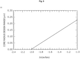
- Fig. 9 is a diagram illustrating the ⁇ dependency of a designable range of the core radius.
- the MFD is set to 9.5 um
- the designable range of the core radius is a core radius designable range with a largest ⁇ 2 / ⁇ 1 .
- the core radius designable range decreases, and the design range disappears at -2.0 ns/km (0 ⁇ m).
- ⁇ 2 / ⁇ 1 K 3 + 7.7 a 1
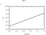
- Fig. 10 is a diagram illustrating the ⁇ dependency of K 3 in -2.0 ns/km ⁇ ⁇ ⁇ -1.0 ns/km when the MFD is 9.5 um.
- K 3 satisfies the following relationship.
- Mathematical Expression 21 for a 1 the smallest designable a 1 for ⁇ 2 / ⁇ 1 is presented, and by substituting Mathematical Expression 24 into Mathematical Expression 23 and solving Mathematical Expression 23 for a 1 , the largest designable a 2 for ⁇ 2 / ⁇ 1 is presented.
- the W-type optical fiber having the pure quartz core satisfying the relationship of [Mathematical Expression 25] 6.50 ⁇ 3.33 ⁇ 2 / ⁇ 1 ⁇ a 2 ⁇ 0.13 ⁇ 2 / ⁇ 1 ⁇ 0.22 ⁇ ⁇ 3.74 has optical properties suitable for the long-distance transmission line, and can achieve a group delay time reduction of ⁇ or less with respect to the slave channel corresponding to the general-purpose cut-off shift fiber.
- a W-type pure quartz core fiber satisfying Mathematical Expression 25 can achieve MS-CPE using the low delay signal in the long-distance transmission line including the submarine optical communication system exceeding 1000 km.
- the slave channel is the SI-type optical fiber will be described, but the slave channel may be other than the SI-type optical fiber.
- the "W-type pure quartz core fiber” means the optical fiber used for the master channel
- the "cut-off shift fiber” means the optical fiber used for the slave channel.
- the "W-type pure quartz core fiber” means the core used for the master channel
- the "cut-off shift fiber” means the core used for the slave channel.
- MFD 9.8 ⁇ m.
- the structure in which ⁇ b is 2.0 dB/100 tuns or less is a structure in which a 1 is larger than the dashed line in the drawing, and a structure in which ⁇ is 1.0 ns/km or more is a structure in which a 1 is smaller than the solid line in the drawing.
- the structure in which ⁇ b is 2.0 dB/100 tuns or less and ⁇ is 1.0 ns/km or more is the gray region in the drawing.
- Fig. 12 is a diagram illustrating the ⁇ dependency of the designable range of the core radius.
- the MFD is set to 9.8 um
- the designable range of the core radius is the core radius designable range with the largest ⁇ 2 / ⁇ 1 .
- the designable range of the core radius decreases, and the design range disappears (becomes 0 ⁇ m) at -1.46 ns/km.
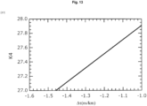
- K 4 satisfies the following relationship.
- the W-type optical fiber having the pure quartz core satisfying the relationship of [Mathematical Expression 30] 6.70 ⁇ 3.33 ⁇ 2 / ⁇ 1 ⁇ a 1 ⁇ 0.13 ⁇ 2 / ⁇ 1 ⁇ 0.26 ⁇ ⁇ 3.88 has optical properties suitable for the long-distance transmission line, and can achieve the group delay time reduction of ⁇ or less with respect to the slave channel corresponding to the general-purpose cut-off shift fiber.
- the W-type pure quartz core fiber satisfying Mathematical Expression 30 can achieve MS-CPE using the low delay signal in the long-distance transmission line including the submarine optical communication system exceeding 1000 km.
- the slave channel is the SI-type optical fiber will be described, but the slave channel may be other than the SI-type optical fiber.
- the "W-type pure quartz core fiber” means the optical fiber used for the master channel
- the "cut-off shift fiber” means the optical fiber used for the slave channel.
- the "W-type pure quartz core fiber” means the core used for the master channel
- the "cut-off shift fiber” means the core used for the slave channel.
- MFD 10.0 um.
- the structure in which ⁇ b is 2.0 dB/100 tuns or less is a structure in which a 1 is larger than the dashed line in the drawing, and a structure in which ⁇ is 1.0 ns/km or more is a structure in which a 1 is smaller than the solid line in the drawing.
- the structure in which ⁇ b is 2.0 dB/100 tuns or less and ⁇ is 1.0 ns/km or more is the gray region in the drawing.
- Fig. 12 is a diagram illustrating the ⁇ dependency of the designable range of the core radius.
- the MFD is set to 10.0 um
- the designable range of the core radius is the core radius designable range with the largest ⁇ 2 / ⁇ 1 .
- the designable range of the core radius decreases, and the design range disappears at -1.14 ns/km (0 ⁇ m).
- ⁇ 2 / ⁇ 1 K 5 + 7.7 a
- Fig. 16 is a diagram illustrating the ⁇ dependency of K 5 in -1.14 ns/km ⁇ ⁇ ⁇ -1.0 ns/km when the MFD is 10.0 um.
- K 5 satisfies the following relationship.
- Mathematical Expression 31 for a 1 the smallest designable a 1 for ⁇ 2 / ⁇ 1 is presented, and by substituting Mathematical Expression 34 into Mathematical Expression 33 and solving Mathematical Expression 33 for a 1 , the largest designable a 1 for ⁇ 2 / ⁇ 1 is presented.
- the W-type optical fiber having the pure quartz core satisfying the relationship of [Mathematical Expression 35] 6.83 ⁇ 3.33 ⁇ 2 / ⁇ 1 ⁇ a 1 ⁇ 0.13 ⁇ 2 / ⁇ 1 ⁇ 0.29 ⁇ ⁇ 3.94 has optical properties suitable for the long-distance transmission line, and can achieve the group delay time reduction of ⁇ or less with respect to the slave channel corresponding to the general-purpose cut-off shift fiber.
- the W-type pure quartz core fiber satisfying Mathematical Expression 35 can achieve MS-CPE using the low delay signal in the long-distance transmission line including the submarine optical communication system exceeding 1000 km.
- the slave channel is the SI-type optical fiber will be described, but the slave channel may be other than the SI-type optical fiber.
- the "W-type pure quartz core fiber” means the optical fiber used for the master channel
- the "cut-off shift fiber” means the optical fiber used for the slave channel.
- the "W-type pure quartz core fiber” means the core used for the master channel
- the "cut-off shift fiber” means the core used for the slave channel.
- Fig. 17 is a diagram illustrating MFD dependency of the designable range of the core radius a 1 .
- the designable range of the core radius decreases.
- the MFD can be designed to be 9.5 um or more and 10.1 um or less.
- a 1 K 6 ⁇ 0.33 ⁇ 2 / ⁇ 1 using a coefficient K 6 depending on the MFD.
- Fig. 19 is a diagram illustrating the MFD dependency of K 7 .
- Fig. 20 is a diagram illustrating the MFD dependency of K 8 .
- the W-type optical fiber having the pure quartz core satisfying the relationship of [Mathematical Expression 41] 0.23 + 0.66 MFD ⁇ 3.33 ⁇ 2 / ⁇ 1 ⁇ a 1 ⁇ 0.13 ⁇ 2 / ⁇ 1 + 1.11 ⁇ 0.14 MFD ⁇ + 0.10 ⁇ 0.41 MFD when the MFD is 9.5 um to 10.1 um has optical properties suitable for the long-distance transmission line, and can achieve the group delay time reduction of ⁇ or less with respect to the slave channel corresponding to the general-purpose cut-off shift fiber.
- the W-type pure quartz core fiber satisfying Mathematical Expression 35 can achieve MS-CPE using the low delay signal in the long-distance transmission line including the submarine optical communication system exceeding 1000 km.
- the slave channel is the SI-type optical fiber will be described, but the slave channel may be other than the SI-type optical fiber.
- the "W-type pure quartz core fiber” means the optical fiber used for the master channel
- the "cut-off shift fiber” means the optical fiber used for the slave channel.
- the "W-type pure quartz core fiber” means the core used for the master channel
- the "cut-off shift fiber” means the core used for the slave channel.
- the optical communication system of the present embodiment is characterized in that the refractive index of the core of the optical fiber of the optical transmission line 50 is lower than that of the pure silica glass.
- the structural conditions of the optical fiber having the pure silica glass as a core have been described.
- fluorine-doped glass may be used as a core.
- a larger ⁇ can be achieved by decreasing the core refractive index, and the application region of the MS-CPE using the low delay signal can be expanded.
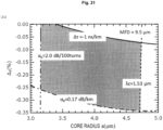
- Fig. 21 is a diagram illustrating properties (the radius a and a relative refractive index difference ⁇ F ) required for the core of the master channel.
- the relative refractive index difference ⁇ F is a relative refractive index difference of a fluorine-doped core with respect to the pure silica glass.
- the parameters are the group delay time difference ⁇ at a wavelength of 1.55 um, the bending loss ⁇ b at a wavelength of 1.625 ⁇ m, a cutoff wavelength ⁇ c, and a Rayleigh scattering loss ⁇ R at a wavelength of 1.55 ⁇ m.
- the relative refractive index difference of the clad with respect to the pure silica glass is adjusted so that the MFD is 9.5 ⁇ m in each structure.
- ⁇ c ⁇ 1.53 ⁇ m and ⁇ b ⁇ 2.0 dB/100 turns can be achieved. Further, ⁇ ⁇ -1.0 ns/km can be achieved in a region where ⁇ F is smaller than the solid line, and the Rayleigh scattering loss of 0.17 dB/km or less can be achieved in a region where ⁇ F is larger than the one dot chain line.
- Mathematical Expression 46 0.32 ⁇ 0.27 a + 0.03 a 2 ⁇ ⁇ F ⁇ 0.49 ⁇ 0.21 a + 0.02 a 2
- the structure of the gray region surrounded by curves illustrated in Fig. 21 can achieve the low delay master channel having optical properties suitable for the long-distance transmission line and enabling ⁇ ⁇ -1.0 ns/km.
- Fig. 22 is a diagram illustrating the ⁇ dependency of the design range of ⁇ F of the master channel.
- ⁇ F, max - ⁇ F, min is a designable range of ⁇ F depending on ⁇ .
- the design possible range of ⁇ F decreases, and the designable range disappears (becomes 0%) at -14.7 ns/km.
- ⁇ F K 9 ⁇ 0.21 a + 0.02 a 2
- Fig. 23 is a diagram illustrating the ⁇ dependency of K 9 in -14.7 ns/km ⁇ ⁇ ⁇ -1.0 ns/km when the MFD is 9.5 um.
- K 9 satisfies the following relationship.
- a fluorine-doped core fiber satisfying the relationship of [Mathematical Expression 49] 0.32 ⁇ 0.27 a + 0.03 a 2 ⁇ ⁇ F ⁇ 0.50 + 0.02 ⁇ ⁇ 0.21 a + 0.02 a 2 has optical properties suitable for the long-distance transmission line, and can achieve the group delay time reduction of ⁇ or less with respect to the slave channel corresponding to the general-purpose cut-off shift fiber.
- an SI-type fluorine-doped core fiber satisfying Mathematical Expression 49 can achieve MS-CPE using the low delay signal in the long-distance transmission line including the submarine optical communication system exceeding 1000 km.
- the slave channel is the SI-type optical fiber will be described, but the slave channel may be other than the SI-type optical fiber.
- the "SI-type fluorine-doped core fiber” means the optical fiber used for the master channel
- the "cut-off shift fiber” means the optical fiber used for the slave channel.
- the "SI-type fluorine-doped core fiber” means the core used for the master channel
- the "cut-off shift fiber” means the core used for the slave channel.
- Fig. 24 is also a diagram illustrating properties (the radius a and the relative refractive index difference ⁇ F ) required for the core of the master channel.
- the relative refractive index difference of the clad with respect to the pure silica glass is adjusted so that the MFD is 15.0 um in each structure.
- ⁇ c ⁇ 1.53 ⁇ m and ⁇ b ⁇ 2.0 dB/100 turns can be achieved. Further, ⁇ ⁇ -1.0 ns/km can be achieved in a region where ⁇ F is smaller than the solid line, and the Rayleigh scattering loss of 0.17 dB/km or less can be achieved in a region where ⁇ F is larger than the one dot chain line.
- Mathematical Expression 53 ⁇ 0.73 + 0.09 a + 0.01 a 2 ⁇ ⁇ F ⁇ 0.10 ⁇ 0.03 a + 0.13 ⁇ 10 ⁇ 2 a 2
- the structure of the gray region surrounded by the curves illustrated in Fig. 24 can achieve the low delay master channel having optical properties suitable for the long-distance transmission line and enabling ⁇ ⁇ -1.0 ns/km.
- Fig. 25 is a diagram illustrating the ⁇ dependency of the design range of ⁇ F of the master channel.
- ⁇ decreases, the design possible range of ⁇ F decreases, and the designable range disappears (becomes 0%) at -18.0 ns/km.
- ⁇ F K 10 ⁇ 0.03 a + 0.13 ⁇ 10 ⁇ 2 a 2
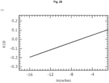
- Fig. 26 is a diagram illustrating the ⁇ dependency of K 10 in -18.0 ns/km ⁇ ⁇ ⁇ -1.0 ns/km when the MFD is 15.0 um.
- K 10 satisfies the following relationship.
- the fluorine-doped core fiber satisfying the relationship of [Mathematical Expression 56] ⁇ 0.73 + 0.09 a + 0.01 a 2 ⁇ ⁇ F ⁇ 0.13 + 0.02 ⁇ ⁇ 0.03 a + 0.13 ⁇ 10 ⁇ 2 a 2 has optical properties suitable for the long-distance transmission line, and can achieve the group delay time reduction of ⁇ or less with respect to the slave channel corresponding to the general-purpose cut-off shift fiber.
- the SI-type fluorine-doped core fiber satisfying Mathematical Expression 56 can achieve MS-CPE using the low delay signal in the long-distance transmission line including the submarine optical communication system exceeding 1000 km.
- the slave channel is the SI-type optical fiber will be described, but the slave channel may be other than the SI-type optical fiber.
- the "SI-type fluorine-doped core fiber” means the optical fiber used for the master channel
- the "cut-off shift fiber” means the optical fiber used for the slave channel.
- the "SI-type fluorine-doped core fiber” means the core used for the master channel
- the "cut-off shift fiber” means the core used for the slave channel.
- Fig. 27 is a diagram illustrating the MFD dependency of a designable minimum core radius a min in which ⁇ b is 2.0 dB/100 turns.
- the a min rises linearly with respect to the MFD.
- Fig. 28 is a diagram illustrating the MFD dependency of the designable minimum core radius a max in which ⁇ c is 1.53 um or less.
- the a max increases linearly with respect to the MFD.
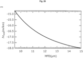
- Fig. 29 is a diagram illustrating the MFD dependency of the minimum designable ⁇ min when ⁇ b is 2.0 dB/100 turns.
- ⁇ Fmin and ⁇ Fmax with which ⁇ R is 0.17 dB/km can be expressed by the following Mathematical Expressions using coefficients K 11 , K 12 , K 13 , K 14 , K 15 , and K 16 depending on the MFD, the core radius a, and the group delay time difference ⁇ .
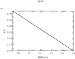
- Fig. 30 is a diagram illustrating the MFD dependency of K 11 .
- Fig. 31 is a diagram illustrating the MFD dependency of K 12 .
- Fig. 32 is a diagram illustrating the MFD dependency of K 13 .
- Fig. 33 is a diagram illustrating the MFD dependency of K 14 .
- Fig. 34 is a diagram illustrating the MFD dependency of K 15 .
- Fig. 35 is a diagram illustrating the MFD dependency of K 16 .
- the fluorine-doped core fiber satisfying the relationship of [Mathematical Expression 68] 0.98 ⁇ 0.06 MFD ⁇ 0.42 + 0.03 MFD a ⁇ 0.04 + 0.002 MFD a 2 ⁇ ⁇ F ⁇ 0.03 + 1.16 ⁇ 10 3 MFD ⁇ 3.47 + 0.02 ⁇ ⁇ 0.01 + 1.88 ⁇ 10 5 MFD ⁇ 5.09 a + 0.64 ⁇ 10 ⁇ 3 + 1.89 ⁇ 10 4 MFD ⁇ 7.16 a 2 has optical properties suitable for the long-distance transmission line, and can achieve the group delay time reduction of ⁇ or
- the SI-type fluorine-doped core fiber satisfying Mathematical Expression 68 can achieve MS-CPE using the low delay signal in the long-distance transmission line including the submarine optical communication system exceeding 1000 km.
- designing as the W type is possible by adding a jacket having a refractive index lower than that of the core region and higher than that of a clad region so as to surround the structure of the present example.
- the slave channel is the SI-type optical fiber will be described, but the slave channel may be other than the SI-type optical fiber.
- the "SI-type fluorine-doped core fiber” means the optical fiber used for the master channel
- the "cut-off shift fiber” means the optical fiber used for the slave channel.
- the "SI-type fluorine-doped core fiber” means the core used for the master channel
- the "cut-off shift fiber” means the core used for the slave channel.
- a fluorine-doped core SI optical fiber capable of expanding an application region of MS-CPE using the low delay signal to a land relay system.
- a transmission path length of about several 100 km is assumed in the land relay system, and thus it is desirable that ⁇ be -3.4 ns/km or less from Fig. 1 .
- ⁇ b is desirably 0.1 dB/100 turns, which is equivalent to that of the general-purpose SMF.
- Fig. 36 is a diagram illustrating properties (the radius a and the relative refractive index difference ⁇ F ) required for the core of the master channel.
- the parameters are the group delay time difference ⁇ at a wavelength of 1.55 um, the bending loss ⁇ b at a wavelength of 1.625 um, the cutoff wavelength ⁇ c, and the Rayleigh scattering loss ⁇ R at a wavelength of 1.55 um.
- the relative refractive index difference of the clad with respect to the pure silica glass is adjusted so that the MFD is 9.5 um in each structure.
- ⁇ c ⁇ 1.53 ⁇ m and ⁇ b ⁇ 0.1 dB/100 turns can be achieved. Further, ⁇ ⁇ -3.4 ns/km can be achieved in a region where ⁇ F is smaller than the solid line, and the Rayleigh scattering loss of 0.17 dB/km or less can be achieved in a region where ⁇ F is larger than the one dot chain line.
- the one dot chain line is expressed by Mathematical Expression 45. That is, ⁇ ⁇ -3.4 ns/km and ⁇ R ⁇ 0.17 dB/km can be achieved in the following Mathematical Expression.
- Mathematical Expression 70 0.32 ⁇ 0.27 a + 0.03 a 2 ⁇ ⁇ F ⁇ 0.43 ⁇ 0.21 a + 0.02 a 2
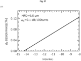
- Fig. 37 is a diagram illustrating the ⁇ dependency of the design range of ⁇ F of the master channel.
- ⁇ decreases, the design possible range of ⁇ F decreases, and the designable range disappears (becomes 0%) at -14.7 ns/km.
- Fig. 38 is a diagram illustrating properties (the radius a and the relative refractive index difference ⁇ F ) required for the core of the master channel.
- the relative refractive index difference of the clad with respect to the pure silica glass is adjusted so that the MFD is 15.0 um in each structure.
- ⁇ c ⁇ 1.53 ⁇ m and ⁇ b ⁇ 0.1 dB/100 turns can be achieved. Further, ⁇ ⁇ -3.4 ns/km can be achieved in a region where ⁇ F is smaller than the solid line, and the Rayleigh scattering loss of 0.17 dB/km or less can be achieved in a region where ⁇ F is larger than the one dot chain line.
- the one dot chain line can be expressed by Mathematical Expression 52 in the range of the core radius of Mathematical Expression 71. That is, ⁇ ⁇ -3.4 ns/km and ⁇ R ⁇ 0.17 dB/km can be achieved in the following Mathematical Expression.
- Mathematical Expression 72 ⁇ 0.73 + 0.09 a + 0.01 a 2 ⁇ ⁇ F ⁇ 0.06 ⁇ 0.03 a + 0.13 ⁇ 10 ⁇ 2 a 2
- Fig. 39 is a diagram illustrating the ⁇ dependency of the design range of ⁇ F of the master channel.
- ⁇ decreases, the design possible range of ⁇ F decreases, and the designable range disappears (becomes 0%) at -17.6 ns/km.
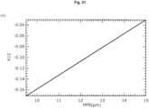
- Fig. 40 illustrates the MFD dependency of the core radius a min with ⁇ b of 0.1 dB/100 turns.
- the a min rises linearly with respect to the MFD.
- the application region of the MS-CPE using the low delay signal can be extended to about 300 km.
- designing as the W type is possible by adding a jacket having a refractive index lower than that of the core region and higher than that of the clad region so as to surround the structure of the present example.
- the multicore optical fiber according to the present embodiment includes at least one core structure described in the first to fourth embodiments.
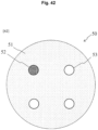
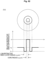
- Fig. 42 is a view illustrating a core arrangement example of the multicore optical fiber including a low delay core.
- the multicore optical fiber according to the present example two or more transmission cores (52, 53) are arranged on a square lattice in a clad 51. Then, it is characterized in that at least one (core 52) of the transmission cores is the low delay core having the structure described in the first to fourth embodiments.
- the core 52 is set as the low delay master channel, and the other cores 53 are set as the slave channels.
- MS-CPE using the low delay channel can be stably operated in the optical communication system 300.
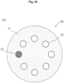
- Fig. 43 is a view illustrating a core arrangement example of the multicore optical fiber including the low delay core.
- the two or more transmission cores (52, 53) are annularly arranged in the clad 51. Then, it is characterized in that at least one (core 52) of the transmission cores is the low delay core having the structure described in the first to fourth embodiments.
- the core 52 is set as the low delay master channel, and the other cores 53 are set as the slave channels.
- Fig. 44 is a view illustrating a core arrangement example of the multicore optical fiber including the low delay core.
- the two or more transmission cores (52, 53) are arranged in the clad 51 in a hexagonal close-packed structure. Then, it is characterized in that at least one (core 52) of the transmission cores is the low delay core having the structure described in the first to fourth embodiments.
- the core 52 is set as the low delay master channel, and the other cores 53 are set as the slave channels.
- Fig. 45 is a view illustrating a core arrangement example of the multicore optical fiber including the low delay core.
- the multicore optical fiber according to the present example is characterized in that the transmission core (core 52) described in the first to fourth embodiments is arranged at the center of the clad 51, and two or more transmission cores 53 are arranged in a square lattice pattern around the transmission core in the clad 51.
- the core 52 is set as the low delay master channel, and the other cores 53 are set as the slave channels.
- MS-CPE using the low delay channel can be stably operated in the optical communication system 300.
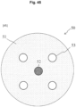
- Fig. 46 is a view illustrating a core arrangement example of the multicore optical fiber including the low delay core.
- the multicore optical fiber according to the present example is characterized in that the transmission core (core 52) described in the first to fourth embodiments is arranged at the center of the clad 51, and two or more transmission cores 53 are annularly arranged around the transmission core and in the clad 51.
- the core 52 is set as the low delay master channel, and the other cores 53 are set as the slave channels.
- MS-CPE using the low delay channel can be stably operated in the optical communication system 300.
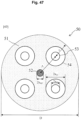
- Fig. 47 is a view illustrating a core arrangement example of the multicore optical fiber including the low delay core.
- the multicore optical fiber according to the present example is characterized in that the transmission core (core 52) described in the first to fourth embodiments is arranged at the center of the clad 51, and four transmission cores 53 are arranged in a square lattice pattern around the transmission core in the clad 51.
- the core 52 is the low delay master channel, and the cores 53 are the slave channels.
- the low delay master channel is assumed to be the SI-type, and the slave channels are assumed to be the W type including the low refractive index layer 54 on the outer periphery of the cores 53.
- the core radius of the low delay master channel is a m1
- the core radius of the slave channel is a s1
- a radius of the low refractive index layer is a s2 .
- the distance between the low delay master channel and the slave channel is ⁇ .
- Each core shares the clad 51
- the relative refractive index difference of the clad 51 with respect to the pure silica glass is ⁇ c .
- the relative refractive index difference of the low refractive index layer 54 with respect to the pure silica glass is defined as ⁇ d .
- Fig. 48 is a diagram illustrating a design region of the inter-core distance ⁇ and a refractive index difference ⁇ d of the low refractive index layer for the multicore optical fiber described in Fig. 47 .
- Fig. 48 is a calculation result of dependency of crosstalk XT m-s between the low delay master channel and the slave channels, crosstalk XT s-s between the slave channels, and the inter-core distance ⁇ and the relative refractive index difference ⁇ d of leakage loss ⁇ c in the slave channels at the wavelength of 1.625 um.
- a solid line indicates a structure in which ⁇ c is 0.01 dB/km
- a one dot chain line indicates a structure in which XT s-s is -59 dB/km
- a dashed line indicates a structure in which XT m-s is -59 dB/km.
- QPSK Quadrature phase shift keying
- a m1 and ⁇ c are 3.4 um and -0.4%, respectively, on the basis of an optical fiber structure capable of achieving MS-CPE using the low delay master channel in the optical transmission system of 1,000 km or more described in the first embodiment.
- a s1 is adjusted so that the MFD of the slave channel is 9.5 um at a wavelength of 1.55 um.
- the a s2 is set to 3a s1 on the basis of an existing cut-off shift fiber (W type). In the gray structure in the drawing, it is possible to achieve both sufficient transmission quality and sufficient low loss in the long-distance transmission line.
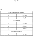
- Fig. 49 is a table for describing an example of the multicore optical fiber (MCF) structure illustrated in Fig. 47 .
- a s1 5.0 um in the cores 53 of the slave channel, and
- the inter-core distance ⁇ is 31 um. With this structure, it is possible to achieve the multicore optical fiber having sufficient low XT and low loss properties suitable for long-distance transmission illustrated in Fig. 48 .
- the group delay time of the low delay master channel is 4.879 us/km
- the group delay time of the slave channel is 4.883 us/km. This is because a group delay time difference between the low delay master channel and the slave channel is 4 ns/km, and a transmission delay time difference of 1 us or more can be achieved in an optical transmission line of 250 km or more.
- this MCF as the optical transmission line 50, it is possible to achieve the MS-CPE optical transmission system using the low delay master channel even in a distance of 250 km or more.
- the present invention is the optical communication system 301 including the optical fiber described in the first to sixth embodiments as an optical transmission line 50. That is, the optical communication system according to the present invention is as follows.
Landscapes
- Physics & Mathematics (AREA)
- General Physics & Mathematics (AREA)
- Optics & Photonics (AREA)
- Chemical & Material Sciences (AREA)
- Dispersion Chemistry (AREA)
- Optical Communication System (AREA)
- Optical Fibers, Optical Fiber Cores, And Optical Fiber Bundles (AREA)
Abstract
has a W-type refractive index distribution structure, in which a mode field diameter MFD is 9.5 to 10.1 um, and a relative refractive index difference Δ1 (%) of a low refractive index layer with respect to a core, a relative refractive index difference Δ2 (%) of the clad region with respect to the core, the core radius a1, and the group delay time difference Δτ between the Master channel and the Slave channel satisfy "Mathematical Expression 41".
Description
- The present disclosure relates to an optical fiber for optical communication.
- In a current long-distance transmission network, a dramatic increase in capacity is achieved by an optical coherent communication technology. In the optical coherent communication technology, information is allocated to a phase state of light. A phase state of signal light changes due to wavelength dispersion of an optical fiber constituting a transmission path and phase fluctuation of a signal light source, and thus signal quality deteriorates. Accordingly, in the optical coherent communication, digital signal processing (DSP) for removing phase noise in a receiver is indispensable. Although sufficient signal quality is currently ensured by the DSP, there is a problem that the calculation cost in the device increases.
- In order to solve this problem, Non
Patent Literature 1 proposes a system in which carrier phase estimation is performed using one channel in a transmission channel as a Master channel, and phase correction is performed by diverting an estimation result to other transmission channels. This transmission method is called Master-Slave CPE (MS-CPE). The MS-CPE can reduce signal processing cost for phase estimation by a Slave channel. - On the other hand, in recent optical communication, there is an increasing demand for reduction of communication delay time. According to Non
Patent Literature 2, it is reported that the DSP processing time in the optical coherent communication technology is about 1 us. Reduction of delay time of the DSP processing is also one of solutions to the request for reduction of the communication delay time. Therefore,Non Patent Literature 3 describes a possibility of reducing the DSP processing delay time in the Slave channel by applying a transmission channel with a reduced group delay time to the Master channel of the MS-CPE. -
- Non Patent Literature 1: M. D. Feuer, L. E. Nelson, X. Zhou, S. L. Woodward, R. Isaac, B. Zhu, T. F. Taunay, M. Fishteyn, J. M. Fini and M. F. Yan, "Joint Digital Signal Processing Receivers for Spatial Superchannels," Photon. Technol. Lett., vol. 24, No. 21, 1957
- Non Patent Literature 2: V. Bobrovs, S. Spolitis and G. Ivanovs, "Latency causes and reduction in optical metro networks," Proceedings in SPIE 9009, 90080C (2014)
- Non Patent Literature 3: Y. Sagae, T. Matsui, T. Sakamoto and K. Nakajima, "Multi-functional multi-core fibre based long-haul transmission system with lower DSP complexity," ECOC 2019, pp. 1-4(2019)
- The MS-CPE of
Non Patent Literature 3 uses, as an optical fiber, a multicore fiber of a core and a step-type clad in which a refractive index distribution is reduced to about 1 um for the transmission channel with the reduced group delay time. However, in the above-described core in which the refractive index distribution is reduced, the refractive index distribution is easily deformed due to a spinning tension or the like at the time of manufacturing the optical fiber (it is difficult to obtain the desired effect of MS-CPE), and there is a problem in manufacturability. - Therefore, in order to solve the above problems, an object of the present invention is to provide an optical fiber with improved manufacturability for MS-CPE.
- In order to achieve the above object, the optical fiber according to the present invention uses a low delay core using a typical refractive index distribution employed in a general-purpose optical fiber as a Master channel.
- Specifically, a first optical fiber according to the present invention is an optical fiber included in an optical communication system of an MS-CPE transmission method, characterized in that
- the optical fiber includes a core having a radius a (µm) for a master channel and a clad having a relative refractive index difference Δ (%) with respect to the core, and that
- the core and the clad have a step index (SI) type refractive index distribution structure and satisfying Mathematical Expression C1,
[Mathematical Expression C1]
- where Δτ (ns/km) is a group delay time difference between the master channel and a slave channel, and is a value that satisfies Mathematical Expression C2, where s (µs) is a signal arrival time difference when an optical signal is transmitted through the master channel and the slave channel of the optical communication system, and L (km) is a transmission distance of the optical signal.
[Mathematical Expression C2]
- Further, a second optical fiber according to the present invention is an optical fiber included in an optical communication system of an MS-CPE transmission method, characterized in that
- the optical fiber includes a core having a radius a1 (µm) for a master channel, a low refractive index layer surrounding a periphery of the core and having a relative refractive index difference Δ1 (%) with respect to the core, and a clad having a relative refractive index difference Δ2 (%) with respect to the core, and that
- the core, the low refractive index layer, and the clad have a W-type refractive index distribution structure and satisfy Mathematical Expression C3,
[Mathematical Expression C3]
- where MFD is a mode field diameter (µm) of the core, and Δτ (ns/km) is a group delay time difference between the master channel and the slave channel and is a value that satisfies Mathematical Expression C2, where s (µs) is a signal arrival time difference when an optical signal is transmitted through the master channel and the slave channel of the optical communication system, and L (km) is a transmission distance of the optical signal.
- The optical fiber according to the present invention has an effect of improving manufacturability by forming the low delay core with a general-purpose refractive index distribution structure. Therefore, the present invention can provide an optical fiber with improved manufacturability for MS-CPE.
- Further, the optical fiber according to the present invention is characterized in that the refractive index of the core is lower than that of pure silica glass. For example, the first optical fiber according to the present invention is characterized in that the radius a (um) satisfies Mathematical Expression C4, the group delay time difference Δτmin (nm/km) that is minimum satisfies Mathematical Expression C5, and a relative refractive index difference ΔF (%) of the core with respect to the pure silica glass satisfies Mathematical Expression C6.
- By reducing the refractive index of the core, a larger Δτ can be achieved, and the application region of the MS-CPE using the low delay signal can be expanded.
[Mathematical Expression C4]


- Here, the MFD is a mode field diameter (µm) of the core.
- Further, an optical fiber according to the present invention is a multicore fiber including a plurality of cores, in which one of the plurality of cores is the core for the master channel.
- Note that the respective inventions described above can be combined as much as possible.
- The present invention can provide an optical fiber with improved manufacturability for MS-CPE.
-
-
Fig. 1 is a diagram illustrating a delay reduction amount required for a transmission path length for a low delay master channel having a group delay time for achieving MS-CPE. -
Fig. 2 is a diagram illustrating a basic configuration example of an SI-type low delay master channel suitable for a submarine optical communication system. -
Fig. 3 is a diagram illustrating a designable range of a core radius for the SI-type low delay master channel suitable for the submarine optical communication system. -
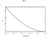
Fig. 4 is a diagram illustrating Δτ dependency of K0 for the SI-type low delay master channel suitable for the submarine optical communication system. -
Fig. 5 is a diagram illustrating the Δτ dependency of K1 for the SI-type low delay master channel suitable for the submarine optical communication system. -
Fig. 6 is a diagram illustrating the Δτ dependency of K2 for the SI-type low delay master channel suitable for the submarine optical communication system. -
Fig. 7 is a diagram illustrating an example of a design region (MFD = 9.5 um) for a W-type low delay master channel suitable for the submarine optical communication system. -
Fig. 8 is a diagram illustrating a2/a1 dependency of optical properties for the W-type low delay master channel suitable for the submarine optical communication system. -
Fig. 9 is a diagram illustrating the designable range of the core radius for the W-type low delay master channel suitable for the submarine optical communication system. -
Fig. 10 is a diagram illustrating the Δτ dependency of K3 for the W-type low delay master channel suitable for the submarine optical communication system. -
Fig. 11 is a diagram illustrating an example of a design region (MFD = 9.8 um) for the W-type low delay master channel suitable for the submarine optical communication system. -
Fig. 12 is a diagram illustrating the designable range of the core radius for the W-type low delay master channel suitable for the submarine optical communication system. -
Fig. 13 is a diagram illustrating the Δτ dependency of K4 for the W-type low delay master channel suitable for the submarine optical communication system. -
Fig. 14 is a diagram illustrating an example of a design region (MFD = 10.0 um) for the W-type low delay master channel suitable for the submarine optical communication system. -
Fig. 15 is a diagram illustrating the designable range of the core radius for the W-type low delay master channel suitable for the submarine optical communication system. -
Fig. 16 is a diagram illustrating the Δτ dependency of K5 for the W-type low delay master channel suitable for the submarine optical communication system. -
Fig. 17 is a diagram illustrating the designable range of the core radius for the W-type low delay master channel suitable for the submarine optical communication system. -
Fig. 18 is a diagram illustrating MFD dependency of K6 for the W-type low delay master channel suitable for the submarine optical communication system. -
Fig. 19 is a diagram illustrating the MFD dependency of K7 for the W-type low delay master channel suitable for the submarine optical communication system. -
Fig. 20 is a diagram illustrating the MFD dependency of K8 for the W-type low delay master channel suitable for the submarine optical communication system. -
Fig. 21 is a diagram illustrating an example of a design region (MFD = 9.5 µm) for an SI-type fluorine-doped low delay master channel suitable for the submarine optical communication system. -
Fig. 22 is a diagram illustrating a designable range of ΔF for the SI-type fluorine-doped low delay master channel suitable for the submarine optical communication system. -
Fig. 23 is a diagram illustrating the Δτ dependency of K9 for the SI-type fluorine-doped low delay master channel suitable for the submarine optical communication system. -
Fig. 24 is a diagram illustrating an example of a design region (MFD = 15.0 um) for the SI-type fluorine-doped low delay master channel suitable for the submarine optical communication system. -
Fig. 25 is a diagram illustrating the designable range of ΔF for the SI-type fluorine-doped low delay master channel suitable for the submarine optical communication system. -
Fig. 26 is a diagram illustrating the Δτ dependency of K10 for the SI-type fluorine-doped low delay master channel suitable for the submarine optical communication system. -
Fig. 27 is a diagram illustrating the MFD dependency of a designable minimum core radius for the SI-type fluorine-doped low delay master channel suitable for the submarine optical communication system. -
Fig. 28 is a diagram illustrating the MFD dependency of a designable maximum core radius for the SI-type fluorine-doped low delay master channel suitable for the submarine optical communication system. -
Fig. 29 is a diagram illustrating the MFD dependency of a designable minimum Δτ for the SI-type fluorine-doped low delay master channel suitable for the submarine optical communication system. -
Fig. 30 is a diagram illustrating the MFD dependency of K11 for the SI-type fluorine-doped low delay master channel suitable for the submarine optical communication system. -
Fig. 31 is a diagram illustrating the MFD dependency of K12 for the SI-type fluorine-doped low delay master channel suitable for the submarine optical communication system. -
Fig. 32 is a diagram illustrating the MFD dependency of K13 for the SI-type fluorine-doped low delay master channel suitable for the submarine optical communication system. -
Fig. 33 is a diagram illustrating the MFD dependency of K14 for the SI-type fluorine-doped low delay master channel suitable for the submarine optical communication system. -
Fig. 34 is a diagram illustrating the MFD dependency of K15 for the SI-type fluorine-doped low delay master channel suitable for the submarine optical communication system. -
Fig. 35 is a diagram illustrating the MFD dependency of K16 for the SI-type fluorine-doped low delay master channel suitable for the submarine optical communication system. -
Fig. 36 is a diagram illustrating an example of a design region (MFD = 9.5 um) for the SI-type fluorine-doped low delay master channel suitable for a land optical communication system. -
Fig. 37 is a diagram illustrating the designable range of ΔF for the SI-type fluorine-doped low delay master channel suitable for the land optical communication system. -
Fig. 38 is a diagram illustrating an example of a design region (MFD = 15.0 um) for the SI-type fluorine-doped low delay master channel suitable for the land optical communication system. -
Fig. 39 is a diagram illustrating the Δτ dependency of a ΔF design range for the SI-type fluorine-doped low delay master channel suitable for the land optical communication system. -
Fig. 40 is a diagram illustrating the MFD dependency of the designable minimum core radius for the SI-type fluorine-doped low delay master channel suitable for the land optical communication system. -
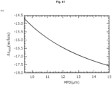
Fig. 41 is a diagram illustrating the MFD dependency of the designable minimum Δτ for the SI-type fluorine-doped low delay master channel suitable for the land optical communication system. -
Fig. 42 is a view illustrating a multicore optical fiber according to the present invention. -
Fig. 43 is a view illustrating the multicore optical fiber according to the present invention. -
Fig. 44 is a view illustrating the multicore optical fiber according to the present invention. -
Fig. 45 is a view illustrating the multicore optical fiber according to the present invention. -
Fig. 46 is a view illustrating the multicore optical fiber according to the present invention. -
Fig. 47 is a view illustrating the multicore optical fiber according to the present invention. -
Fig. 48 is a diagram illustrating a design region of an inter-core distance and a refractive index difference of a low refractive index layer of the multicore optical fiber according to the present invention. -
Fig. 49 is a diagram illustrating an example of a structure of the multicore optical fiber according to the present invention. -
Fig. 50 is a diagram illustrating an optical communication system using the optical fiber according to the present invention as an optical transmission line. -
Fig. 51 is a diagram illustrating a refractive index distribution of an SI-type optical fiber. -
Fig. 52 is a diagram illustrating a refractive index distribution of a W-type optical fiber. -
Fig. 53 is a flowchart illustrating a method for designing the optical fiber according to the present invention. - Embodiments of the present invention will be described with reference to the accompanying drawings. The embodiments described below are examples of the present invention, and the present invention is not limited to the following embodiments. Note that components having the same reference numerals in the present description and the drawings indicate the same components.
-
Fig. 50 is a diagram illustrating anoptical communication system 301 employing the MS-CPE transmission method. Theoptical communication system 301 includes atransmitter 11, areceiver 12, and anoptical transmission line 50. Theoptical transmission line 50 is an optical cable including a single core optical fiber, a multicore optical fiber, an optical fiber ribbon in which a plurality of optical fibers (single mode) is arranged in parallel, or a plurality of optical fibers (single mode). In a case of the multicore optical fiber, one of the cores is a Master channel, and the other cores are Slave channels. In a case of the optical fiber ribbon and the optical cable, one of the optical fibers is the Master channel, and the other optical fibers are the Slave channels. In a case of the single core optical fiber, an arbitrary wavelength is the Master channel, and other wavelengths are the Slave channels. - It is known that the DSP processing time reaches about 1 µs. In order to effectively reduce the DSP processing time of the Slave channels by using the MS-CPE that uses the low delay signal disclosed in
Non Patent Literature 3, it is desirable to set a signal arrival time difference between the low delay Master channel and the Slave channels in the receiver to 1 µs or more. Accordingly, when a signal arrival time difference between the Master and the Slave in the receiver is s (us), a low delay Master channel group delay time τm (µs/km), a group delay time τs (µs/km) of the Slave channel, and a transmission system length (transmission path length) L (km), a requirement of τm is determined by Mathematical Expression (10).
[Mathematical Expression 10]
- If a group delay time difference between the slave channel and the master channel is Δτ (ns/km), Mathematical Expression (10) is expressed as follows.
[Mathematical Expression 11]
-
Fig. 1 is a diagram illustrating a calculation result of L dependency of Δτ when s = 1 µs. It is possible to achieve MS-CPE using the low delay signal in a region having a smaller group delay time difference than the straight line in the drawing, that is, a lower region of the straight line. Here, Δτ is required to be -1.0 ns/km or less in a submarine optical communication system of 1000 km or more, and Δτ is required to be -3.4 ns/km or less in a land relay system of about 300 km or more. - In the present embodiment, a method of designing a core that achieves a low delay master channel in an optical fiber having an SI-type refractive index distribution structure suitable for the submarine optical communication system will be described. Here, the optical fiber is the
optical transmission line 50 inFig. 50 , and the "core" refers to only one core in a case of the single core optical fiber, refers to any one core in a case of the multicore fiber, and refers to a core of any optical fiber included in a case of the optical fiber ribbon or the optical fiber cable. The SI type is a step index type refractive index distribution structure inFig. 51 . AlthoughFig. 51 illustrates the single core optical fiber, in a case of the multicore fiber, a similar refractive index distribution structure is included for each core. -
Fig. 2 is a diagram illustrating properties (the radius a and the relative refractive index difference Δ) required for the core of the master channel. The core is the pure silica glass and has a step index type (SI type) refractive index distribution. - Parameters are a bending loss (αb), a mode field diameter (MFD), and Δτ when a channel (group delay time τs = 4.88 us/km) having properties equivalent to those of a general-purpose cut-off shift fiber (ITU-TG.654) is assumed for the slave channel. These are calculation results of the bending loss αb and the MFD at a wavelength of 1.625 um. A dashed line and a one dot chain line are boundary lines of a structure that achieves a typical bending loss recommendation value of 2.0 dB/100 tuns or less and the MFD of 9.5 um or more in the international standard ITU-T G.654 for a long-distance transmission fiber. The structure of the grey region enclosed by these curves has optical properties suitable for a long-distance transmission line and enables Δτ < -1.0 ns/km for general purpose cut-off shift fibers. In the present embodiment, a case where the slave channel is an SI-type optical fiber will be described, but the slave channel may be other than the SI-type optical fiber.
- Note that a core structure in which αb is 2.0 dB/100 turns is expressed by
[Mathematical Expression 12]
- a structure with MFD of 9.5 µm is expressed by
[Mathematical Expression 13]
- a structure in which the group delay time difference Δτ is -1.0 ns/km is expressed by
[Mathematical Expression 14]
-
Fig. 3 is a diagram illustrating Δτ dependency of a design range of a core radius of the master channel. In this calculation, when a core radius of the structure that achieves MFD = 9.5 um and Δτ = -1 ns/km is amax, and the core radius of the structure that achieves MFD = 9.5 µm and αb = 2.0 dB/100 turns is amin, amax - amin is set as the design range of the core radius. As can be seen fromFig. 3 , the range of a designable core radius decreases as Δτ decreases, and a designable structure disappears with Δτ = -2 ns/km. - With respect to a core structure that achieves a delay time difference of Δτ, a relational expression between Δ and a is expressed by
[Mathematical Expression 15]
- using coefficients K0, K1, and K2 that depend on Δτ. From
Fig. 4 , K0 is expressed by
[Mathematical Expression 16]
- using Δτ in the range of -2 ns/km < Δτ < -1.0 ns/km.
- Similarly, from
Fig. 5 , K1 is expressed by
[Mathematical Expression 17]
- Similarly, from
Fig. 6 , K2 is expressed by
[Mathematical Expression 18]
- From the above, an SI-type pure quartz core fiber that satisfies
[Mathematical Expression 19]
- and satisfies
[Mathematical Expression 20]
- has optical properties suitable for the long-distance transmission line, and can achieve Δτ of -2.0 ns/km or more and -1.0 ns/km or less with respect to the slave channel corresponding to a general-purpose cut-off shift fiber. Therefore, the SI-type pure quartz core fiber satisfying
Mathematical Expressions - Note that, in a case of the optical cable and the tape fiber, the "SI-type pure quartz core fiber" means an optical fiber used for the master channel, and the "cut-off shift fiber" means an optical fiber used for the slave channel. Further, in the case of the multicore optical fiber, as will be described later, the "SI-type pure quartz core fiber" means a core used for the master channel, and the "cut-off shift fiber" means a core used for the slave channel.
- In the present embodiment, a method of designing a core that achieves the low delay master channel in an optical fiber having a W-type refractive index distribution structure suitable for the submarine optical communication system will be described.
- Here, the optical fiber is the
optical transmission line 50 inFig. 50 , and the "core" refers to only one core in a case of the single core optical fiber, refers to any one core in a case of the multicore fiber, and refers to a core of any optical fiber included in a case of the optical fiber ribbon or the optical fiber cable. A W-type optical fiber is an optical fiber having a refractive index distribution structure illustrated inFig. 52 . AlthoughFig. 52 illustrates a single core optical fiber, in a case of the multicore fiber, a similar refractive index distribution structure is included for each core. - In a transmission path of several 1000 km class, an optical fiber having a W-type refractive index distribution having a low refractive index region around a core is often used. Here, considering application of the MS-CPE to the long-distance transmission line using the low delay Master channel, if a low delay channel is achieved by the W-type optical fiber, an existing manufacturing technology can be applied, which is preferable.
- A ratio of the relative refractive index difference Δ1 of a low refractive index layer to a core refractive index and the relative refractive index difference Δ2 of a clad with respect to the core refractive index is defined as Δ1/Δ2.
Fig. 7 is a diagram illustrating a calculation result of dependency of Δ1/Δ2 on a core radius a1 when the bending loss is αb = 2.0 dB/100 tuns and when the group delay time difference is Δτ = 1.0 ns/km. Here, like a general-purpose W-type optical fiber, a radius a2 of the low refractive index layer is set to 3 times a1, that is, a2 = 3a1, and Δ1 is adjusted so that MFD = 9.5 um is obtained in any structure. - A structure in which αb is 2.0 dB/100 tuns or less is a structure in which a1 is larger than the dashed line in the drawing, and a structure in which Δτ is 1.0 ns/km or more is a structure in which a1 is smaller than the solid line in the drawing. Thus, the structure in which αb is 2.0 dB/100 tuns or less and Δτ is 1.0 ns/km or more is the gray region in the drawing. Further, a structure in which αb of the dashed line is 2.0 dB/100 tuns satisfies the relationship of
[Mathematical Expression 21]
[Mathematical Expression 22]
-
Fig. 8 is a diagram illustrating a calculation result of a2/a1 dependency of Δτ and αb at a1 = 3.3, Δ2/Δ1 = 0.98, and MFD = 9.5 um. The solid line indicates the group delay time difference Δτ, and the dashed line indicates the bending loss αb. In the design region illustrated inFig. 8 , it can be said that there is no dependency on a2/a1. -
Fig. 9 is a diagram illustrating the Δτ dependency of a designable range of the core radius. The MFD is set to 9.5 um, and the designable range of the core radius is a core radius designable range with a largest Δ2/Δ1. As Δτ decreases, the core radius designable range decreases, and the design range disappears at -2.0 ns/km (0 µm). - Here, for the structure in which the group delay time difference is Δτ, the relationship between Δ2/Δ1 and the radius a1 is expressed as follows, for example.
[Mathematical Expression 23]
Fig. 10 is a diagram illustrating the Δτ dependency of K3 in -2.0 ns/km < Δτ < -1.0 ns/km when the MFD is 9.5 um. Here, K3 satisfies the following relationship.
[Mathematical Expression 24]
Mathematical Expression 21 for a1, the smallest designable a1 for Δ2/Δ1 is presented, and by substitutingMathematical Expression 24 intoMathematical Expression 23 and solvingMathematical Expression 23 for a1, the largest designable a2 for Δ2/Δ1 is presented. From the above, the W-type optical fiber having the pure quartz core satisfying the relationship of
[Mathematical Expression 25]
Mathematical Expression 25 can achieve MS-CPE using the low delay signal in the long-distance transmission line including the submarine optical communication system exceeding 1000 km. In the present embodiment, a case where the slave channel is the SI-type optical fiber will be described, but the slave channel may be other than the SI-type optical fiber. - Note that, in a case of the optical cable and the tape fiber, the "W-type pure quartz core fiber" means the optical fiber used for the master channel, and the "cut-off shift fiber" means the optical fiber used for the slave channel. Further, in the case of the multicore optical fiber, the "W-type pure quartz core fiber" means the core used for the master channel, and the "cut-off shift fiber" means the core used for the slave channel.
-
Fig. 11 is a diagram illustrating a calculation result of the dependency of Δ1/Δ2 on the core radius a1 when the bending loss is αb = 2.0 dB/100 tuns and when the group delay time difference is Δτ = 1.0 ns/km. Here, a2 = 3a1 is set as inFig. 7 . In the drawing, MFD = 9.8 µm. - The structure in which αb is 2.0 dB/100 tuns or less is a structure in which a1 is larger than the dashed line in the drawing, and a structure in which Δτ is 1.0 ns/km or more is a structure in which a1 is smaller than the solid line in the drawing. Thus, the structure in which αb is 2.0 dB/100 tuns or less and Δτ is 1.0 ns/km or more is the gray region in the drawing. Further, the structure in which αb of the dashed line is 2.0 dB/100 tuns satisfies the relationship of
[Mathematical Expression 26]
[Mathematical Expression 27]
-
Fig. 12 is a diagram illustrating the Δτ dependency of the designable range of the core radius. The MFD is set to 9.8 um, and the designable range of the core radius is the core radius designable range with the largest Δ2/Δ1. As Δτ decreases, the designable range of the core radius decreases, and the design range disappears (becomes 0 µm) at -1.46 ns/km. - Here, for the structure in which the group delay time difference is Δτ, the relationship between Δ2/Δ1 and the radius a1 is expressed as follows.
[Mathematical Expression 28]
Fig. 13 is a diagram illustrating the Δτ dependency of K4 in -1.46 ns/km < Δτ < -1.0 ns/km when the MFD is 9.8 um. Here, K4 satisfies the following relationship.
[Mathematical Expression 29]
Mathematical Expression 26 for a1, the smallest designable a1 for Δ2/Δ1 is presented, and by substitutingMathematical Expression 29 intoMathematical Expression 28 and solvingMathematical Expression 29 for a1, the largest designable a1 for Δ2/Δ1 is presented. From the above, the W-type optical fiber having the pure quartz core satisfying the relationship of
[Mathematical Expression 30]
Mathematical Expression 30 can achieve MS-CPE using the low delay signal in the long-distance transmission line including the submarine optical communication system exceeding 1000 km. In the present embodiment, a case where the slave channel is the SI-type optical fiber will be described, but the slave channel may be other than the SI-type optical fiber. - Note that, in the case of the optical cable and the tape fiber, the "W-type pure quartz core fiber" means the optical fiber used for the master channel, and the "cut-off shift fiber" means the optical fiber used for the slave channel. Further, in the case of the multicore optical fiber, the "W-type pure quartz core fiber" means the core used for the master channel, and the "cut-off shift fiber" means the core used for the slave channel.
-
Fig. 14 is a diagram illustrating a calculation result of the dependency of Δ1/Δ2 on the core radius a1 when the bending loss is αb = 2.0 dB/100 tuns and when the group delay time difference is Δτ = 1.0 ns/km. Here, a2 = 3a1 is set as inFig. 7 . In the drawing, MFD = 10.0 um. - The structure in which αb is 2.0 dB/100 tuns or less is a structure in which a1 is larger than the dashed line in the drawing, and a structure in which Δτ is 1.0 ns/km or more is a structure in which a1 is smaller than the solid line in the drawing. Thus, the structure in which αb is 2.0 dB/100 tuns or less and Δτ is 1.0 ns/km or more is the gray region in the drawing. Further, the structure in which αb of the dashed line is 2.0 dB/100 tuns satisfies the relationship of
[Mathematical Expression 31]
[Mathematical Expression 32]
-
Fig. 12 is a diagram illustrating the Δτ dependency of the designable range of the core radius. The MFD is set to 10.0 um, and the designable range of the core radius is the core radius designable range with the largest Δ2/Δ1. As Δτ decreases, the designable range of the core radius decreases, and the design range disappears at -1.14 ns/km (0 µm). - Here, for the structure in which the group delay time difference is Δτ, the relationship between Δ2/Δ1 and the radius a1 is expressed as follows.
[Mathematical Expression 33]
Fig. 16 is a diagram illustrating the Δτ dependency of K5 in -1.14 ns/km < Δτ < -1.0 ns/km when the MFD is 10.0 um. Here, K5 satisfies the following relationship.
[Mathematical Expression 34]
Mathematical Expression 31 for a1, the smallest designable a1 for Δ2/Δ1 is presented, and by substitutingMathematical Expression 34 intoMathematical Expression 33 and solvingMathematical Expression 33 for a1, the largest designable a1 for Δ2/Δ1 is presented. From the above, the W-type optical fiber having the pure quartz core satisfying the relationship of
[Mathematical Expression 35]
Mathematical Expression 35 can achieve MS-CPE using the low delay signal in the long-distance transmission line including the submarine optical communication system exceeding 1000 km. In the present embodiment, a case where the slave channel is the SI-type optical fiber will be described, but the slave channel may be other than the SI-type optical fiber. - Note that, in the case of the optical cable and the tape fiber, the "W-type pure quartz core fiber" means the optical fiber used for the master channel, and the "cut-off shift fiber" means the optical fiber used for the slave channel. Further, in the case of the multicore optical fiber, the "W-type pure quartz core fiber" means the core used for the master channel, and the "cut-off shift fiber" means the core used for the slave channel.
-
Fig. 17 is a diagram illustrating MFD dependency of the designable range of the core radius a1. Δ2/Δ1 = 1.00 is set, and in the core radius designable range, the bending loss αb is 2.0 dB/100 tuns or less and Δτ is 1.0 ns/km or more. As the MFD increases, the designable range of the core radius decreases. When the MFD is 10.1 µm, the core radius design range satisfying αb of 2.0 dB/100 tuns or less and Δτ of 1.0 ns/km or less disappears (becomes 0 um). Therefore, the MFD can be designed to be 9.5 um or more and 10.1 um or less. - Here, the design lower limit of the core radius a1 in
Mathematical Expressions
[Mathematical Expression 36]
Fig. 17 is a diagram describing the MFD dependency of K6. The dependency can be expressed by
[Mathematical Expression 37]
- Similarly, the design upper limit of the core radius a1 in
Mathematical Expressions
[Mathematical Expression 38]
Fig. 19 is a diagram illustrating the MFD dependency of K7. The dependency can be expressed by
[Mathematical Expression 39]
- Further,
Fig. 20 is a diagram illustrating the MFD dependency of K8. The dependency can be expressed by
[Mathematical Expression 40]
- From the above, the W-type optical fiber having the pure quartz core satisfying the relationship of
[Mathematical Expression 41]
Mathematical Expression 35 can achieve MS-CPE using the low delay signal in the long-distance transmission line including the submarine optical communication system exceeding 1000 km. In the present embodiment, a case where the slave channel is the SI-type optical fiber will be described, but the slave channel may be other than the SI-type optical fiber. - Note that, in the case of the optical cable and the tape fiber, the "W-type pure quartz core fiber" means the optical fiber used for the master channel, and the "cut-off shift fiber" means the optical fiber used for the slave channel. Further, in the case of the multicore optical fiber, the "W-type pure quartz core fiber" means the core used for the master channel, and the "cut-off shift fiber" means the core used for the slave channel.
- The optical communication system of the present embodiment is characterized in that the refractive index of the core of the optical fiber of the
optical transmission line 50 is lower than that of the pure silica glass. - In the first and second embodiments, the structural conditions of the optical fiber having the pure silica glass as a core have been described. In the SI-type and W-type structures illustrated in the first and second embodiments, fluorine-doped glass may be used as a core. In this case, a larger Δτ can be achieved by decreasing the core refractive index, and the application region of the MS-CPE using the low delay signal can be expanded.
- In the present embodiment, a method of designing a core that achieves the low delay master channel in the optical fiber having the SI-type refractive index distribution structure using fluorine-doped glass as a core will be described.
-
Fig. 21 is a diagram illustrating properties (the radius a and a relative refractive index difference ΔF) required for the core of the master channel. The relative refractive index difference ΔF is a relative refractive index difference of a fluorine-doped core with respect to the pure silica glass. - The parameters are the group delay time difference Δτ at a wavelength of 1.55 um, the bending loss αb at a wavelength of 1.625 µm, a cutoff wavelength λc, and a Rayleigh scattering loss αR at a wavelength of 1.55 µm. Here, the relative refractive index difference of the clad with respect to the pure silica glass is adjusted so that the MFD is 9.5 µm in each structure.
- By a one dot chain line, 0.17 dB/km equivalent to the Rayleigh scattering loss in the general-purpose SMF is indicated. When the core radius a satisfies
[Mathematical Expression 43]
- λc < 1.53 µm and αb < 2.0 dB/100 turns can be achieved. Further, Δτ < -1.0 ns/km can be achieved in a region where ΔF is smaller than the solid line, and the Rayleigh scattering loss of 0.17 dB/km or less can be achieved in a region where ΔF is larger than the one dot chain line.
- In the range of the core radius of
Mathematical Expression 43, the solid line can be expressed by the following Mathematical Expression
[Mathematical Expression 44]
[Mathematical Expression 45]
Mathematical Expression 43. That is, Δτ > 1.0 ns/km and αR < 0.17 dB/km can be achieved in the following Mathematical Expression.
[Mathematical Expression 46]
- The structure of the gray region surrounded by curves illustrated in
Fig. 21 can achieve the low delay master channel having optical properties suitable for the long-distance transmission line and enabling Δτ < -1.0 ns/km. -
Fig. 22 is a diagram illustrating the Δτ dependency of the design range of ΔF of the master channel. InFig. 21 , ΔF of the structure that achieves αR = 0.17 dB/km and αb = 2.0 dB/100 turns is ΔF, min, ΔF of the structure that achieves αb = 2.0 dB/100 turns and the delay time difference Δτ is ΔF, max, and ΔF, max - ΔF, min is a designable range of ΔF depending on Δτ. As Δτ decreases, the design possible range of ΔF decreases, and the designable range disappears (becomes 0%) at -14.7 ns/km. - Here, for the structure in which the group delay time difference is Δτ, the relationship between ΔF and the core radius a is expressed as follows.
[Mathematical Expression 47]
Fig. 23 is a diagram illustrating the Δτ dependency of K9 in -14.7 ns/km < Δτ < -1.0 ns/km when the MFD is 9.5 um. Here, K9 satisfies the following relationship.
[Mathematical Expression 48]
[Mathematical Expression 49]
Mathematical Expression 49 can achieve MS-CPE using the low delay signal in the long-distance transmission line including the submarine optical communication system exceeding 1000 km. In the present embodiment, a case where the slave channel is the SI-type optical fiber will be described, but the slave channel may be other than the SI-type optical fiber. - Note that, in a case of the optical cable and the tape fiber, the "SI-type fluorine-doped core fiber" means the optical fiber used for the master channel, and the "cut-off shift fiber" means the optical fiber used for the slave channel. Further, in the case of the multicore optical fiber, the "SI-type fluorine-doped core fiber" means the core used for the master channel, and the "cut-off shift fiber" means the core used for the slave channel.
-
Fig. 24 is also a diagram illustrating properties (the radius a and the relative refractive index difference ΔF) required for the core of the master channel. In this example, the relative refractive index difference of the clad with respect to the pure silica glass is adjusted so that the MFD is 15.0 um in each structure. - When the core radius a satisfies
[Mathematical Expression 50]
- λc < 1.53 µm and αb < 2.0 dB/100 turns can be achieved. Further, Δτ < -1.0 ns/km can be achieved in a region where ΔF is smaller than the solid line, and the Rayleigh scattering loss of 0.17 dB/km or less can be achieved in a region where ΔF is larger than the one dot chain line.
- In the range of the core radius of
Mathematical Expression 50, the solid line can be expressed by the following Mathematical Expression
[Mathematical Expression 51]
[Mathematical Expression 52]
Mathematical Expression 50. That is, Δτ < -1 ns/km and αR < 0.17 dB/km can be achieved in the following Mathematical Expression.
[Mathematical Expression 53]
- The structure of the gray region surrounded by the curves illustrated in
Fig. 24 can achieve the low delay master channel having optical properties suitable for the long-distance transmission line and enabling Δτ < -1.0 ns/km. -
Fig. 25 is a diagram illustrating the Δτ dependency of the design range of ΔF of the master channel.Fig. 25 is a diagram illustrating the Δτ dependency of the ΔF designable range at αb = 2.0 dB/100 turns in which the designable range of ΔF is the largest. As Δτ decreases, the design possible range of ΔF decreases, and the designable range disappears (becomes 0%) at -18.0 ns/km. - Here, for the structure in which the group delay time difference is Δτ, the relationship between ΔF and the core radius a is expressed as follows.
[Mathematical Expression 54]
Fig. 26 is a diagram illustrating the Δτ dependency of K10 in -18.0 ns/km < Δτ < -1.0 ns/km when the MFD is 15.0 um. Here, K10 satisfies the following relationship.
[Mathematical Expression 55]
[Mathematical Expression 56]
- Note that, in the case of the optical cable and the tape fiber, the "SI-type fluorine-doped core fiber" means the optical fiber used for the master channel, and the "cut-off shift fiber" means the optical fiber used for the slave channel. Further, in the case of the multicore optical fiber, the "SI-type fluorine-doped core fiber" means the core used for the master channel, and the "cut-off shift fiber" means the core used for the slave channel.
-
Fig. 27 is a diagram illustrating the MFD dependency of a designable minimum core radius amin in which αb is 2.0 dB/100 turns. The amin rises linearly with respect to the MFD. The solid line inFig. 27 can be expressed by the following Mathematical Expression.
[Mathematical Expression 57]
-
Fig. 28 is a diagram illustrating the MFD dependency of the designable minimum core radius amax in which λc is 1.53 um or less. The amax increases linearly with respect to the MFD. The solid line inFig. 28 can be expressed by the following Mathematical Expression.
[Mathematical Expression 58]
-
Fig. 29 is a diagram illustrating the MFD dependency of the minimum designable Δτmin when αb is 2.0 dB/100 turns. Δτmin can be expressed by the following Mathematical Expression.
[Mathematical Expression 59]
- Here, when the core radius is amin < a < amax and the group delay time difference to be designed is Δτmin < Δτ < - 1 ns/km, ΔFmin and ΔFmax with which αR is 0.17 dB/km can be expressed by the following Mathematical Expressions using coefficients K11, K12, K13, K14, K15, and K16 depending on the MFD, the core radius a, and the group delay time difference Δτ.
[Mathematical Expression 60]

-
Fig. 30 is a diagram illustrating the MFD dependency of K11. The straight line inFig. 30 can be expressed by the following Mathematical Expression using the MFD.
[Mathematical Expression 62]
-
Fig. 31 is a diagram illustrating the MFD dependency of K12. The straight line inFig. 31 can be expressed by the following Mathematical Expression using the MFD.
[Mathematical Expression 63]
-
Fig. 32 is a diagram illustrating the MFD dependency of K13. The straight line inFig. 32 can be expressed by the following Mathematical Expression using the MFD.
[Mathematical Expression 64]
-
Fig. 33 is a diagram illustrating the MFD dependency of K14. The curve inFig. 33 can be expressed by the following Mathematical Expression using the MFD.
[Mathematical Expression 65]
-
Fig. 34 is a diagram illustrating the MFD dependency of K15. The curve inFig. 34 can be expressed by the following Mathematical Expression using the MFD.
[Mathematical Expression 66]
-
Fig. 35 is a diagram illustrating the MFD dependency of K16. The curve inFig. 35 can be expressed by the following Mathematical Expression using the MFD.
[Mathematical Expression 67]
- As described above, for the MFD of 9.5 um or more and 15.0 um or less, when the core radius is in the region of amin < a < amax expressed by Mathematical Expressions 57 and 58, and the group delay time difference Δτ to be designed satisfies Δτmin < Δτ < -1 ns/km using Δτmin expressed by
Mathematical Expression 59, the fluorine-doped core fiber satisfying the relationship of
[Mathematical Expression 68]
- Note that, in the case of the optical cable and the tape fiber, the "SI-type fluorine-doped core fiber" means the optical fiber used for the master channel, and the "cut-off shift fiber" means the optical fiber used for the slave channel. Further, in the case of the multicore optical fiber, the "SI-type fluorine-doped core fiber" means the core used for the master channel, and the "cut-off shift fiber" means the core used for the slave channel.
- In the present embodiment, a fluorine-doped core SI optical fiber capable of expanding an application region of MS-CPE using the low delay signal to a land relay system will be described. A transmission path length of about several 100 km is assumed in the land relay system, and thus it is desirable that Δτ be -3.4 ns/km or less from
Fig. 1 . In addition, αb is desirably 0.1 dB/100 turns, which is equivalent to that of the general-purpose SMF. -
Fig. 36 is a diagram illustrating properties (the radius a and the relative refractive index difference ΔF) required for the core of the master channel. - The parameters are the group delay time difference Δτ at a wavelength of 1.55 um, the bending loss αb at a wavelength of 1.625 um, the cutoff wavelength λc, and the Rayleigh scattering loss αR at a wavelength of 1.55 um. Here, the relative refractive index difference of the clad with respect to the pure silica glass is adjusted so that the MFD is 9.5 um in each structure.
- When the radius a satisfies
[Mathematical Expression 69]
- λc < 1.53 µm and αb < 0.1 dB/100 turns can be achieved. Further, Δτ < -3.4 ns/km can be achieved in a region where ΔF is smaller than the solid line, and the Rayleigh scattering loss of 0.17 dB/km or less can be achieved in a region where ΔF is larger than the one dot chain line.
- The solid line is obtained by setting Δτ = -3.4 ns/km in
Mathematical Expressions Mathematical Expression 45. That is, Δτ < -3.4 ns/km and αR < 0.17 dB/km can be achieved in the following Mathematical Expression.
[Mathematical Expression 70]
-
Fig. 37 is a diagram illustrating the Δτ dependency of the design range of ΔF of the master channel.Fig. 37 is a diagram illustrating the Δτ dependency of the ΔF designable range at αb = 0.1 dB/100 turns in which the designable range of ΔF is the largest. As Δτ decreases, the design possible range of ΔF decreases, and the designable range disappears (becomes 0%) at -14.7 ns/km. -
Fig. 38 is a diagram illustrating properties (the radius a and the relative refractive index difference ΔF) required for the core of the master channel. In this drawing, the relative refractive index difference of the clad with respect to the pure silica glass is adjusted so that the MFD is 15.0 um in each structure. - When the core radius a satisfies
[Mathematical Expression 71]
- λc < 1.53 µm and αb < 0.1 dB/100 turns can be achieved. Further, Δτ < -3.4 ns/km can be achieved in a region where ΔF is smaller than the solid line, and the Rayleigh scattering loss of 0.17 dB/km or less can be achieved in a region where ΔF is larger than the one dot chain line.
- The solid line is obtained by setting Δτ = -3.4 ns/km in
Mathematical Expressions 54 and 55 using the core radius a in the range of the core radius a of Mathematical Expression 71. The one dot chain line can be expressed byMathematical Expression 52 in the range of the core radius of Mathematical Expression 71. That is, Δτ < -3.4 ns/km and αR < 0.17 dB/km can be achieved in the following Mathematical Expression.
[Mathematical Expression 72]
-
Fig. 39 is a diagram illustrating the Δτ dependency of the design range of ΔF of the master channel.Fig. 39 is a diagram illustrating the Δτ dependency of the ΔF designable range at αb = 0.1 dB/100 turns in which the designable range of ΔF is the largest. As Δτ decreases, the design possible range of ΔF decreases, and the designable range disappears (becomes 0%) at -17.6 ns/km. - Here, the core radius amax at which λc is 1.53 um or less can be expressed by Mathematical Expression 58.
Fig. 40 illustrates the MFD dependency of the core radius amin with αb of 0.1 dB/100 turns. The amin rises linearly with respect to the MFD. The solid line inFig. 40 can be expressed by the following Mathematical Expression.
[Mathematical Expression 73]
- Furthermore,
Fig. 41 is a diagram illustrating the MFD dependency of the minimum designable Δτ at αb = 0.1 dB/100 turns. At this time, Δτmin can be expressed by the following Mathematical Expression.
[Mathematical Expression 74]
- Here, when the core radius is amin < a < amax and the group delay time difference to be designed is Δτmin < Δτ < - 3.4 ns/km, ΔFmin and ΔFmax at which αR is 0.17 dB/km can be expressed by Mathematical Expression 68.
- In the structure described in the present embodiment, the application region of the MS-CPE using the low delay signal can be extended to about 300 km. In addition, designing as the W type is possible by adding a jacket having a refractive index lower than that of the core region and higher than that of the clad region so as to surround the structure of the present example.
- In the present embodiment, an optical communication system in which the
optical transmission line 50 is the multicore optical fiber will be described. The multicore optical fiber according to the present embodiment includes at least one core structure described in the first to fourth embodiments. -
Fig. 42 is a view illustrating a core arrangement example of the multicore optical fiber including a low delay core. In the multicore optical fiber according to the present example, two or more transmission cores (52, 53) are arranged on a square lattice in a clad 51. Then, it is characterized in that at least one (core 52) of the transmission cores is the low delay core having the structure described in the first to fourth embodiments. In the multicore optical fiber according to the present example, thecore 52 is set as the low delay master channel, and theother cores 53 are set as the slave channels. Thus, since noise due to disturbance is made common, MS-CPE using the low delay channel can be stably operated in the optical communication system 300. -
Fig. 43 is a view illustrating a core arrangement example of the multicore optical fiber including the low delay core. - In the multicore optical fiber according to the present example, the two or more transmission cores (52, 53) are annularly arranged in the clad 51. Then, it is characterized in that at least one (core 52) of the transmission cores is the low delay core having the structure described in the first to fourth embodiments. In the multicore fiber according to the present example, the
core 52 is set as the low delay master channel, and theother cores 53 are set as the slave channels. Thus, since noise due to disturbance is made common, MS-CPE using the low delay channel can be stably operated in the optical communication system 300. -
Fig. 44 is a view illustrating a core arrangement example of the multicore optical fiber including the low delay core. - In the multicore optical fiber according to the present example, the two or more transmission cores (52, 53) are arranged in the clad 51 in a hexagonal close-packed structure. Then, it is characterized in that at least one (core 52) of the transmission cores is the low delay core having the structure described in the first to fourth embodiments. In the multicore fiber according to the present example, the
core 52 is set as the low delay master channel, and theother cores 53 are set as the slave channels. Thus, since noise due to disturbance is made common, MS-CPE using the low delay channel can be stably operated in the optical communication system 300. -
Fig. 45 is a view illustrating a core arrangement example of the multicore optical fiber including the low delay core. - The multicore optical fiber according to the present example is characterized in that the transmission core (core 52) described in the first to fourth embodiments is arranged at the center of the clad 51, and two or
more transmission cores 53 are arranged in a square lattice pattern around the transmission core in the clad 51. In the multicore fiber according to the present example, thecore 52 is set as the low delay master channel, and theother cores 53 are set as the slave channels. Thus, since noise due to disturbance is made common, MS-CPE using the low delay channel can be stably operated in the optical communication system 300. -
Fig. 46 is a view illustrating a core arrangement example of the multicore optical fiber including the low delay core. - The multicore optical fiber according to the present example is characterized in that the transmission core (core 52) described in the first to fourth embodiments is arranged at the center of the clad 51, and two or
more transmission cores 53 are annularly arranged around the transmission core and in the clad 51. In the multicore fiber according to the present example, thecore 52 is set as the low delay master channel, and theother cores 53 are set as the slave channels. Thus, since noise due to disturbance is made common, MS-CPE using the low delay channel can be stably operated in the optical communication system 300. -
Fig. 47 is a view illustrating a core arrangement example of the multicore optical fiber including the low delay core. - The multicore optical fiber according to the present example is characterized in that the transmission core (core 52) described in the first to fourth embodiments is arranged at the center of the clad 51, and four
transmission cores 53 are arranged in a square lattice pattern around the transmission core in the clad 51. Thecore 52 is the low delay master channel, and thecores 53 are the slave channels. Here, the low delay master channel is assumed to be the SI-type, and the slave channels are assumed to be the W type including the lowrefractive index layer 54 on the outer periphery of thecores 53. The core radius of the low delay master channel is am1, the core radius of the slave channel is as1, and a radius of the low refractive index layer is as2. Further, the distance between the low delay master channel and the slave channel (the distance between the centers of thecore 52 and the core 53) is λ. Each core shares the clad 51, and the relative refractive index difference of the clad 51 with respect to the pure silica glass is Δc. Further, the relative refractive index difference of the lowrefractive index layer 54 with respect to the pure silica glass is defined as Δd. -
Fig. 48 is a diagram illustrating a design region of the inter-core distance Λ and a refractive index difference Δd of the low refractive index layer for the multicore optical fiber described inFig. 47 . -
Fig. 48 is a calculation result of dependency of crosstalk XTm-s between the low delay master channel and the slave channels, crosstalk XTs-s between the slave channels, and the inter-core distance Λ and the relative refractive index difference Δd of leakage loss αc in the slave channels at the wavelength of 1.625 um. - A solid line indicates a structure in which αc is 0.01 dB/km, a one dot chain line indicates a structure in which XTs-s is -59 dB/km, and a dashed line indicates a structure in which XTm-s is -59 dB/km. It is known that communication of 10,000 km Quadrature phase shift keying (QPSK) modulation can be performed with sufficient transmission quality when both the crosstalk XTm-s and XTs-s are -59 dB/km. Here, am1 and Δc are 3.4 um and -0.4%, respectively, on the basis of an optical fiber structure capable of achieving MS-CPE using the low delay master channel in the optical transmission system of 1,000 km or more described in the first embodiment. Further, as1 is adjusted so that the MFD of the slave channel is 9.5 um at a wavelength of 1.55 um. The as2 is set to 3as1 on the basis of an existing cut-off shift fiber (W type). In the gray structure in the drawing, it is possible to achieve both sufficient transmission quality and sufficient low loss in the long-distance transmission line.
-
Fig. 49 is a table for describing an example of the multicore optical fiber (MCF) structure illustrated inFig. 47 . Thecore 52 of the low delay master channel is assumed to be am1 = 3.4 µm and Δc = -0.40%. as1 = 5.0 um in thecores 53 of the slave channel, and as2 = 15.0 µm and Δd = - 0.55% in the lowrefractive index layer 54. The inter-core distance Λ is 31 um. With this structure, it is possible to achieve the multicore optical fiber having sufficient low XT and low loss properties suitable for long-distance transmission illustrated inFig. 48 . - At this time, the group delay time of the low delay master channel is 4.879 us/km, and the group delay time of the slave channel is 4.883 us/km. This is because a group delay time difference between the low delay master channel and the slave channel is 4 ns/km, and a transmission delay time difference of 1 us or more can be achieved in an optical transmission line of 250 km or more.
- As described above, by using this MCF as the
optical transmission line 50, it is possible to achieve the MS-CPE optical transmission system using the low delay master channel even in a distance of 250 km or more. - The present invention is the
optical communication system 301 including the optical fiber described in the first to sixth embodiments as anoptical transmission line 50. That is, the optical communication system according to the present invention is as follows. - (1) An optical communication system of an MS-CPE transmission method including a transmitter, a receiver, and an optical transmission line connecting the transmitter and the receiver, characterized in that an optical fiber of the optical transmission line includes
- a core having a radius a (um) for a master channel and a clad having a relative refractive index difference Δ (%) with respect to the core, the core and the clad having a step index (SI) type refractive index distribution structure and satisfying Mathematical Expression C1,
[Mathematical Expression C1]
- where Δτ (ns/km) is a group delay time difference between the master channel and a slave channel, and is a value that satisfies Mathematical Expression C2, where s (µs) is a signal arrival time difference when an optical signal is transmitted through the master channel and the slave channel of the optical communication system, and L (km) is a transmission distance of the optical signal.
[Mathematical Expression C2]
- a core having a radius a (um) for a master channel and a clad having a relative refractive index difference Δ (%) with respect to the core, the core and the clad having a step index (SI) type refractive index distribution structure and satisfying Mathematical Expression C1,
- (2) An optical communication system of an MS-CPE transmission method including a transmitter, a receiver, and an optical transmission line connecting the transmitter and the receiver, characterized in that an optical fiber of the optical transmission line includes
- a core having a radius a1 (um) for a master channel, a low refractive index layer surrounding a periphery of the core and having a relative refractive index difference Δ1 (%) with respect to the core, and a clad having a relative refractive index difference Δ2 (%) with respect to the core, in which the core, the low refractive index layer, and the clad have a W-type refractive index distribution structure and satisfy Mathematical Expression C3,
[Mathematical Expression C3]
- where MFD is a mode field diameter (um) of the core, and Δτ (ns/km) is a group delay time difference between the master channel and the slave channel and is a value that satisfies Mathematical Expression C2, where s (µs) is a signal arrival time difference when an optical signal is transmitted through the master channel and the slave channel of the optical communication system, and L (km) is a transmission distance of the optical signal.
[Mathematical Expression C2]
- a core having a radius a1 (um) for a master channel, a low refractive index layer surrounding a periphery of the core and having a relative refractive index difference Δ1 (%) with respect to the core, and a clad having a relative refractive index difference Δ2 (%) with respect to the core, in which the core, the low refractive index layer, and the clad have a W-type refractive index distribution structure and satisfy Mathematical Expression C3,
- (3) In the optical fiber according to (1) and (2) above, the core has a refractive index equivalent to that of pure silica glass, but the core may be fluorine-doped glass and may have a refractive index lower than that of the pure silica glass.
- (4) The optical fiber according to (1) above is characterized in that the core has a refractive index equivalent to that of the pure silica glass, the core is fluorine-doped glass, the refractive index is lower than that of the pure silica glass,
- the radius a (um) satisfies Mathematical Expression C4,
- the group delay time difference Δτmin (nm/km) that is minimum satisfies Mathematical Expression C5, and
- a relative refractive index difference ΔF (%) of the core with respect to the pure silica glass satisfies Mathematical Expression C6,
[Mathematical Expression C4]


- where the MFD is a mode field diameter (um) of the core.
- (5) The optical fiber according to (1) to (4) above is characterized by including a plurality of cores, in which one of the plurality of cores is the core for the master channel.
Further, the present invention is also a method for designing the optical fiber described in the first to sixth embodiments. That is, a design method according to the present invention is as follows (seeFig. 53 ). - (6) A method for designing an optical fiber included in an optical communication system of an MS-CPE transmission method is characterized by including:
- calculating (step S01) a group delay time difference Δτ (ns/km) between a master channel and a slave channel, the group delay time difference Δτ (ns/km) satisfying Mathematical Expression C2 where s (µs) is a signal arrival time difference when an optical signal is transmitted through the master channel and the slave channel of the optical communication system, and L (km) is a transmission distance of the optical signal; and
- finding (step S02) a radius a (um) of a core for a master channel and a relative refractive index difference Δ (%) of a clad to the core of the optical fiber having a step index (SI) type refractive index distribution structure from Equation C1.
- (7) A method for designing an optical fiber included in an optical communication system of an MS-CPE transmission method is characterized by including:
- calculating (step S01) a group delay time difference Δτ (ns/km) between a master channel and a slave channel, the group delay time difference Δτ (ns/km) satisfying Mathematical Expression C2 where s (µs) is a signal arrival time difference when an optical signal is transmitted through the master channel and the slave channel of the optical communication system, and L (km) is a transmission distance of the optical signal; and
- finding (step S02) a radius a1 (um) of a core for the master channel, a relative refractive index difference Δ1 (%) of a low refractive index layer surrounding a periphery of the core with respect to the core, and a relative refractive index difference Δ2 (%) of a clad with respect to the core, of the optical fiber having a W-type refractive index distribution structure from Mathematical Expression C3.
- (8) The optical fiber according to (6) and (7) above is characterized in that the core has a refractive index equivalent to that of the pure silica glass, but the core is fluorine-doped glass and has a refractive index lower than that of the pure silica glass.
- (9) The optical fiber according to (6) above is characterized in that, when the core has a refractive index equivalent to that of the pure silica glass but the optical fiber is fluorine-doped glass and a refractive index of the core is lower than that of the pure silica glass,
- the radius a (um) is found so as to satisfy Mathematical Expression C4,
- the group delay time difference Δτmin (nm/km) that is minimum is determined so as to satisfy Mathematical Expression C5, and
- the relative refractive index difference ΔF (%) of the core with respect to the pure silica glass is determined so as to satisfy the Mathematical Expression C6.
- (10) The optical fiber according to (6) to (9) above is characterized in that, when having a plurality of cores, one of the plurality of cores is the core for the master channel.
-
- 11
- Transmitter
- 12
- Receiver
- 50
- Optical transmission line (optical fiber)
- 51
- Clad
- 52
- Core for master channel
- 53
- Core for slave channel
- 54
- Low refractive index layer
- 301
- Optical communication system
Claims (5)
- An optical fiber provided in an optical communication system of an MS-CPE transmission method, the optical fiber comprisinga core having a radius a (um) for a master channel and a clad having a relative refractive index difference Δ (%) with respect to the core, the core and the clad having a step index (SI) type refractive index distribution structure and satisfying Mathematical Expression C1,
[Mathematical Expression C1] where Δτ (ns/km) is a group delay time difference between the master channel and a slave channel, and is a value that satisfies Mathematical Expression C2, [Mathematical Expression C2]
 where s (µs) is a signal arrival time difference when an optical signal is transmitted through the master channel and the slave channel of the optical communication system, and L (km) is a transmission distance of the optical signal.
 - An optical fiber provided in an optical communication system of an MS-CPE transmission method, the optical fiber comprisinga core having a radius a1 (um) for a master channel, a low refractive index layer surrounding a periphery of the core and having a relative refractive index difference Δ1 (%) with respect to the core, and a clad having a relative refractive index difference Δ2 (%) with respect to the core, wherein the core, the low refractive index layer, and the clad have a W-type refractive index distribution structure and satisfy Mathematical Expression C3,
[Mathematical Expression C3] where MFD is a mode field diameter (um) of the core, and Δτ (ns/km) is a group delay time difference between the master channel and the slave channel and is a value that satisfies Mathematical Expression C2,
[Mathematical Expression C2] where s (µs) is a signal arrival time difference when an optical signal is transmitted through the master channel and the slave channel of the optical communication system, and L (km) is a transmission distance of the optical signal.
 - The optical fiber according to claim 1 or 2, wherein a refractive index of the core is lower than a refractive index of pure silica glass.
- The optical fiber according to claim 1, whereina refractive index of the core is lower than a refractive index of pure silica glass,the radius a (um) satisfies Mathematical Expression C4,the group delay time difference Δτmin (nm/km) that is minimum satisfies Mathematical Expression C5, anda relative refractive index difference ΔF (%) of the core with respect to the pure silica glass satisfies Mathematical Expression C6,
[Mathematical Expression C4]

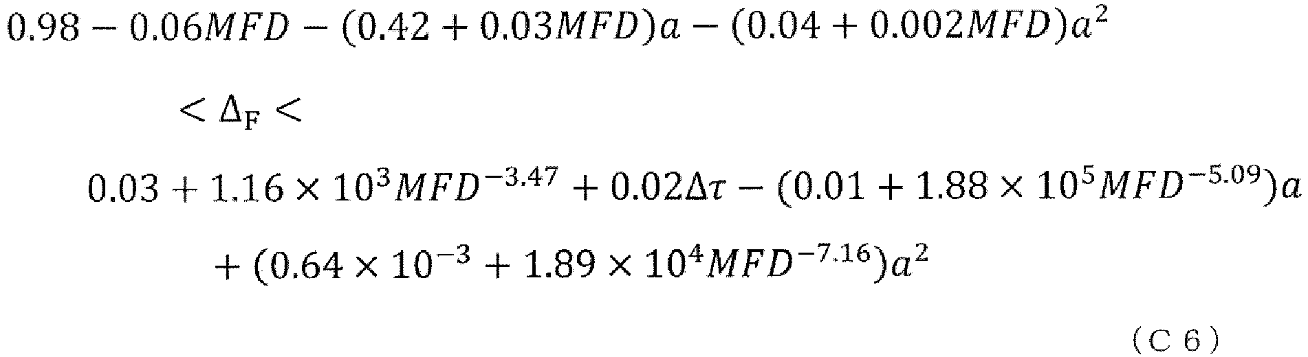
- The optical fiber according to any one of claims 1 to 4, further comprisinga plurality of cores, whereinone of the plurality of cores is the core for the master channel.
Applications Claiming Priority (1)
| Application Number | Priority Date | Filing Date | Title |
|---|---|---|---|
| PCT/JP2021/000073 WO2022149182A1 (en) | 2021-01-05 | 2021-01-05 | Optical fiber |
Publications (2)
| Publication Number | Publication Date |
|---|---|
| EP4276503A1 true EP4276503A1 (en) | 2023-11-15 |
| EP4276503A4 EP4276503A4 (en) | 2025-05-21 |
Family
ID=82358107
Family Applications (1)
| Application Number | Title | Priority Date | Filing Date |
|---|---|---|---|
| EP21917410.9A Pending EP4276503A4 (en) | 2021-01-05 | 2021-01-05 | Optical fiber |
Country Status (5)
| Country | Link |
|---|---|
| US (1) | US12498516B2 (en) |
| EP (1) | EP4276503A4 (en) |
| JP (1) | JP7533631B2 (en) |
| CN (1) | CN116710822A (en) |
| WO (1) | WO2022149182A1 (en) |
Families Citing this family (1)
| Publication number | Priority date | Publication date | Assignee | Title |
|---|---|---|---|---|
| WO2026013884A1 (en) * | 2024-07-12 | 2026-01-15 | Ntt株式会社 | Multicore optical fiber and multicore optical fiber design method |
Family Cites Families (11)
| Publication number | Priority date | Publication date | Assignee | Title |
|---|---|---|---|---|
| JP3760557B2 (en) * | 1996-04-15 | 2006-03-29 | 住友電気工業株式会社 | Dispersion compensating fiber and optical transmission system including the same |
| KR101066281B1 (en) | 2003-08-29 | 2011-09-20 | 코닝 인코포레이티드 | Optical fiber containing an alkali metal oxide, and its manufacturing method and apparatus |
| US7536076B2 (en) * | 2006-06-21 | 2009-05-19 | Corning Incorporated | Optical fiber containing alkali metal oxide |
| FR2953605B1 (en) * | 2009-12-03 | 2011-12-16 | Draka Comteq France | MULTIMODE OPTICAL FIBER WITH BROAD BANDWIDTH AND LOW BENDBACK LOSSES |
| WO2013160714A1 (en) * | 2012-04-27 | 2013-10-31 | Draka Comteq Bv | Hybrid single and multimode optical fiber for a home network |
| US9618692B2 (en) * | 2014-07-10 | 2017-04-11 | Corning Incorporated | High chlorine content low attenuation optical fiber |
| JP6623146B2 (en) * | 2016-12-02 | 2019-12-18 | 株式会社フジクラ | Method for manufacturing base material for multi-core fiber, and method for manufacturing multi-core fiber using the same |
| WO2018159146A1 (en) * | 2017-03-03 | 2018-09-07 | 住友電気工業株式会社 | Optical fiber |
| US11366266B2 (en) * | 2017-07-03 | 2022-06-21 | Nippon Telegraph And Telephone Corporation | Optical fiber and optical transmission system |
| US10591668B2 (en) * | 2017-08-08 | 2020-03-17 | Corning Incorporated | Low bend loss optical fiber with a chlorine doped core and offset trench |
| JPWO2020162406A1 (en) | 2019-02-05 | 2021-12-16 | 古河電気工業株式会社 | Optical fiber |
-
2021
- 2021-01-05 WO PCT/JP2021/000073 patent/WO2022149182A1/en not_active Ceased
- 2021-01-05 US US18/267,917 patent/US12498516B2/en active Active
- 2021-01-05 CN CN202180085812.9A patent/CN116710822A/en active Pending
- 2021-01-05 EP EP21917410.9A patent/EP4276503A4/en active Pending
- 2021-01-05 JP JP2022573813A patent/JP7533631B2/en active Active
Also Published As
| Publication number | Publication date |
|---|---|
| US12498516B2 (en) | 2025-12-16 |
| WO2022149182A1 (en) | 2022-07-14 |
| CN116710822A (en) | 2023-09-05 |
| EP4276503A4 (en) | 2025-05-21 |
| JP7533631B2 (en) | 2024-08-14 |
| US20240061168A1 (en) | 2024-02-22 |
| JPWO2022149182A1 (en) | 2022-07-14 |
Similar Documents
| Publication | Publication Date | Title |
|---|---|---|
| EP2369376B1 (en) | Multi-core optical fiber | |
| EP3913411B1 (en) | Multicore optical fiber and design method | |
| US5721800A (en) | Dispersion-shifted fiber | |
| CN103827708B (en) | Design of graded-index few-mode fiber for spatial multiplexing | |
| JP5415728B2 (en) | Multi-core holey fiber and optical transmission system | |
| EP2706387B1 (en) | Multiple LP-mode fiber designs for mode-division multiplexing | |
| US6317549B1 (en) | Optical fiber having negative dispersion and low slope in the Erbium amplifier region | |
| JPWO2000031573A1 (en) | Optical fiber and optical transmission system including the same | |
| EP2894498B1 (en) | Optical fiber | |
| CN108700703B (en) | Few-mode fiber for mode division multiplexing | |
| JP4192425B2 (en) | Optical fiber | |
| JP2007011399A (en) | Optical fiber and optical transmission system including the same | |
| US8315494B2 (en) | Optical fiber | |
| JP6611250B2 (en) | Multi-core optical fiber and multi-core optical fiber design method | |
| JPH1152161A (en) | Optical fiber | |
| WO2012108467A1 (en) | Optical fiber and optical transmission system | |
| JP2013201755A (en) | Controlling differential group delay in mode division multiplexed optical fiber systems | |
| JP5079664B2 (en) | Optical wavelength division multiplexing communication system, exciter and mode filter | |
| WO2007034923A1 (en) | Optical fiber | |
| JP2001264568A (en) | Monomode optical fiber for fiber optic transmission networks with wavelength division multiplexing | |
| US12498516B2 (en) | Optical fiber | |
| JP7731101B2 (en) | Multi-core optical fiber and optical transmission system | |
| JP6258618B2 (en) | Multi-core optical fiber | |
| CN220553007U (en) | Multi-core optical fiber and optical communication system | |
| JP2017151343A (en) | Mode scrambler and optical fiber cable |
Legal Events
| Date | Code | Title | Description |
|---|---|---|---|
| STAA | Information on the status of an ep patent application or granted ep patent |
Free format text: STATUS: THE INTERNATIONAL PUBLICATION HAS BEEN MADE |
|
| PUAI | Public reference made under article 153(3) epc to a published international application that has entered the european phase |
Free format text: ORIGINAL CODE: 0009012 |
|
| STAA | Information on the status of an ep patent application or granted ep patent |
Free format text: STATUS: REQUEST FOR EXAMINATION WAS MADE |
|
| 17P | Request for examination filed |
Effective date: 20230807 |
|
| AK | Designated contracting states |
Kind code of ref document: A1 Designated state(s): AL AT BE BG CH CY CZ DE DK EE ES FI FR GB GR HR HU IE IS IT LI LT LU LV MC MK MT NL NO PL PT RO RS SE SI SK SM TR |
|
| DAV | Request for validation of the european patent (deleted) | ||
| DAX | Request for extension of the european patent (deleted) | ||
| RIC1 | Information provided on ipc code assigned before grant |
Ipc: G02B 6/036 20060101ALI20250121BHEP Ipc: G02B 6/02 20060101AFI20250121BHEP |
|
| A4 | Supplementary search report drawn up and despatched |
Effective date: 20250417 |
|
| RIC1 | Information provided on ipc code assigned before grant |
Ipc: G02B 6/036 20060101ALI20250411BHEP Ipc: G02B 6/02 20060101AFI20250411BHEP |
|
| RAP3 | Party data changed (applicant data changed or rights of an application transferred) |
Owner name: NTT, INC. |
|
| STAA | Information on the status of an ep patent application or granted ep patent |
Free format text: STATUS: EXAMINATION IS IN PROGRESS |
|
| 17Q | First examination report despatched |
Effective date: 20260129 |