EP4276494A1 - Vehicle lane determination method, computer program product, and apparatus - Google Patents
Vehicle lane determination method, computer program product, and apparatus Download PDFInfo
- Publication number
- EP4276494A1 EP4276494A1 EP23169913.3A EP23169913A EP4276494A1 EP 4276494 A1 EP4276494 A1 EP 4276494A1 EP 23169913 A EP23169913 A EP 23169913A EP 4276494 A1 EP4276494 A1 EP 4276494A1
- Authority
- EP
- European Patent Office
- Prior art keywords
- vehicle
- lane
- determination method
- ego vehicle
- lane determination
- Prior art date
- Legal status (The legal status is an assumption and is not a legal conclusion. Google has not performed a legal analysis and makes no representation as to the accuracy of the status listed.)
- Pending
Links
Images

Classifications
-
- G—PHYSICS
- G01—MEASURING; TESTING
- G01S—RADIO DIRECTION-FINDING; RADIO NAVIGATION; DETERMINING DISTANCE OR VELOCITY BY USE OF RADIO WAVES; LOCATING OR PRESENCE-DETECTING BY USE OF THE REFLECTION OR RERADIATION OF RADIO WAVES; ANALOGOUS ARRANGEMENTS USING OTHER WAVES
- G01S13/00—Systems using the reflection or reradiation of radio waves, e.g. radar systems; Analogous systems using reflection or reradiation of waves whose nature or wavelength is irrelevant or unspecified
- G01S13/88—Radar or analogous systems specially adapted for specific applications
- G01S13/93—Radar or analogous systems specially adapted for specific applications for anti-collision purposes
- G01S13/931—Radar or analogous systems specially adapted for specific applications for anti-collision purposes of land vehicles
-
- G—PHYSICS
- G08—SIGNALLING
- G08G—TRAFFIC CONTROL SYSTEMS
- G08G1/00—Traffic control systems for road vehicles
- G08G1/20—Monitoring the location of vehicles belonging to a group, e.g. fleet of vehicles, countable or determined number of vehicles
-
- G—PHYSICS
- G01—MEASURING; TESTING
- G01C—MEASURING DISTANCES, LEVELS OR BEARINGS; SURVEYING; NAVIGATION; GYROSCOPIC INSTRUMENTS; PHOTOGRAMMETRY OR VIDEOGRAMMETRY
- G01C21/00—Navigation; Navigational instruments not provided for in groups G01C1/00 - G01C19/00
- G01C21/26—Navigation; Navigational instruments not provided for in groups G01C1/00 - G01C19/00 specially adapted for navigation in a road network
- G01C21/34—Route searching; Route guidance
- G01C21/3407—Route searching; Route guidance specially adapted for specific applications
- G01C21/343—Calculating itineraries
-
- B—PERFORMING OPERATIONS; TRANSPORTING
- B60—VEHICLES IN GENERAL
- B60W—CONJOINT CONTROL OF VEHICLE SUB-UNITS OF DIFFERENT TYPE OR DIFFERENT FUNCTION; CONTROL SYSTEMS SPECIALLY ADAPTED FOR HYBRID VEHICLES; ROAD VEHICLE DRIVE CONTROL SYSTEMS FOR PURPOSES NOT RELATED TO THE CONTROL OF A PARTICULAR SUB-UNIT
- B60W30/00—Purposes of road vehicle drive control systems not related to the control of a particular sub-unit, e.g. of systems using conjoint control of vehicle sub-units
- B60W30/10—Path keeping
- B60W30/12—Lane keeping
-
- B—PERFORMING OPERATIONS; TRANSPORTING
- B60—VEHICLES IN GENERAL
- B60W—CONJOINT CONTROL OF VEHICLE SUB-UNITS OF DIFFERENT TYPE OR DIFFERENT FUNCTION; CONTROL SYSTEMS SPECIALLY ADAPTED FOR HYBRID VEHICLES; ROAD VEHICLE DRIVE CONTROL SYSTEMS FOR PURPOSES NOT RELATED TO THE CONTROL OF A PARTICULAR SUB-UNIT
- B60W60/00—Drive control systems specially adapted for autonomous road vehicles
- B60W60/001—Planning or execution of driving tasks
-
- G—PHYSICS
- G01—MEASURING; TESTING
- G01C—MEASURING DISTANCES, LEVELS OR BEARINGS; SURVEYING; NAVIGATION; GYROSCOPIC INSTRUMENTS; PHOTOGRAMMETRY OR VIDEOGRAMMETRY
- G01C21/00—Navigation; Navigational instruments not provided for in groups G01C1/00 - G01C19/00
- G01C21/26—Navigation; Navigational instruments not provided for in groups G01C1/00 - G01C19/00 specially adapted for navigation in a road network
- G01C21/34—Route searching; Route guidance
- G01C21/3453—Special cost functions, i.e. other than distance or default speed limit of road segments
- G01C21/3492—Special cost functions, i.e. other than distance or default speed limit of road segments employing speed data or traffic data, e.g. real-time or historical
-
- G—PHYSICS
- G01—MEASURING; TESTING
- G01S—RADIO DIRECTION-FINDING; RADIO NAVIGATION; DETERMINING DISTANCE OR VELOCITY BY USE OF RADIO WAVES; LOCATING OR PRESENCE-DETECTING BY USE OF THE REFLECTION OR RERADIATION OF RADIO WAVES; ANALOGOUS ARRANGEMENTS USING OTHER WAVES
- G01S13/00—Systems using the reflection or reradiation of radio waves, e.g. radar systems; Analogous systems using reflection or reradiation of waves whose nature or wavelength is irrelevant or unspecified
- G01S13/02—Systems using reflection of radio waves, e.g. primary radar systems; Analogous systems
- G01S13/06—Systems determining position data of a target
- G01S13/42—Simultaneous measurement of distance and other co-ordinates
-
- G—PHYSICS
- G01—MEASURING; TESTING
- G01S—RADIO DIRECTION-FINDING; RADIO NAVIGATION; DETERMINING DISTANCE OR VELOCITY BY USE OF RADIO WAVES; LOCATING OR PRESENCE-DETECTING BY USE OF THE REFLECTION OR RERADIATION OF RADIO WAVES; ANALOGOUS ARRANGEMENTS USING OTHER WAVES
- G01S13/00—Systems using the reflection or reradiation of radio waves, e.g. radar systems; Analogous systems using reflection or reradiation of waves whose nature or wavelength is irrelevant or unspecified
- G01S13/66—Radar-tracking systems; Analogous systems
- G01S13/72—Radar-tracking systems; Analogous systems for two-dimensional [2D] tracking, e.g. combination of angle and range tracking, track-while-scan radar
- G01S13/723—Radar-tracking systems; Analogous systems for two-dimensional [2D] tracking, e.g. combination of angle and range tracking, track-while-scan radar by using numerical data
- G01S13/726—Multiple target tracking
-
- G—PHYSICS
- G01—MEASURING; TESTING
- G01S—RADIO DIRECTION-FINDING; RADIO NAVIGATION; DETERMINING DISTANCE OR VELOCITY BY USE OF RADIO WAVES; LOCATING OR PRESENCE-DETECTING BY USE OF THE REFLECTION OR RERADIATION OF RADIO WAVES; ANALOGOUS ARRANGEMENTS USING OTHER WAVES
- G01S19/00—Satellite radio beacon positioning systems; Determining position, velocity or attitude using signals transmitted by such systems
- G01S19/38—Determining a navigation solution using signals transmitted by a satellite radio beacon positioning system
- G01S19/39—Determining a navigation solution using signals transmitted by a satellite radio beacon positioning system the satellite radio beacon positioning system transmitting time-stamped messages, e.g. GPS [Global Positioning System], GLONASS [Global Orbiting Navigation Satellite System] or GALILEO
- G01S19/393—Trajectory determination or predictive tracking, e.g. Kalman filtering
-
- G—PHYSICS
- G01—MEASURING; TESTING
- G01S—RADIO DIRECTION-FINDING; RADIO NAVIGATION; DETERMINING DISTANCE OR VELOCITY BY USE OF RADIO WAVES; LOCATING OR PRESENCE-DETECTING BY USE OF THE REFLECTION OR RERADIATION OF RADIO WAVES; ANALOGOUS ARRANGEMENTS USING OTHER WAVES
- G01S19/00—Satellite radio beacon positioning systems; Determining position, velocity or attitude using signals transmitted by such systems
- G01S19/38—Determining a navigation solution using signals transmitted by a satellite radio beacon positioning system
- G01S19/39—Determining a navigation solution using signals transmitted by a satellite radio beacon positioning system the satellite radio beacon positioning system transmitting time-stamped messages, e.g. GPS [Global Positioning System], GLONASS [Global Orbiting Navigation Satellite System] or GALILEO
- G01S19/42—Determining position
-
- G—PHYSICS
- G01—MEASURING; TESTING
- G01S—RADIO DIRECTION-FINDING; RADIO NAVIGATION; DETERMINING DISTANCE OR VELOCITY BY USE OF RADIO WAVES; LOCATING OR PRESENCE-DETECTING BY USE OF THE REFLECTION OR RERADIATION OF RADIO WAVES; ANALOGOUS ARRANGEMENTS USING OTHER WAVES
- G01S7/00—Details of systems according to groups G01S13/00, G01S15/00, G01S17/00
- G01S7/02—Details of systems according to groups G01S13/00, G01S15/00, G01S17/00 of systems according to group G01S13/00
- G01S7/41—Details of systems according to groups G01S13/00, G01S15/00, G01S17/00 of systems according to group G01S13/00 using analysis of echo signal for target characterisation; Target signature; Target cross-section
- G01S7/415—Identification of targets based on measurements of movement associated with the target
-
- G—PHYSICS
- G06—COMPUTING OR CALCULATING; COUNTING
- G06F—ELECTRIC DIGITAL DATA PROCESSING
- G06F18/00—Pattern recognition
- G06F18/20—Analysing
- G06F18/23—Clustering techniques
-
- G—PHYSICS
- G06—COMPUTING OR CALCULATING; COUNTING
- G06V—IMAGE OR VIDEO RECOGNITION OR UNDERSTANDING
- G06V10/00—Arrangements for image or video recognition or understanding
- G06V10/70—Arrangements for image or video recognition or understanding using pattern recognition or machine learning
- G06V10/74—Image or video pattern matching; Proximity measures in feature spaces
- G06V10/75—Organisation of the matching processes, e.g. simultaneous or sequential comparisons of image or video features; Coarse-fine approaches, e.g. multi-scale approaches; using context analysis; Selection of dictionaries
- G06V10/758—Involving statistics of pixels or of feature values, e.g. histogram matching
-
- G—PHYSICS
- G06—COMPUTING OR CALCULATING; COUNTING
- G06V—IMAGE OR VIDEO RECOGNITION OR UNDERSTANDING
- G06V20/00—Scenes; Scene-specific elements
- G06V20/50—Context or environment of the image
- G06V20/56—Context or environment of the image exterior to a vehicle by using sensors mounted on the vehicle
- G06V20/588—Recognition of the road, e.g. of lane markings; Recognition of the vehicle driving pattern in relation to the road
-
- G—PHYSICS
- G08—SIGNALLING
- G08G—TRAFFIC CONTROL SYSTEMS
- G08G1/00—Traffic control systems for road vehicles
- G08G1/01—Detecting movement of traffic to be counted or controlled
- G08G1/0104—Measuring and analyzing of parameters relative to traffic conditions
- G08G1/0108—Measuring and analyzing of parameters relative to traffic conditions based on the source of data
- G08G1/0112—Measuring and analyzing of parameters relative to traffic conditions based on the source of data from the vehicle, e.g. floating car data [FCD]
-
- G—PHYSICS
- G08—SIGNALLING
- G08G—TRAFFIC CONTROL SYSTEMS
- G08G1/00—Traffic control systems for road vehicles
- G08G1/01—Detecting movement of traffic to be counted or controlled
- G08G1/0104—Measuring and analyzing of parameters relative to traffic conditions
- G08G1/0125—Traffic data processing
-
- G—PHYSICS
- G08—SIGNALLING
- G08G—TRAFFIC CONTROL SYSTEMS
- G08G1/00—Traffic control systems for road vehicles
- G08G1/01—Detecting movement of traffic to be counted or controlled
- G08G1/052—Detecting movement of traffic to be counted or controlled with provision for determining speed or overspeed
-
- G—PHYSICS
- G08—SIGNALLING
- G08G—TRAFFIC CONTROL SYSTEMS
- G08G1/00—Traffic control systems for road vehicles
- G08G1/01—Detecting movement of traffic to be counted or controlled
- G08G1/056—Detecting movement of traffic to be counted or controlled with provision for distinguishing direction of travel
-
- G—PHYSICS
- G08—SIGNALLING
- G08G—TRAFFIC CONTROL SYSTEMS
- G08G1/00—Traffic control systems for road vehicles
- G08G1/16—Anti-collision systems
- G08G1/167—Driving aids for lane monitoring, lane changing, e.g. blind spot detection
-
- B—PERFORMING OPERATIONS; TRANSPORTING
- B60—VEHICLES IN GENERAL
- B60W—CONJOINT CONTROL OF VEHICLE SUB-UNITS OF DIFFERENT TYPE OR DIFFERENT FUNCTION; CONTROL SYSTEMS SPECIALLY ADAPTED FOR HYBRID VEHICLES; ROAD VEHICLE DRIVE CONTROL SYSTEMS FOR PURPOSES NOT RELATED TO THE CONTROL OF A PARTICULAR SUB-UNIT
- B60W2420/00—Indexing codes relating to the type of sensors based on the principle of their operation
- B60W2420/40—Photo, light or radio wave sensitive means, e.g. infrared sensors
- B60W2420/408—Radar; Laser, e.g. lidar
-
- B—PERFORMING OPERATIONS; TRANSPORTING
- B60—VEHICLES IN GENERAL
- B60W—CONJOINT CONTROL OF VEHICLE SUB-UNITS OF DIFFERENT TYPE OR DIFFERENT FUNCTION; CONTROL SYSTEMS SPECIALLY ADAPTED FOR HYBRID VEHICLES; ROAD VEHICLE DRIVE CONTROL SYSTEMS FOR PURPOSES NOT RELATED TO THE CONTROL OF A PARTICULAR SUB-UNIT
- B60W2520/00—Input parameters relating to overall vehicle dynamics
- B60W2520/06—Direction of travel
-
- B—PERFORMING OPERATIONS; TRANSPORTING
- B60—VEHICLES IN GENERAL
- B60W—CONJOINT CONTROL OF VEHICLE SUB-UNITS OF DIFFERENT TYPE OR DIFFERENT FUNCTION; CONTROL SYSTEMS SPECIALLY ADAPTED FOR HYBRID VEHICLES; ROAD VEHICLE DRIVE CONTROL SYSTEMS FOR PURPOSES NOT RELATED TO THE CONTROL OF A PARTICULAR SUB-UNIT
- B60W2552/00—Input parameters relating to infrastructure
- B60W2552/53—Road markings, e.g. lane marker or crosswalk
-
- B—PERFORMING OPERATIONS; TRANSPORTING
- B60—VEHICLES IN GENERAL
- B60W—CONJOINT CONTROL OF VEHICLE SUB-UNITS OF DIFFERENT TYPE OR DIFFERENT FUNCTION; CONTROL SYSTEMS SPECIALLY ADAPTED FOR HYBRID VEHICLES; ROAD VEHICLE DRIVE CONTROL SYSTEMS FOR PURPOSES NOT RELATED TO THE CONTROL OF A PARTICULAR SUB-UNIT
- B60W2554/00—Input parameters relating to objects
- B60W2554/20—Static objects
-
- B—PERFORMING OPERATIONS; TRANSPORTING
- B60—VEHICLES IN GENERAL
- B60W—CONJOINT CONTROL OF VEHICLE SUB-UNITS OF DIFFERENT TYPE OR DIFFERENT FUNCTION; CONTROL SYSTEMS SPECIALLY ADAPTED FOR HYBRID VEHICLES; ROAD VEHICLE DRIVE CONTROL SYSTEMS FOR PURPOSES NOT RELATED TO THE CONTROL OF A PARTICULAR SUB-UNIT
- B60W2554/00—Input parameters relating to objects
- B60W2554/40—Dynamic objects, e.g. animals, windblown objects
- B60W2554/404—Characteristics
- B60W2554/4041—Position
-
- B—PERFORMING OPERATIONS; TRANSPORTING
- B60—VEHICLES IN GENERAL
- B60W—CONJOINT CONTROL OF VEHICLE SUB-UNITS OF DIFFERENT TYPE OR DIFFERENT FUNCTION; CONTROL SYSTEMS SPECIALLY ADAPTED FOR HYBRID VEHICLES; ROAD VEHICLE DRIVE CONTROL SYSTEMS FOR PURPOSES NOT RELATED TO THE CONTROL OF A PARTICULAR SUB-UNIT
- B60W2554/00—Input parameters relating to objects
- B60W2554/40—Dynamic objects, e.g. animals, windblown objects
- B60W2554/404—Characteristics
- B60W2554/4044—Direction of movement, e.g. backwards
-
- B—PERFORMING OPERATIONS; TRANSPORTING
- B60—VEHICLES IN GENERAL
- B60W—CONJOINT CONTROL OF VEHICLE SUB-UNITS OF DIFFERENT TYPE OR DIFFERENT FUNCTION; CONTROL SYSTEMS SPECIALLY ADAPTED FOR HYBRID VEHICLES; ROAD VEHICLE DRIVE CONTROL SYSTEMS FOR PURPOSES NOT RELATED TO THE CONTROL OF A PARTICULAR SUB-UNIT
- B60W2554/00—Input parameters relating to objects
- B60W2554/80—Spatial relation or speed relative to objects
- B60W2554/801—Lateral distance
-
- B—PERFORMING OPERATIONS; TRANSPORTING
- B60—VEHICLES IN GENERAL
- B60W—CONJOINT CONTROL OF VEHICLE SUB-UNITS OF DIFFERENT TYPE OR DIFFERENT FUNCTION; CONTROL SYSTEMS SPECIALLY ADAPTED FOR HYBRID VEHICLES; ROAD VEHICLE DRIVE CONTROL SYSTEMS FOR PURPOSES NOT RELATED TO THE CONTROL OF A PARTICULAR SUB-UNIT
- B60W2556/00—Input parameters relating to data
- B60W2556/20—Data confidence level
-
- B—PERFORMING OPERATIONS; TRANSPORTING
- B60—VEHICLES IN GENERAL
- B60W—CONJOINT CONTROL OF VEHICLE SUB-UNITS OF DIFFERENT TYPE OR DIFFERENT FUNCTION; CONTROL SYSTEMS SPECIALLY ADAPTED FOR HYBRID VEHICLES; ROAD VEHICLE DRIVE CONTROL SYSTEMS FOR PURPOSES NOT RELATED TO THE CONTROL OF A PARTICULAR SUB-UNIT
- B60W2556/00—Input parameters relating to data
- B60W2556/40—High definition maps
Definitions
- the present disclosure relates to a vehicle lane determination method, computer program, and processing apparatus.
- the present disclosure is particularly relevant to road lane determination methods and processing devices for use in autonomous driving systems and ADAS (advanced driver-assistance systems).
- ADAS advanced driver-assistance systems
- Modern vehicles typically include autonomous driving systems and/or ADAS. Functions within these systems often need to determine the particular road lane that the ego vehicle is currently traveling in. For example, the determined lane will have a bearing on vehicle navigation or vehicle lane centring functions. For instance, at complex highway junctions, the navigation system may need to specify to the driver which lane to drive in. Similarly, autonomous driving systems need to know which lane to follow.
- a common technique of determining the current lane involves image processing a feed from a vehicle camera to identify the lane markings on a road.
- this technique there are problems with this technique. Firstly, its reliability is reduced during bad weather conditions or at night. Equally, on multiple lane highways, it can often be difficult for the vehicle camera to see all the road lanes from the camera's fixed position on the vehicle. At the same time, other vehicles can block the camera's view of the lane markings, or markings can fade over time. In some scenarios, it can also be difficult to differentiate lanes when there are unusual road layouts, such as when emergency lanes are present, or where the lane markings are misleading.
- a vehicle lane determination method including the steps of: determining radar data acquired at an ego vehicle; extracting characteristics from the radar data associated with other vehicles, wherein the extracted characteristics comprise positional information for the other vehicles relative to the ego vehicle, and wherein the step of extracting comprises selecting a road coordinate system and the positional information comprises a representation in the selected road coordinate system; and determining the lane of the ego vehicle based on the extracted characteristics meeting a set of lane determination conditions.
- a radar-based system for lane determination, which utilises radar data containing information about surroundings and other vehicles, such as other cars, lorries, busses and motorbikes, to identify the current lane of the ego vehicle. That is, the extracted characteristics from the radar data may correspond to parameters indicating other vehicles in adjacent road lanes to the ego vehicle.
- information on the current road may be used to improve lane determination accuracy. For example, lane-splits or lane mergers, as well as the number of lanes can be used to interpret the positional information of other cars and may be independent of ego-position of the vehicle.
- the number and position of the other vehicles may be accurately used to determine the number of lanes on one or both sides of the ego vehicle's current lane and thereby allow the ego-lane to be determined. That is, positional information providing the pose (i.e. the position and orientation) of other detected vehicles can be used to determine the ego vehicle's lane.
- positional information providing the pose (i.e. the position and orientation) of other detected vehicles can be used to determine the ego vehicle's lane.
- this avoids the need for expensive repainting of road markings or the presence of guiderails on roads in order to facilitate lane position detection.
- the limitations of camera-based systems such as low reliability in poor weather or at night, are avoided.
- the radar data may also be processed in conjunction with location and standard or high definition map data to provide improved accuracy and/or plausibility determination.
- the step of extracting characteristics from the received radar data comprises identifying other vehicles moving in a same longitudinal direction to the ego vehicle. In this way, objects in radar data are identified semantically, and subsequent processing can be optimised based on the location and movement of the identified other vehicles.
- the vehicle lane determination method further includes the step of filtering out static from the radar data.
- radar data arising from stationary objects, such as objects, such as guardrails, trees, bridges, etc, on the road area may be filtered out. This filtering may be actioned before subsequent processing steps to minimise the amount of data to be processed.
- the vehicle lane determination method further includes the step of filtering out other vehicles moving in a different longitudinal direction to the ego vehicle.
- radar data associated with objects moving in the opposite direction such as vehicles in the adjacent roadway traveling in the other direction, may be filtered out.
- the positional information comprises a representation of the other vehicles in a lateral direction relative to the ego vehicle. In this way, the lateral offset of other vehicles relative to the ego vehicle may be determined.
- the selected road coordinate system is selected to account for a location of the ego vehicle.
- the vehicles' current position may be used to improve lane determination accuracy.
- the position of the ego-vehicle can be used to select the road coordinate system, such that its positional information improves lane determination.
- the location of the ego vehicle may be derived from map in combination with GNSS/positional data or other sensor measurements.
- the selected road coordinate system is selected to account for the current road characteristics. In this way, characteristics such as road layout or road curvature can be accounted for when interpreting the radar data.
- the current road characteristics may be obtained from a database or derived from vehicle sensor measurements. Accordingly, semantic information of the road (road characteristics) can be used to select the road coordinate system, such its semantic information improves lane determination and can be derived either from map in combination with GNSS/positional data or other sensor measurements.
- the extracted characteristics from the radar data further comprise at least one of the speed, heading, yaw rate, orientation, acceleration, positions, and size of the other vehicles. In this way, the determination accuracy may be improved by accounting for movement of the other vehicles.
- the step of determining the lane of the ego vehicle further comprise accounting for at least one of the speed, heading, yaw rate, orientation, acceleration and size of the ego vehicle.
- a sensed motion of the ego vehicle may be used to improve the determination, for example by identify bends in the road or other road features.
- the step of extracting characteristics includes clustering.
- clustering such as K-means clustering, may be used to process radar data for identifying other vehicles.
- the step of extracting characteristics comprises accounting for a determined minimum lateral distance between other vehicles. In this way, known characteristics about road lane spacing may be used to improve lane determination accuracy.
- the step of determining the lane of the ego vehicle comprises using data from road coordinate system. In embodiments, the step of determining the lane of the ego vehicle comprises accounting for a known number of lanes for the location of the ego vehicle determined from road data. In this way, known information/characteristics about the number of road lanes may be used to improve lane determination accuracy.
- the road data comprises a road map.
- lane data from a standard or high definition road map may be utilised to provide improved lane determination accuracy.
- the vehicle lane determination method further includes the step of verifying a plausibility for the determined lane of the ego vehicle based on at least one of: (a) a known number of lanes for the location of the ego vehicle, or (b) filtering the determined lane over time.
- a Kalman filter or extended Kalman filter (EKF) may be used to account for previous lane determination results. In this way, a confidence level may be provided for cross checking the result provided by the processed radar data.
- the step of determining the plausibility further comprises filtering out determinations having a low probability.
- a computer program product including instructions which, when the program is executed by a computer, cause the computer to carry out the steps of the above method.
- a computer program product is provided for implementing the above method.
- a non-transitory computer readable medium including instructions, which when executed by a processor, cause the processor to execute the above method.
- a non-transitory computer readable medium is provided for implementing the above method.
- a processing apparatus implementing the above method.
- a vehicle comprising: an Advanced Driver Assistance System, ADAS, for implementing one or more functions; and the above processing apparatus for inputting a determined lane of the vehicle to the ADAS for use during the one or more functions.
- ADAS Advanced Driver Assistance System
- Embodiments of the invention utilise radar detections determined from radar data moving in the same longitudinal direction as ego vehicle and reflected back from surrounding vehicles to determine the lane-number of the ego vehicle.
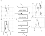
- Figure 1 is a flow diagram of a vehicle lane determination method according to a first embodiment
- Figure 2 is a schematic illustration of a processing apparatus for implementing the first embodiment.
- step 1 radar data is received at a input 101.
- each received radar detection 11 is associated with a position in the vehicle coordinate system (VCS) relative to the ego vehicle 10.
- VCS vehicle coordinate system
- the detections 11 are filtered through a filtering block 102 to remove non-relevant detections 11b associated with non-moving objects or objects moving in an opposite direction.
- a filtering block 102 receives non-relevant detections 11b from vehicles in the adjacent roadway travelling in the opposite direction.
- unwanted detections may be filtered out based on, for example, their range rate or their tracked trails, to provide a filtered output of relevant detections 11a mapped within the VCS, as shown in the insert (b) in Figure 1 .
- This filtered output is then processed through a clustering block 103, which clusters the relevant detections 11a into clusters 12 associated with objects with respect to their lateral offset within the VCS. For illustration, this is shown graphically in the insert (c) in Figure 1 .
- a K-means clustering methodology is used.
- the clustering block 103 also projects the movement of the clustered detections, and hence the associated objects, integrating in known information on the number of lanes derived from standard or high definition map data.
- the clustering block 103 may also receive yaw sensor data from within the vehicle to thereby identify bends in the roadway and account for this in the clustering process.
- the clustered data is processed by a determination block 104 for determining the lane of the ego vehicle 10.
- the detection clusters 12 are counted as neighbouring vehicles in at least one offset direction 13 (e.g. to the left of the ego vehicle). That is, the lane-number of the ego vehicle may be determined by adding one to the number of clusters identified to the left (or right) of the ego vehicle 10. For example, in the insert (d) in Figure 1 , two clusters 12 are detected, indicating the ego vehicle 10 is in the third lane. In other embodiments, the clusters in both lateral directions may be used in combination to determine the lane-number.
- the determined vehicle lane may be processed by a plausibility block 105 to filter or smooth erroneous determinations. In embodiments, this may be implemented based on the known number of lanes provided by map data.
- the plausibility block 105 may also track the lane number of the ego vehicle over time and integrate this using, for example, Markov-Models to improve the robustness of the output result 6.
- a second embodiment will now be described in relation to Figures 3 to 5 .
- This embodiment is very similar to the first embodiment and hence will only be described briefly.
- radar detections are again filtered to remove static detections and detections that are not moving in the ego direction.
- Detections 11 along a selected road coordinate system 17 are then represented onto a lateral offset direction, taking the road curvature into account.
- a road coordinate system 17 contains both semantic information and positional information about the road.
- Semantic information can be for example the type of the road (motorway, urban street, etc.), the shape of the road (straight, curve, intersection, etc.), the width of the road, the number and the width of lanes, the boundary type of the road (guardrails, curb stones, etc.), the road layout (structure of lanes like splits and merges), the road curvature and other such road characteristic information.
- the positional information can be for example lane-level information (coordinates of lanes, lane-markers and virtual centre-lines), coordinates of road boundaries, coordinates of objects like signs and many more.
- the semantic and positional information can be derived from a map (e.g.
- HD-Map or can be derived from sensor measurements.
- the road width can be determined and from the road width a maximal number of lanes can be derived.
- the shape of the road or the road curvature can be derived from sensor measurements.
- the semantic information can be seen as "coarse” information, while the positional information is effectively “fine” information with coordinates.
- the road coordinate system 17, especially the semantic attributes can be selected by selecting its type (e.g. motorway) and/or its shape (e.g. curve with specific curvature). Selection can also take into account the position of the ego-vehicle. For example, if a road coordinate system is derived from a map, the location of the vehicle is used to select the correct road coordinate system current road segment from the map and hence thus the need to be selected.
- its type e.g. motorway
- shape e.g. curve with specific curvature
- a road characteristic is a single element of the semantic information of the road coordinate system.
- the shape of the road or the road width are a characteristic.
- the selection of the road coordinate system 17 may be based on map data in combination with GNSS/positional data, as well as other sensor measurements.
- the unfiltered radar data received at input 101 may be used, at least in part, to determine the selection of the road coordinate system.
- the selected road coordinate system 17 provides information on the both the current and upcoming road curvature/shape derived, for instance, from map data and/or estimated from a detected yaw rate for the ego vehicle and other sensor data.
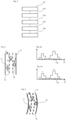
- a similar histogram of relevant radar detections 11a against lateral offset 13 may be produced, as shown in Figure 4a . It will be understood that the histogram is shown for illustration and it may not be created in practice.
- the clusters of relevant detections 11a may then be counted as shown in Figure 4(b) , taking into account the minimum spacing dictated by the lane markings 14. The lane number of the ego-vehicle may then be determined.
- a third embodiment will now be described in relation to Figures 6 and 7 .
- This embodiment is again similar to the first and second embodiments, but clusters of detections 11 are identified as objects 12.
- the driving direction of the objects 12 is then tracked, and the number of laterally offset objects is counted, again accounting for a minimum lateral spacing distance between them.
- Figure 7a three objects are detected, but as shown in Figure 7b , the clustering process identifies only two lanes are present because the two detections at position "1" are too close together to relate to separate lanes.
- the ego vehicle is then identified as being in lane three.
- a fourth embodiment will now be described in relation to Figures 8 and 9 .
- This embodiment is similar to the third embodiment, but makes use of additional information provided by a high definition map in selecting the road coordinate system 17.
- the clustering block 103 may take into account known distances between the lanes, as well as the distances between the road's guardrails/barriers 15. As shown in Figure 9(b) , this may provide more precise minimum distance parameters 16 for differentiating objects along the lateral offset.
- a radar-based system for lane determination, which utilises detections from other vehicles and objects to identify the current lane of the ego vehicle.
- characteristics from the radar data associated with other vehicles such as cluster detections, may thereby be used to determine the ego lane.
- this avoids the need for expensive repainting of road markings or the provision of guiderails.
- the limitations of camera-based systems such as low reliability in poor weather or at night, are avoided.
- the radar data may also be processed in conjunction with location and standard or high definition map data to provide improved accuracy and/or plausibility determination.
Landscapes
- Engineering & Computer Science (AREA)
- Radar, Positioning & Navigation (AREA)
- Remote Sensing (AREA)
- Physics & Mathematics (AREA)
- General Physics & Mathematics (AREA)
- Computer Networks & Wireless Communication (AREA)
- Automation & Control Theory (AREA)
- Theoretical Computer Science (AREA)
- Computer Vision & Pattern Recognition (AREA)
- Data Mining & Analysis (AREA)
- Chemical & Material Sciences (AREA)
- Analytical Chemistry (AREA)
- Electromagnetism (AREA)
- Mechanical Engineering (AREA)
- Transportation (AREA)
- Evolutionary Computation (AREA)
- Artificial Intelligence (AREA)
- Multimedia (AREA)
- Human Computer Interaction (AREA)
- Software Systems (AREA)
- Medical Informatics (AREA)
- General Health & Medical Sciences (AREA)
- Databases & Information Systems (AREA)
- Computing Systems (AREA)
- Health & Medical Sciences (AREA)
- General Engineering & Computer Science (AREA)
- Evolutionary Biology (AREA)
- Bioinformatics & Computational Biology (AREA)
- Bioinformatics & Cheminformatics (AREA)
- Life Sciences & Earth Sciences (AREA)
- Traffic Control Systems (AREA)
Abstract
Description
- The present disclosure relates to a vehicle lane determination method, computer program, and processing apparatus. The present disclosure is particularly relevant to road lane determination methods and processing devices for use in autonomous driving systems and ADAS (advanced driver-assistance systems).
- Modern vehicles typically include autonomous driving systems and/or ADAS. Functions within these systems often need to determine the particular road lane that the ego vehicle is currently traveling in. For example, the determined lane will have a bearing on vehicle navigation or vehicle lane centring functions. For instance, at complex highway junctions, the navigation system may need to specify to the driver which lane to drive in. Similarly, autonomous driving systems need to know which lane to follow.
- Conventionally, a common technique of determining the current lane involves image processing a feed from a vehicle camera to identify the lane markings on a road. However, there are problems with this technique. Firstly, its reliability is reduced during bad weather conditions or at night. Equally, on multiple lane highways, it can often be difficult for the vehicle camera to see all the road lanes from the camera's fixed position on the vehicle. At the same time, other vehicles can block the camera's view of the lane markings, or markings can fade over time. In some scenarios, it can also be difficult to differentiate lanes when there are unusual road layouts, such as when emergency lanes are present, or where the lane markings are misleading.
- A further issue arises in that higher levels of autonomous driving require a second channel, which uses a different sensor type, for plausibility checking.
- To address the above limitations, it has been suggested to use radar by repainting the lane markers with special radar reflective paint. However, this is exceptionally expensive to implement. Equally, techniques have been proposed where radar is used to determine the vehicle's distance to the road's guardrails, and this distance is used to then estimate the number of lanes in between. However, this is not always accurate, and is reliant on guardrails being present.
- Accordingly, there remains a need to address the above shortcomings in conventional vehicle lane determination systems and methods.
- According to a first aspect, there is provided a vehicle lane determination method including the steps of: determining radar data acquired at an ego vehicle; extracting characteristics from the radar data associated with other vehicles, wherein the extracted characteristics comprise positional information for the other vehicles relative to the ego vehicle, and wherein the step of extracting comprises selecting a road coordinate system and the positional information comprises a representation in the selected road coordinate system; and determining the lane of the ego vehicle based on the extracted characteristics meeting a set of lane determination conditions.
- In this way, a radar-based system is provided for lane determination, which utilises radar data containing information about surroundings and other vehicles, such as other cars, lorries, busses and motorbikes, to identify the current lane of the ego vehicle. That is, the extracted characteristics from the radar data may correspond to parameters indicating other vehicles in adjacent road lanes to the ego vehicle. At the same time, information on the current road may be used to improve lane determination accuracy. For example, lane-splits or lane mergers, as well as the number of lanes can be used to interpret the positional information of other cars and may be independent of ego-position of the vehicle. As such, the number and position of the other vehicles may be accurately used to determine the number of lanes on one or both sides of the ego vehicle's current lane and thereby allow the ego-lane to be determined. That is, positional information providing the pose (i.e. the position and orientation) of other detected vehicles can be used to determine the ego vehicle's lane. Advantageously, this avoids the need for expensive repainting of road markings or the presence of guiderails on roads in order to facilitate lane position detection. Equally, the limitations of camera-based systems, such as low reliability in poor weather or at night, are avoided. The radar data may also be processed in conjunction with location and standard or high definition map data to provide improved accuracy and/or plausibility determination.
- In embodiments, the step of extracting characteristics from the received radar data comprises identifying other vehicles moving in a same longitudinal direction to the ego vehicle. In this way, objects in radar data are identified semantically, and subsequent processing can be optimised based on the location and movement of the identified other vehicles.
- In embodiments, the vehicle lane determination method further includes the step of filtering out static from the radar data. In this way, radar data arising from stationary objects, such as objects, such as guardrails, trees, bridges, etc, on the road area, may be filtered out. This filtering may be actioned before subsequent processing steps to minimise the amount of data to be processed.
- In embodiments, the vehicle lane determination method further includes the step of filtering out other vehicles moving in a different longitudinal direction to the ego vehicle. In this way, radar data associated with objects moving in the opposite direction, such as vehicles in the adjacent roadway traveling in the other direction, may be filtered out.
- In embodiments, the positional information comprises a representation of the other vehicles in a lateral direction relative to the ego vehicle. In this way, the lateral offset of other vehicles relative to the ego vehicle may be determined.
- In embodiments, the selected road coordinate system is selected to account for a location of the ego vehicle. In this way, the vehicles' current position may be used to improve lane determination accuracy. As such, the position of the ego-vehicle can be used to select the road coordinate system, such that its positional information improves lane determination. The location of the ego vehicle may be derived from map in combination with GNSS/positional data or other sensor measurements.
- In embodiments, the selected road coordinate system is selected to account for the current road characteristics. In this way, characteristics such as road layout or road curvature can be accounted for when interpreting the radar data. In embodiments, the current road characteristics may be obtained from a database or derived from vehicle sensor measurements. Accordingly, semantic information of the road (road characteristics) can be used to select the road coordinate system, such its semantic information improves lane determination and can be derived either from map in combination with GNSS/positional data or other sensor measurements.
- In embodiments, the extracted characteristics from the radar data further comprise at least one of the speed, heading, yaw rate, orientation, acceleration, positions, and size of the other vehicles. In this way, the determination accuracy may be improved by accounting for movement of the other vehicles.
- In embodiments, the step of determining the lane of the ego vehicle further comprise accounting for at least one of the speed, heading, yaw rate, orientation, acceleration and size of the ego vehicle. In this way, a sensed motion of the ego vehicle may be used to improve the determination, for example by identify bends in the road or other road features.
- In embodiments, the step of extracting characteristics includes clustering. In this way, clustering, such as K-means clustering, may be used to process radar data for identifying other vehicles.
- In embodiments, the step of extracting characteristics comprises accounting for a determined minimum lateral distance between other vehicles. In this way, known characteristics about road lane spacing may be used to improve lane determination accuracy.
- In embodiments, the step of determining the lane of the ego vehicle comprises using data from road coordinate system. In embodiments, the step of determining the lane of the ego vehicle comprises accounting for a known number of lanes for the location of the ego vehicle determined from road data. In this way, known information/characteristics about the number of road lanes may be used to improve lane determination accuracy.
- In embodiments, the road data comprises a road map. In this way, lane data from a standard or high definition road map may be utilised to provide improved lane determination accuracy.
- In embodiments, the vehicle lane determination method further includes the step of verifying a plausibility for the determined lane of the ego vehicle based on at least one of: (a) a known number of lanes for the location of the ego vehicle, or (b) filtering the determined lane over time. For example, a Kalman filter or extended Kalman filter (EKF) may be used to account for previous lane determination results. In this way, a confidence level may be provided for cross checking the result provided by the processed radar data. In embodiments, the step of determining the plausibility further comprises filtering out determinations having a low probability.
- According to a second aspect, there is provided a computer program product including instructions which, when the program is executed by a computer, cause the computer to carry out the steps of the above method. In this way, a computer program product is provided for implementing the above method.
- According to a third aspect, there is provided a non-transitory computer readable medium including instructions, which when executed by a processor, cause the processor to execute the above method. In this way, a non-transitory computer readable medium is provided for implementing the above method.
- According to a fourth aspect, there is provided a processing apparatus implementing the above method.
- According to a fifth aspect, there is provided a vehicle comprising: an Advanced Driver Assistance System, ADAS, for implementing one or more functions; and the above processing apparatus for inputting a determined lane of the vehicle to the ADAS for use during the one or more functions.
- Illustrative embodiments will now be described with reference to the accompanying drawings in which:
-
Figure 1 is a flow diagram of a vehicle lane determination method according to a first embodiment; -
Figure 2 is a schematic illustration of a processing apparatus used for lane determination according to the first embodiment; -
Figure 3 is a schematic illustration of a vehicle lane determination method according to a second embodiment; -
Figure 4 shows illustrative histograms used in the second embodiment; -
Figure 5 is a schematic illustration of the second embodiment when applied to a curved road; -
Figure 6 is a schematic illustration of a vehicle lane determination method according to a third embodiment; -
Figure 7 shows illustrative histograms used in the third embodiment; -
Figure 8 is a schematic illustration of a vehicle lane determination method according to a fourth embodiment; and -
Figure 9 shows illustrative histograms used in the fourth embodiment. - Embodiments of the invention utilise radar detections determined from radar data moving in the same longitudinal direction as ego vehicle and reflected back from surrounding vehicles to determine the lane-number of the ego vehicle. In this respect,
Figure 1 is a flow diagram of a vehicle lane determination method according to a first embodiment, andFigure 2 is a schematic illustration of a processing apparatus for implementing the first embodiment. - In
step 1, radar data is received at ainput 101. As shown in the insert (a) inFigure 1 , each receivedradar detection 11 is associated with a position in the vehicle coordinate system (VCS) relative to theego vehicle 10. - In
step 2, thedetections 11 are filtered through afiltering block 102 to removenon-relevant detections 11b associated with non-moving objects or objects moving in an opposite direction. For example, in the insert (a) inFigure 1 , a high density ofunwanted detections 11b are received from vehicles in the adjacent roadway travelling in the opposite direction. These unwanted detections may be filtered out based on, for example, their range rate or their tracked trails, to provide a filtered output ofrelevant detections 11a mapped within the VCS, as shown in the insert (b) inFigure 1 . - This filtered output is then processed through a
clustering block 103, which clusters therelevant detections 11a intoclusters 12 associated with objects with respect to their lateral offset within the VCS. For illustration, this is shown graphically in the insert (c) inFigure 1 . In embodiments, a K-means clustering methodology is used. In this embodiment, theclustering block 103 also projects the movement of the clustered detections, and hence the associated objects, integrating in known information on the number of lanes derived from standard or high definition map data. Theclustering block 103 may also receive yaw sensor data from within the vehicle to thereby identify bends in the roadway and account for this in the clustering process. - In step 4, the clustered data is processed by a
determination block 104 for determining the lane of theego vehicle 10. For this, thedetection clusters 12 are counted as neighbouring vehicles in at least one offset direction 13 (e.g. to the left of the ego vehicle). That is, the lane-number of the ego vehicle may be determined by adding one to the number of clusters identified to the left (or right) of theego vehicle 10. For example, in the insert (d) inFigure 1 , twoclusters 12 are detected, indicating theego vehicle 10 is in the third lane. In other embodiments, the clusters in both lateral directions may be used in combination to determine the lane-number. - In step 4, the determined vehicle lane may be processed by a
plausibility block 105 to filter or smooth erroneous determinations. In embodiments, this may be implemented based on the known number of lanes provided by map data. Theplausibility block 105 may also track the lane number of the ego vehicle over time and integrate this using, for example, Markov-Models to improve the robustness of theoutput result 6. - A second embodiment will now be described in relation to
Figures 3 to 5 . This embodiment is very similar to the first embodiment and hence will only be described briefly. As shown inFigure 3 , radar detections are again filtered to remove static detections and detections that are not moving in the ego direction.Detections 11 along a selected road coordinatesystem 17 are then represented onto a lateral offset direction, taking the road curvature into account. - In this connection, a road coordinate
system 17 contains both semantic information and positional information about the road. Semantic information can be for example the type of the road (motorway, urban street, etc.), the shape of the road (straight, curve, intersection, etc.), the width of the road, the number and the width of lanes, the boundary type of the road (guardrails, curb stones, etc.), the road layout (structure of lanes like splits and merges), the road curvature and other such road characteristic information. The positional information can be for example lane-level information (coordinates of lanes, lane-markers and virtual centre-lines), coordinates of road boundaries, coordinates of objects like signs and many more. In embodiments, the semantic and positional information can be derived from a map (e.g. HD-Map) or can be derived from sensor measurements. For example by detecting the guardrails, the road width can be determined and from the road width a maximal number of lanes can be derived. Also the shape of the road or the road curvature can be derived from sensor measurements. In other words, the semantic information can be seen as "coarse" information, while the positional information is effectively "fine" information with coordinates. - The road coordinate
system 17, especially the semantic attributes can be selected by selecting its type (e.g. motorway) and/or its shape (e.g. curve with specific curvature). Selection can also take into account the position of the ego-vehicle. For example, if a road coordinate system is derived from a map, the location of the vehicle is used to select the correct road coordinate system current road segment from the map and hence thus the need to be selected. - Furthermore, a road characteristic is a single element of the semantic information of the road coordinate system. For example, the shape of the road or the road width are a characteristic.
- The selection of the road coordinate
system 17 may be based on map data in combination with GNSS/positional data, as well as other sensor measurements. For example, the unfiltered radar data received atinput 101 may be used, at least in part, to determine the selection of the road coordinate system. - Accordingly, the selected road coordinate
system 17 provides information on the both the current and upcoming road curvature/shape derived, for instance, from map data and/or estimated from a detected yaw rate for the ego vehicle and other sensor data. As such, whether the road is straight, as shown inFigure 3 , or curved, as shown inFigure 5 , a similar histogram ofrelevant radar detections 11a against lateral offset 13 may be produced, as shown inFigure 4a . It will be understood that the histogram is shown for illustration and it may not be created in practice. As described above in relation toFigure 1 , the clusters ofrelevant detections 11a may then be counted as shown inFigure 4(b) , taking into account the minimum spacing dictated by thelane markings 14. The lane number of the ego-vehicle may then be determined. - A third embodiment will now be described in relation to
Figures 6 and 7 . This embodiment is again similar to the first and second embodiments, but clusters ofdetections 11 are identified as objects 12. The driving direction of theobjects 12 is then tracked, and the number of laterally offset objects is counted, again accounting for a minimum lateral spacing distance between them. As shown inFigure 7a , three objects are detected, but as shown inFigure 7b , the clustering process identifies only two lanes are present because the two detections at position "1" are too close together to relate to separate lanes. The ego vehicle is then identified as being in lane three. - A fourth embodiment will now be described in relation to
Figures 8 and 9 . This embodiment is similar to the third embodiment, but makes use of additional information provided by a high definition map in selecting the road coordinatesystem 17. In this case, theclustering block 103 may take into account known distances between the lanes, as well as the distances between the road's guardrails/barriers 15. As shown inFigure 9(b) , this may provide more preciseminimum distance parameters 16 for differentiating objects along the lateral offset. - Accordingly, with the above arrangements, a radar-based system is provided for lane determination, which utilises detections from other vehicles and objects to identify the current lane of the ego vehicle. As such, characteristics from the radar data associated with other vehicles, such as cluster detections, may thereby be used to determine the ego lane. Advantageously, this avoids the need for expensive repainting of road markings or the provision of guiderails. Equally, the limitations of camera-based systems, such as low reliability in poor weather or at night, are avoided. The radar data may also be processed in conjunction with location and standard or high definition map data to provide improved accuracy and/or plausibility determination.
- It will be understood that the embodiments illustrated above show applications only for the purposes of illustration. In practice, embodiments may be applied to many different configurations, the detailed embodiments being straightforward for those skilled in the art to implement.
- For example, it will be understood that, whilst the apparatus described in
Figure 2 shows a plurality of separate blocks, these processing functions may be implemented using one or more microprocessors, such as within a vehicle electronic control unit (ECU).
Claims (14)
- A vehicle lane determination method comprising the steps of:determining radar data acquired at an ego vehicle;extracting characteristics from the radar data associated with other vehicles, wherein the extracted characteristics comprise positional information for the other vehicles relative to the ego vehicle, and wherein the step of extracting comprises selecting a road coordinate system and the positional information comprises a representation in the selected road coordinate system; anddetermining the lane of the ego vehicle based on the extracted characteristics meeting a set of lane determination conditions.
- A vehicle lane determination method according to claim 1, wherein the step of extracting characteristics from the determined radar data comprises identifying other vehicles moving in a same longitudinal direction to the ego vehicle.
- A vehicle lane determination method according to any preceding claim, wherein the positional information comprises a representation of the other vehicles in a lateral direction relative to the ego vehicle.
- A vehicle lane determination method according to any preceding claim, wherein the selected road coordinate system is selected to account for a location of the ego vehicle.
- A vehicle lane determination method according to any preceding claim, wherein the selected road coordinate system is selected to account for the current road characteristics.
- A vehicle lane determination method according to any preceding claim, wherein the extracted characteristics from the radar data further comprise at least one of the speed, heading, yaw rate, orientation, acceleration, positions, and size of the other vehicles.
- A vehicle lane determination method according to any preceding claim, wherein the step of determining the lane of the ego vehicle further comprise accounting for at least one of the speed, heading, yaw rate, orientation, acceleration and size of the ego vehicle.
- A vehicle lane determination method according to any preceding claim, wherein the step of extracting characteristics comprises accounting for a determined minimum lateral distance between other vehicles.
- A vehicle lane determination method according to any preceding claim, wherein the step of determining the lane of the ego vehicle comprises using data from the selected road coordinate system.
- A vehicle lane determination method according to any preceding claim, wherein the step of determining the lane of the ego vehicle comprises accounting for a known number of lanes for the location of the ego vehicle determined from road data.
- A vehicle lane determination method according to any preceding claim, further comprising the step of verifying a plausibility for the determined lane of the ego vehicle based on at least one of: (a) a known number of lanes for the location of the ego vehicle, or (b) filtering the determined lane over time.
- A computer program product comprising instructions which, when the program is executed by a computer, cause the computer to carry out the steps of the method according to any one of claims 1 to 11.
- A non-transitory computer readable medium comprising instructions, which when executed by a processor, cause the processor to execute the method according to any one of claims 1 to 11.
- A vehicle comprising:an Advanced Driver Assistance System, ADAS, for implementing one or more functions; anda processing apparatus configured for implementing the method according to any one of claims 1 to 11 to input a determined lane of the vehicle to the ADAS for use during the one or more functions.
Priority Applications (1)
| Application Number | Priority Date | Filing Date | Title |
|---|---|---|---|
| US18/144,983 US12597352B2 (en) | 2022-05-13 | 2023-05-09 | Vehicle lane determination method, computer program product, and apparatus |
Applications Claiming Priority (1)
| Application Number | Priority Date | Filing Date | Title |
|---|---|---|---|
| GB2207028.8A GB2618616A (en) | 2022-05-13 | 2022-05-13 | Vehicle lane determination method, computer program product, and apparatus |
Publications (1)
| Publication Number | Publication Date |
|---|---|
| EP4276494A1 true EP4276494A1 (en) | 2023-11-15 |
Family
ID=82155974
Family Applications (1)
| Application Number | Title | Priority Date | Filing Date |
|---|---|---|---|
| EP23169913.3A Pending EP4276494A1 (en) | 2022-05-13 | 2023-04-25 | Vehicle lane determination method, computer program product, and apparatus |
Country Status (4)
| Country | Link |
|---|---|
| US (1) | US12597352B2 (en) |
| EP (1) | EP4276494A1 (en) |
| CN (1) | CN117053806A (en) |
| GB (1) | GB2618616A (en) |
Families Citing this family (1)
| Publication number | Priority date | Publication date | Assignee | Title |
|---|---|---|---|---|
| EP4478304A1 (en) * | 2023-06-13 | 2024-12-18 | Zenseact AB | Model-based road estimation |
Citations (6)
| Publication number | Priority date | Publication date | Assignee | Title |
|---|---|---|---|---|
| US20090326752A1 (en) * | 2005-08-18 | 2009-12-31 | Martin Staempfle | Method for detecting a traffic zone |
| DE102014200638A1 (en) * | 2014-01-16 | 2015-07-30 | Bayerische Motoren Werke Aktiengesellschaft | Method and system for estimating a lane course |
| US20160171893A1 (en) * | 2014-12-16 | 2016-06-16 | Here Global B.V. | Learning Lanes From Radar Data |
| DE102016100718A1 (en) * | 2016-01-18 | 2017-07-20 | Valeo Schalter Und Sensoren Gmbh | A method for detecting lanes on a roadway based on a frequency distribution of distance values, control device, driver assistance system and motor vehicle |
| US20190100200A1 (en) * | 2017-10-04 | 2019-04-04 | Toyota Motor Engineering & Manufacturing North America, Inc. | Travel lane identification without road curvature data |
| US20200004246A1 (en) * | 2018-06-28 | 2020-01-02 | Delphi Technologies, Llc | Lane assignment system |
Family Cites Families (5)
| Publication number | Priority date | Publication date | Assignee | Title |
|---|---|---|---|---|
| US7209221B2 (en) * | 1994-05-23 | 2007-04-24 | Automotive Technologies International, Inc. | Method for obtaining and displaying information about objects in a vehicular blind spot |
| EP2826687B1 (en) * | 2013-07-16 | 2019-03-06 | Honda Research Institute Europe GmbH | Technique for lane assignment in a vehicle |
| KR102078771B1 (en) * | 2016-07-12 | 2020-02-19 | 현대자동차주식회사 | Vehicle, and control method for the same |
| DE102016213817B4 (en) * | 2016-07-27 | 2019-03-07 | Volkswagen Aktiengesellschaft | A method, apparatus and computer readable storage medium having instructions for determining the lateral position of a vehicle relative to the lanes of a lane |
| JP6770393B2 (en) * | 2016-10-04 | 2020-10-14 | 株式会社豊田中央研究所 | Tracking device and program |
-
2022
- 2022-05-13 GB GB2207028.8A patent/GB2618616A/en active Pending
-
2023
- 2023-04-25 EP EP23169913.3A patent/EP4276494A1/en active Pending
- 2023-05-09 US US18/144,983 patent/US12597352B2/en active Active
- 2023-05-09 CN CN202310521821.9A patent/CN117053806A/en active Pending
Patent Citations (6)
| Publication number | Priority date | Publication date | Assignee | Title |
|---|---|---|---|---|
| US20090326752A1 (en) * | 2005-08-18 | 2009-12-31 | Martin Staempfle | Method for detecting a traffic zone |
| DE102014200638A1 (en) * | 2014-01-16 | 2015-07-30 | Bayerische Motoren Werke Aktiengesellschaft | Method and system for estimating a lane course |
| US20160171893A1 (en) * | 2014-12-16 | 2016-06-16 | Here Global B.V. | Learning Lanes From Radar Data |
| DE102016100718A1 (en) * | 2016-01-18 | 2017-07-20 | Valeo Schalter Und Sensoren Gmbh | A method for detecting lanes on a roadway based on a frequency distribution of distance values, control device, driver assistance system and motor vehicle |
| US20190100200A1 (en) * | 2017-10-04 | 2019-04-04 | Toyota Motor Engineering & Manufacturing North America, Inc. | Travel lane identification without road curvature data |
| US20200004246A1 (en) * | 2018-06-28 | 2020-01-02 | Delphi Technologies, Llc | Lane assignment system |
Non-Patent Citations (1)
| Title |
|---|
| CHRISTIAN ADAM ET AL: "Probabilistic road estimation and lane association using radar detections", INFORMATION FUSION (FUSION), 2011 PROCEEDINGS OF THE 14TH INTERNATIONAL CONFERENCE ON, IEEE, 5 July 2011 (2011-07-05), pages 1 - 8, XP032008822, ISBN: 978-1-4577-0267-9 * |
Also Published As
| Publication number | Publication date |
|---|---|
| US12597352B2 (en) | 2026-04-07 |
| CN117053806A (en) | 2023-11-14 |
| US20230368672A1 (en) | 2023-11-16 |
| GB202207028D0 (en) | 2022-06-29 |
| GB2618616A (en) | 2023-11-15 |
Similar Documents
| Publication | Publication Date | Title |
|---|---|---|
| KR102613839B1 (en) | Detection of emergency vehicles | |
| CN109017780B (en) | Intelligent driving control method for vehicle | |
| CN107646114B (en) | Method for estimating lane | |
| US8085984B2 (en) | Image recognizing apparatus and method, and position determining apparatus, vehicle controlling apparatus and navigation apparatus using the image recognizing apparatus or method | |
| US8112222B2 (en) | Lane determining device, method, and program | |
| CN109791698B (en) | Methods, devices and computer-readable storage media with instructions for determining the lateral position of a vehicle relative to a lane of a road surface | |
| EP2416303B1 (en) | Method for forming a road mark | |
| JP2007316025A (en) | Self-vehicle position measurement device | |
| CN111722249A (en) | Object recognition device and vehicle control system | |
| US12602935B2 (en) | Driving assistance device and driving assistance method | |
| CN110435646A (en) | A vehicle blind spot target tracking method | |
| EP3452785B1 (en) | Method and apparatus for disambiguating location probe points within an ambiguous probe region of a road network | |
| JP3575352B2 (en) | Vehicle position locating device and recording medium | |
| CN115195773A (en) | Apparatus and method for controlling vehicle driving and recording medium | |
| CN113227712A (en) | Method and system for determining an environmental model of a vehicle | |
| CN109314763B (en) | Method and device for estimating vehicle-to-vehicle distance | |
| US12597352B2 (en) | Vehicle lane determination method, computer program product, and apparatus | |
| CN115107778A (en) | Map generation device | |
| JP2012089087A (en) | Method for identifying traffic lane on which user's vehicle is traveling | |
| JP2008165326A (en) | Feature recognition device, own vehicle location recognizing device, navigation device and feature recognition method | |
| US20230086589A1 (en) | Vehicle position estimation device | |
| JP7694297B2 (en) | Vehicle position estimation device | |
| CN115166744B (en) | Lane positioning method based on multiple sensors and storage medium | |
| US11524703B2 (en) | Method and system for interactive hypothesis estimation of multi-vehicle traffic for autonomous driving | |
| WO2020129247A1 (en) | Information processing device, information processing method, and information processing program |
Legal Events
| Date | Code | Title | Description |
|---|---|---|---|
| PUAI | Public reference made under article 153(3) epc to a published international application that has entered the european phase |
Free format text: ORIGINAL CODE: 0009012 |
|
| STAA | Information on the status of an ep patent application or granted ep patent |
Free format text: STATUS: THE APPLICATION HAS BEEN PUBLISHED |
|
| AK | Designated contracting states |
Kind code of ref document: A1 Designated state(s): AL AT BE BG CH CY CZ DE DK EE ES FI FR GB GR HR HU IE IS IT LI LT LU LV MC ME MK MT NL NO PL PT RO RS SE SI SK SM TR |
|
| RAP1 | Party data changed (applicant data changed or rights of an application transferred) |
Owner name: APTIV TECHNOLOGIES AG |
|
| STAA | Information on the status of an ep patent application or granted ep patent |
Free format text: STATUS: REQUEST FOR EXAMINATION WAS MADE |
|
| 17P | Request for examination filed |
Effective date: 20240508 |
|
| RBV | Designated contracting states (corrected) |
Designated state(s): AL AT BE BG CH CY CZ DE DK EE ES FI FR GB GR HR HU IE IS IT LI LT LU LV MC ME MK MT NL NO PL PT RO RS SE SI SK SM TR |
|
| RAP3 | Party data changed (applicant data changed or rights of an application transferred) |
Owner name: APTIV TECHNOLOGIES AG |
|
| STAA | Information on the status of an ep patent application or granted ep patent |
Free format text: STATUS: EXAMINATION IS IN PROGRESS |
|
| 17Q | First examination report despatched |
Effective date: 20250819 |