EP4276452B1 - System and method for determining mass fractions in a test sample with wave-length dispersive x-ray fluorescence spectrometers - Google Patents
System and method for determining mass fractions in a test sample with wave-length dispersive x-ray fluorescence spectrometers Download PDFInfo
- Publication number
- EP4276452B1 EP4276452B1 EP22173365.2A EP22173365A EP4276452B1 EP 4276452 B1 EP4276452 B1 EP 4276452B1 EP 22173365 A EP22173365 A EP 22173365A EP 4276452 B1 EP4276452 B1 EP 4276452B1
- Authority
- EP
- European Patent Office
- Prior art keywords
- test sample
- mass fraction
- detector
- mass fractions
- spectrometer
- Prior art date
- Legal status (The legal status is an assumption and is not a legal conclusion. Google has not performed a legal analysis and makes no representation as to the accuracy of the status listed.)
- Active
Links
Images




Classifications
-
- G—PHYSICS
- G01—MEASURING; TESTING
- G01N—INVESTIGATING OR ANALYSING MATERIALS BY DETERMINING THEIR CHEMICAL OR PHYSICAL PROPERTIES
- G01N23/00—Investigating or analysing materials by the use of wave or particle radiation, e.g. X-rays or neutrons, not covered by groups G01N3/00 – G01N17/00, G01N21/00 or G01N22/00
- G01N23/22—Investigating or analysing materials by the use of wave or particle radiation, e.g. X-rays or neutrons, not covered by groups G01N3/00 – G01N17/00, G01N21/00 or G01N22/00 by measuring secondary emission from the material
- G01N23/223—Investigating or analysing materials by the use of wave or particle radiation, e.g. X-rays or neutrons, not covered by groups G01N3/00 – G01N17/00, G01N21/00 or G01N22/00 by measuring secondary emission from the material by irradiating the sample with X-rays or gamma-rays and by measuring X-ray fluorescence
-
- G—PHYSICS
- G01—MEASURING; TESTING
- G01N—INVESTIGATING OR ANALYSING MATERIALS BY DETERMINING THEIR CHEMICAL OR PHYSICAL PROPERTIES
- G01N23/00—Investigating or analysing materials by the use of wave or particle radiation, e.g. X-rays or neutrons, not covered by groups G01N3/00 – G01N17/00, G01N21/00 or G01N22/00
- G01N23/22—Investigating or analysing materials by the use of wave or particle radiation, e.g. X-rays or neutrons, not covered by groups G01N3/00 – G01N17/00, G01N21/00 or G01N22/00 by measuring secondary emission from the material
- G01N23/2206—Combination of two or more measurements, at least one measurement being that of secondary emission, e.g. combination of secondary electron [SE] measurement and back-scattered electron [BSE] measurement
- G01N23/2208—Combination of two or more measurements, at least one measurement being that of secondary emission, e.g. combination of secondary electron [SE] measurement and back-scattered electron [BSE] measurement all measurements being of a secondary emission, e.g. combination of SE measurement and characteristic X-ray measurement
-
- G—PHYSICS
- G01—MEASURING; TESTING
- G01N—INVESTIGATING OR ANALYSING MATERIALS BY DETERMINING THEIR CHEMICAL OR PHYSICAL PROPERTIES
- G01N23/00—Investigating or analysing materials by the use of wave or particle radiation, e.g. X-rays or neutrons, not covered by groups G01N3/00 – G01N17/00, G01N21/00 or G01N22/00
- G01N23/22—Investigating or analysing materials by the use of wave or particle radiation, e.g. X-rays or neutrons, not covered by groups G01N3/00 – G01N17/00, G01N21/00 or G01N22/00 by measuring secondary emission from the material
- G01N23/2209—Investigating or analysing materials by the use of wave or particle radiation, e.g. X-rays or neutrons, not covered by groups G01N3/00 – G01N17/00, G01N21/00 or G01N22/00 by measuring secondary emission from the material using wavelength dispersive spectroscopy [WDS]
-
- G—PHYSICS
- G01—MEASURING; TESTING
- G01N—INVESTIGATING OR ANALYSING MATERIALS BY DETERMINING THEIR CHEMICAL OR PHYSICAL PROPERTIES
- G01N2223/00—Investigating materials by wave or particle radiation
- G01N2223/07—Investigating materials by wave or particle radiation secondary emission
- G01N2223/072—Investigating materials by wave or particle radiation secondary emission combination of measurements, 2 kinds of secondary emission
-
- G—PHYSICS
- G01—MEASURING; TESTING
- G01N—INVESTIGATING OR ANALYSING MATERIALS BY DETERMINING THEIR CHEMICAL OR PHYSICAL PROPERTIES
- G01N2223/00—Investigating materials by wave or particle radiation
- G01N2223/07—Investigating materials by wave or particle radiation secondary emission
- G01N2223/076—X-ray fluorescence
- G01N2223/0763—Compton background correcting
-
- G—PHYSICS
- G01—MEASURING; TESTING
- G01N—INVESTIGATING OR ANALYSING MATERIALS BY DETERMINING THEIR CHEMICAL OR PHYSICAL PROPERTIES
- G01N2223/00—Investigating materials by wave or particle radiation
- G01N2223/10—Different kinds of radiation or particles
- G01N2223/101—Different kinds of radiation or particles electromagnetic radiation
- G01N2223/1016—X-ray
-
- G—PHYSICS
- G01—MEASURING; TESTING
- G01N—INVESTIGATING OR ANALYSING MATERIALS BY DETERMINING THEIR CHEMICAL OR PHYSICAL PROPERTIES
- G01N2223/00—Investigating materials by wave or particle radiation
- G01N2223/30—Accessories, mechanical or electrical features
- G01N2223/303—Accessories, mechanical or electrical features calibrating, standardising
- G01N2223/3037—Accessories, mechanical or electrical features calibrating, standardising standards (constitution)
-
- G—PHYSICS
- G01—MEASURING; TESTING
- G01N—INVESTIGATING OR ANALYSING MATERIALS BY DETERMINING THEIR CHEMICAL OR PHYSICAL PROPERTIES
- G01N2223/00—Investigating materials by wave or particle radiation
- G01N2223/30—Accessories, mechanical or electrical features
- G01N2223/304—Accessories, mechanical or electrical features electric circuits, signal processing
-
- G—PHYSICS
- G01—MEASURING; TESTING
- G01N—INVESTIGATING OR ANALYSING MATERIALS BY DETERMINING THEIR CHEMICAL OR PHYSICAL PROPERTIES
- G01N2223/00—Investigating materials by wave or particle radiation
- G01N2223/60—Specific applications or type of materials
- G01N2223/624—Specific applications or type of materials steel, castings
-
- G—PHYSICS
- G01—MEASURING; TESTING
- G01N—INVESTIGATING OR ANALYSING MATERIALS BY DETERMINING THEIR CHEMICAL OR PHYSICAL PROPERTIES
- G01N2223/00—Investigating materials by wave or particle radiation
- G01N2223/60—Specific applications or type of materials
- G01N2223/652—Specific applications or type of materials impurities, foreign matter, trace amounts
Definitions
- the present invention generally relates to wave-length dispersive x-ray fluorescence spectroscopy, and more particularly relates to determining mass fractions of elements in a test sample from a spectrum of a wave-length dispersive x-ray fluorescence (WDX) spectrometer.
- WDX wave-length dispersive x-ray fluorescence
- an x-ray tube In wave-length dispersive x-ray fluorescence (WDX) spectroscopy, an x-ray tube generates polychromatic primary radiation including characteristic lines of the tube material and Bremsstrahlung.
- the primary radiation is directed on a sample to be analyzed.
- the primary radiation generates x-ray fluorescence (XRF) emissions that are characteristic for the elements contained in the sample. Additionally, the primary radiation is scattered by the sample.
- the radiation coming from the sample (secondary radiation) is dispersed by a monochromator (typically a crystal) in the center of a goniometer, that allows various diffraction angles ⁇ .
- the background under the peak is not directly accessible, it is interpolated or extrapolated from intensities measured before and/or after the respective peak.
- the herein disclosed approach is based on a calculated scattered radiation using the sample composition (i.e., the elemental composition of the sample specified by the mass fractions of the elements included in the sample) as a base for calculation.
- Gaining the knowledge of the sample composition can be achieved by using an iterative procedure or by measuring the sample using an additional energy-dispersive X-ray (EDX) detector as described in detail further down below.
- EDX energy-dispersive X-ray
- the WDX spectrometer measures one or more gross-intensities associated with respective one or more elements with corresponding one or more to-be-determined mass fractions in the test sample. In practical applications, the number of to-be-determined mass fractions may vary significantly. In some applications, the entire elemental composition of the test sample (e.g., all elements including trace elements in said sample) is to be determined. In other applications the determination of the concentration of a single particular element in the test sample or a subset of elements is sufficient.
- the WDX measurement values are then received by a computer system for the sample evaluation.
- the computer system may be implemented as an integrated component of the WDX spectrometer or it may be communicatively coupled with the WDX spectrometer such that the measurement values can be received via standard data communication means.
- an iteration module is used for iteratively determining mass fraction estimates for the particular elemental composition based on the measured gross-intensities associated with elements in the test sample.
- an EDX quantification module is used to obtain the one or more to-be-determined mass fractions from a quantification using an Energy Dispersive X-Ray (EDX) detector in addition to the WDX detector of the WDX spectrometer.
- EDX Energy Dispersive X-Ray
- the elemental composition needed for the calculation of the scattering efficiency can be derived from the EDX measurement and evaluation.
- the measurement of the test sample with the EDX detector may be performed before measuring the sample with the WDX spectrometer, in parallel (simultaneously) with the measuring of the sample with the WDX spectrometer, or after measuring the sample with the WDX spectrometer.
- the monochromator of the WDX spectroscope and the EDX detector can be located at different locations. Typically, there are two different exit holes in the vacuum chamber where the test sample is placed. The radiation directed to the monochromator exits through one of these holes and the radiation directed to the EDX detector exits through the other hole. Quantification options with XRF are described in detail in the " Handbook of X-Ray Spectrometry 2nd Edition. ISBN: 978-0824706005, November 27, 2001 by CRC Press", chapter 4 (Spectrum Evaluation) and chapter 5 (Quantification of Infinitely Thick Specimens by XRF Analys is).
- the first implementation alternative may use the additional EDX detector to measure the gross intensities for said sample.
- the WDX spectrometer is sufficient for iteratively determining the one or more to-be-determined mass fractions.
- FIG. 1 includes a block diagram of an example embodiment of a computer system 100 for determining mass fractions of one or more elements in a test sample 202 based on a measurement of said sample with a wave-length dispersive x-ray fluorescence spectrometer 200.
- the system 100 of FIG. 1 is described in the context of the simplified flow chart of a computer-implemented method 1000 for determining such mass fractions as illustrated in FIG. 2 . Therefore, the following description refers to reference numbers used in FIG. 1 and FIG. 2 .
- the system 100 is thereby configured to execute the method 1000 when loading a respective computer program into a memory of the system and executing said program with processing means of the system.
- Said computer program product implements the functional modules of the system 100 as disclosed herein.
- the system 100 is communicatively coupled with the spectrometer 200 via an appropriate interface (not shown).
- the computer system 100 may be an integrated component of the wave-length dispersive x-ray fluorescence spectrometer 200.
- system 100 can receive 1100 gross intensities 212 obtained by detector 204 of the spectrometer 200 via an appropriate interface (not shown).
- the functioning of the spectrometer 200 has been described to a large extent in the background section. In general, a person skilled in the art knows how the spectrometer 200 can obtain the gross intensities 212 from sample 202. Nevertheless, the functioning is briefly summarized in the following with a reference to FIG. 1 .
- the x-ray tube 201 generates polychromatic primary radiation 201-r including characteristic lines of the tube material and Bremsstrahlung which is directed on a sample 202 to be analyzed.
- This primary radiation generates X-ray fluorescence emissions that are characteristic for the elements contained in the sample. Additionally, the primary radiation is scattered by the sample.
- the radiation 202-r emitted by the sample 202 containing X-ray fluorescence and scattered primary radiation is analyzed by measuring (via WDX detector 204), with a goniometer, the radiation 203-r reflected by the monochromator 203 of the spectrometer at various diffraction angles ⁇ .
- an additional Energy Dispersive X-Ray (EDX) detector 206 can be integrated with the WDX spectrometer 200 to measure radiation 202-r' emitted by the sample 202.
- the sample emits radiation into all directions. Therefore, the exemplary beams 202-r and 202-r' represent the radiation emitted by the sample into two different directions. In one direction, the emitted radiation 202-r hits the monochromator 203. In another direction, the emitted radiation 202-r' hits the EDX detector 206 (in the alternative embodiment).
- the computer system 100 is communicatively coupled to the detector 204 of the WDX spectrometer.
- the system 100 is additionally coupled to the EDX detector 206 via an appropriate interface (not shown).
- the computer system receives 1100 one or more gross intensities 212 associated with respective one or more elements with corresponding one or more to-be-determined mass fractions MFi in the test sample 202 obtained by the detector 204 of the WDX spectrometer 200 from said test sample 202. That is, while the goniometer of WDX spectrometer 200 changes the diffraction angle ⁇ , the energy of the radiation 203-r also changes.
- the goniometer is an instrument that allows the monochromator to be rotated to a precise angular position.
- the detector 204 measures a peak, the energy of this peak is characteristic for a particular element in the test sample 202.
- the mass fraction (concentration) of this particular element is reflected by the net intensity of this peak.
- what is measured by the detector 204 is the gross intensity of the peak.
- FIG. 3 shows a part of a schematic WDX spectrum 300.
- the shown part of spectrum 300 includes a peak at position 301 whose gross intensity 310 is measured at a certain diffraction angle ⁇ .
- the peak represents the fluorescence emission which is characteristic for a particular element contained in the sample.
- the background intensity 320 which is caused by the primary scattered radiation (illustrated by the horizontal dashed line in this example) could be measured at position 302.
- the background is included in the gross intensity 310.
- the required net intensity 330 is the difference between the gross intensity 310 and the background intensity 320.
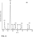
- FIG. 4 a larger part of a schematic WDX spectrum 400 is illustrated with peak positions 401 to 405 of peaks that represent fluorescence emissions which are characteristic for elements contained in the sample (i.e., the elemental composition of said sample).
- the background positions 406 to 411 illustrate positions in the vicinity of the peaks which could be used as measuring points for measuring the background intensities for respective peaks.
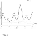
- peaks 501 to 505 often have overlapping regions so that the background intensity 520 (illustrated by the dashed line) is below the measured gross intensities of the peaks over large parts of the measured WDX spectrum. In other words, with such overlapping peak regions no measurement points can be found in the vicinity of the peaks where the respective background intensity could be measured.
- the background intensity also varies with the energy (diffraction angle). In realistic spectra, the background intensity is not a linear function but can even include steps at certain energies as schematically shown in FIG. 5 .
- the herein disclosed approach calculates the background intensities as described in the following to eliminate the need for background intensity measurements entirely.
- the system 100 has a mass fraction module 120 adapted to determine 1200 each of the one or more to-be-determined mass fractions MFi by using a calibration equation CE1 with the respective measured gross intensity 212 and respective calculated scattering efficiencies 112 as inputs.
- the calculated scattering efficiency is defined as the ratio between incoming intensity and scattered intensity for a particular elemental composition (of the test sample) and energy.
- the calibration equation CE1 (cf., FIG. 1 ) associates net intensities of characteristic fluorescence lines of the sample elements with respective mass fractions.
- the calibrating equation F9: c i a i I peak , i ⁇ d i s c E + ⁇ j o ij c j 1 + ⁇ j ⁇ ij c j illustrates that the net intensity for a particular peak i is obtained by subtracting the respective calculated scattering efficiency s ( c , E ) times a scaling factor d i from the measured gross intensity I peak,i of the particular peak.
- calibration samples of known elemental compositions (standards) are measured with the WDX spectrometer.
- the concentrations of said standards were determined with other measurement techniques. Using such measurements, one can empirically determine d i and the other parameters a i , o ij and ⁇ ij while keeping the concentrations of each standard fixed.
- the elemental composition c is known. That is, during calibration, the scattering efficiency s is calculated for each standard and the additional correction parameters d i is adjusted along with the other correction parameters a i , o ij and ⁇ ij .
- the respective parameters are determined based on the known properties of the standards (e.g., concentrations, geometry, density).
- the system may store different calibration parameters for different sample types (samples with different elemental compositions) in the calibration equation module 130 where the calibration parameters in the calibration equations may have different values for respective sample types.
- the system may further comprise a calibration module 110 which is configured to perform the above-described calibration step based on WDX measurement data obtained from respective standards.
- the calibration equation CE1 is used with fixed parameters to determine the mass fractions of the unknown test sample.
- the elemental composition is an input parameter to calculate the scattering efficiency.
- system 100 is for determining mass fractions of one or more elements in that test sample. This looks like a contradiction as the to-be-determined elemental composition of the test sample requires the knowledge of said elemental composition.
- the accuracy in the mass fractions of the elements required for the calculation of the scattering efficiency is far lower than the accuracy typically required for the final mass fraction result(s) to be determined for the one or more elements of the test sample 202. Therefore, the mass fractions of the particular elemental composition used for the calculation of the scattering efficiency is referred to mass fraction estimates.
- trace elements can be entirely ignored. In other words, it is sufficient to have estimates only for such elements with mass fractions exceeding a threshold value being characteristic for trace element mass fractions (e.g., only mass fractions of at least one percent). These elements are referred to as relevant elements herein. Trace elements in the test sample are irrelevant for the calculation of the scattering efficiency (and therefore the background intensity).
- the elemental composition estimates of the test sample with the accuracy as required for calculation the scattering efficiency can be obtained by two alternative implementations of an elemental composition module 121 of system 100.
- the elemental composition module 121 uses iteration module 121-1 adapted to execute an iterative method to estimate the elemental composition of the test sample.
- the iterative method is illustrated as a loop structure in the left branch of the determining 1200 step of FIG. 2 .
- the iteration module initializes 1210 current mass fraction estimates of the elements with arbitrary values. That is, the initial elemental composition which is used during a first iteration step for computing 1220 the calculated scattering efficiency includes arbitrary values for the concentrations of elements in the test sample.
- the relevant elements may already be known from the sample type of the test sample.
- This calculated scattering efficiency is computed 1220 for each gross intensity associated with a to-be-determined mass fraction. That is, in this implementation, the gross intensities of the relevant peaks in WDX spectrum are determined via the detector 204 by performing WDX measurements at the respective energies (i.e., at diffraction angles corresponding to the corresponding peak positions). The diffraction angles are adjusted accordingly using a goniometer with the monochromator 203. Thereby, the respective calculated scattering efficiency uses the current mass fraction estimates with the energy of the fluorescence line of the respective element. In other words, in the first iteration it uses the arbitrary mass fraction values from the initialization.
- the iteration module then computes 1230 the one or more to-be-determined mass fractions as the current mass fractions by using the calibration equation CE1 with respectively computed scattering efficiencies. That is, the values of the current mass fraction estimates (during the first iteration: the arbitrary values from the initialization) are now overwritten by the mass fraction values resulting from computing step 1230.
- the iteration module now performs a check 1235 whether the mass fraction difference MFD between the one or more to-be-determined mass fractions of the latest iteration and the respective one or more to-be-determined mass fractions of the preceding iteration exceed a predefined threshold T1.
- the mass fractions of the preceding iteration correspond to the arbitrary mass fraction values of the initialization. It is highly unlikely that after the first iteration MFD would already be smaller than or equal to the predefined threshold. This could only happen if the arbitrary mass fraction values of the initialization are already an almost perfect match with the elemental composition prevailing in the test sample.
- MFD is greater than T1
- the iteration module performs the next iteration by repeating 1240 the computing steps 1220, 1230.
- the computation 1230 of the to-be-determined mass fractions on the basis of the elemental composition as estimated in the previous iteration comes closer to the actual elemental composition of the test sample.
- the determined concentrations of the relevant elements in the test sample are closer to the actual real-world concentrations than the concentrations estimated during the previous iteration.
- the iteration module continues with the loop 1240 until the check function 1235 determines finally that the MFD has become smaller than or equal to the predefined threshold. Then, the termination condition of the loop 1240 is fulfilled and the estimated mass fraction values computed 1230 in the last iteration are provided 1250 as the to-be-determined mass fractions.
- elemental composition module 121 uses EDX quantification module 121-2 for determining the elemental composition of the test sample for the purpose of computing the calculated scattering efficiencies 112 for the respective peaks.
- the steps performed by the EDX quantification module 121-2 are shown with dash-dotted frames in FIG. 2 on the right hand of step 1200.
- the EDX quantification module obtains the one or more to-be-determined mass fractions via a quantification using a measurement result 213 of the Energy Dispersive X-Ray detector 206 (EDX detector).
- the EDX detector can be used to quickly obtain a sufficiently accurate estimate of the concentrations of all relevant elements for the purpose of calculated the scattering efficiencies at the relevant peaks.
- the computing steps 1220' and 1230' correspond to the steps 1220, 1230 performed in a single iteration of loop 1240.
- no iteration is necessary as the elemental composition for calculating the scattering intensities in step 1220' is already known from the EDX measurement.
- the measured gross intensities of the peaks and the calculated scattering intensities are used as inputs for the calibration equation CE1. This leads directly to the mass fraction values for the to-be-determined mass fractions MFi.
- the mass fraction results can be provided 1250 by the MF module 120, for example via a user interface, to an operator of a production system.
- the determined mass fractions may also be used to generate control instructions for the process control of an industrial process.
- FIGs. 6A , 6B illustrate mass fraction deviations of reevaluated standard samples for two different elements.
- the mass fractions of the standard samples were known from other measurements (Entered SC/PB Mass Fraction). These standard samples were used to determine the calibration parameters in the respective calibration equations.
- the mass fractions of Sc in FIG. 6A of were determined with three different methods: entirely ignoring the background intensity (rhombus symbol: No Bkg), using measured background intensities in the vicinity of the respective element peak (+ symbol: Measured Bkg), and using the herein disclosed approach based on calculated scattering efficiencies (x symbol: Theoretical Bkg).
- the mass fractions of Pb were determined by only using Measured Bkg (+) and Theoretical Bkg (x).
- Graph 610 in FIG. 6A shows the difference between the to-be-determined (evaluated) mass fraction of Sc and the entered (nominal) Sc mass fraction of the standards (y-axis) over the entered Sc mass fraction of the standard (x-axis).
- An indicator for a good quality of the calibration parameters is achieved, when all differences are close to zero.
- a positive difference at zero percent entered Sc mass fraction means, that an evaluated sample with actually zero mass fraction of Sc will give a positive, non-zero result (false positive).
- c Sc a Sc ( I net,Sc ) m Sc , where a Sc is the slope and m Sc is the matrix correction.
- I net,Sc is I gross,Sc for "No Bkg”
- I peak,Sc - d Sc s ( c , E ) for "Theoretical Bkg”.
- All samples contain BaO, TiOz and Sc 2 O 3 in different concentrations fused into a borate glass bead.
- Table 1 includes the values which are plotted in FIG.
- Theoretical Background (Theoretical Bkg) approach based on calculated scattering efficiencies gives the best results and no false positives. It is to be emphasized that the results obtained with the herein disclosed calculated background intensities are even far more accurate than the results obtained from the prior art approach where the background intensity is directly measured in the vicinity of the respective element peak.
- Graph 620 in FIG. 6B illustrates a similar result for Pb mass fractions in standard samples. However, graph 620 does not include the values for mass fractions determined with no background since the errors are too large to be depicted in graph 620.
- I net,Pb is I peak,Pb - I bkg,Pb for"Measured Bkg" and I peak,Pb - d Pb s(c, E ) for "Theoretical Bkg".
- FIG. 7 is a diagram that shows an example of a generic computer device 900 and a generic mobile computer device 950, which may be used with the techniques described here.
- computing device 900 may relate to system 100 (cf. FIG. 1 ).
- such a computer device 900 may be implemented as an integrated component of a wave-length dispersive X-ray fluorescence spectrometer.
- Computing device 950 is intended to represent various forms of mobile devices, such as personal digital assistants, cellular telephones, smart phones, and other similar computing devices.
- the computing device 950 may provide I/O means for a user to interact with the computing device 950 (e.g., for selecting the diffraction orders used for the analysis of the sample).
- the components shown here, their connections and relationships, and their functions, are meant to be exemplary only, and are not meant to limit implementations of the inventions described and/or claimed in this document.
- Computing device 900 includes a processor 902, memory 904, a storage device 906, a high-speed interface 908 connecting to memory 904 and high-speed expansion ports 910, and a low-speed interface 912 connecting to low-speed bus 914 and storage device 906.
- Each of the components 902, 904, 906, 908, 910, and 912 are interconnected using various busses, and may be mounted on a common motherboard or in other manners as appropriate.
- the processor 902 can process instructions for execution within the computing device 900, including instructions stored in the memory 904 or on the storage device 906 to display graphical information for a GUI on an external input/output device, such as display 916 coupled to high-speed interface 908.
- multiple processors and/or multiple buses may be used, as appropriate, along with multiple memories and types of memory.
- multiple computing devices 900 may be connected, with each device providing portions of the necessary operations (e.g., as a server bank, a group of blade servers, or a multi-processor system).
- the memory 904 stores information within the computing device 900.
- the memory 904 is a volatile memory unit or units.
- the memory 904 is a non-volatile memory unit or units.
- the memory 904 may also be another form of computer-readable medium, such as a magnetic or optical disk.
- the storage device 906 is capable of providing mass storage for the computing device 900.
- the storage device 906 may be or contain a computer-readable medium, such as a floppy disk device, a hard disk device, an optical disk device, or a tape device, a flash memory or other similar solid state memory device, or an array of devices, including devices in a storage area network or other configurations.
- a computer program product can be tangibly embodied in an information carrier.
- the computer program product may also contain instructions that, when executed, perform one or more methods, such as those described above.
- the information carrier is a computer- or machine-readable medium, such as the memory 904, the storage device 906, or memory on processor 902.
- the high-speed controller 908 manages bandwidth-intensive operations for the computing device 900, while the low-speed controller 912 manages lower bandwidth-intensive operations. Such allocation of functions is exemplary only.
- the high-speed controller 908 is coupled to memory 904, display 916 (e.g., through a graphics processor or accelerator), and to high-speed expansion ports 910, which may accept various expansion cards (not shown).
- low-speed controller 912 is coupled to storage device 906 and low-speed expansion port 914.
- the low-speed expansion port which may include various communication ports (e.g., USB, Bluetooth, Ethernet, wireless Ethernet) may be coupled to one or more input/output devices, such as a keyboard, a pointing device, a scanner, or a networking device such as a switch or router, e.g., through a network adapter.
- input/output devices such as a keyboard, a pointing device, a scanner, or a networking device such as a switch or router, e.g., through a network adapter.
- the computing device 900 may be implemented in a number of different forms, as shown in the figure. For example, it may be implemented as a standard server 920, or multiple times in a group of such servers. It may also be implemented as part of a rack server system 924. In addition, it may be implemented in a personal computer such as a laptop computer 922. Alternatively, components from computing device 900 may be combined with other components in a mobile device (not shown), such as device 950. Each of such devices may contain one or more of computing device 900, 950, and an entire system may be made up of multiple computing devices 900, 950 communicating with each other.
- Computing device 950 includes a processor 952, memory 964, an input/output device such as a display 954, a communication interface 966, and a transceiver 968, among other components.
- the device 950 may also be provided with a storage device, such as a microdrive or other device, to provide additional storage.
- a storage device such as a microdrive or other device, to provide additional storage.
- Each of the components 950, 952, 964, 954, 966, and 968 are interconnected using various buses, and several of the components may be mounted on a common motherboard or in other manners as appropriate.
- the processor 952 can execute instructions within the computing device 950, including instructions stored in the memory 964.
- the processor may be implemented as a chipset of chips that include separate and multiple analog and digital processors.
- the processor may provide, for example, for coordination of the other components of the device 950, such as control of user interfaces, applications run by device 950, and wireless communication by device 950.
- Processor 952 may communicate with a user through control interface 958 and display interface 956 coupled to a display 954.
- the display 954 may be, for example, a TFT LCD (Thin-Film-Transistor Liquid Crystal Display) or an OLED (Organic Light Emitting Diode) display, or other appropriate display technology.
- the display interface 956 may comprise appropriate circuitry for driving the display 954 to present graphical and other information to a user.
- the control interface 958 may receive commands from a user and convert them for submission to the processor 952.
- an external interface 962 may be provide in communication with processor 952, so as to enable near area communication of device 950 with other devices.
- External interface 962 may provide, for example, for wired communication in some implementations, or for wireless communication in other implementations, and multiple interfaces may also be used.
- the memory 964 stores information within the computing device 950.
- the memory 964 can be implemented as one or more of a computer-readable medium or media, a volatile memory unit or units, or a non-volatile memory unit or units.
- Expansion memory 984 may also be provided and connected to device 950 through expansion interface 982, which may include, for example, a SIMM (Single In Line Memory Module) card interface.
- SIMM Single In Line Memory Module
- expansion memory 984 may provide extra storage space for device 950, or may also store applications or other information for device 950.
- expansion memory 984 may include instructions to carry out or supplement the processes described above, and may include secure information also.
- expansion memory 984 may act as a security module for device 950, and may be programmed with instructions that permit secure use of device 950.
- secure applications may be provided via the SIMM cards, along with additional information, such as placing the identifying information on the SIMM card in a non-hackable manner.
- Device 950 may communicate wirelessly through communication interface 966, which may include digital signal processing circuitry where necessary. Communication interface 966 may provide for communications under various modes or protocols, such as GSM voice calls, SMS, EMS, or MMS messaging, CDMA, TDMA, PDC, WCDMA, CDMA2000, or GPRS, among others. Such communication may occur, for example, through radio-frequency transceiver 968. In addition, short-range communication may occur, such as using a Bluetooth, WiFi, or other such transceiver (not shown). In addition, GPS (Global Positioning System) receiver module 980 may provide additional navigation- and location-related wireless data to device 950, which may be used as appropriate by applications running on device 950.
- GPS Global Positioning System
- implementations of the systems and techniques described here can be realized in digital electronic circuitry, integrated circuitry, specially designed ASICs (application specific integrated circuits), computer hardware, firmware, software, and/or combinations thereof.
- ASICs application specific integrated circuits
- These various implementations can include implementation in one or more computer programs that are executable and/or interpretable on a programmable system including at least one programmable processor, which may be special or general purpose, coupled to receive data and instructions from, and to transmit data and instructions to, a storage system, at least one input device, and at least one output device.
- the systems and techniques described here can be implemented on a computer having a display device (e.g., a CRT (cathode ray tube) or LCD (liquid crystal display) monitor) for displaying information to the user and a keyboard and a pointing device (e.g., a mouse or a trackball) by which the user can provide input to the computer.
- a display device e.g., a CRT (cathode ray tube) or LCD (liquid crystal display) monitor
- a keyboard and a pointing device e.g., a mouse or a trackball
- Other kinds of devices can be used to provide for interaction with a user as well; for example, feedback provided to the user can be any form of sensory feedback (e.g., visual feedback, auditory feedback, or tactile feedback); and input from the user can be received in any form, including acoustic, speech, or tactile input.
- the systems and techniques described here can be implemented in a computing device that includes a back end component (e.g., as a data server), or that includes a middleware component (e.g., an application server), or that includes a front end component (e.g., a client computer having a graphical user interface or a Web browser through which a user can interact with an implementation of the systems and techniques described here), or any combination of such back end, middleware, or front end components.
- the components of the system can be interconnected by any form or medium of digital data communication (e.g., a communication network). Examples of communication networks include a local area network ("LAN”), a wide area network (“WAN”), and the Internet.
- LAN local area network
- WAN wide area network
- the Internet the global information network
- the computing device can include clients and servers.
- a client and server are generally remote from each other and typically interact through a communication network.
- the relationship of client and server arises by virtue of computer programs running on the respective computers and having a client-server relationship to each other.
Landscapes
- Physics & Mathematics (AREA)
- Health & Medical Sciences (AREA)
- Life Sciences & Earth Sciences (AREA)
- Chemical & Material Sciences (AREA)
- Analytical Chemistry (AREA)
- Biochemistry (AREA)
- General Health & Medical Sciences (AREA)
- General Physics & Mathematics (AREA)
- Immunology (AREA)
- Pathology (AREA)
- Spectroscopy & Molecular Physics (AREA)
- Analysing Materials By The Use Of Radiation (AREA)
Description
- The present invention generally relates to wave-length dispersive x-ray fluorescence spectroscopy, and more particularly relates to determining mass fractions of elements in a test sample from a spectrum of a wave-length dispersive x-ray fluorescence (WDX) spectrometer. The terms mass fraction of an element and concentration of an element are used as synonyms herein.
- In wave-length dispersive x-ray fluorescence (WDX) spectroscopy, an x-ray tube generates polychromatic primary radiation including characteristic lines of the tube material and Bremsstrahlung. The primary radiation is directed on a sample to be analyzed. The primary radiation generates x-ray fluorescence (XRF) emissions that are characteristic for the elements contained in the sample. Additionally, the primary radiation is scattered by the sample. The radiation coming from the sample (secondary radiation) is dispersed by a monochromator (typically a crystal) in the center of a goniometer, that allows various diffraction angles θ. This technique is based on Bragg's law (equation F1):

- The wavelength can be transferred to energy by equation F2:

- To quantify the concentration c (mass fraction) of a particular element in an unknown sample, the characteristic fluorescence intensity I of said element must be correlated to the concentration of the element by a conversion factor (slope) a:

- There may be additional corrections in equation F3, such as for example overlap and/or matrix corrections (known by a person skilled in the art) which are not discussed here for reasons of simplicity. The conversion factor (and potential further correction factors) is determined in a calibration step, where calibration samples with known concentrations of elements (mass fractions) to be analyzed are measured and the conversion factor is adjusted in such a way that the mass fractions calculated from the measured intensities by equation F3 best match the known mass fractions of the calibration samples.
- However, in the spectrum of an XRF spectrometer the characteristic fluorescence intensities of the elements are superimposed with other intensities referred to as background. The relevant net intensity (Inet ) for a particular element can be determined by subtracting the background (Ibackgr ) from the intensity measured at the position of the peak of the respective fluorescence line of the element (Ipeak ):

- Since the background under the peak is not directly accessible, it is interpolated or extrapolated from intensities measured before and/or after the respective peak.
- While the spectrometer can scan a wide range of angles to produce a spectrum of a test sample, in practical application only single points are measured to get good accuracy in the shortest time possible. In other words, many applications (e.g., WDX spectroscopy used in steel production) are very time critical to avoid the necessity to stop a production line while waiting for the measurement and evaluation of the product composition. Nevertheless, besides the intensities at the peak positions, additional points for the background intensities need to be measured by prior art approaches, thus adding to the overall measurement time.
- A further problem of prior art approaches when using background points is to find a region in the spectrum where the background intensity can be determined in an undisturbed way because typically multiple characteristic fluorescence peaks of the multiple elements in the test sample are present in the vicinity of the peak to be analyzed thus hiding the background intensities. To overcome this problem, prior art approaches typically increase the resolution of the measurement by using a different crystal (e.g., LiF220 instead of LiF200), or by using a smaller collimator that restricts the angular divergence of the beam hitting the monochromator. However, both approaches reduce the overall intensity quite significantly and thus increase again the overall measurement time.
- Another prior art approach to remedy this problem was published in 1976 by Feather and Willis in "A simple method for background and matrix correction of spectral peaks in trace element determination by X-ray fluorescence spectrometry. X-Ray Spectrom., 5: 41-48. https://doi.org/10.1002/xrs.1300050110". This approach uses measured background intensities of blanks (calibration samples not containing the analyte) and corrects these for matrix effects either by calculating the mass absorption coefficient or by measuring the Compton scattered tube line. That is, this approach calculates sample specific backgrounds by using dedicated samples that do not contain the analyte (blank samples) during calibration. It is thus increasing the efforts necessary during calibration and evaluation. Further, it is only applicable where blank samples are readily available. A related calibration curve method using a fluorescent X-ray intensity and an intensity ratio of scattered rays such as Compton scattered rays is disclosed in
WO 2021/16163 - There is therefore a need for systems and methods that provide mass fractions of one or more elements in a test sample by using a wavelength-dispersive X-ray fluorescence spectrometer reducing measurement time to a minimum with low efforts during calibration and evaluation. In particular, in time critical production processes (e.g., steel production) the measurement time for determining such mass fractions needs to be reduced to the shortest possible time interval. This problem is solved by the features according to the independent claims by eliminating the necessity to measure background points thus reducing the overall measurement time needed to evaluate an unknown sample. Additionally, the claimed invention allows to use a lower resolution of the WDX spectrometer, thus further allowing for higher overall intensities with shorter measurement times.
- In WDX spectroscopy the background is dominated by the scattered radiation from the x-ray tube on the sample (Iscatter ):

- The herein disclosed approach is based on a calculated scattered radiation using the sample composition (i.e., the elemental composition of the sample specified by the mass fractions of the elements included in the sample) as a base for calculation. Gaining the knowledge of the sample composition can be achieved by using an iterative procedure or by measuring the sample using an additional energy-dispersive X-ray (EDX) detector as described in detail further down below.
- The intensity of the scattered radiation for a given incidence intensity (Iincidence ), energy (E), and sample composition (c) can be calculated according to:

- Utilizing the calibration equation F3 from above for determining the mass fraction ci for a particular element i leads to:

- Since Iincidence,i is independent on the sample composition it can be combined with the calibration parameter bi to form:

- The calibration parameters for equation F8 are determined during a calibration procedure which is performed prior to the determination of mass fractions in a test sample. During the calibration procedure, the scattering efficiency s is calculated for each calibration sample and the additional correction parameter (di ) is adjusted along with the other correction parameters. In other words, for finalizing the calibration equation F8, the calibration parameters are adjusted. In the above example this adjustment is performed for the parameters ai and di . For the calibration, samples with known sample properties are used. Such sample properties are primarily the concentrations (mass fractions) reflecting the elemental compositions of the calibration samples, but also other properties such as the sample geometry and density may be useful. During evaluation of a test sample, the calibration equation F8 is then used with fixed parameters to determine the mass fraction of the test sample.
- It is to be noted that equation F8 shows a simplified model equation where only the two relevant parameters are shown: a and d. However, in reality such model equation for X-Ray Fluorescence (XRF) typically is more complex.

- In one embodiment, a computer-implemented method is provided for determining mass fractions of one or more elements in a test sample based on a measurement with a wave-length dispersive x-ray fluorescence (WDX) spectrometer. The method can be executed by a computer system embodiment with modules which are configured to execute the steps of the computer implemented method. This is enabled by a computer program product embodiment having computer readable instructions that, when loaded into a memory of a computer system and executed by at least one processor of the computer system, causes the computer system to perform the computer implemented method disclosed herein. In other words, the computer program product defines the functions performed by the respective modules of the computer system.
- The WDX spectrometer measures one or more gross-intensities associated with respective one or more elements with corresponding one or more to-be-determined mass fractions in the test sample. In practical applications, the number of to-be-determined mass fractions may vary significantly. In some applications, the entire elemental composition of the test sample (e.g., all elements including trace elements in said sample) is to be determined. In other applications the determination of the concentration of a single particular element in the test sample or a subset of elements is sufficient. The WDX measurement values are then received by a computer system for the sample evaluation. The computer system may be implemented as an integrated component of the WDX spectrometer or it may be communicatively coupled with the WDX spectrometer such that the measurement values can be received via standard data communication means.
- The computer system then determines each of the one or more to-be-determined mass fractions by using a calibration equation with the respective measured gross intensity and a respective calculated scattering efficiency as inputs. The calibration equation has a set of calibration parameters obtained from a previous calibration step using one or more calibration samples with known elemental compositions. The calculated scattering efficiency depends on the energy of the fluorescence line of the respective element and the particular elemental composition of the test sample. The calibration equation associates the net intensities of characteristic fluorescence lines of the sample elements with respective mass fractions as illustrated by the example equation F9. Thereby, the net intensity for a particular peak is obtained by subtracting a respective calculated scattering efficiency times di from the measured gross intensity of the particular peak. The particular elemental composition of the test sample for the calculation of the scattering efficiency can be determined by an elemental composition module of the system using one of the following alternative implementations.
- In a first implementation alternative, an iteration module is used for iteratively determining mass fraction estimates for the particular elemental composition based on the measured gross-intensities associated with elements in the test sample.
- Current mass fraction estimates of said elements in the test sample are initialized with arbitrary values. For example, such start values of the respective concentrations may be set to
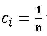
- Then, the iteration module computes the one or more to-be-determined mass fractions as the current mass fraction estimates using the calibration equation (by keeping the calibration parameters fixed). For example, when using the calibration equation F9, di, ai , oij and aij are kept fix.
- The computing steps are then repeated as long as the difference between the one or more to-be-determined mass fractions of the latest iteration and the respective one or more to-be-determined mass fractions of the preceding iteration exceed a predefined threshold. In other word, the iteration module checks after each iteration if the mass fraction values which were calculated in the latest iteration show a greater change over the previous iteration than the predefined threshold. Thereby, the same threshold value may be used for all mass fractions. Alternatively, element specific threshold values may be used. As long as the deviations are still exceeding the threshold value, the iteration module performs a further iteration. Otherwise, the iteration stops and the one or more mass fractions of the latest iteration are provided as the elemental composition of the test sample.
- In a second implementation alternative, an EDX quantification module is used to obtain the one or more to-be-determined mass fractions from a quantification using an Energy Dispersive X-Ray (EDX) detector in addition to the WDX detector of the WDX spectrometer. In this implementation, the elemental composition needed for the calculation of the scattering efficiency can be derived from the EDX measurement and evaluation. Thereby, the measurement of the test sample with the EDX detector may be performed before measuring the sample with the WDX spectrometer, in parallel (simultaneously) with the measuring of the sample with the WDX spectrometer, or after measuring the sample with the WDX spectrometer. The simultaneous measurement is possible because the radiation emitted by the sample is emitted in all directions. Therefore, the monochromator of the WDX spectroscope and the EDX detector can be located at different locations. Typically, there are two different exit holes in the vacuum chamber where the test sample is placed. The radiation directed to the monochromator exits through one of these holes and the radiation directed to the EDX detector exits through the other hole. Quantification options with XRF are described in detail in the "Handbook of X-Ray Spectrometry 2nd Edition. ISBN: 978-0824706005, November 27, 2001 by CRC Press", chapter 4 (Spectrum Evaluation) and chapter 5 (Quantification of Infinitely Thick Specimens by XRF Analysis).
- It is to be noted that also the first implementation alternative may use the additional EDX detector to measure the gross intensities for said sample. However, when using the first implementation alternative, the WDX spectrometer is sufficient for iteratively determining the one or more to-be-determined mass fractions.
- Further aspects of the invention will be realized and attained by means of the elements and combinations particularly depicted in the appended claims. It is to be understood that both, the foregoing general description and the following detailed description are exemplary and explanatory only and are not restrictive of the invention as described.
-
-
FIG. 1 includes a block diagram of an example embodiment of a computer system for determining mass fractions of one or more elements in a test sample based on a measurement of said sample with a wave-length dispersive x-ray fluorescence spectrometer; -
FIG. 2 is a simplified flow chart of a computer-implemented method for determining mass fractions of one or more elements in a test sample according to an embodiment; -
FIG. 3 illustrates the net intensity of a peak in a WDX spectrum; -
FIG. 4 illustrates a schematic WDX spectrum with peak and background positions; -
FIG. 5 illustrates overlapping peaks of an exemplary WDX spectrum hiding the background; -
FIG. 6A illustrates Sc mass fraction deviation of reevaluated standard samples; -
FIG. 6B illustrates Pb mass fraction deviation of reevaluated standard samples; and -
FIG. 7 is a diagram that shows an example of a generic computer device and a generic mobile computer device, which may be used with the techniques described herein. -
FIG. 1 includes a block diagram of an example embodiment of acomputer system 100 for determining mass fractions of one or more elements in atest sample 202 based on a measurement of said sample with a wave-length dispersivex-ray fluorescence spectrometer 200. Thesystem 100 ofFIG. 1 is described in the context of the simplified flow chart of a computer-implementedmethod 1000 for determining such mass fractions as illustrated inFIG. 2 . Therefore, the following description refers to reference numbers used inFIG. 1 andFIG. 2 . Thesystem 100 is thereby configured to execute themethod 1000 when loading a respective computer program into a memory of the system and executing said program with processing means of the system. Said computer program product implements the functional modules of thesystem 100 as disclosed herein. - In the example embodiment of
FIG. 1 , thesystem 100 is communicatively coupled with thespectrometer 200 via an appropriate interface (not shown). In an alternative embodiment, thecomputer system 100 may be an integrated component of the wave-length dispersivex-ray fluorescence spectrometer 200. In both embodiments,system 100 can receive 1100gross intensities 212 obtained bydetector 204 of thespectrometer 200 via an appropriate interface (not shown). The functioning of thespectrometer 200 has been described to a large extent in the background section. In general, a person skilled in the art knows how thespectrometer 200 can obtain thegross intensities 212 fromsample 202. Nevertheless, the functioning is briefly summarized in the following with a reference toFIG. 1 . - The
x-ray tube 201 generates polychromatic primary radiation 201-r including characteristic lines of the tube material and Bremsstrahlung which is directed on asample 202 to be analyzed. This primary radiation generates X-ray fluorescence emissions that are characteristic for the elements contained in the sample. Additionally, the primary radiation is scattered by the sample. The radiation 202-r emitted by thesample 202 containing X-ray fluorescence and scattered primary radiation is analyzed by measuring (via WDX detector 204), with a goniometer, the radiation 203-r reflected by themonochromator 203 of the spectrometer at various diffraction angles θ. In an alternative embodiment, an additional Energy Dispersive X-Ray (EDX)detector 206 can be integrated with theWDX spectrometer 200 to measure radiation 202-r' emitted by thesample 202. The sample emits radiation into all directions. Therefore, the exemplary beams 202-r and 202-r' represent the radiation emitted by the sample into two different directions. In one direction, the emitted radiation 202-r hits themonochromator 203. In another direction, the emitted radiation 202-r' hits the EDX detector 206 (in the alternative embodiment). - As described above, the
computer system 100 is communicatively coupled to thedetector 204 of the WDX spectrometer. In an alternative embodiment, thesystem 100 is additionally coupled to theEDX detector 206 via an appropriate interface (not shown). The computer system receives 1100 one or moregross intensities 212 associated with respective one or more elements with corresponding one or more to-be-determined mass fractions MFi in thetest sample 202 obtained by thedetector 204 of theWDX spectrometer 200 from saidtest sample 202. That is, while the goniometer ofWDX spectrometer 200 changes the diffraction angle θ, the energy of the radiation 203-r also changes. In the WDX spectrometer, the goniometer is an instrument that allows the monochromator to be rotated to a precise angular position. When thedetector 204 measures a peak, the energy of this peak is characteristic for a particular element in thetest sample 202. The mass fraction (concentration) of this particular element is reflected by the net intensity of this peak. However, what is measured by thedetector 204 is the gross intensity of the peak. - This is illustrated in
FIG. 3 showing a part of aschematic WDX spectrum 300. The shown part ofspectrum 300 includes a peak atposition 301 whosegross intensity 310 is measured at a certain diffraction angle θ. The peak represents the fluorescence emission which is characteristic for a particular element contained in the sample. Thebackground intensity 320 which is caused by the primary scattered radiation (illustrated by the horizontal dashed line in this example) could be measured atposition 302. The background is included in thegross intensity 310. The requirednet intensity 330 is the difference between thegross intensity 310 and thebackground intensity 320. - Turning briefly to
FIG. 4 , a larger part of aschematic WDX spectrum 400 is illustrated withpeak positions 401 to 405 of peaks that represent fluorescence emissions which are characteristic for elements contained in the sample (i.e., the elemental composition of said sample). The background positions 406 to 411 illustrate positions in the vicinity of the peaks which could be used as measuring points for measuring the background intensities for respective peaks. - However, in a
realistic WDX spectrum 500, as illustratedFIG. 5 ,peaks 501 to 505 often have overlapping regions so that the background intensity 520 (illustrated by the dashed line) is below the measured gross intensities of the peaks over large parts of the measured WDX spectrum. In other words, with such overlapping peak regions no measurement points can be found in the vicinity of the peaks where the respective background intensity could be measured. As illustrated inFIG. 5 , the background intensity also varies with the energy (diffraction angle). In realistic spectra, the background intensity is not a linear function but can even include steps at certain energies as schematically shown inFIG. 5 . Therefore, it would not be sufficient to measure a single background intensity value anywhere in a WDX spectrum and subtract this value from all measured peak gross intensities. Rather, for each peak, the respective background intensities would need to be measured, which is simply not possible in theexample spectrum 500. To mitigate this problem, prior art approaches increase the resolution of the measurement by using a different crystal (e.g., LiF220 instead of LiF200), or by using a smaller collimator that restricts the angular divergence of the beam hitting the monochromator. However, both prior art approaches reduce the overall intensity quite significantly and thus increase overall measurement time which is contrary to the objective to allow measurements in time critical applications, such as steel production. It is to be noted that the schematic spectra inFIGs. 3 to 5 show continuous spectrum lines. However, in a real WDX measurement application, measurements are only taken at the specific energy positions which are indicated as solid arrows inFIGs. 3 and4 . For reasons of simplicity, such specific energy positions are not highlighted inFIG. 5 . However, a person skilled in the art will know where the measurement points are to be positioned. - Therefore, the herein disclosed approach calculates the background intensities as described in the following to eliminate the need for background intensity measurements entirely.
- The
system 100 has amass fraction module 120 adapted to determine 1200 each of the one or more to-be-determined mass fractions MFi by using a calibration equation CE1 with the respective measuredgross intensity 212 and respective calculated scatteringefficiencies 112 as inputs. As mentioned earlier, the calculated scattering efficiency is defined as the ratio between incoming intensity and scattered intensity for a particular elemental composition (of the test sample) and energy. - The calibration equation CE1 (cf.,
FIG. 1 ) associates net intensities of characteristic fluorescence lines of the sample elements with respective mass fractions. The calibrating equation F9:
calibration equation module 130 where the calibration parameters in the calibration equations may have different values for respective sample types. For example, the system may further comprise acalibration module 110 which is configured to perform the above-described calibration step based on WDX measurement data obtained from respective standards. - During evaluation of the
test sample 202, the calibration equation CE1 is used with fixed parameters to determine the mass fractions of the unknown test sample. In the calibration equation, the elemental composition is an input parameter to calculate the scattering efficiency. On the other hand,system 100 is for determining mass fractions of one or more elements in that test sample. This looks like a contradiction as the to-be-determined elemental composition of the test sample requires the knowledge of said elemental composition. However, the accuracy in the mass fractions of the elements required for the calculation of the scattering efficiency is far lower than the accuracy typically required for the final mass fraction result(s) to be determined for the one or more elements of thetest sample 202. Therefore, the mass fractions of the particular elemental composition used for the calculation of the scattering efficiency is referred to mass fraction estimates. For the calculation of the scattering efficiency trace elements can be entirely ignored. In other words, it is sufficient to have estimates only for such elements with mass fractions exceeding a threshold value being characteristic for trace element mass fractions (e.g., only mass fractions of at least one percent). These elements are referred to as relevant elements herein. Trace elements in the test sample are irrelevant for the calculation of the scattering efficiency (and therefore the background intensity). - The elemental composition estimates of the test sample with the accuracy as required for calculation the scattering efficiency can be obtained by two alternative implementations of an
elemental composition module 121 ofsystem 100. In a first implementation, theelemental composition module 121 uses iteration module 121-1 adapted to execute an iterative method to estimate the elemental composition of the test sample. The iterative method is illustrated as a loop structure in the left branch of the determining 1200 step ofFIG. 2 . Before starting theloop 1240, the iteration module initializes 1210 current mass fraction estimates of the elements with arbitrary values. That is, the initial elemental composition which is used during a first iteration step for computing 1220 the calculated scattering efficiency includes arbitrary values for the concentrations of elements in the test sample. For example, the relevant elements may already be known from the sample type of the test sample. This calculated scattering efficiency is computed 1220 for each gross intensity associated with a to-be-determined mass fraction. That is, in this implementation, the gross intensities of the relevant peaks in WDX spectrum are determined via thedetector 204 by performing WDX measurements at the respective energies (i.e., at diffraction angles corresponding to the corresponding peak positions). The diffraction angles are adjusted accordingly using a goniometer with themonochromator 203. Thereby, the respective calculated scattering efficiency uses the current mass fraction estimates with the energy of the fluorescence line of the respective element. In other words, in the first iteration it uses the arbitrary mass fraction values from the initialization. - In the loop, the iteration module then computes 1230 the one or more to-be-determined mass fractions as the current mass fractions by using the calibration equation CE1 with respectively computed scattering efficiencies. That is, the values of the current mass fraction estimates (during the first iteration: the arbitrary values from the initialization) are now overwritten by the mass fraction values resulting from computing
step 1230. - The iteration module now performs a
check 1235 whether the mass fraction difference MFD between the one or more to-be-determined mass fractions of the latest iteration and the respective one or more to-be-determined mass fractions of the preceding iteration exceed a predefined threshold T1. In the first iteration, the mass fractions of the preceding iteration correspond to the arbitrary mass fraction values of the initialization. It is highly unlikely that after the first iteration MFD would already be smaller than or equal to the predefined threshold. This could only happen if the arbitrary mass fraction values of the initialization are already an almost perfect match with the elemental composition prevailing in the test sample. In case MFD is greater than T1, the iteration module performs the next iteration by repeating 1240 the computing steps 1220, 1230. - With each iteration, the
computation 1230 of the to-be-determined mass fractions on the basis of the elemental composition as estimated in the previous iteration comes closer to the actual elemental composition of the test sample. In other words, in each iteration, the determined concentrations of the relevant elements in the test sample are closer to the actual real-world concentrations than the concentrations estimated during the previous iteration. The iteration module continues with theloop 1240 until thecheck function 1235 determines finally that the MFD has become smaller than or equal to the predefined threshold. Then, the termination condition of theloop 1240 is fulfilled and the estimated mass fraction values computed 1230 in the last iteration are provided 1250 as the to-be-determined mass fractions. - As this implementation requires the WDX measurement of the gross-intensities of all relevant element peaks, it can be advantageously used in scenarios where anyway a large number of mass fractions is to be determined form the measured WDX spectrum. The measurement time which would be needed in prior art approaches to measure background intensities in the vicinities of the relevant element peaks is saved. Further, in complex spectra with many overlays in the relevant peaks background intensities could not be measured at all. However, the implementation via the iteration module still allows to determine the mass fractions of all elements in the test sample (including trace elements) via the respective calculated scattering efficiencies which may be based on the relevant elements only.
- In the alternative implementation,
elemental composition module 121 uses EDX quantification module 121-2 for determining the elemental composition of the test sample for the purpose of computing thecalculated scattering efficiencies 112 for the respective peaks. The steps performed by the EDX quantification module 121-2 are shown with dash-dotted frames inFIG. 2 on the right hand ofstep 1200. In this implementation, the EDX quantification module obtains the one or more to-be-determined mass fractions via a quantification using ameasurement result 213 of the Energy Dispersive X-Ray detector 206 (EDX detector). The EDX detector can be used to quickly obtain a sufficiently accurate estimate of the concentrations of all relevant elements for the purpose of calculated the scattering efficiencies at the relevant peaks. The gross intensities for determining highly accurate to-be-determined mass fractions are still obtained with theWDX detector 204. The EDX detector is merely used to speed up the determination of the elemental composition which is required as an input for computing the calculated scattering efficiencies. The quantifying 1210' of mass fractions from EDX detector measurements is known in the art. This quantifying step 1210' allows to determine the elemental composition estimate separately from the WDX measurements of the peakgross intensities 212. - The computing steps 1220' and 1230' correspond to the
steps loop 1240. In the EDX embodiment, no iteration is necessary as the elemental composition for calculating the scattering intensities in step 1220' is already known from the EDX measurement. To compute the mass fractions based on the determined net intensities of the respective peaks, the measured gross intensities of the peaks and the calculated scattering intensities are used as inputs for the calibration equation CE1. This leads directly to the mass fraction values for the to-be-determined mass fractions MFi. Thereby, for theMF module 120 it makes no difference, whether the measurement of thetest sample 202 with theEDX detector 206 is performed before, simultaneously with or after measuring the sample with thedetector 204 of the WDX spectrometer. The simultaneous measurement is advantageous in that no additional time losses occur, whereas when performing EDX and WDX measurements subsequently, the time of both measurements is needed before the computation of the mass fractions can be executed. The mass fraction results can be provided 1250 by theMF module 120, for example via a user interface, to an operator of a production system. The determined mass fractions may also be used to generate control instructions for the process control of an industrial process. -
FIGs. 6A ,6B illustrate mass fraction deviations of reevaluated standard samples for two different elements. The mass fractions of the standard samples were known from other measurements (Entered SC/PB Mass Fraction). These standard samples were used to determine the calibration parameters in the respective calibration equations. The mass fractions of Sc inFIG. 6A of were determined with three different methods: entirely ignoring the background intensity (rhombus symbol: No Bkg), using measured background intensities in the vicinity of the respective element peak (+ symbol: Measured Bkg), and using the herein disclosed approach based on calculated scattering efficiencies (x symbol: Theoretical Bkg). InFIG. 6B the mass fractions of Pb were determined by only using Measured Bkg (+) and Theoretical Bkg (x). -
Graph 610 inFIG. 6A shows the difference between the to-be-determined (evaluated) mass fraction of Sc and the entered (nominal) Sc mass fraction of the standards (y-axis) over the entered Sc mass fraction of the standard (x-axis). An indicator for a good quality of the calibration parameters is achieved, when all differences are close to zero. A positive difference at zero percent entered Sc mass fraction means, that an evaluated sample with actually zero mass fraction of Sc will give a positive, non-zero result (false positive). - The calibration equation in this example is:
cSc = aSc (Inet,Sc ) mSc, where aSc is the slope and mSc is the matrix correction. Inet,Sc is Igross,Sc for "No Bkg", Ipeak,Sc - Ibkg,Sc for"Measured Bkg" and Ipeak,Sc - dSc s( c, E) for "Theoretical Bkg". All samples contain BaO, TiOz and Sc2O3 in different concentrations fused into a borate glass bead.Table 1: includes the values which are plotted in FIG. 6A Entered Sc Mass Fraction Evaluated Sc Mass Fraction without Background Difference Evaluated Sc Mass Fraction with Measured Background Difference Evaluated Sc Mass Fraction with Theoretical Background Difference 0,00% 0,07% 0,07% 0,02% 0,02% 0,00% 0,00% 0,00% 0,08% 0,08% 0,03% 0,03% 0,00% 0,00% 0,00% 0,11% 0,11% 0,05% 0,05% 0,00% 0,00% 0,00% 0,11% 0,11% 0,04% 0,04% 0,00% 0,00% 0,00% 0,10% 0,10% 0,03% 0,03% 0,00% 0,00% 0,00% 0,08% 0,08% 0,03% 0,03% 0,00% 0,00% 2,00% 2,07% 0,07% 2,05% 0,05% 2,04% 0,04% 3,00% 3,04% 0,04% 3,02% 0,02% 3,00% 0,00% 5,00% 4,95% -0,05% 4,96% -0,04% 4,96% -0,04% 7,00% 6,91% -0,09% 6,94% -0,06% 6,96% -0,04% - No Background is showing a clear trend of positive differences below 4% Sc mass fraction and negative differences above 4 %. This indicates that there is a systematic error, here the missing background correction. At 0 % entered Sc mass fraction, using no background leads to significant false positives.
- Using an intensity in the vicinity of the Sc KA peak as a measured background (Measured Bkg) already gives a better result. However, still a similar trend can be observed and the false positives are still visible.
- Using the herein disclosed Theoretical Background (Theoretical Bkg) approach based on calculated scattering efficiencies gives the best results and no false positives. It is to be emphasized that the results obtained with the herein disclosed calculated background intensities are even far more accurate than the results obtained from the prior art approach where the background intensity is directly measured in the vicinity of the respective element peak.
-
Graph 620 inFIG. 6B illustrates a similar result for Pb mass fractions in standard samples. However,graph 620 does not include the values for mass fractions determined with no background since the errors are too large to be depicted ingraph 620. The calibration equation in this example is:
cPb = aPb (Inet,Pb + oPb ) mPb, where aPb is the slope, oPb is the overlap correction and mPb is the matrix correction. Inet,Pb is Ipeak,Pb - Ibkg,Pb for"Measured Bkg" and Ipeak,Pb -dPb s(c, E) for "Theoretical Bkg". Very different types of standards - plastics (ABS), fused borate glass beads (Fused Bead) and alloys (Brass and Cu Alloy) are part of the calibration. All standards show substantially different background contributions.Table 2: includes the values which are plotted in FIG. 6B Entered Pb Mass Fraction Sample Type Evaluated Pb Mass Fraction with Measured Background Difference Evaluated Pb Mass Fraction with Theoretical Background Difference 0,001% ABS 0,008% 0,008% 0,003% 0,003% 0,002% ABS 0,008% 0,007% 0,000% -0,002% 0,002% ABS 0,014% 0,011% 0,004% 0,001% 0,006% ABS 0,020% 0,014% 0,006% 0,000% 0,009% ABS 0,019% 0,010% 0,007% -0,002% 0,048% ABS 0,056% 0,008% 0,050% 0,002% 0,050% ABS 0,059% 0,010% 0,047% -0,003% 0,095% ABS 0,105% 0,010% 0,096% 0,001% 0,143% ABS 0,156% 0,013% 0,146% 0,002% 0,278% Fused Bead 0,152% -0,126% 0,280% 0,002% 0,780% Brass 0,475% -0,305% 0,777% -0,003% 1,620% Cu Alloy 1,245% -0,375% 1,561% -0,059% 1,670% Brass 1,340% -0,330% 1,630% -0,040% - Using an intensity in the vicinity of the Pb LA peak as a measured background shows low differences for all ABS samples but high differences for all other sample types. This results from the problem to find an undisturbed region in the spectrum, where the measured background intensity is representative for the actual background (see
FIG. 5 ). Using the herein disclosed Theoretical Background approach gives the best result, being able to provide a good background estimate for all the different sample types. -
FIG. 7 is a diagram that shows an example of ageneric computer device 900 and a genericmobile computer device 950, which may be used with the techniques described here. In some embodiments,computing device 900 may relate to system 100 (cf.FIG. 1 ). As mentioned earlier, such acomputer device 900 may be implemented as an integrated component of a wave-length dispersive X-ray fluorescence spectrometer.Computing device 950 is intended to represent various forms of mobile devices, such as personal digital assistants, cellular telephones, smart phones, and other similar computing devices. In the context of this disclosure thecomputing device 950 may provide I/O means for a user to interact with the computing device 950 (e.g., for selecting the diffraction orders used for the analysis of the sample). The components shown here, their connections and relationships, and their functions, are meant to be exemplary only, and are not meant to limit implementations of the inventions described and/or claimed in this document. -
Computing device 900 includes aprocessor 902,memory 904, astorage device 906, a high-speed interface 908 connecting tomemory 904 and high-speed expansion ports 910, and a low-speed interface 912 connecting to low-speed bus 914 andstorage device 906. Each of thecomponents processor 902 can process instructions for execution within thecomputing device 900, including instructions stored in thememory 904 or on thestorage device 906 to display graphical information for a GUI on an external input/output device, such asdisplay 916 coupled to high-speed interface 908. In other implementations, multiple processors and/or multiple buses may be used, as appropriate, along with multiple memories and types of memory. Also,multiple computing devices 900 may be connected, with each device providing portions of the necessary operations (e.g., as a server bank, a group of blade servers, or a multi-processor system). - The
memory 904 stores information within thecomputing device 900. In one implementation, thememory 904 is a volatile memory unit or units. In another implementation, thememory 904 is a non-volatile memory unit or units. Thememory 904 may also be another form of computer-readable medium, such as a magnetic or optical disk. - The
storage device 906 is capable of providing mass storage for thecomputing device 900. In one implementation, thestorage device 906 may be or contain a computer-readable medium, such as a floppy disk device, a hard disk device, an optical disk device, or a tape device, a flash memory or other similar solid state memory device, or an array of devices, including devices in a storage area network or other configurations. A computer program product can be tangibly embodied in an information carrier. The computer program product may also contain instructions that, when executed, perform one or more methods, such as those described above. The information carrier is a computer- or machine-readable medium, such as thememory 904, thestorage device 906, or memory onprocessor 902. - The high-
speed controller 908 manages bandwidth-intensive operations for thecomputing device 900, while the low-speed controller 912 manages lower bandwidth-intensive operations. Such allocation of functions is exemplary only. In one implementation, the high-speed controller 908 is coupled tomemory 904, display 916 (e.g., through a graphics processor or accelerator), and to high-speed expansion ports 910, which may accept various expansion cards (not shown). In the implementation, low-speed controller 912 is coupled tostorage device 906 and low-speed expansion port 914. The low-speed expansion port, which may include various communication ports (e.g., USB, Bluetooth, Ethernet, wireless Ethernet) may be coupled to one or more input/output devices, such as a keyboard, a pointing device, a scanner, or a networking device such as a switch or router, e.g., through a network adapter. - The
computing device 900 may be implemented in a number of different forms, as shown in the figure. For example, it may be implemented as astandard server 920, or multiple times in a group of such servers. It may also be implemented as part of arack server system 924. In addition, it may be implemented in a personal computer such as alaptop computer 922. Alternatively, components fromcomputing device 900 may be combined with other components in a mobile device (not shown), such asdevice 950. Each of such devices may contain one or more ofcomputing device multiple computing devices -
Computing device 950 includes aprocessor 952,memory 964, an input/output device such as adisplay 954, acommunication interface 966, and atransceiver 968, among other components. Thedevice 950 may also be provided with a storage device, such as a microdrive or other device, to provide additional storage. Each of thecomponents - The
processor 952 can execute instructions within thecomputing device 950, including instructions stored in thememory 964. The processor may be implemented as a chipset of chips that include separate and multiple analog and digital processors. The processor may provide, for example, for coordination of the other components of thedevice 950, such as control of user interfaces, applications run bydevice 950, and wireless communication bydevice 950. -
Processor 952 may communicate with a user throughcontrol interface 958 anddisplay interface 956 coupled to adisplay 954. Thedisplay 954 may be, for example, a TFT LCD (Thin-Film-Transistor Liquid Crystal Display) or an OLED (Organic Light Emitting Diode) display, or other appropriate display technology. Thedisplay interface 956 may comprise appropriate circuitry for driving thedisplay 954 to present graphical and other information to a user. Thecontrol interface 958 may receive commands from a user and convert them for submission to theprocessor 952. In addition, anexternal interface 962 may be provide in communication withprocessor 952, so as to enable near area communication ofdevice 950 with other devices.External interface 962 may provide, for example, for wired communication in some implementations, or for wireless communication in other implementations, and multiple interfaces may also be used. - The
memory 964 stores information within thecomputing device 950. Thememory 964 can be implemented as one or more of a computer-readable medium or media, a volatile memory unit or units, or a non-volatile memory unit or units. Expansion memory 984 may also be provided and connected todevice 950 throughexpansion interface 982, which may include, for example, a SIMM (Single In Line Memory Module) card interface. Such expansion memory 984 may provide extra storage space fordevice 950, or may also store applications or other information fordevice 950. Specifically, expansion memory 984 may include instructions to carry out or supplement the processes described above, and may include secure information also. Thus, for example, expansion memory 984 may act as a security module fordevice 950, and may be programmed with instructions that permit secure use ofdevice 950. In addition, secure applications may be provided via the SIMM cards, along with additional information, such as placing the identifying information on the SIMM card in a non-hackable manner. - The memory may include, for example, flash memory and/or NVRAM memory, as discussed below. In one implementation, a computer program product is tangibly embodied in an information carrier. The computer program product contains instructions that, when executed, perform one or more methods, such as those described above. The information carrier is a computer- or machine-readable medium, such as the
memory 964, expansion memory 984, or memory onprocessor 952, that may be received, for example, overtransceiver 968 orexternal interface 962. -
Device 950 may communicate wirelessly throughcommunication interface 966, which may include digital signal processing circuitry where necessary.Communication interface 966 may provide for communications under various modes or protocols, such as GSM voice calls, SMS, EMS, or MMS messaging, CDMA, TDMA, PDC, WCDMA, CDMA2000, or GPRS, among others. Such communication may occur, for example, through radio-frequency transceiver 968. In addition, short-range communication may occur, such as using a Bluetooth, WiFi, or other such transceiver (not shown). In addition, GPS (Global Positioning System)receiver module 980 may provide additional navigation- and location-related wireless data todevice 950, which may be used as appropriate by applications running ondevice 950. -
Device 950 may also communicate audibly usingaudio codec 960, which may receive spoken information from a user and convert it to usable digital information.Audio codec 960 may likewise generate audible sound for a user, such as through a speaker, e.g., in a handset ofdevice 950. Such sound may include sound from voice telephone calls, may include recorded sound (e.g., voice messages, music files, etc.) and may also include sound generated by applications operating ondevice 950. - The
computing device 950 may be implemented in a number of different forms, as shown in the figure. For example, it may be implemented as acellular telephone 980. It may also be implemented as part of asmart phone 982, personal digital assistant, or other similar mobile device. - Various implementations of the systems and techniques described here can be realized in digital electronic circuitry, integrated circuitry, specially designed ASICs (application specific integrated circuits), computer hardware, firmware, software, and/or combinations thereof. These various implementations can include implementation in one or more computer programs that are executable and/or interpretable on a programmable system including at least one programmable processor, which may be special or general purpose, coupled to receive data and instructions from, and to transmit data and instructions to, a storage system, at least one input device, and at least one output device.
- These computer programs (also known as programs, software, software applications or code) include machine instructions for a programmable processor, and can be implemented in a high-level procedural and/or object-oriented programming language, and/or in assembly/machine language. As used herein, the terms "machine-readable medium" "computer-readable medium" refers to any computer program product, apparatus and/or device (e.g., magnetic discs, optical disks, memory, Programmable Logic Devices (PLDs)) used to provide machine instructions and/or data to a programmable processor, including a machine-readable medium that receives machine instructions as a machine-readable signal. The term "machine-readable signal" refers to any signal used to provide machine instructions and/or data to a programmable processor.
- To provide for interaction with a user, the systems and techniques described here can be implemented on a computer having a display device (e.g., a CRT (cathode ray tube) or LCD (liquid crystal display) monitor) for displaying information to the user and a keyboard and a pointing device (e.g., a mouse or a trackball) by which the user can provide input to the computer. Other kinds of devices can be used to provide for interaction with a user as well; for example, feedback provided to the user can be any form of sensory feedback (e.g., visual feedback, auditory feedback, or tactile feedback); and input from the user can be received in any form, including acoustic, speech, or tactile input.
- The systems and techniques described here can be implemented in a computing device that includes a back end component (e.g., as a data server), or that includes a middleware component (e.g., an application server), or that includes a front end component (e.g., a client computer having a graphical user interface or a Web browser through which a user can interact with an implementation of the systems and techniques described here), or any combination of such back end, middleware, or front end components. The components of the system can be interconnected by any form or medium of digital data communication (e.g., a communication network). Examples of communication networks include a local area network ("LAN"), a wide area network ("WAN"), and the Internet.
- The computing device can include clients and servers. A client and server are generally remote from each other and typically interact through a communication network. The relationship of client and server arises by virtue of computer programs running on the respective computers and having a client-server relationship to each other.
Claims (15)
- A computer-implemented method (1000) for determining mass fractions of one or more elements in a test sample (202) based on a measurement with a wave-length dispersive x-ray fluorescence spectrometer, referred to as WDX spectrometer (200), comprising:
receiving (1100), from a detector (204) of the WDX spectrometer, one or more gross intensities (212) associated with respective one or more elements with corresponding one or more to-be-determined mass fractions (MFi) in the test sample (202); and said method being characterized by comprising the steps of:
determining (1200) each of the one or more to-be-determined mass fractions (MFi) by using a calibration equation (CE1) with the respective measured gross intensity (212) and a respective calculated scattering efficiency (112) as inputs, wherein the calculated scattering efficiency is defined as the ratio between incoming intensity and scattered intensity for a particular elemental composition and energy, the calibration equation (CE1) associating net intensities of characteristic fluorescence emission lines of the sample elements with respective mass fractions, wherein the net intensity for a particular peak is obtained by subtracting the respective calculated scattering efficiency (112) times a scaling factor from the calibration equation (CE1) from the measured gross intensity (212) of the particular peak, with the particular elemental composition of the test sample being estimated by either:
iteratively determining mass fraction estimates for the particular elemental composition based on the measured gross intensities associated with elements in the test sample; or:
obtaining mass fraction estimates for the particular elemental composition from a quantification using an Energy Dispersive X-Ray detector, referred to as EDX detector (206). - The method of claim 1, wherein the calibration equation (CE1) has a set of calibration parameters obtained from a previous calibration step using one or more calibration samples with known elemental compositions.
- The method of claim 1 or 2, wherein iteratively determining mass fraction estimates for the particular elemental composition comprises:initializing (1210) current mass fraction estimates of the elements with arbitrary values;computing (1220), for each gross intensity associated with a to-be-determined mass fraction, the respective calculated scattering efficiency using the current mass fraction estimates with the energy of the fluorescence line of the respective element;computing (1230), with the calibration equation, the one or more to-be-determined mass fractions as the current mass fraction estimates;repeating (1240) the computing steps as long as the mass fraction difference (MFD) between the one or more to-be-determined mass fractions of the latest iteration and the respective one or more to-be-determined mass fractions of the preceding iteration exceed a predefined threshold (T1).
- The method of any of the previous claims, wherein, for iteratively determining the one or more to-be-determined mass fractions, the gross-intensities are measured by the detector (204) of the WDX spectrometer or by the EDX detector (206).
- The method of claim 1, wherein obtaining the one or more to-be-determined mass fractions from a quantification using an EDX detector (206) comprises any one of the following:measuring the test sample with the EDX detector (206) before measuring the sample with the detector (204) of the WDX spectrometer,measuring the test sample with the EDX detector in parallel with the measuring of the sample with the detector (204) of the WDX spectrometer, andmeasuring the test sample with the EDX detector after measuring the sample with the detector (204) of the WDX spectrometer.
- The method of any of the claims 2 to 5, wherein in the previous calibration step, the parameters of the calibration equation are adjusted based on known properties of the one or more calibration samples.
- The method of any of the previous claims, wherein the elemental composition of the test sample being used for determining calculated scattering efficiencies is limited to elements in the test sample with a mass fraction exceeding a predefined threshold.
- A computer program product for determining mass fractions of one or more elements in a test sample (202) based on a measurement with a wave-length dispersive x-ray fluorescence spectrometer,said computer program being characterized by comprising computer readable instructions that, when loaded into a memory of a computing device and executed by at least one processor of the computing device, causes the computing device to perform the computer implemented method according to any of the previous claims.
- A computer system (100) for determining mass fractions of one or more elements in a test sample (202) based on a measurement with a wave-length dispersive x-ray fluorescence spectrometer, referred to as WDX spectrometer, said computer system being characterized by comprising: comprising:an interface adapted to receive one or more gross intensities (212) associated with respective one or more elements with corresponding one or more to-be-determined mass fractions (MFi) in the test sample (202) obtained by a detector (204) of the WDX spectrometer (200) from said test sample (202);a mass fraction module (120) adapted to determine each of the one or more to-be-determined mass fractions (MFi) by using a calibration equation (CE1) with the respective measured gross intensity (212) and a respective calculated scattering efficiency (112) as inputs, wherein the calculated scattering efficiency is defined as the ratio between incoming intensity and scattered intensity for a particular elemental composition and energy, the calibration equation (CE1) associating net intensities of characteristic fluorescence emission lines of the sample elements with respective mass fractions, wherein the net intensity for a particular peak is obtained by subtracting a respective calculated scattering efficiency (112) times a scaling factor from the calibration equation (CE1) from the measured gross intensity (212) of the particular peak;an elemental composition module (121) adapted to estimate the particular elemental composition of the test sample either:
via an iteration module (121-1) adapted to iteratively determine mass fraction estimates for the particular elemental composition based on the measured gross intensities associated with elements in the test sample; or:
via an EDX quantification module (121-2) adapted to obtain mass fraction estimates for the particular elemental composition from a quantification using an Energy Dispersive X-Ray detector (206), referred to as EDX detector. - The system of claim 9, wherein the calibration equation (CE1) has a set of calibration parameters obtained from a previous calibration step using one or more calibration samples with known elemental compositions.
- The system of claim 9 or 10, wherein the iteration module (121-1) for iteratively determining mass fraction estimates for the particular elemental composition is adapted to:initialize current mass fraction estimates of the elements with arbitrary values;compute, for each gross intensity associated with a to-be-determined mass fraction, the respective calculated scattering efficiency using the current mass fraction estimates with the energy of the fluorescence line of the respective element;compute, with the calibration equation, the one or more to-be-determined mass fractions as the current mass fraction estimates; andrepeat the computing steps as long as the mass fraction difference (MFD) between the one or more to-be-determined mass fractions of the latest iteration and the respective one or more to-be-determined mass fractions of the preceding iteration exceed a predefined threshold (T1).
- The system of any of the claims 9 to 11, wherein, the gross intensities used by the iteration module (121-1) are measured by the WDX spectrometer or by the EDX detector (206).
- The system of claim 9, wherein the one or more to-be-determined mass fractions obtained via the EDX quantification module (121-2) are based on any of the following:a measurement of the test sample (202) with the EDX detector (206) before measuring the sample with the detector (204) of the WDX spectrometer,a measurement of the test sample (202) with the EDX detector (206) in parallel with the measuring of the sample with the detector (204) of the WDX spectrometer, anda measurement of the test sample (202) with the EDX detector (206) after measuring the sample with the detector (204) of the WDX spectrometer.
- The system of any of the claims 10 to 13, further comprising a calibration module (110) configured to perform the previous calibration step to adjust the parameters of the calibration equation based on known properties of the one or more calibration samples.
- The system of any of the claims 9 to 14, wherein the elemental composition of the test sample being used for determining calculated scattering efficiencies is limited to elements in the test sample with a mass fraction exceeding a predefined threshold.
Priority Applications (3)
| Application Number | Priority Date | Filing Date | Title |
|---|---|---|---|
| EP22173365.2A EP4276452B1 (en) | 2022-05-13 | 2022-05-13 | System and method for determining mass fractions in a test sample with wave-length dispersive x-ray fluorescence spectrometers |
| US18/316,802 US12411098B2 (en) | 2022-05-13 | 2023-05-12 | System and method for determining mass fractions in a test sample with wave-length dispersive x-ray fluorescence spectrometers |
| CN202310539655.5A CN117054464B (en) | 2022-05-13 | 2023-05-12 | System and method for determining mass fraction in test sample using wavelength dispersive x-ray fluorescence spectrometer |
Applications Claiming Priority (1)
| Application Number | Priority Date | Filing Date | Title |
|---|---|---|---|
| EP22173365.2A EP4276452B1 (en) | 2022-05-13 | 2022-05-13 | System and method for determining mass fractions in a test sample with wave-length dispersive x-ray fluorescence spectrometers |
Publications (2)
| Publication Number | Publication Date |
|---|---|
| EP4276452A1 EP4276452A1 (en) | 2023-11-15 |
| EP4276452B1 true EP4276452B1 (en) | 2024-07-03 |
Family
ID=81653497
Family Applications (1)
| Application Number | Title | Priority Date | Filing Date |
|---|---|---|---|
| EP22173365.2A Active EP4276452B1 (en) | 2022-05-13 | 2022-05-13 | System and method for determining mass fractions in a test sample with wave-length dispersive x-ray fluorescence spectrometers |
Country Status (3)
| Country | Link |
|---|---|
| US (1) | US12411098B2 (en) |
| EP (1) | EP4276452B1 (en) |
| CN (1) | CN117054464B (en) |
Families Citing this family (4)
| Publication number | Priority date | Publication date | Assignee | Title |
|---|---|---|---|---|
| EP4276452B1 (en) * | 2022-05-13 | 2024-07-03 | Bruker AXS GmbH | System and method for determining mass fractions in a test sample with wave-length dispersive x-ray fluorescence spectrometers |
| EP4597090B1 (en) * | 2024-02-01 | 2026-04-01 | Bruker AXS SE | System and method for approximating x-ray intensities for a sample measured by an x-ray detection system |
| CN118841108B (en) * | 2024-09-20 | 2024-12-17 | 松山湖材料实验室 | Spectrum identification method and system based on vector database |
| EP4733750A1 (en) * | 2024-10-24 | 2026-04-29 | Bruker AXS SE | System and method for x-ray fluorescence spectrometry of unknown samples |
Family Cites Families (14)
| Publication number | Priority date | Publication date | Assignee | Title |
|---|---|---|---|---|
| US6292532B1 (en) * | 1998-12-28 | 2001-09-18 | Rigaku Industrial Corporation | Fluorescent X-ray analyzer useable as wavelength dispersive type and energy dispersive type |
| JP3965191B2 (en) * | 2005-04-06 | 2007-08-29 | 理学電機工業株式会社 | X-ray fluorescence analyzer and program used therefor |
| JP4874697B2 (en) * | 2006-04-14 | 2012-02-15 | 日本電子株式会社 | Electron probe X-ray analyzer and operation method thereof |
| JP2008122267A (en) * | 2006-11-14 | 2008-05-29 | Jeol Ltd | Sample analysis method and sample analyzer |
| EP1978354A1 (en) * | 2007-04-05 | 2008-10-08 | Panalytical B.V. | Wavelength dispersive X-ray Fluorescence Apparatus with energy dispersive detector in the form of a silicon drift detector to improve background supression |
| US8433035B2 (en) * | 2009-09-07 | 2013-04-30 | Rigaku Corporation | X-ray fluorescence analyzing method |
| JP2011099749A (en) * | 2009-11-05 | 2011-05-19 | Horiba Ltd | Concentration measuring method and x-ray fluorescence spectrometer |
| JP5907375B2 (en) * | 2011-12-28 | 2016-04-26 | 株式会社テクノエックス | X-ray fluorescence analyzer and X-ray fluorescence analysis method |
| US9752997B2 (en) * | 2014-05-30 | 2017-09-05 | Hitachi, Ltd. | Charged-particle-beam analysis device and analysis method |
| US9739730B2 (en) * | 2015-03-03 | 2017-08-22 | Panalytical B.V. | Quantitative X-ray analysis—multi optical path instrument |
| WO2018101133A1 (en) * | 2016-12-01 | 2018-06-07 | 株式会社リガク | X-ray fluorescence analyzer |
| JP6944730B2 (en) * | 2020-02-12 | 2021-10-06 | 株式会社リガク | Quantitative analysis method, quantitative analysis program and fluorescent X-ray analyzer |
| EP4220143B1 (en) * | 2022-02-01 | 2023-12-27 | Bruker AXS GmbH | System and method for improved measurement of peak intensities in pulse height spectra obtained by wave-length dispersive x-ray fluorescence spectrometers |
| EP4276452B1 (en) * | 2022-05-13 | 2024-07-03 | Bruker AXS GmbH | System and method for determining mass fractions in a test sample with wave-length dispersive x-ray fluorescence spectrometers |
-
2022
- 2022-05-13 EP EP22173365.2A patent/EP4276452B1/en active Active
-
2023
- 2023-05-12 CN CN202310539655.5A patent/CN117054464B/en active Active
- 2023-05-12 US US18/316,802 patent/US12411098B2/en active Active
Also Published As
| Publication number | Publication date |
|---|---|
| US12411098B2 (en) | 2025-09-09 |
| EP4276452A1 (en) | 2023-11-15 |
| US20230366840A1 (en) | 2023-11-16 |
| CN117054464B (en) | 2026-03-10 |
| CN117054464A (en) | 2023-11-14 |
Similar Documents
| Publication | Publication Date | Title |
|---|---|---|
| EP4276452A1 (en) | System and method for determining mass fractions in a test sample with wave-length dispersive x-ray fluorescence spectrometers | |
| US11678803B1 (en) | System and method for improved measurement of peak intensities in pulse height spectra obtained by wave-length dispersive x-ray fluorescence spectrometers | |
| US12292398B2 (en) | Systems and methods for interpreting high energy interactions | |
| EP2859313B1 (en) | System and method for determining the presence of spectral components in the spectra of mixture | |
| CN107037012A (en) | The echelle spectrometer dynamic correcting method gathered for LIBS | |
| JP2008309807A (en) | Method of determining background corrected count of radiation quantum in x-ray energy spectrum | |
| Johnson et al. | Evaluating obsidian calibration sets with portable X-Ray fluorescence (ED-XRF) instruments | |
| US20090041184A1 (en) | X-ray fluorescence spectrometer and program used therein | |
| JP3889187B2 (en) | X-ray fluorescence analysis method and apparatus | |
| JP2005513478A5 (en) | ||
| JP2006071311A (en) | X-ray fluorescence analyzer and program used therefor | |
| US12596084B2 (en) | Machine learning for high-energy interactions analysis | |
| JP5874108B2 (en) | X-ray fluorescence analyzer | |
| US20250251356A1 (en) | System and method for approximating x-ray intensities for a sample measured by an x-ray detection system | |
| WO2017018923A1 (en) | Method for calibrating an x-ray fluorescence spectrometer | |
| JP2595686B2 (en) | X-ray spectroscopy by electron beam excitation | |
| EP4425161B1 (en) | X-ray fluorescence spectrometer | |
| JPH07190961A (en) | Method and device for analyzing analytical data | |
| CN116660247A (en) | A Plasma Self-absorption Correction Method, System, Equipment and Medium Based on Self-Calibration of Dual Line Intensities at the Same Energy Level | |
| CN122029423A (en) | Method for determining arsenic content |
Legal Events
| Date | Code | Title | Description |
|---|---|---|---|
| PUAI | Public reference made under article 153(3) epc to a published international application that has entered the european phase |
Free format text: ORIGINAL CODE: 0009012 |
|
| STAA | Information on the status of an ep patent application or granted ep patent |
Free format text: STATUS: THE APPLICATION HAS BEEN PUBLISHED |
|
| AK | Designated contracting states |
Kind code of ref document: A1 Designated state(s): AL AT BE BG CH CY CZ DE DK EE ES FI FR GB GR HR HU IE IS IT LI LT LU LV MC MK MT NL NO PL PT RO RS SE SI SK SM TR |
|
| STAA | Information on the status of an ep patent application or granted ep patent |
Free format text: STATUS: REQUEST FOR EXAMINATION WAS MADE |
|
| 17P | Request for examination filed |
Effective date: 20231121 |
|
| P01 | Opt-out of the competence of the unified patent court (upc) registered |
Effective date: 20231117 |
|
| RBV | Designated contracting states (corrected) |
Designated state(s): AL AT BE BG CH CY CZ DE DK EE ES FI FR GB GR HR HU IE IS IT LI LT LU LV MC MK MT NL NO PL PT RO RS SE SI SK SM TR |
|
| GRAP | Despatch of communication of intention to grant a patent |
Free format text: ORIGINAL CODE: EPIDOSNIGR1 |
|
| STAA | Information on the status of an ep patent application or granted ep patent |
Free format text: STATUS: GRANT OF PATENT IS INTENDED |
|
| INTG | Intention to grant announced |
Effective date: 20240402 |
|
| GRAS | Grant fee paid |
Free format text: ORIGINAL CODE: EPIDOSNIGR3 |
|
| GRAA | (expected) grant |
Free format text: ORIGINAL CODE: 0009210 |
|
| STAA | Information on the status of an ep patent application or granted ep patent |
Free format text: STATUS: THE PATENT HAS BEEN GRANTED |
|
| AK | Designated contracting states |
Kind code of ref document: B1 Designated state(s): AL AT BE BG CH CY CZ DE DK EE ES FI FR GB GR HR HU IE IS IT LI LT LU LV MC MK MT NL NO PL PT RO RS SE SI SK SM TR |
|
| REG | Reference to a national code |
Ref country code: CH Ref legal event code: EP |
|
| REG | Reference to a national code |
Ref country code: DE Ref legal event code: R096 Ref document number: 602022004253 Country of ref document: DE |
|
| REG | Reference to a national code |
Ref country code: NL Ref legal event code: FP |
|
| REG | Reference to a national code |
Ref country code: LT Ref legal event code: MG9D |
|
| PG25 | Lapsed in a contracting state [announced via postgrant information from national office to epo] |
Ref country code: PT Free format text: LAPSE BECAUSE OF FAILURE TO SUBMIT A TRANSLATION OF THE DESCRIPTION OR TO PAY THE FEE WITHIN THE PRESCRIBED TIME-LIMIT Effective date: 20241104 |
|
| REG | Reference to a national code |
Ref country code: AT Ref legal event code: MK05 Ref document number: 1700307 Country of ref document: AT Kind code of ref document: T Effective date: 20240703 |
|
| PG25 | Lapsed in a contracting state [announced via postgrant information from national office to epo] |
Ref country code: PT Free format text: LAPSE BECAUSE OF FAILURE TO SUBMIT A TRANSLATION OF THE DESCRIPTION OR TO PAY THE FEE WITHIN THE PRESCRIBED TIME-LIMIT Effective date: 20241104 |
|
| PG25 | Lapsed in a contracting state [announced via postgrant information from national office to epo] |
Ref country code: NO Free format text: LAPSE BECAUSE OF FAILURE TO SUBMIT A TRANSLATION OF THE DESCRIPTION OR TO PAY THE FEE WITHIN THE PRESCRIBED TIME-LIMIT Effective date: 20241003 |
|
| PG25 | Lapsed in a contracting state [announced via postgrant information from national office to epo] |
Ref country code: PL Free format text: LAPSE BECAUSE OF FAILURE TO SUBMIT A TRANSLATION OF THE DESCRIPTION OR TO PAY THE FEE WITHIN THE PRESCRIBED TIME-LIMIT Effective date: 20240703 Ref country code: FI Free format text: LAPSE BECAUSE OF FAILURE TO SUBMIT A TRANSLATION OF THE DESCRIPTION OR TO PAY THE FEE WITHIN THE PRESCRIBED TIME-LIMIT Effective date: 20240703 Ref country code: GR Free format text: LAPSE BECAUSE OF FAILURE TO SUBMIT A TRANSLATION OF THE DESCRIPTION OR TO PAY THE FEE WITHIN THE PRESCRIBED TIME-LIMIT Effective date: 20241004 |
|
| PG25 | Lapsed in a contracting state [announced via postgrant information from national office to epo] |
Ref country code: BG Free format text: LAPSE BECAUSE OF FAILURE TO SUBMIT A TRANSLATION OF THE DESCRIPTION OR TO PAY THE FEE WITHIN THE PRESCRIBED TIME-LIMIT Effective date: 20240703 |
|
| PG25 | Lapsed in a contracting state [announced via postgrant information from national office to epo] |
Ref country code: LV Free format text: LAPSE BECAUSE OF FAILURE TO SUBMIT A TRANSLATION OF THE DESCRIPTION OR TO PAY THE FEE WITHIN THE PRESCRIBED TIME-LIMIT Effective date: 20240703 |
|
| PG25 | Lapsed in a contracting state [announced via postgrant information from national office to epo] |
Ref country code: IS Free format text: LAPSE BECAUSE OF FAILURE TO SUBMIT A TRANSLATION OF THE DESCRIPTION OR TO PAY THE FEE WITHIN THE PRESCRIBED TIME-LIMIT Effective date: 20241103 Ref country code: AT Free format text: LAPSE BECAUSE OF FAILURE TO SUBMIT A TRANSLATION OF THE DESCRIPTION OR TO PAY THE FEE WITHIN THE PRESCRIBED TIME-LIMIT Effective date: 20240703 |
|
| PG25 | Lapsed in a contracting state [announced via postgrant information from national office to epo] |
Ref country code: HR Free format text: LAPSE BECAUSE OF FAILURE TO SUBMIT A TRANSLATION OF THE DESCRIPTION OR TO PAY THE FEE WITHIN THE PRESCRIBED TIME-LIMIT Effective date: 20240703 Ref country code: CZ Free format text: LAPSE BECAUSE OF FAILURE TO SUBMIT A TRANSLATION OF THE DESCRIPTION OR TO PAY THE FEE WITHIN THE PRESCRIBED TIME-LIMIT Effective date: 20240703 |
|
| PG25 | Lapsed in a contracting state [announced via postgrant information from national office to epo] |
Ref country code: RS Free format text: LAPSE BECAUSE OF FAILURE TO SUBMIT A TRANSLATION OF THE DESCRIPTION OR TO PAY THE FEE WITHIN THE PRESCRIBED TIME-LIMIT Effective date: 20241003 Ref country code: ES Free format text: LAPSE BECAUSE OF FAILURE TO SUBMIT A TRANSLATION OF THE DESCRIPTION OR TO PAY THE FEE WITHIN THE PRESCRIBED TIME-LIMIT Effective date: 20240703 |
|
| PG25 | Lapsed in a contracting state [announced via postgrant information from national office to epo] |
Ref country code: RS Free format text: LAPSE BECAUSE OF FAILURE TO SUBMIT A TRANSLATION OF THE DESCRIPTION OR TO PAY THE FEE WITHIN THE PRESCRIBED TIME-LIMIT Effective date: 20241003 Ref country code: PL Free format text: LAPSE BECAUSE OF FAILURE TO SUBMIT A TRANSLATION OF THE DESCRIPTION OR TO PAY THE FEE WITHIN THE PRESCRIBED TIME-LIMIT Effective date: 20240703 Ref country code: NO Free format text: LAPSE BECAUSE OF FAILURE TO SUBMIT A TRANSLATION OF THE DESCRIPTION OR TO PAY THE FEE WITHIN THE PRESCRIBED TIME-LIMIT Effective date: 20241003 Ref country code: LV Free format text: LAPSE BECAUSE OF FAILURE TO SUBMIT A TRANSLATION OF THE DESCRIPTION OR TO PAY THE FEE WITHIN THE PRESCRIBED TIME-LIMIT Effective date: 20240703 Ref country code: IS Free format text: LAPSE BECAUSE OF FAILURE TO SUBMIT A TRANSLATION OF THE DESCRIPTION OR TO PAY THE FEE WITHIN THE PRESCRIBED TIME-LIMIT Effective date: 20241103 Ref country code: HR Free format text: LAPSE BECAUSE OF FAILURE TO SUBMIT A TRANSLATION OF THE DESCRIPTION OR TO PAY THE FEE WITHIN THE PRESCRIBED TIME-LIMIT Effective date: 20240703 Ref country code: GR Free format text: LAPSE BECAUSE OF FAILURE TO SUBMIT A TRANSLATION OF THE DESCRIPTION OR TO PAY THE FEE WITHIN THE PRESCRIBED TIME-LIMIT Effective date: 20241004 Ref country code: FI Free format text: LAPSE BECAUSE OF FAILURE TO SUBMIT A TRANSLATION OF THE DESCRIPTION OR TO PAY THE FEE WITHIN THE PRESCRIBED TIME-LIMIT Effective date: 20240703 Ref country code: ES Free format text: LAPSE BECAUSE OF FAILURE TO SUBMIT A TRANSLATION OF THE DESCRIPTION OR TO PAY THE FEE WITHIN THE PRESCRIBED TIME-LIMIT Effective date: 20240703 Ref country code: CZ Free format text: LAPSE BECAUSE OF FAILURE TO SUBMIT A TRANSLATION OF THE DESCRIPTION OR TO PAY THE FEE WITHIN THE PRESCRIBED TIME-LIMIT Effective date: 20240703 Ref country code: BG Free format text: LAPSE BECAUSE OF FAILURE TO SUBMIT A TRANSLATION OF THE DESCRIPTION OR TO PAY THE FEE WITHIN THE PRESCRIBED TIME-LIMIT Effective date: 20240703 Ref country code: AT Free format text: LAPSE BECAUSE OF FAILURE TO SUBMIT A TRANSLATION OF THE DESCRIPTION OR TO PAY THE FEE WITHIN THE PRESCRIBED TIME-LIMIT Effective date: 20240703 |
|
| REG | Reference to a national code |
Ref country code: DE Ref legal event code: R097 Ref document number: 602022004253 Country of ref document: DE |
|
| PG25 | Lapsed in a contracting state [announced via postgrant information from national office to epo] |
Ref country code: DK Free format text: LAPSE BECAUSE OF FAILURE TO SUBMIT A TRANSLATION OF THE DESCRIPTION OR TO PAY THE FEE WITHIN THE PRESCRIBED TIME-LIMIT Effective date: 20240703 Ref country code: RO Free format text: LAPSE BECAUSE OF FAILURE TO SUBMIT A TRANSLATION OF THE DESCRIPTION OR TO PAY THE FEE WITHIN THE PRESCRIBED TIME-LIMIT Effective date: 20240703 Ref country code: SM Free format text: LAPSE BECAUSE OF FAILURE TO SUBMIT A TRANSLATION OF THE DESCRIPTION OR TO PAY THE FEE WITHIN THE PRESCRIBED TIME-LIMIT Effective date: 20240703 |
|
| PG25 | Lapsed in a contracting state [announced via postgrant information from national office to epo] |
Ref country code: EE Free format text: LAPSE BECAUSE OF FAILURE TO SUBMIT A TRANSLATION OF THE DESCRIPTION OR TO PAY THE FEE WITHIN THE PRESCRIBED TIME-LIMIT Effective date: 20240703 |
|
| PG25 | Lapsed in a contracting state [announced via postgrant information from national office to epo] |
Ref country code: IT Free format text: LAPSE BECAUSE OF FAILURE TO SUBMIT A TRANSLATION OF THE DESCRIPTION OR TO PAY THE FEE WITHIN THE PRESCRIBED TIME-LIMIT Effective date: 20240703 Ref country code: SK Free format text: LAPSE BECAUSE OF FAILURE TO SUBMIT A TRANSLATION OF THE DESCRIPTION OR TO PAY THE FEE WITHIN THE PRESCRIBED TIME-LIMIT Effective date: 20240703 |
|
| PLBE | No opposition filed within time limit |
Free format text: ORIGINAL CODE: 0009261 |
|
| STAA | Information on the status of an ep patent application or granted ep patent |
Free format text: STATUS: NO OPPOSITION FILED WITHIN TIME LIMIT |
|
| 26N | No opposition filed |
Effective date: 20250404 |
|
| PGFP | Annual fee paid to national office [announced via postgrant information from national office to epo] |
Ref country code: NL Payment date: 20250522 Year of fee payment: 4 |
|
| PGFP | Annual fee paid to national office [announced via postgrant information from national office to epo] |
Ref country code: DE Payment date: 20250519 Year of fee payment: 4 |
|
| PGFP | Annual fee paid to national office [announced via postgrant information from national office to epo] |
Ref country code: FR Payment date: 20250526 Year of fee payment: 4 |
|
| PG25 | Lapsed in a contracting state [announced via postgrant information from national office to epo] |
Ref country code: SE Free format text: LAPSE BECAUSE OF FAILURE TO SUBMIT A TRANSLATION OF THE DESCRIPTION OR TO PAY THE FEE WITHIN THE PRESCRIBED TIME-LIMIT Effective date: 20240703 |
|
| REG | Reference to a national code |
Ref country code: CH Ref legal event code: H13 Free format text: ST27 STATUS EVENT CODE: U-0-0-H10-H13 (AS PROVIDED BY THE NATIONAL OFFICE) Effective date: 20251223 |
|
| PG25 | Lapsed in a contracting state [announced via postgrant information from national office to epo] |
Ref country code: LU Free format text: LAPSE BECAUSE OF NON-PAYMENT OF DUE FEES Effective date: 20250513 |
|
| PG25 | Lapsed in a contracting state [announced via postgrant information from national office to epo] |
Ref country code: CH Free format text: LAPSE BECAUSE OF NON-PAYMENT OF DUE FEES Effective date: 20250531 |
|
| REG | Reference to a national code |
Ref country code: BE Ref legal event code: MM Effective date: 20250531 |
|
| PG25 | Lapsed in a contracting state [announced via postgrant information from national office to epo] |
Ref country code: MC Free format text: LAPSE BECAUSE OF FAILURE TO SUBMIT A TRANSLATION OF THE DESCRIPTION OR TO PAY THE FEE WITHIN THE PRESCRIBED TIME-LIMIT Effective date: 20240703 |
|
| PGFP | Annual fee paid to national office [announced via postgrant information from national office to epo] |
Ref country code: GB Payment date: 20260324 Year of fee payment: 5 |
|
| PG25 | Lapsed in a contracting state [announced via postgrant information from national office to epo] |
Ref country code: IE Free format text: LAPSE BECAUSE OF NON-PAYMENT OF DUE FEES Effective date: 20250513 |
|
| PG25 | Lapsed in a contracting state [announced via postgrant information from national office to epo] |
Ref country code: BE Free format text: LAPSE BECAUSE OF NON-PAYMENT OF DUE FEES Effective date: 20250531 |