EP4276424A1 - Lateral weighing device - Google Patents
Lateral weighing device Download PDFInfo
- Publication number
- EP4276424A1 EP4276424A1 EP22175557.2A EP22175557A EP4276424A1 EP 4276424 A1 EP4276424 A1 EP 4276424A1 EP 22175557 A EP22175557 A EP 22175557A EP 4276424 A1 EP4276424 A1 EP 4276424A1
- Authority
- EP
- European Patent Office
- Prior art keywords
- plate
- base
- weighing
- equipment according
- equipment
- Prior art date
- Legal status (The legal status is an assumption and is not a legal conclusion. Google has not performed a legal analysis and makes no representation as to the accuracy of the status listed.)
- Granted
Links
Images



Classifications
-
- G—PHYSICS
- G01—MEASURING; TESTING
- G01G—WEIGHING
- G01G21/00—Details of weighing apparatus
- G01G21/23—Support or suspension of weighing platforms
Definitions
- the present invention concerns a weighing equipment, more particularly a weighing equipment that enables weighing objects that are placed laterally in relation to the equipment.
- Weighing equipment i.e., scales
- the present invention comprises a side-weighing equipment.
- an object or material is suspended in a lateral position relative to the weighing equipment, so there is no need to perform the weighing with the object or material on or under the weighing equipment.
- Document KR20020029354 discloses a net fixed to a pole, wherein an object is placed on the net and the pole measures the weight of the object via its own deformation, picked up by a sensor that converts the deformation into a weight value.
- Document CN103090944 mentions a scale for use on construction cranes, which is placed between the crane hook and the cable system that holds the hook. When an object is lifted by the crane, by means of the hook, the scale measures the weight of the object.
- the present invention has as one of its two main advantages the weighing of an object or material that is placed in the weighing equipment laterally, rather than having to be placed on top of the equipment. This provides the system in which this equipment is used a greater degree of freedom with respect to directions, and does not require a system in which the weighing is performed vertically.
- the equipment of the present invention is capable of performing the weighing while in motion, because the arrangement of its components prevents the occurrence of deviations in the measurements caused by vibrations.
- the arrangement of the components also makes any deviations caused by horizontal movements negligible.
- the equipment of the present invention presents as an advantage the cancellation of the effects of vibrations caused by other equipment present in the surrounding environment, allowing production lines in which the present invention is incorporated to remain active while weighing is performed.
- the equipment of the present invention is designed to be attached to robot heads or arms. However it can also be applied to any other equipment in technical areas that require the weighing of objects or materials.
- Another significant advantage of the present invention is its scalability. Due to the low number of components that the equipment of the present invention comprises, it can be increased or decreased in size in order to weigh any type of object or material that is to be weighed, from chemical compounds to cargo ships.
- the following shapes may be considered as possible alternative embodiments of the elements of the present invention when suitable for the purpose: circular, triangular, in parallelogram, in which rectangular, quadrilateral, rhombus, and trapezoidal are considered; pentagonal, hexagonal, heptagonal, octagonal, decagonal, in diamond and letter-shaped, as are the corresponding prism and semi-prism of all the previously described two-dimensional shapes, both regular and irregular, pyramidal and spherical, among others.
- centred means several possible positions of embodiments of the components of the present invention, which may also be functional in other positions.
- positions may be considered as possible alternative embodiments of the elements of the present invention, when suitable for the purpose: horizontal, vertical, diagonal, coplanar, centred, perpendicular, tangential, over, under, superior, inferior, inner, outer, frontal, posterior, anterior, lateral, joined, separate, inside of and outside of, among others.
- L-shaped is understood to mean a shape of an element of the equipment of the present invention wherein, for an observer placed facing one of the sidewalls of the element, the element presents a shape substantially equal to the shape of the letter "L".
- inverted L-shaped is understood to mean an "L” shape where the letter “L” has been inverted with respect to a horizontal axis passing through the centre of the letter.
- the present invention makes it possible to weigh any object or material used in science or industry, such as in the fields of, inter alia but not exclusively, the automotive industry, the aircraft industry, the shipbuilding industry, the space industry, metallurgy, the thermoformed plastics industry, raw material industries, the building materials industry, civil engineering, chemical and biochemical industry, the food industry, the pharmaceutical industry, the medical industry, among others, in industrial production lines, as well as in domestic use or in commercial establishments.
- Weighing equipment can comprise any number of the features shown. Likewise, the principles described herein can be applied to any weighing equipment.
- the embodiments described herein can additionally feature any number of accessories known in the state of the art, such as, but not limited to, gyroscopes, goniometers, potentiometers, ammeters, gravimeters, speedometers, and accelerometers, among others.
- the present invention comprises a side-weighing equipment comprising a chassis (1) comprising two plates: a base (1.1) and a plate (1.2). Between the two plates are functional elements (3), mainly one or more weighing elements (3.1) and at least one standard element (3.2).
- the chassis (1) further comprises an electronics box (4) coupled to it.
- the chassis (1) can be made of any suitable material, such as, but not limited to, aluminium, steel, titanium, iron-, nickel-, copper- and/or tin-based materials, plastics, fibre composites, materials used in construction, among others, preferably aluminium.
- the base (1.1) serves to secure the chassis (1) to an external object, such as, namely, but not exclusively, industrial robot arms or heads, walls, motor vehicles, cranes, furniture, professional workbenches, hooks, mechanical hands or clamps, among others. Therefore, the base (1.1) can have any format suitable to its purpose.
- the base (1.1) has a substantially recto-rectangular parallelepipedic shape.
- in a position substantially centred on the upper and lower face of the base (1.1) two substantially semi-prismatic hexagonal-shaped additions were placed.
- the base (1.1) has an "L" shape.
- the base (1.1) has a vertical wall and a horizontal wall that correspond respectively to the vertical arm of the "L" and to the horizontal arm of the "L".
- the base (1.1) comprises at least one base securing means (1.1.1), preferably one, that allows the chassis (1) to be secured to any type of external support.
- the base securing means (1.1.1) is an opening substantially concentric with respect to the base (1.1), which preferably pierces the base (1.1) across its entire width.
- the base securing means (1.1.1) may present any suitable shape for the purpose, preferably substantially circular, in which components are coupled that allow the securing of the base (1.1) to other external devices or support means such as, namely, but not exclusively, hooks, clamps, latches, grooves, protrusions, Velcro, adhesive, robot heads, among others.
- the base securing means (1.1.1) may itself be equipment that allows the base (1.1) to be secured to external support means.
- the base (1.1) additionally comprises a set of secondary base securing means (1.1.2), which may be:
- the base (1.1) additionally comprises further openings for placing impact absorption means (2).
- the function of the impact absorption means (2) is to prevent vibrations caused by the operation of other equipment that is close to the equipment of the present invention from causing changes in the measurement value obtained by the weighing equipment of the present invention.
- the impact absorption means (2) allow for the absorption of shocks and vibrations caused by the movement of the equipment of the invention when it is, e.g., inserted and weighing, in an equipment or equipment component that is in motion.
- the impact absorbing means (2) are screws that are inserted into the plate (1.2).
- the base (1.1) and the plate (2) have threaded holes, placed in a substantially coaxial and horizontal position, into which the screw is inserted.
- the impact absorption means (2) can also join the base (1.1) to the plate (1.2).
- the chassis (1) additionally comprises the plate (1.2) whose function is to obtain the weight of objects or materials by the equipment of the present invention.
- the plate (1.2) can have any shape suitable for this purpose, but must have an inverted "L” shape. Due to the inverted "L" shape of the plate (1.2), it has a horizontal top and a vertical wall.
- the plate (1.2) has the same shape as the base (1.1).
- the plate (1.2) has a substantially recto-rectangular parallelepipedic shape.
- in a position substantially centred on the upper and lower face of the plate (1.2) additions with a substantially hexagonal semi-prismatic shape were placed.
- the plate (1.2) has a substantially prismatic hexagonal shape with two right angles.
- the plate (1.2) comprises at least one plate securing means (1.2.1), preferably one, for securing objects or materials to the chassis (1) that enables the equipment of the present invention to perform weighing.
- the plate securing means (1.2.1) is an opening substantially concentric with respect to the vertical wall of the plate (1.2), which preferably pierces the vertical wall of the plate (1.2) across its entire width.
- the plate securing means (1.2.1) may present any suitable shape for the purpose, preferably being substantially circular, in which the components that allow the securing of objects or materials to the chassis (1) are coupled, namely, but not exclusively, hooks, latches, clamps, grooved or protruding objects, Velcro, adhesive, among others.
- the plate securing means (1.2.1) may itself be a device that allows objects or materials to be secured to the chassis (1) .
- the plate (1.2) additionally comprises secondary plate securing means (1.2.2), which may be:
- the plate (1.2) additionally comprises further openings for placing impact absorption means (2).
- the impact absorbing means (2) are screws that are inserted into the base (1.1).
- the base (1.1) and the plate (1.2) have threaded holes, placed in a substantially coaxial and horizontal position, into which the screw is inserted.
- the impact absorption means (2) can also join the plate (1.2) to the base (1.1).
- the plate (1.2) has, on the inner side of the plate (1.2), substantially triangular additions at the angle formed by the wall and the top. Such additions provide greater rigidity to the structure of the plate (1.2).
- the equipment of the present invention is applied to a robot used in industrial production lines, preferably from the automotive industry.
- a robot like the one shown in patent document EP0068770 , comprises an arm secured to a body by one end, with the other end comprising a wrist and a hand coupled to the wrist.
- the chassis (1) is the wrist of the robot. That is, the chassis (1) is secured to the robot arm by the base securing means (1.1.1) and preferably by the secondary base securing means (1.1.2) and is attached to the robot hand by the plate securing means (1.2.1) and preferably by the secondary plate securing means (1.2.2). In a preferred embodiment, this securing is accomplished by means of quick-change elements.
- this securing is accomplished by any other type of securing element or securing system known in the state of the art.
- an electronic connection is made between the weighing equipment of the present invention and the robot, which allows power to be supplied to the weighing equipment and data to be exchanged between the weighing equipment and the robot.
- the scale of the present invention can weigh while the robot is in motion.
- the functional elements (3) are located between the base (1.1) and the plate (1.2) . Because the plate (1.2) has an inverted "L” shape, the functional elements (3) are also under the top of the plate (1.2). In the embodiment wherein the base (1.1) has an "L” shape, the securing elements (3) are also on the bottom wall of the base (1.1). That is, the functional elements (3) are housed in the space between the upper wall of the base (1.1), the lower wall of the plate (1.2), the lower wall of the base (1.1), and the upper wall of the plate (2.1).
- the functional elements (3) comprise the weighing elements (3.1) and the standard elements (3.2).
- the weighing elements (3.1) are the components of the present invention responsible for measuring weight.
- the bottom side of the top of the plate (1.2) is in contact with the top side of the weighing elements (3.1).
- the functional elements (3) are secured to the base (1.1) both by the vertical wall and, when present, by the horizontal wall.
- each weighing element (3.1) is additionally in contact on the front side with the vertical wall of the base (1.1) and on the rear side with the vertical wall of the plate (1.2).
- each weighing element (3.1) has a substantially recto-rectangular parallelepiped shape.
- each weighing element (3.1) must be such that the force applied to the plate (1.2) is fully and evenly captured by the weighing elements (3.1).
- one weighing element (3.1) must be positioned so that its centre is substantially coaxial with the centre of the plate (1.2) and the others, if there are more than one, must be substantially equidistant from the centre of the plate (1.2) and on opposite sides with respect to the centre of the plate (1.2).
- the two weighing elements (3.1) closest to the centre of the plate (1.2) must be positioned so that they are both substantially equidistant from the centre of the plate (1.2) and on opposite sides with respect to the centre of the plate (1.2).
- the weighing elements (3.1) are all substantially equidistant from each other and in a substantially coaxial position with an axis parallel to the top and to the vertical wall of the plate (1.2) .
- Each weighing element (3.1) is any sensor that can measure the weight of objects.
- each weighing element (3.1) is a load cell weight sensor.
- the weighing element (3.1) can be a single point weight sensor, S-type sensor, tension and compression sensor, or a piezoelectric sensor, among others.
- the equipment of the present invention comprises at least one standard element (3.2), preferably one.
- the at least one standard element (3.2) comprises, similarly to the weighing elements (3.1), a weight meter. However, the standard element (3.2) is not in contact with the plate (1.2), being secured to the base (1.1).
- the standard element (3.2) serves to establish a standard value with which the weighing equipment of the present invention can compare the weight being measured by the weighing elements (3.1).
- the standard element (3.2) comprises a standard weight (3.2.1) that is secured to the upper side of the standard element weight gauge (3.2).
- the standard element (3.2) comprises some kind of sensor to measure the weight of objects.
- each standard element (3.2) comprises a load cell weight sensor.
- the standard element (3.2) can be a single point weight sensor, S-type sensor, tension and compression sensor, or a piezoelectric sensor, among others.
- the standard element (3.2) is in a position substantially centred with the chassis (1).
- the standard weight (3.2.1) can have any suitable weight to be used as a standard.
- the standard weight (3.2.1) can have any weight between 0.01 kg and 10 kg, preferably between 0.1 kg and 5 kg, more preferably between 0.5 kg and 3 kg, more specifically between 1 kg and 2 kg.
- the electronics box (4) may thus comprise any electronic element used for processing and sending information, such as, but not limited to, a processor, primary memory, secondary memory, an adapter for wireless connection to any known state-of-the-art wireless technology, visual or audible alarms, among others.
- Wireless connections include technologies such as, but not limited to, Ethernet, Wi-Fi, Bluetooth, Bluetooth Low Energy, Radio-Frequency Identification (RFID), Near Field Communication (NFC), Global System for Mobile Communication (GMS), Zigbee, 3G, 4G, 5G, Microwave, and Long Range (LoRa), among others, and others that may appear in the future.
- the wireless connection is important so that a user can easily observe on a fixed or mobile electronic device the weight measured by the weighing equipment of the present invention, as well as information about the technical operation, and can adjust properties of the weighing equipment of the present invention and take control of the device in which the weighing equipment of the present invention is comprised, if that is the case.
- the fixed or mobile electronic device can be selected, notably, but not exclusively, from among tablets, smartphones, laptops, desktop computers, control devices, joysticks, among others.
- the electronics box (4) is connected to the functional elements (3), receiving the information from the functional elements (3).
- the electronics box (4) may further preferably comprise electronic protection components, such as, notably, but not exclusively, short-circuit protection, radio-frequency protection, and undervoltage blocking, among others.
- the chassis (1) To start weighing, the chassis (1) must first be secured to an external means of support. This is accomplished by securing the base (1.1) to an external means of support by the base securing means (1.1.1) and optionally by the secondary base securing means (1.1.2). Subsequently, an object or material is secured to the plate (1.2) by the plate securing means (1.2.1) and optionally by the secondary plate securing means (1.2.2) . Weighing is then performed by lifting the chassis (1). The weight of the object or material pulls down the plate (1.2), which puts pressure on at least one weighing element (3.1). A provisional value of the weighing is obtained, which is then compared with the value obtained by the standard element (3.2).
Landscapes
- Physics & Mathematics (AREA)
- General Physics & Mathematics (AREA)
- Details Of Measuring And Other Instruments (AREA)
Abstract
Description
- The present invention concerns a weighing equipment, more particularly a weighing equipment that enables weighing objects that are placed laterally in relation to the equipment.
- Weighing equipment, i.e., scales, are pieces of equipment whose purpose is to weigh objects and materials. This can be achieved in multiple ways, e.g., by placing an object or material on top of the scale, or by suspension on the arm of a scale. In the latter case, the weighing is done by comparison with standard weights that are placed on the opposite side of the arm.
- Currently, methods for weighing products and materials on industrial production lines are still carried out by means of generic scales, such as bench scales or conveyor scales. However, in both cases, weighing time is required to confirm that the weight of the product or material is within the defined parameters and that it is fit to continue on the production line. In this context, the weighing time is a problem because this operation implies a drop in production speed, taking away profitability, and can lead to the loss of a considerable amount of money.
- Additionally, because objects or materials are weighed vertically, i.e., on a plate or an arm of the scale, the freedom of positions in which an object or material can be weighed is reduced. This can also be a hindrance in industrial production lines, since it is only possible to perform weighing in a single position, forcing time and resources to be wasted in this operation. The assembly of the production line itself also has to be optimized around scales, so getting rid of this requirement can translate into better use of time and greater profitability.
- To solve this problem, the present invention comprises a side-weighing equipment. In this system, an object or material is suspended in a lateral position relative to the weighing equipment, so there is no need to perform the weighing with the object or material on or under the weighing equipment.
- Among the state-of-the-art documents that mention weighing equipment, there is a document that presents equipment for performing lateral weighing. Document
KR20020029354 - Document
CN103090944 mentions a scale for use on construction cranes, which is placed between the crane hook and the cable system that holds the hook. When an object is lifted by the crane, by means of the hook, the scale measures the weight of the object. - With regard to state-of-the-art documents mentioning weighing equipment that can perform weighing in motion and that can perform weighing laterally and in suspension, none were found.
- The present invention has as one of its two main advantages the weighing of an object or material that is placed in the weighing equipment laterally, rather than having to be placed on top of the equipment. This provides the system in which this equipment is used a greater degree of freedom with respect to directions, and does not require a system in which the weighing is performed vertically.
- The other significant advantage is dynamic weighing. The equipment of the present invention is capable of performing the weighing while in motion, because the arrangement of its components prevents the occurrence of deviations in the measurements caused by vibrations. The arrangement of the components also makes any deviations caused by horizontal movements negligible.
- Additionally, the equipment of the present invention presents as an advantage the cancellation of the effects of vibrations caused by other equipment present in the surrounding environment, allowing production lines in which the present invention is incorporated to remain active while weighing is performed.
- The equipment of the present invention is designed to be attached to robot heads or arms. However it can also be applied to any other equipment in technical areas that require the weighing of objects or materials.
- Another significant advantage of the present invention is its scalability. Due to the low number of components that the equipment of the present invention comprises, it can be increased or decreased in size in order to weigh any type of object or material that is to be weighed, from chemical compounds to cargo ships.
- These and other features can be easily understood in the accompanying drawings, which should be considered mere examples and in no way restrictive of the scope of the invention. In the drawings, and for illustrative purposes, the measurements of some of the constituents may be exaggerated and not drawn to scale. The absolute dimensions and the relative dimensions do not correspond to the actual relationships for embodiments of the invention.
- In a preferred embodiment:
-
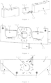
Figure 1 shows a front isometric view of a first embodiment of the present invention. -
Figure 2 shows a front isometric view of a first embodiment of the present invention without the plate. -
Figure 3 shows a front isometric view of the functional elements in a first embodiment of the present invention. -
Figure 4 shows a rear isometric view of a first embodiment of the present invention without the plate. -
Figure 5 shows a front isometric view of a first embodiment of the present invention without the base. -
Figure 6 shows a rear isometric view of a first embodiment of the present invention without the base. -
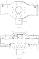
Figure 7 shows a front isometric view of a second embodiment of the present invention. -
Figure 8 shows a rear isometric view of a second embodiment of the present invention. -
Figure 9 shows a front isometric view of a second embodiment of the present invention without the plate. -
Figure 10 shows a rear isometric view of a second embodiment of the present invention without the base. - The elements and components of the equipment of the present invention and the elements necessary for the operation of the invention are marked in the figures:
- 1. chassis
- 1.1. base
- 1.1.1. base securing means
- 1.1.2. secondary base securing means 1.2. plate
- 1.2.1. plate securing means
- 1.2.2. secondary plate securing means
- 1.1. base
- 2. impact absorption means
- 3. functional element
- 3.1. weighing element
- 3.2. standard element
3.2.1. standard weight
- 4. electronics box
- The term "substantially" is understood to mean that the description of the shape or position of an element of the present invention is not mathematically or geometrically exact, but that the shape or position of an element of the present invention is recognized by an expert in the field as having generically or approximately the described shape or position.
- The terms "parallelepiped", "recto-rectangular", "semi-prismatic hexagonal", "circular", "prismatic hexagonal with two angles", "triangular", "L-shaped", and "inverted L-shaped" are understood to mean several possible shapes of embodiments of the components of the invention, which may also be functional in other shapes. Although not explicitly mentioned, the following shapes may be considered as possible alternative embodiments of the elements of the present invention when suitable for the purpose: circular, triangular, in parallelogram, in which rectangular, quadrilateral, rhombus, and trapezoidal are considered; pentagonal, hexagonal, heptagonal, octagonal, decagonal, in diamond and letter-shaped, as are the corresponding prism and semi-prism of all the previously described two-dimensional shapes, both regular and irregular, pyramidal and spherical, among others.
- The terms "centred", "vertical", "horizontal", "concentric", "inferior", "superior", "exterior", "frontal", "coaxial", "equidistant", and "parallel" are understood to mean several possible positions of embodiments of the components of the present invention, which may also be functional in other positions. Although not explicitly mentioned, the following positions may be considered as possible alternative embodiments of the elements of the present invention, when suitable for the purpose: horizontal, vertical, diagonal, coplanar, centred, perpendicular, tangential, over, under, superior, inferior, inner, outer, frontal, posterior, anterior, lateral, joined, separate, inside of and outside of, among others.
- The term "L-shaped" is understood to mean a shape of an element of the equipment of the present invention wherein, for an observer placed facing one of the sidewalls of the element, the element presents a shape substantially equal to the shape of the letter "L". Likewise, "inverted L-shaped" is understood to mean an "L" shape where the letter "L" has been inverted with respect to a horizontal axis passing through the centre of the letter.
- It should be noted that the terms above are used interchangeably in appropriate circumstances and that the embodiments of the invention described herein are capable of operating in shapes, forms, positions, and orientations other than those described or illustrated herein.
- As will be clear to a person skilled in the art, due to the nature of the invention, the present invention makes it possible to weigh any object or material used in science or industry, such as in the fields of, inter alia but not exclusively, the automotive industry, the aircraft industry, the shipbuilding industry, the space industry, metallurgy, the thermoformed plastics industry, raw material industries, the building materials industry, civil engineering, chemical and biochemical industry, the food industry, the pharmaceutical industry, the medical industry, among others, in industrial production lines, as well as in domestic use or in commercial establishments.
- As will be clear to an expert in the field, the application of the principles described here is not limited to the presented embodiments. Possible changes that may occur in the present invention, defined in number, remain within the scope of the present invention.
- Weighing equipment according to the principles described herein can comprise any number of the features shown. Likewise, the principles described herein can be applied to any weighing equipment.
- Additionally, although some embodiments present multiple new features, and as can be seen throughout this document, all features can be independent and it is not essential that all be used in a single embodiment.
- Additionally, the embodiments described herein are merely examples of the effect intended with the present invention, so other ways known from the state of the art to achieve the same technical effect are equally applicable for other embodiments.
- As will be clear to a person skilled in the art, the embodiments described herein can additionally feature any number of accessories known in the state of the art, such as, but not limited to, gyroscopes, goniometers, potentiometers, ammeters, gravimeters, speedometers, and accelerometers, among others.
- According to the figures, the present invention comprises a side-weighing equipment comprising a chassis (1) comprising two plates: a base (1.1) and a plate (1.2). Between the two plates are functional elements (3), mainly one or more weighing elements (3.1) and at least one standard element (3.2). The chassis (1) further comprises an electronics box (4) coupled to it.
- The chassis (1) can be made of any suitable material, such as, but not limited to, aluminium, steel, titanium, iron-, nickel-, copper- and/or tin-based materials, plastics, fibre composites, materials used in construction, among others, preferably aluminium.
- The base (1.1) serves to secure the chassis (1) to an external object, such as, namely, but not exclusively, industrial robot arms or heads, walls, motor vehicles, cranes, furniture, professional workbenches, hooks, mechanical hands or clamps, among others. Therefore, the base (1.1) can have any format suitable to its purpose. In a preferred embodiment, the base (1.1) has a substantially recto-rectangular parallelepipedic shape. In a second embodiment, in a position substantially centred on the upper and lower face of the base (1.1) two substantially semi-prismatic hexagonal-shaped additions were placed. In another embodiment, the base (1.1) has an "L" shape. In this embodiment, the base (1.1) has a vertical wall and a horizontal wall that correspond respectively to the vertical arm of the "L" and to the horizontal arm of the "L".
- The base (1.1) comprises at least one base securing means (1.1.1), preferably one, that allows the chassis (1) to be secured to any type of external support. In a preferred embodiment, the base securing means (1.1.1) is an opening substantially concentric with respect to the base (1.1), which preferably pierces the base (1.1) across its entire width. In this embodiment, the base securing means (1.1.1) may present any suitable shape for the purpose, preferably substantially circular, in which components are coupled that allow the securing of the base (1.1) to other external devices or support means such as, namely, but not exclusively, hooks, clamps, latches, grooves, protrusions, Velcro, adhesive, robot heads, among others. In other embodiments, the base securing means (1.1.1) may itself be equipment that allows the base (1.1) to be secured to external support means.
- In a preferred embodiment, the base (1.1) additionally comprises a set of secondary base securing means (1.1.2), which may be:
- holes into which means are inserted that, together with devices that are inserted into the base securing means (1.1.1), help to better secure the chassis (1) to a means of support; or
- means that, together with devices that are inserted into the base securing means (1.1.1), help to better secure the chassis (1) to a means of support.
- In a preferred embodiment, the base (1.1) additionally comprises further openings for placing impact absorption means (2). The function of the impact absorption means (2) is to prevent vibrations caused by the operation of other equipment that is close to the equipment of the present invention from causing changes in the measurement value obtained by the weighing equipment of the present invention. Additionally, the impact absorption means (2) allow for the absorption of shocks and vibrations caused by the movement of the equipment of the invention when it is, e.g., inserted and weighing, in an equipment or equipment component that is in motion. In a preferred embodiment, the impact absorbing means (2) are screws that are inserted into the plate (1.2). In this embodiment, the base (1.1) and the plate (2) have threaded holes, placed in a substantially coaxial and horizontal position, into which the screw is inserted. Thus, the impact absorption means (2) can also join the base (1.1) to the plate (1.2).
- The chassis (1) additionally comprises the plate (1.2) whose function is to obtain the weight of objects or materials by the equipment of the present invention. The plate (1.2) can have any shape suitable for this purpose, but must have an inverted "L" shape. Due to the inverted "L" shape of the plate (1.2), it has a horizontal top and a vertical wall. Preferably, the plate (1.2) has the same shape as the base (1.1). In a preferred embodiment, the plate (1.2) has a substantially recto-rectangular parallelepipedic shape. In a second embodiment, in a position substantially centred on the upper and lower face of the plate (1.2) additions with a substantially hexagonal semi-prismatic shape were placed. In another embodiment, the plate (1.2) has a substantially prismatic hexagonal shape with two right angles.
- The plate (1.2) comprises at least one plate securing means (1.2.1), preferably one, for securing objects or materials to the chassis (1) that enables the equipment of the present invention to perform weighing. In a preferred embodiment, the plate securing means (1.2.1) is an opening substantially concentric with respect to the vertical wall of the plate (1.2), which preferably pierces the vertical wall of the plate (1.2) across its entire width. In this embodiment, the plate securing means (1.2.1) may present any suitable shape for the purpose, preferably being substantially circular, in which the components that allow the securing of objects or materials to the chassis (1) are coupled, namely, but not exclusively, hooks, latches, clamps, grooved or protruding objects, Velcro, adhesive, among others. Additionally, another suitable means for attaching or grasping objects or materials, such as, notably but not exclusively, robot arms, mechanical grippers or hands, among others, may be secured to the plate securing means (1.2.1). In other embodiments, the plate securing means (1.2.1) may itself be a device that allows objects or materials to be secured to the chassis (1) .
- In a preferred embodiment, the plate (1.2) additionally comprises secondary plate securing means (1.2.2), which may be:
- holes into which means are inserted that, in conjunction with devices that are inserted into the plate securing means (1.2.1), help to better secure an object or material to the chassis (1); or
- means that, in conjunction with devices that are inserted into the plate securing means (1.2.1), help to better secure an object or material to the chassis (1).
- In a preferred embodiment, the plate (1.2) additionally comprises further openings for placing impact absorption means (2). In a preferred embodiment, the impact absorbing means (2) are screws that are inserted into the base (1.1). In this embodiment, the base (1.1) and the plate (1.2) have threaded holes, placed in a substantially coaxial and horizontal position, into which the screw is inserted. Thus, the impact absorption means (2) can also join the plate (1.2) to the base (1.1).
- As visible in
Figure 6 , in a preferred embodiment, the plate (1.2) has, on the inner side of the plate (1.2), substantially triangular additions at the angle formed by the wall and the top. Such additions provide greater rigidity to the structure of the plate (1.2). - In a preferred embodiment, the equipment of the present invention is applied to a robot used in industrial production lines, preferably from the automotive industry. Such a robot, like the one shown in patent document
EP0068770 , comprises an arm secured to a body by one end, with the other end comprising a wrist and a hand coupled to the wrist. In the present embodiment, the chassis (1) is the wrist of the robot. That is, the chassis (1) is secured to the robot arm by the base securing means (1.1.1) and preferably by the secondary base securing means (1.1.2) and is attached to the robot hand by the plate securing means (1.2.1) and preferably by the secondary plate securing means (1.2.2). In a preferred embodiment, this securing is accomplished by means of quick-change elements. In other embodiments, this securing is accomplished by any other type of securing element or securing system known in the state of the art. In a preferred embodiment, an electronic connection is made between the weighing equipment of the present invention and the robot, which allows power to be supplied to the weighing equipment and data to be exchanged between the weighing equipment and the robot. In this type of equipment, the scale of the present invention can weigh while the robot is in motion. - Inside the chassis (1) are the functional elements (3) of the weighing equipment of the present invention. More specifically, the functional elements (3) are located between the base (1.1) and the plate (1.2) . Because the plate (1.2) has an inverted "L" shape, the functional elements (3) are also under the top of the plate (1.2). In the embodiment wherein the base (1.1) has an "L" shape, the securing elements (3) are also on the bottom wall of the base (1.1). That is, the functional elements (3) are housed in the space between the upper wall of the base (1.1), the lower wall of the plate (1.2), the lower wall of the base (1.1), and the upper wall of the plate (2.1).
- The functional elements (3) comprise the weighing elements (3.1) and the standard elements (3.2). The weighing elements (3.1) are the components of the present invention responsible for measuring weight. There is at least one weighing element (3.1), preferably two. The bottom side of the top of the plate (1.2) is in contact with the top side of the weighing elements (3.1). In a preferred embodiment, the functional elements (3) are secured to the base (1.1) both by the vertical wall and, when present, by the horizontal wall. In a preferred embodiment, each weighing element (3.1) is additionally in contact on the front side with the vertical wall of the base (1.1) and on the rear side with the vertical wall of the plate (1.2). In a preferred embodiment, each weighing element (3.1) has a substantially recto-rectangular parallelepiped shape.
- The position of each weighing element (3.1) must be such that the force applied to the plate (1.2) is fully and evenly captured by the weighing elements (3.1). In embodiments where there are an odd number of weighing elements (3.1), one weighing element (3.1) must be positioned so that its centre is substantially coaxial with the centre of the plate (1.2) and the others, if there are more than one, must be substantially equidistant from the centre of the plate (1.2) and on opposite sides with respect to the centre of the plate (1.2). In embodiments where there is an even number of weighing elements (3.1), the two weighing elements (3.1) closest to the centre of the plate (1.2) must be positioned so that they are both substantially equidistant from the centre of the plate (1.2) and on opposite sides with respect to the centre of the plate (1.2). In embodiments wherein there are at least two weighing elements (3.1), the weighing elements (3.1) are all substantially equidistant from each other and in a substantially coaxial position with an axis parallel to the top and to the vertical wall of the plate (1.2) .
- Each weighing element (3.1) is any sensor that can measure the weight of objects. In a preferred embodiment, each weighing element (3.1) is a load cell weight sensor. In other embodiments, the weighing element (3.1) can be a single point weight sensor, S-type sensor, tension and compression sensor, or a piezoelectric sensor, among others.
- The equipment of the present invention comprises at least one standard element (3.2), preferably one. The at least one standard element (3.2) comprises, similarly to the weighing elements (3.1), a weight meter. However, the standard element (3.2) is not in contact with the plate (1.2), being secured to the base (1.1). The standard element (3.2) serves to establish a standard value with which the weighing equipment of the present invention can compare the weight being measured by the weighing elements (3.1). As such, the standard element (3.2) comprises a standard weight (3.2.1) that is secured to the upper side of the standard element weight gauge (3.2). Like the weighing elements (3.1), the standard element (3.2) comprises some kind of sensor to measure the weight of objects. In a preferred embodiment, each standard element (3.2) comprises a load cell weight sensor. In other embodiments, the standard element (3.2) can be a single point weight sensor, S-type sensor, tension and compression sensor, or a piezoelectric sensor, among others.
- In a preferred embodiment, the standard element (3.2) is in a position substantially centred with the chassis (1). Additionally, the standard weight (3.2.1) can have any suitable weight to be used as a standard. In a preferred embodiment, the standard weight (3.2.1) can have any weight between 0.01 kg and 10 kg, preferably between 0.1 kg and 5 kg, more preferably between 0.5 kg and 3 kg, more specifically between 1 kg and 2 kg.
- When an object or material is secured to the plate (1.2) on the outside of the vertical wall of the plate (1.2), it will exert a force on the plate (1.2) in the direction equal to the force of gravity, which is transmitted to the weighing elements (3.1) as they are in contact with the plate (1.2). However, in practical terms, weighing is carried out substantially vertically. The presence of the standard element (3.2) takes into account the deviations that exist in practice, preventing angular deviations in weighing from causing deviations in the measured value.
- Coupled to the chassis (1) is an electronics box (4) which comprises all the electronic elements necessary for the correct operation of the invention. The electronics box (4) may thus comprise any electronic element used for processing and sending information, such as, but not limited to, a processor, primary memory, secondary memory, an adapter for wireless connection to any known state-of-the-art wireless technology, visual or audible alarms, among others. Wireless connections include technologies such as, but not limited to, Ethernet, Wi-Fi, Bluetooth, Bluetooth Low Energy, Radio-Frequency Identification (RFID), Near Field Communication (NFC), Global System for Mobile Communication (GMS), Zigbee, 3G, 4G, 5G, Microwave, and Long Range (LoRa), among others, and others that may appear in the future. The wireless connection is important so that a user can easily observe on a fixed or mobile electronic device the weight measured by the weighing equipment of the present invention, as well as information about the technical operation, and can adjust properties of the weighing equipment of the present invention and take control of the device in which the weighing equipment of the present invention is comprised, if that is the case. Thus, the fixed or mobile electronic device can be selected, notably, but not exclusively, from among tablets, smartphones, laptops, desktop computers, control devices, joysticks, among others. In a preferred embodiment, the electronics box (4) is connected to the functional elements (3), receiving the information from the functional elements (3). The electronics box (4) may further preferably comprise electronic protection components, such as, notably, but not exclusively, short-circuit protection, radio-frequency protection, and undervoltage blocking, among others.
- To start weighing, the chassis (1) must first be secured to an external means of support. This is accomplished by securing the base (1.1) to an external means of support by the base securing means (1.1.1) and optionally by the secondary base securing means (1.1.2). Subsequently, an object or material is secured to the plate (1.2) by the plate securing means (1.2.1) and optionally by the secondary plate securing means (1.2.2) . Weighing is then performed by lifting the chassis (1). The weight of the object or material pulls down the plate (1.2), which puts pressure on at least one weighing element (3.1). A provisional value of the weighing is obtained, which is then compared with the value obtained by the standard element (3.2). Such a comparison normalizes any angular deviations that occur in the position of the chassis (1) and/or the plate (1.2). Although the chassis (1) is placed substantially vertically, it will never, for technically obvious reasons, be placed completely vertically. Thus, comparison with the standard element (3.2) adjusts these angular deviations, thus obtaining a definitive weighing value. This calculation work is performed by means of a processor that is present either in the electronics box (4) or in a remote control device of the weighing equipment of the present invention.
Claims (15)
- Side-weighing equipment comprising a chassis (1) comprising:- a base (1.1);- a plate (1.2) for obtaining the weight of objects or materials; and- functional elements (3) comprising at least one weighing element (3.1);wherein:- the functional elements (3) additionally comprise at least one standard element (3.2);- the plate (1.2) presents an inverted "L" shape and comprises a horizontal top and a vertical wall, the horizontal top resting on the top side of at least one weighing element (3.1); and- the at least one weighing element (3.1) and the at least one standard element (3.2) being secured to the base (1.1).
- Equipment according to the preceding claim, wherein the chassis (1) additionally comprises sock-absorption means (2) inserted into the plate (1.2) and the base (1.1).
- Equipment according to any of the preceding claims, wherein the base (1.1) comprises at least one base securing means (1.1.1).
- Equipment according to any of the preceding claims, wherein the base securing means (1.1.1) is an opening for coupling the components for attaching the chassis (1) to external support means.
- Equipment according to any of the preceding claims, wherein the base (1.1) additionally comprises secondary base securing means (1.1.2).
- Equipment according to any of the preceding claims, wherein the plate (1.2) comprises at least one plate securing means (1.2.1) placed on the vertical wall of the plate (1.2).
- Equipment according to the preceding claim, wherein the plate securing means (1.2.1) is an opening for coupling components that secure objects or materials to the chassis (1).
- Equipment according to any of the preceding claims, wherein the plate (1.2) additionally comprises secondary plate securing means (1.2.2).
- Equipment according to any of the preceding claims, wherein the plate (1.2) additionally comprises, on the inner side of the plate (1.2), substantially triangular additions at the angle formed by the wall and the top.
- Equipment according to any of the preceding claims, wherein the impact absorption means (2) are screws.
- Equipment according to the preceding claim, wherein the impact absorption means (2) join the base (1.1) to the plate (1.2) and the plate (1.2) to the base (1.1).
- Equipment according to any of the preceding claims, characterized by comprising two weighing elements (3.1) secured to the base (1.1), both by the vertical wall and, when present, by the horizontal wall, and additionally being in contact, on the front side, with the vertical wall of the base (1.1) and, on the rear side, with the vertical wall of the plate (1.2).
- Equipment according to any of the preceding claims, wherein the at least one standard element (3.2) is a standard weight (3.2.1).
- Equipment according to any of the preceding claims, wherein the weighing elements (3.1) and the standard elements (3.2) are load cell weight sensors, single point weight sensors, S-type sensors, tension and compression sensors, or piezoelectric sensors.
- Use of the equipment claimed in claims 1 to 14 in industrial production lines.
Applications Claiming Priority (2)
| Application Number | Priority Date | Filing Date | Title |
|---|---|---|---|
| PT11797622 | 2022-05-12 | ||
| PT117992A PT117992A (en) | 2022-05-23 | 2022-05-23 | SIDE WEIGHING EQUIPMENT |
Publications (3)
| Publication Number | Publication Date |
|---|---|
| EP4276424A1 true EP4276424A1 (en) | 2023-11-15 |
| EP4276424B1 EP4276424B1 (en) | 2025-07-09 |
| EP4276424C0 EP4276424C0 (en) | 2025-07-09 |
Family
ID=88294954
Family Applications (1)
| Application Number | Title | Priority Date | Filing Date |
|---|---|---|---|
| EP22175557.2A Active EP4276424B1 (en) | 2022-05-12 | 2022-05-25 | Lateral weighing device |
Country Status (1)
| Country | Link |
|---|---|
| EP (1) | EP4276424B1 (en) |
Citations (4)
| Publication number | Priority date | Publication date | Assignee | Title |
|---|---|---|---|---|
| EP0068770A2 (en) | 1981-06-29 | 1983-01-05 | Fanuc Ltd. | An industrial robot |
| KR20020029354A (en) | 2002-03-11 | 2002-04-18 | 정광용 | a scale movable |
| CN103090944A (en) | 2013-01-11 | 2013-05-08 | 浙江南洋传感器制造有限公司 | Integrated crane scale |
| US20130319072A1 (en) * | 2011-02-08 | 2013-12-05 | Sartorius Weighing Technology Gmbh | Load cell and method for adjusting a load cell |
-
2022
- 2022-05-25 EP EP22175557.2A patent/EP4276424B1/en active Active
Patent Citations (4)
| Publication number | Priority date | Publication date | Assignee | Title |
|---|---|---|---|---|
| EP0068770A2 (en) | 1981-06-29 | 1983-01-05 | Fanuc Ltd. | An industrial robot |
| KR20020029354A (en) | 2002-03-11 | 2002-04-18 | 정광용 | a scale movable |
| US20130319072A1 (en) * | 2011-02-08 | 2013-12-05 | Sartorius Weighing Technology Gmbh | Load cell and method for adjusting a load cell |
| CN103090944A (en) | 2013-01-11 | 2013-05-08 | 浙江南洋传感器制造有限公司 | Integrated crane scale |
Also Published As
| Publication number | Publication date |
|---|---|
| EP4276424B1 (en) | 2025-07-09 |
| EP4276424C0 (en) | 2025-07-09 |
Similar Documents
| Publication | Publication Date | Title |
|---|---|---|
| US9239227B1 (en) | 3D laser measuring device | |
| JP2018531201A (en) | Material management system and method | |
| JP2018531201A6 (en) | Material management system and method | |
| WO2014108033A1 (en) | Hook deviation angle detection and monitoring apparatus and crane | |
| WO2011090887A1 (en) | Coordinate measurement device | |
| KR101601094B1 (en) | Measuring System of Inertia and Mass Center | |
| EP4276424B1 (en) | Lateral weighing device | |
| CN203229002U (en) | GPS weighing pallet | |
| CN102620887A (en) | Device for testing quality characteristic of component | |
| JP7141094B2 (en) | device with an electronic compass | |
| CN204479242U (en) | A kind of adjustable propeller static balance testing device | |
| CN104016232B (en) | Dynamic weighing mechanism for lifting device | |
| JP5342399B2 (en) | Hanging scale | |
| JP2002277310A (en) | Electronic suspension scale | |
| KR102665769B1 (en) | electronic strut monitor | |
| EP4286803A2 (en) | Intelligent digital load cell transducer | |
| CN216348555U (en) | Pillar angle detection device and system | |
| RU69990U1 (en) | CRANE SCALES | |
| CN215974635U (en) | Hoisting machinery amplitude monitoring system | |
| CN221006409U (en) | Wharf container monitoring system | |
| WO2022016952A1 (en) | Device placement apparatus | |
| CN114526801B (en) | Quick weighing device for electronic hanging scale | |
| CN218762571U (en) | Posture display device | |
| CN113526337A (en) | A hydraulic weighing hook device | |
| CN224080989U (en) | Mine engineering measurement lifting hammer |
Legal Events
| Date | Code | Title | Description |
|---|---|---|---|
| PUAI | Public reference made under article 153(3) epc to a published international application that has entered the european phase |
Free format text: ORIGINAL CODE: 0009012 |
|
| STAA | Information on the status of an ep patent application or granted ep patent |
Free format text: STATUS: THE APPLICATION HAS BEEN PUBLISHED |
|
| AK | Designated contracting states |
Kind code of ref document: A1 Designated state(s): AL AT BE BG CH CY CZ DE DK EE ES FI FR GB GR HR HU IE IS IT LI LT LU LV MC MK MT NL NO PL PT RO RS SE SI SK SM TR |
|
| STAA | Information on the status of an ep patent application or granted ep patent |
Free format text: STATUS: REQUEST FOR EXAMINATION WAS MADE |
|
| 17P | Request for examination filed |
Effective date: 20240515 |
|
| RBV | Designated contracting states (corrected) |
Designated state(s): AL AT BE BG CH CY CZ DE DK EE ES FI FR GB GR HR HU IE IS IT LI LT LU LV MC MK MT NL NO PL PT RO RS SE SI SK SM TR |
|
| GRAP | Despatch of communication of intention to grant a patent |
Free format text: ORIGINAL CODE: EPIDOSNIGR1 |
|
| STAA | Information on the status of an ep patent application or granted ep patent |
Free format text: STATUS: GRANT OF PATENT IS INTENDED |
|
| INTG | Intention to grant announced |
Effective date: 20250305 |
|
| GRAS | Grant fee paid |
Free format text: ORIGINAL CODE: EPIDOSNIGR3 |
|
| GRAA | (expected) grant |
Free format text: ORIGINAL CODE: 0009210 |
|
| STAA | Information on the status of an ep patent application or granted ep patent |
Free format text: STATUS: THE PATENT HAS BEEN GRANTED |
|
| AK | Designated contracting states |
Kind code of ref document: B1 Designated state(s): AL AT BE BG CH CY CZ DE DK EE ES FI FR GB GR HR HU IE IS IT LI LT LU LV MC MK MT NL NO PL PT RO RS SE SI SK SM TR |
|
| REG | Reference to a national code |
Ref country code: GB Ref legal event code: FG4D |
|
| REG | Reference to a national code |
Ref country code: CH Ref legal event code: EP |
|
| REG | Reference to a national code |
Ref country code: IE Ref legal event code: FG4D |
|
| REG | Reference to a national code |
Ref country code: DE Ref legal event code: R096 Ref document number: 602022017198 Country of ref document: DE |
|
| U01 | Request for unitary effect filed |
Effective date: 20250808 |
|
| U07 | Unitary effect registered |
Designated state(s): AT BE BG DE DK EE FI FR IT LT LU LV MT NL PT RO SE SI Effective date: 20250821 |
|
| PG25 | Lapsed in a contracting state [announced via postgrant information from national office to epo] |
Ref country code: IS Free format text: LAPSE BECAUSE OF FAILURE TO SUBMIT A TRANSLATION OF THE DESCRIPTION OR TO PAY THE FEE WITHIN THE PRESCRIBED TIME-LIMIT Effective date: 20251109 |
|
| PG25 | Lapsed in a contracting state [announced via postgrant information from national office to epo] |
Ref country code: NO Free format text: LAPSE BECAUSE OF FAILURE TO SUBMIT A TRANSLATION OF THE DESCRIPTION OR TO PAY THE FEE WITHIN THE PRESCRIBED TIME-LIMIT Effective date: 20251009 |
|
| PG25 | Lapsed in a contracting state [announced via postgrant information from national office to epo] |
Ref country code: HR Free format text: LAPSE BECAUSE OF FAILURE TO SUBMIT A TRANSLATION OF THE DESCRIPTION OR TO PAY THE FEE WITHIN THE PRESCRIBED TIME-LIMIT Effective date: 20250709 |
|
| PG25 | Lapsed in a contracting state [announced via postgrant information from national office to epo] |
Ref country code: PL Free format text: LAPSE BECAUSE OF FAILURE TO SUBMIT A TRANSLATION OF THE DESCRIPTION OR TO PAY THE FEE WITHIN THE PRESCRIBED TIME-LIMIT Effective date: 20250709 |
|
| PG25 | Lapsed in a contracting state [announced via postgrant information from national office to epo] |
Ref country code: RS Free format text: LAPSE BECAUSE OF FAILURE TO SUBMIT A TRANSLATION OF THE DESCRIPTION OR TO PAY THE FEE WITHIN THE PRESCRIBED TIME-LIMIT Effective date: 20251009 |
|
| PG25 | Lapsed in a contracting state [announced via postgrant information from national office to epo] |
Ref country code: ES Free format text: LAPSE BECAUSE OF FAILURE TO SUBMIT A TRANSLATION OF THE DESCRIPTION OR TO PAY THE FEE WITHIN THE PRESCRIBED TIME-LIMIT Effective date: 20250709 |
|
| PG25 | Lapsed in a contracting state [announced via postgrant information from national office to epo] |
Ref country code: SM Free format text: LAPSE BECAUSE OF FAILURE TO SUBMIT A TRANSLATION OF THE DESCRIPTION OR TO PAY THE FEE WITHIN THE PRESCRIBED TIME-LIMIT Effective date: 20250709 |
|
| PG25 | Lapsed in a contracting state [announced via postgrant information from national office to epo] |
Ref country code: CZ Free format text: LAPSE BECAUSE OF FAILURE TO SUBMIT A TRANSLATION OF THE DESCRIPTION OR TO PAY THE FEE WITHIN THE PRESCRIBED TIME-LIMIT Effective date: 20250709 |
|
| PG25 | Lapsed in a contracting state [announced via postgrant information from national office to epo] |
Ref country code: SK Free format text: LAPSE BECAUSE OF FAILURE TO SUBMIT A TRANSLATION OF THE DESCRIPTION OR TO PAY THE FEE WITHIN THE PRESCRIBED TIME-LIMIT Effective date: 20250709 |
|
| PLBE | No opposition filed within time limit |
Free format text: ORIGINAL CODE: 0009261 |
|
| STAA | Information on the status of an ep patent application or granted ep patent |
Free format text: STATUS: NO OPPOSITION FILED WITHIN TIME LIMIT |