EP4276419A1 - Portable device, optical fiber sensing system, and analysis method - Google Patents
Portable device, optical fiber sensing system, and analysis method Download PDFInfo
- Publication number
- EP4276419A1 EP4276419A1 EP21933135.2A EP21933135A EP4276419A1 EP 4276419 A1 EP4276419 A1 EP 4276419A1 EP 21933135 A EP21933135 A EP 21933135A EP 4276419 A1 EP4276419 A1 EP 4276419A1
- Authority
- EP
- European Patent Office
- Prior art keywords
- analysis
- portable device
- sensing
- optical fiber
- analysis processing
- Prior art date
- Legal status (The legal status is an assumption and is not a legal conclusion. Google has not performed a legal analysis and makes no representation as to the accuracy of the status listed.)
- Withdrawn
Links
- 238000004458 analytical method Methods 0.000 title claims abstract description 261
- 239000013307 optical fiber Substances 0.000 title claims abstract description 126
- 238000004891 communication Methods 0.000 claims abstract description 77
- 230000005856 abnormality Effects 0.000 claims description 3
- 230000001413 cellular effect Effects 0.000 claims description 3
- 238000013473 artificial intelligence Methods 0.000 description 14
- 238000010586 diagram Methods 0.000 description 11
- 238000009529 body temperature measurement Methods 0.000 description 8
- 230000000694 effects Effects 0.000 description 8
- 230000006870 function Effects 0.000 description 7
- 238000000034 method Methods 0.000 description 5
- 101001059930 Drosophila melanogaster Transcription factor kayak, isoforms A/B/F Proteins 0.000 description 4
- 101001059931 Drosophila melanogaster Transcription factor kayak, isoforms D/sro Proteins 0.000 description 4
- 239000013256 coordination polymer Substances 0.000 description 4
- 230000002159 abnormal effect Effects 0.000 description 3
- 238000010801 machine learning Methods 0.000 description 2
- 238000005259 measurement Methods 0.000 description 2
- 238000007781 pre-processing Methods 0.000 description 2
- 238000001069 Raman spectroscopy Methods 0.000 description 1
- 238000001514 detection method Methods 0.000 description 1
- 239000000835 fiber Substances 0.000 description 1
- 230000007774 longterm Effects 0.000 description 1
- 230000003287 optical effect Effects 0.000 description 1
- 230000004044 response Effects 0.000 description 1
- 230000009466 transformation Effects 0.000 description 1
Images




Classifications
-
- G—PHYSICS
- G01—MEASURING; TESTING
- G01D—MEASURING NOT SPECIALLY ADAPTED FOR A SPECIFIC VARIABLE; ARRANGEMENTS FOR MEASURING TWO OR MORE VARIABLES NOT COVERED IN A SINGLE OTHER SUBCLASS; TARIFF METERING APPARATUS; MEASURING OR TESTING NOT OTHERWISE PROVIDED FOR
- G01D5/00—Mechanical means for transferring the output of a sensing member; Means for converting the output of a sensing member to another variable where the form or nature of the sensing member does not constrain the means for converting; Transducers not specially adapted for a specific variable
- G01D5/26—Mechanical means for transferring the output of a sensing member; Means for converting the output of a sensing member to another variable where the form or nature of the sensing member does not constrain the means for converting; Transducers not specially adapted for a specific variable characterised by optical transfer means, i.e. using infrared, visible, or ultraviolet light
- G01D5/32—Mechanical means for transferring the output of a sensing member; Means for converting the output of a sensing member to another variable where the form or nature of the sensing member does not constrain the means for converting; Transducers not specially adapted for a specific variable characterised by optical transfer means, i.e. using infrared, visible, or ultraviolet light with attenuation or whole or partial obturation of beams of light
- G01D5/34—Mechanical means for transferring the output of a sensing member; Means for converting the output of a sensing member to another variable where the form or nature of the sensing member does not constrain the means for converting; Transducers not specially adapted for a specific variable characterised by optical transfer means, i.e. using infrared, visible, or ultraviolet light with attenuation or whole or partial obturation of beams of light the beams of light being detected by photocells
- G01D5/353—Mechanical means for transferring the output of a sensing member; Means for converting the output of a sensing member to another variable where the form or nature of the sensing member does not constrain the means for converting; Transducers not specially adapted for a specific variable characterised by optical transfer means, i.e. using infrared, visible, or ultraviolet light with attenuation or whole or partial obturation of beams of light the beams of light being detected by photocells influencing the transmission properties of an optical fibre
Definitions
- the present invention relates to a portable device and the like.
- PTL 1 discloses an optical fiber distributed temperature measurement device measuring a temperature distribution by optical fiber sensing (see paragraphs [0002] to [0005], [0030], and [0031], Figs. 2 and 4 , and the like in PTL 1).
- the optical fiber distributed temperature measurement device described in PTL 1 includes an electrical signal control processing block, an optical system block, a reference optical fiber block, and a power supply block (see paragraphs [0030] and [0031], Fig. 2 , and the like in PTL 1).
- the individual blocks are housed in housing cases.
- the optical fiber distributed temperature measurement device is constituted of the housing cases being connected to one another (see abstract, Fig. 1 , and the like in PTL 1).
- the optical fiber distributed temperature measurement device described in PTL 1 includes an electrical signal control processing block, but does not include a block for communicating with an external system.
- AI artificial intelligence
- an object of the present invention is to provide a portable device and the like that are able to easily achieve an analysis in cooperation with an external system on data acquired by optical fiber sensing.
- a portable device includes: a sensing means for executing optical fiber sensing using an optical fiber cable; an analysis means for executing primary analysis processing on sensing data acquired by the optical fiber sensing; a communication means for transmitting, to an external analysis means for executing secondary analysis processing based on a result of the primary analysis processing outside the portable device, data including a result of the primary analysis processing; and a housing accommodating the sensing means, the analysis means, and the communication means.
- An analysis method includes, by a portable device: executing optical fiber sensing using an optical fiber cable; executing primary analysis processing on sensing data acquired by the optical fiber sensing; and transmitting, to an external analysis means for executing secondary analysis processing based on a result of the primary analysis processing outside the portable device, data including a result of the primary analysis processing.
- the present invention is able to easily achieve an analysis in cooperation with an external system on data acquired by optical fiber sensing.
- Fig. 1 is a block diagram illustrating a main portion of an optical fiber sensing system according to a first example embodiment.
- Fig. 2 is a block diagram illustrating a main portion of a portable device and an analysis system according to the first example embodiment. The optical fiber sensing system according to the first example embodiment will be described with reference to Figs. 1 and 2 .
- an optical fiber sensing system 100 includes an optical fiber cable 1, a portable device 2, an analysis system 3, an output system 4, and a control system 5.
- the portable device 2 can freely communicate with the analysis system 3 via a network NW.
- the analysis system 3 can freely communicate with the output system 4 via the network NW.
- the control system 5 can freely communicate with each of the portable device 2, the analysis system 3, and the output system 4 via the network NW.
- the portable device 2 includes a sensing unit 11, an analysis unit 12, and a communication unit 13.
- the communication unit 13 is provided in the analysis unit 12.
- the portable device 2 includes a power supply circuit 14.
- the analysis system 3 includes an AI engine 21.
- the optical fiber cable 1 can be used in optical fiber sensing. Specifically, for example, the optical fiber cable 1 can be used in detection of vibration, sound, or temperature by distributed optical fiber sensing (distributed fiber optic sensing, DFOS).
- distributed optical fiber sensing distributed fiber optic sensing, DFOS
- data acquired by executing optical fiber sensing using the optical fiber cable 1 may be collectively referred to as "sensing data”.
- the sensing unit 11 acquires sensing data by executing optical fiber sensing (more specifically, DFOS) using the optical fiber cable 1.
- the sensing unit 11 is configured by, for example, a distributed vibration sensing (DVS) device or a distributed acoustic sensing (DAS) device.
- the sensing data acquired by the sensing unit 11 are a distribution in a longitudinal direction of the optical fiber cable 1, and include a distribution of vibration intensity or sound intensity for each frequency component.
- the sensing unit 11 is configured by a distributed temperature sensing (DTS) device.
- DTS distributed temperature sensing
- the sensing data acquired by the sensing unit 11 are a distribution in a longitudinal direction of the optical fiber cable 1, and include a distribution of a relative value (for example, a ratio of intensity of Raman scattered light) associated with temperature.
- the analysis unit 12 executes predetermined analysis processing (hereinafter, will be referred to as "primary analysis processing") on sensing data acquired by the sensing unit 11.
- the primary analysis processing includes, for example, processing (so-called “lat-long") of determining a position coordinate associated with the acquired sensing data.
- the primary analysis processing includes processing of detecting, using the acquired sensing data, occurrence of an abnormality (occurrence of abnormal vibration, occurrence of abnormal sound, occurrence of abnormal temperature change, or the like) around the optical fiber cable 1.
- the primary analysis processing includes both the pieces of processing.
- Various kinds of known techniques can be used in the pieces of processing. Detailed description of the techniques will be omitted.
- the communication unit 13 of the analysis unit 12 can freely communicate with the analysis system 3.
- the communication unit 13 transmits, to the analysis system 3, data (hereinafter, may be referred to as "primary analysis data") including a result of primary analysis processing executed by the analysis unit 12.
- the analysis unit 12 is configured by, for example, a serve device.
- the server device uses, for example, an on-vehicle computer or a rack mount server.
- the communication unit 13 is configured by, for example, at least one of a wireless communication module and a wired communication module provided in the server device.
- the wireless communication module uses, for example, a 3rd generation (3G) module, a long term evolution (LTE) module, a 5th generation (5G) module, or a wireless local area network (LAN) module.
- the wired communication module uses, for example, a wired LAN module. That is, the communication unit 13 uses, for example, at least one of a cellular module and a LAN module.
- the power supply circuit 14 supplies electrical power for operation to each of the sensing unit 11 and the analysis unit 12 (including the communication unit 13), by using electrical power supplied from an external power supply PS. That is, the sensing unit 11 executes optical fiber sensing as described above, by using electrical power supplied from the power supply circuit 14. Further, the analysis unit 12 executes primary analysis processing as described above, by using electrical power supplied from the power supply circuit 14. Further, the communication unit 13 of the analysis unit 12 transmits primary analysis data to the analysis system 3 as described above, by using electrical power supplied from the power supply circuit 14.
- the external power supply PS is configured by, for example, an AC power supply for home use or for commercial use.
- the power supply circuit 14 is configured by, for example, a power supply module including an AC-DC converter and a DC-DC converter for transformation (more specifically, for step-down).
- the analysis system 3 receives primary analysis data transmitted from the portable device 2.
- the analysis system 3 executes another predetermined analysis processing (hereinafter, will be referred to as "secondary analysis processing") on the received primary analysis data. That is, the secondary analysis processing is processing based on a result of primary analysis processing in the portable device 2.
- the primary analysis processing in the portable device 2 is processing equivalent to preprocessing on the secondary analysis processing in the analysis system 3.
- the analysis system 3 is configured by, for example, a cloud server.
- the secondary analysis processing includes, for example, processing of generating data (hereinafter, will be referred to as "value-added data") having improved value compared with the above received primary analysis data, by processing the primary analysis data.
- the "value” is, for example, value for a customer of a service provided by using the optical fiber sensing system 100.
- the secondary analysis processing may use the dedicated AI engine 21.
- the AI engine 21 uses, for example, a learned model generated by machine learning.
- the analysis system 3 inputs the above received primary analysis data to the AI engine 21.
- the AI engine 21 outputs value-added data in response to the input, based on a result of machine learning. In this way, value-added data are generated.
- the analysis system 3 transmits the generated value-added data to the output system 4.
- the output system 4 receives the transmitted value-added data.
- the output system 4 outputs the received value-added data.
- value-added data are provided to the above customer.
- value-added data are output to another system (not illustrated).
- the output system 4 is configured by, for example, another cloud server.
- the output system 4 may output value-added data by displaying, using a graphical user interface (GUI), an image associated with value-added data.
- GUI graphical user interface
- API application programming interface
- the communication unit 13 can freely communicate with the analysis system 3.
- the communication unit 13 can freely communicate with the control system 5.
- the control system 5 controls an operation of each of the sensing unit 11 and the analysis unit 12, by communicating with the communication unit 13. That is, the sensing unit 11 executes optical fiber sensing as described above, under control of the control system 5. Further, the analysis unit 12 executes primary analysis processing as described above, under control of the control system 5. Further, the communication unit 13 of the analysis unit 12 transmits primary analysis data to the analysis system 3 as described above, under control of the control system 5.
- the control system 5 is configured by, for example, another cloud server.
- the control system 5 transmits, to the portable device 2, a signal (hereinafter, will be referred to as a "first control signal”) for controlling an operation of the sensing unit 11 and a signal (hereinafter, will be referred to as a "second control signal”) for controlling an operation of the analysis unit 12.
- the communication unit 13 receives the transmitted first control signal and the second control signal.
- the communication unit 13 outputs the received first control signal and the second control signal to the analysis unit 12.
- the analysis unit 12 executes primary analysis processing, based on the output second control signal, and outputs the output first control signal to the sensing unit 11.
- the sensing unit 11 executes optical fiber sensing, based on the output first control signal.
- control system 5 may control an operation of the analysis system 3, by communicating with the analysis system 3. That is, the analysis system 3 may execute secondary analysis processing as described above, under control of the control system 5. Further, the analysis system 3 may transmit value-added data to the output system 4 as described above, under control of the control system 5.
- control system 5 may output an operation of the output system 4, by communicating with the output system 4. That is, the output system 4 may output value-added data as described above, under control of the control system 5.
- control system 5 may control an overall operation of the optical fiber sensing system 100.
- the sensing unit 11 may be referred to as a "sensing means".
- the analysis unit 12 may be referred to as an "analysis means”.
- the communication unit 13 may be referred to as a "communication means”.
- the analysis system 3 may be referred to as an “external analysis means”.
- the control system 5 may be referred to as an "external control means”.
- the sensing unit 11 is configured by, for example, a DVS device, a DAS device, or a DTS device.
- the analysis unit 12 is configured by, for example, a server device.
- the communication unit 13 is configured by, for example, a communication module provided in a server device.
- the power supply circuit 14 is configured by, for example, a power supply module.
- the portable device 2 includes the housing 15 accommodating the sensing unit 11, the analysis unit 12 (including the communication unit 13), and the power supply circuit 14, as illustrated in Fig. 3 .
- the sensing unit 11, the analysis unit 12, and the power supply circuit 14 are fixed, inside the housing 15, to the housing 15 by using a not-illustrated screw or the like.
- the housing 15 may include a not-illustrated handle. Thereby, the portable device 2 can be easily carried by a human hand.
- the communication unit 13 (not illustrated in Fig. 3 ) of the analysis unit 12 uses both of a wireless communication module and a wired communication module.
- the communication unit 13 can freely communicate with an external system by using a radio wave RW, and can freely communicate with an external system by using a wired communication cable CC1 connected to a wired communication port CP.
- the radio wave RW is, for example, a radio wave for 3G communication, LTE communication, 5G communication, or wireless LAN communication.
- the wired communication port CP is, for example, a wired LAN port.
- the wired communication cable CC1 is, for example, a LAN cable.
- the communication unit 13 communicates with the analysis system 3 by using the radio wave RW, and communicates with the control system 5 by using the wired communication cable CC1 connected to the wired communication port CP.
- the wired communication port CP may be a wired communication port for control.
- the wired communication cable CC1 may be a wired communication cable for control.
- the sensing unit 11 and the analysis unit 12 are connected to each other by another wired communication cable CC2.
- the sensing unit 11 and the analysis unit 12 can freely communicate with each other.
- the sensing unit 11 can output sensing data to the analysis unit 12.
- the analysis unit 12 can output a first control signal to the sensing unit 11.
- the power supply circuit 14 supplies electrical power for operation to each of the sensing unit 11 and the analysis unit 12, by using electrical power supplied from the external power supply PS (not illustrated in Fig. 3 ).
- the power supply circuit 14 is electrically connected to the external power supply PS by an AC power supply cable PC1.
- the sensing unit 11 is electrically connected to the power supply circuit 14 by a DC power supply cable PC2.
- the analysis unit 12 is electrically connected to the power supply circuit 14 by another DC power supply cable PC3.
- a power supply circuit for the sensing unit 11 and a power supply circuit for the analysis unit 12 are provided separately from each other inside the housing 15, it is required that two AC power supply cables be connected to the portable device 2.
- the number of AC power supply cables PC1 to be connected to the portable device 2 can be reduced to one, by providing the power supply circuit 14 shared by the sensing unit 11 and the analysis unit 12. This can facilitate handling of the portable device 2.
- the sensing unit 11 executes optical fiber sensing (more specifically, DFOS) using the optical fiber cable 1 (Step ST1). Thereby, sensing data are acquired. Then, the analysis unit 12 executes primary analysis processing on the sensing data acquired in Step ST1 (Step ST2). A specific example of the primary analysis processing is as described already. Thus, repeated description will be omitted. Then, the communication unit 13 of the analysis unit 12 transmits, to the analysis system 3, data (that is, primary analysis data) including a result of the primary analysis processing in Step ST2 (Step ST3).
- data that is, primary analysis data
- the optical fiber sensing system 100' includes an optical fiber cable 1', an analysis system 3', an output system 4', and a control system 5'.
- the optical fiber cable 1', the analysis system 3', the output system 4', and the control system 5' are similar to the optical fiber cable 1, the analysis system 3, the output system 4, and the control system 5, in the optical fiber sensing system 100.
- the optical fiber sensing system 100' includes a sensing device 11' and an analysis device 12', instead of the portable device 2 in the optical fiber sensing system 100.
- the analysis device 12' can freely communicate with the analysis system 3' via a network NW'.
- the sensing device 11' includes a function similar to a function included in the sensing unit 11 of the portable device 2 in the optical fiber sensing system 100. That is, the sensing device 11' is configured by, for example, a DVS device, a DAS device, or a DTS device.
- the analysis device 12' includes a function similar to a function included in the analysis unit 12 (including the communication unit 13) of the portable device 2 in the optical fiber sensing system 100. That is, the analysis device 12' is configured by, for example, a server device.
- the server device is equivalent to an edge computer for a cloud network including the analysis system 3', the output system 4', and the control system 5'.
- an operation of laying the optical fiber cable 1' and an operation of installing the sensing device 11' are required in order to achieve optical fiber sensing. That is, an operation of bringing the sensing device 11' to a spot where one end of the optical fiber cable 1' is arranged and connecting the one end of the optical fiber cable 1' to the sensing device 11'.
- an operation of installing the analysis device 12' is required in order to achieve an analysis (including primary analysis processing and secondary analysis processing) of sensing data. That is, an operation of preparing an edge computer for primary analysis processing and for communication with the analysis system 3' is required.
- a function of executing optical fiber sensing, a function of executing primary analysis processing, and a function of transmitting primary analysis data are achieved by the portable device 2.
- an operation of preparing an edge computer equivalent to the analysis device 12' is unnecessary, upon achieving an analysis (including primary analysis processing and secondary analysis processing) of sensing data. This can easily achieve an analysis of sensing data, compared with the optical fiber sensing system 100'.
- the optical fiber distributed temperature measurement device described in PTL 1 includes an electrical signal control processing block, but does not include a block for communicating with an external system.
- an electrical signal control processing block but does not include a block for communicating with an external system.
- the portable device 2 includes the communication unit 13 transmitting primary analysis data to the analysis system 3.
- an analysis including primary analysis processing and secondary analysis processing
- an analysis in cooperation with an external system can be easily achieved, compared with when the optical fiber temperature distribution measurement device described in PTL 1 is used.
- an analysis using the dedicated AI engine 21 in an external system can be easily achieved.
- each of the sensing unit 11 and the analysis unit 12 may be unitized, and individual units may be configured detachably to the housing 15. Further, there may be provided a structure in which, when individual units are accommodated in the housing 15, the accommodated units are electrically connected to the power supply circuit 14.
- a selected sensing unit 11 among a plurality of types of sensing units 11 prepared in advance may be mounted.
- the plurality of types of sensing units 11 may execute, for example, sensing (for example, DVS, DAS, or DTS) different from each other.
- a selected analysis unit 12 among a plurality of types of analysis units 12 prepared in advance may be mounted.
- the plurality of types of analysis units 12 may execute, for example, primary analysis processing of different contents from each other.
- the portable device 2 may include a battery 16 instead of the power supply circuit 14.
- the battery 16 supplies electrical power for operation to each of the sensing unit 11 and the analysis unit 12 (including the communication unit 13).
- the battery 16 is accommodated in the housing 15. Use of the battery 16 can reduce the number of AC power supply cables to be connected to the portable device 2 to zero. This can further facilitate handling of the portable device 2.
- the optical fiber sensing system 100 may include the portable device 2 and the analysis system 3. In other words, a main portion of the optical fiber sensing system 100 may be configured by the portable device 2 and the analysis system 3. In this case, the output system 4 and the control system 5 may be provided outside the optical fiber sensing system 100.
- the portable device 2 may include the sensing unit 11, the analysis unit 12, the communication unit 13, and the housing 15. In other words, a main portion of the portable device 2 may be configured by the sensing unit 11, the analysis unit 12, the communication unit 13, and the housing 15. In this case, the power supply circuit 14 or the battery 16 may be provided outside the portable device 2.
- the sensing unit 11 of the portable device 2 executes optical fiber sensing using the optical fiber cable 1 (not illustrated in Figs. 7 and 8 ).
- the analysis unit 12 of the portable device 2 executes primary analysis processing on sensing data acquired by the optical fiber sensing.
- the communication unit 13 of the portable device 2 transmits, to the analysis system 3 executing secondary analysis processing based on a result of the primary analysis processing outside the portable device 2, data (primary analysis data) including a result of the primary analysis processing.
- Fig. 9 is a block diagram illustrating a main portion of an optical fiber sensing system according to a second example embodiment.
- the optical fiber sensing system according to the second example embodiment will be described with reference to Fig. 9 .
- an optical fiber sensing system 100a includes N optical fiber cables 1_1 to 1_N and M portable devices 2_1 to 2_M.
- N and M are an integer equal to or more than 2.
- Each of the portable devices 2_1 to 2_M can freely communicate with an analysis system 3 via a network NW.
- a control system 5 can freely communicate with each of the portable devices 2_1 to 2_M, the analysis system 3, and an output system 4 via the network NW.
- the individual optical fiber cable 1 in the optical fiber sensing system 100a is similar to the optical fiber cable 1 in the optical fiber sensing system 100 according to the first example embodiment. Further, the individual portable device 2 in the optical fiber sensing system 100a is similar to the portable device 2 in the optical fiber sensing system 100 according to the first example embodiment.
- a sensing unit 11 (not illustrated in Fig. 9 ) of the individual portable device 2 acquires sensing data by executing optical fiber sensing (more specifically, DFOS) using the associated optical fiber cable 1.
- An analysis unit 12 (not illustrated in Fig. 9 ) of the individual portable device 2 executes primary analysis processing on the acquired sensing data.
- a communication unit 13 (not illustrated in Fig. 9 ) of the individual portable device 2 transmits primary analysis data to the analysis system 3.
- the analysis system 3 receives primary analysis data transmitted from the individual portable device 2. Thereby, primary analysis data indicating a result of primary analysis processing in the M portable devices 2_1 to 2_M are received.
- the analysis system 3 executes secondary analysis processing on the received primary analysis data. That is, the secondary analysis processing is processing based on a result of the primary analysis processing in the M portable devices 2_1 to 2_M.
- the primary analysis processing in the individual portable device 2 is processing equivalent to preprocessing on the secondary analysis processing in the analysis system 3.
- the secondary analysis processing may use a dedicated AI engine 21 (not illustrated in Fig. 9 ), as described in the first example embodiment.
- the control system 5 controls an operation of each of the sensing unit 11 and the analysis unit 12 in the individual portable device 2, by communicating with the communication unit 13 of the individual portable device 2.
- the optical fiber distributed temperature measurement device described in PTL 1 includes an electrical signal control processing block, but does not include a block for communicating with an external system.
- an electrical signal control processing block but does not include a block for communicating with an external system.
- the individual portable device 2 includes the communication unit 13 transmitting primary analysis data to the analysis system 3.
- an analysis including primary analysis processing and secondary analysis processing
- an analysis in cooperation with an external system can be easily achieved, compared with when the optical fiber temperature distribution measurement device described in PTL 1 is used.
- an analysis using the dedicated AI engine 21 in an external system can be easily achieved.
- a complex analysis of primary analysis data acquired by the M portable devices 2_1 to 2_M can be facilitated.
- the individual portable device 2 can employ various modified examples similar to those described in the first example embodiment.
- the individual portable device 2 may include a battery 16 instead of a power supply circuit 14, as illustrated in Fig. 6 .
- a main portion of the individual portable device 2 may be configured by the sensing unit 11, the analysis unit 12, the communication unit 13, and a housing 15, as illustrated in Fig. 8 .
- the number M of the portable devices 2_1 to 2_M may be different from the number N of the optical fiber cables 1_1 to 1_N (N ⁇ M).
- the individual portable device 2 may execute optical fiber sensing using equal to or more than two optical fiber cables 1.
- the optical fiber sensing system 100a can employ various modified examples similar to those described in the first example embodiment.
- a main portion of the optical fiber sensing system 100a may be configured by the portable devices 2_1 to 2_M and the analysis system 3, similarly to an example described with reference to Fig. 7 .
- a portable device including:
- the portable device according to any one of supplementary notes 1 to 4, wherein the primary analysis processing includes at least one of processing of determining a position coordinate associated with the sensing data and processing of detecting occurrence of an abnormality around the optical fiber cable.
- the portable device according to any one of supplementary notes 1 to 6, wherein the analysis means uses an on-vehicle computer or a rack mount server.
- the portable device according to any one of supplementary notes 1 to 7, wherein the communication means uses at least one of a cellular module and a LAN module.
- An optical fiber sensing system including:
- An analysis method including, by a portable device:
Landscapes
- Physics & Mathematics (AREA)
- General Physics & Mathematics (AREA)
- Investigating Or Analysing Materials By Optical Means (AREA)
- Testing Or Calibration Of Command Recording Devices (AREA)
Abstract
Description
- The present invention relates to a portable device and the like.
- A technique for measuring vibration, sound, temperature, or the like by optical fiber sensing is known. For example,
PTL 1 discloses an optical fiber distributed temperature measurement device measuring a temperature distribution by optical fiber sensing (see paragraphs [0002] to [0005], [0030], and [0031],Figs. 2 and4 , and the like in PTL 1). - The optical fiber distributed temperature measurement device described in
PTL 1 includes an electrical signal control processing block, an optical system block, a reference optical fiber block, and a power supply block (see paragraphs [0030] and [0031],Fig. 2 , and the like in PTL 1). The individual blocks are housed in housing cases. The optical fiber distributed temperature measurement device is constituted of the housing cases being connected to one another (see abstract,Fig. 1 , and the like in PTL 1). - PTL 1:
Japanese Unexamined Patent Application Publication No. 2013-080824 - The optical fiber distributed temperature measurement device described in
PTL 1 includes an electrical signal control processing block, but does not include a block for communicating with an external system. Thus, there is a problem of difficulty in achieving an analysis in cooperation with an external system, when analyzing data acquired by optical fiber sensing. Specifically, for example, there is a problem of difficulty in analyzing by using a dedicated artificial intelligence (AI) engine in an external system. Further, for example, there is a problem of difficulty in complexly analyzing data acquired by a plurality of optical fiber distributed temperature measurement devices in an external system. - In view of the above-described problems, an object of the present invention is to provide a portable device and the like that are able to easily achieve an analysis in cooperation with an external system on data acquired by optical fiber sensing.
- A portable device according to the present invention includes: a sensing means for executing optical fiber sensing using an optical fiber cable; an analysis means for executing primary analysis processing on sensing data acquired by the optical fiber sensing; a communication means for transmitting, to an external analysis means for executing secondary analysis processing based on a result of the primary analysis processing outside the portable device, data including a result of the primary analysis processing; and a housing accommodating the sensing means, the analysis means, and the communication means.
- An analysis method according to the present invention includes, by a portable device: executing optical fiber sensing using an optical fiber cable; executing primary analysis processing on sensing data acquired by the optical fiber sensing; and transmitting, to an external analysis means for executing secondary analysis processing based on a result of the primary analysis processing outside the portable device, data including a result of the primary analysis processing.
- The present invention is able to easily achieve an analysis in cooperation with an external system on data acquired by optical fiber sensing.
-
- [
Fig. 1] Fig. 1 is a block diagram illustrating a main portion of an optical fiber sensing system according to a first example embodiment. - [
Fig. 2] Fig. 2 is a block diagram illustrating a main portion of a portable device and an analysis system according to the first example embodiment. - [
Fig. 3] Fig. 3 is an explanatory diagram illustrating a hardware configuration of a main portion of the portable device according to the first example embodiment. - [
Fig. 4] Fig. 4 is a flowchart illustrating an operation of the portable device according to the first example embodiment. - [
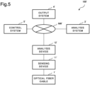
Fig. 5] Fig. 5 is a block diagram illustrating a main portion of an optical fiber sensing system for comparison. - [
Fig. 6] Fig. 6 is a block diagram illustrating a main portion of another portable device according to the first example embodiment. - [
Fig. 7] Fig. 7 is a block diagram illustrating a main portion of another optical fiber sensing system according to the first example embodiment. - [
Fig. 8] Fig. 8 is a block diagram illustrating a main portion of another portable device according to the first example embodiment. - [
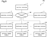
Fig. 9] Fig. 9 is a block diagram illustrating a main portion of an optical fiber sensing system according to a second example embodiment. - Hereinafter, example embodiments of the present invention will be descried in detail with reference to the accompanying drawings.
-
Fig. 1 is a block diagram illustrating a main portion of an optical fiber sensing system according to a first example embodiment.Fig. 2 is a block diagram illustrating a main portion of a portable device and an analysis system according to the first example embodiment. The optical fiber sensing system according to the first example embodiment will be described with reference toFigs. 1 and2 . - As illustrated in
Fig. 1 , an opticalfiber sensing system 100 includes anoptical fiber cable 1, aportable device 2, ananalysis system 3, anoutput system 4, and acontrol system 5. Theportable device 2 can freely communicate with theanalysis system 3 via a network NW. Further, theanalysis system 3 can freely communicate with theoutput system 4 via the network NW. Further, thecontrol system 5 can freely communicate with each of theportable device 2, theanalysis system 3, and theoutput system 4 via the network NW. - As illustrated in
Fig. 2 , theportable device 2 includes asensing unit 11, ananalysis unit 12, and acommunication unit 13. Thecommunication unit 13 is provided in theanalysis unit 12. Further, theportable device 2 includes apower supply circuit 14. Further, theanalysis system 3 includes anAI engine 21. - The
optical fiber cable 1 can be used in optical fiber sensing. Specifically, for example, theoptical fiber cable 1 can be used in detection of vibration, sound, or temperature by distributed optical fiber sensing (distributed fiber optic sensing, DFOS). Hereinafter, data acquired by executing optical fiber sensing using theoptical fiber cable 1 may be collectively referred to as "sensing data". - In the
portable device 2, thesensing unit 11 acquires sensing data by executing optical fiber sensing (more specifically, DFOS) using theoptical fiber cable 1. Thesensing unit 11 is configured by, for example, a distributed vibration sensing (DVS) device or a distributed acoustic sensing (DAS) device. In this case, the sensing data acquired by thesensing unit 11 are a distribution in a longitudinal direction of theoptical fiber cable 1, and include a distribution of vibration intensity or sound intensity for each frequency component. Alternatively, for example, thesensing unit 11 is configured by a distributed temperature sensing (DTS) device. In this case, the sensing data acquired by thesensing unit 11 are a distribution in a longitudinal direction of theoptical fiber cable 1, and include a distribution of a relative value (for example, a ratio of intensity of Raman scattered light) associated with temperature. - In the
portable device 2, theanalysis unit 12 executes predetermined analysis processing (hereinafter, will be referred to as "primary analysis processing") on sensing data acquired by thesensing unit 11. The primary analysis processing includes, for example, processing (so-called "lat-long") of determining a position coordinate associated with the acquired sensing data. Alternatively, for example, the primary analysis processing includes processing of detecting, using the acquired sensing data, occurrence of an abnormality (occurrence of abnormal vibration, occurrence of abnormal sound, occurrence of abnormal temperature change, or the like) around theoptical fiber cable 1. Alternatively, for example, the primary analysis processing includes both the pieces of processing. Various kinds of known techniques can be used in the pieces of processing. Detailed description of the techniques will be omitted. - In the
portable device 2, thecommunication unit 13 of theanalysis unit 12 can freely communicate with theanalysis system 3. Thecommunication unit 13 transmits, to theanalysis system 3, data (hereinafter, may be referred to as "primary analysis data") including a result of primary analysis processing executed by theanalysis unit 12. Theanalysis unit 12 is configured by, for example, a serve device. The server device uses, for example, an on-vehicle computer or a rack mount server. Further, thecommunication unit 13 is configured by, for example, at least one of a wireless communication module and a wired communication module provided in the server device. The wireless communication module uses, for example, a 3rd generation (3G) module, a long term evolution (LTE) module, a 5th generation (5G) module, or a wireless local area network (LAN) module. On the other hand, the wired communication module uses, for example, a wired LAN module. That is, thecommunication unit 13 uses, for example, at least one of a cellular module and a LAN module. - In the
portable device 2, thepower supply circuit 14 supplies electrical power for operation to each of thesensing unit 11 and the analysis unit 12 (including the communication unit 13), by using electrical power supplied from an external power supply PS. That is, thesensing unit 11 executes optical fiber sensing as described above, by using electrical power supplied from thepower supply circuit 14. Further, theanalysis unit 12 executes primary analysis processing as described above, by using electrical power supplied from thepower supply circuit 14. Further, thecommunication unit 13 of theanalysis unit 12 transmits primary analysis data to theanalysis system 3 as described above, by using electrical power supplied from thepower supply circuit 14. The external power supply PS is configured by, for example, an AC power supply for home use or for commercial use. Thepower supply circuit 14 is configured by, for example, a power supply module including an AC-DC converter and a DC-DC converter for transformation (more specifically, for step-down). - The
analysis system 3 receives primary analysis data transmitted from theportable device 2. Theanalysis system 3 executes another predetermined analysis processing (hereinafter, will be referred to as "secondary analysis processing") on the received primary analysis data. That is, the secondary analysis processing is processing based on a result of primary analysis processing in theportable device 2. In other words, the primary analysis processing in theportable device 2 is processing equivalent to preprocessing on the secondary analysis processing in theanalysis system 3. Theanalysis system 3 is configured by, for example, a cloud server. - The secondary analysis processing includes, for example, processing of generating data (hereinafter, will be referred to as "value-added data") having improved value compared with the above received primary analysis data, by processing the primary analysis data. Herein, the "value" is, for example, value for a customer of a service provided by using the optical
fiber sensing system 100. The secondary analysis processing may use thededicated AI engine 21. TheAI engine 21 uses, for example, a learned model generated by machine learning. Theanalysis system 3 inputs the above received primary analysis data to theAI engine 21. TheAI engine 21 outputs value-added data in response to the input, based on a result of machine learning. In this way, value-added data are generated. - The
analysis system 3 transmits the generated value-added data to theoutput system 4. Theoutput system 4 receives the transmitted value-added data. Theoutput system 4 outputs the received value-added data. Thereby, value-added data are provided to the above customer. Alternatively, value-added data are output to another system (not illustrated). Theoutput system 4 is configured by, for example, another cloud server. - Herein, the
output system 4 may output value-added data by displaying, using a graphical user interface (GUI), an image associated with value-added data. Alternatively, theoutput system 4 may output, using an application programming interface (API), value-added data as data of a predetermined format. - As described above, in the
portable device 2, thecommunication unit 13 can freely communicate with theanalysis system 3. In addition thereto, thecommunication unit 13 can freely communicate with thecontrol system 5. Thecontrol system 5 controls an operation of each of thesensing unit 11 and theanalysis unit 12, by communicating with thecommunication unit 13. That is, thesensing unit 11 executes optical fiber sensing as described above, under control of thecontrol system 5. Further, theanalysis unit 12 executes primary analysis processing as described above, under control of thecontrol system 5. Further, thecommunication unit 13 of theanalysis unit 12 transmits primary analysis data to theanalysis system 3 as described above, under control of thecontrol system 5. Thecontrol system 5 is configured by, for example, another cloud server. - Specifically, for example, the
control system 5 transmits, to theportable device 2, a signal (hereinafter, will be referred to as a "first control signal") for controlling an operation of thesensing unit 11 and a signal (hereinafter, will be referred to as a "second control signal") for controlling an operation of theanalysis unit 12. Thecommunication unit 13 receives the transmitted first control signal and the second control signal. Thecommunication unit 13 outputs the received first control signal and the second control signal to theanalysis unit 12. Theanalysis unit 12 executes primary analysis processing, based on the output second control signal, and outputs the output first control signal to thesensing unit 11. Thesensing unit 11 executes optical fiber sensing, based on the output first control signal. - Further, the
control system 5 may control an operation of theanalysis system 3, by communicating with theanalysis system 3. That is, theanalysis system 3 may execute secondary analysis processing as described above, under control of thecontrol system 5. Further, theanalysis system 3 may transmit value-added data to theoutput system 4 as described above, under control of thecontrol system 5. - Further, the
control system 5 may output an operation of theoutput system 4, by communicating with theoutput system 4. That is, theoutput system 4 may output value-added data as described above, under control of thecontrol system 5. - As above, the
control system 5 may control an overall operation of the opticalfiber sensing system 100. - In this way, a main portion of the optical
fiber sensing system 100 is configured. - Hereinafter, the
sensing unit 11 may be referred to as a "sensing means". Theanalysis unit 12 may be referred to as an "analysis means". Thecommunication unit 13 may be referred to as a "communication means". Theanalysis system 3 may be referred to as an "external analysis means". Thecontrol system 5 may be referred to as an "external control means". - Next, a hardware configuration of a main portion of the
portable device 2 will be described with reference toFig. 3 . - As described above, the
sensing unit 11 is configured by, for example, a DVS device, a DAS device, or a DTS device. Theanalysis unit 12 is configured by, for example, a server device. Thecommunication unit 13 is configured by, for example, a communication module provided in a server device. Thepower supply circuit 14 is configured by, for example, a power supply module. - Herein, a DVS device, a DAS device, or a DTS device, a server device (including a communication module), and a power supply module are accommodated in one substantially box-shaped
housing 15. In other words, theportable device 2 includes thehousing 15 accommodating thesensing unit 11, the analysis unit 12 (including the communication unit 13), and thepower supply circuit 14, as illustrated inFig. 3 . Thesensing unit 11, theanalysis unit 12, and thepower supply circuit 14 are fixed, inside thehousing 15, to thehousing 15 by using a not-illustrated screw or the like. Thehousing 15 may include a not-illustrated handle. Thereby, theportable device 2 can be easily carried by a human hand. - In an example illustrated in
Fig. 3 , the communication unit 13 (not illustrated inFig. 3 ) of theanalysis unit 12 uses both of a wireless communication module and a wired communication module. Thus, thecommunication unit 13 can freely communicate with an external system by using a radio wave RW, and can freely communicate with an external system by using a wired communication cable CC1 connected to a wired communication port CP. The radio wave RW is, for example, a radio wave for 3G communication, LTE communication, 5G communication, or wireless LAN communication. The wired communication port CP is, for example, a wired LAN port. The wired communication cable CC1 is, for example, a LAN cable. - Specifically, for example, the
communication unit 13 communicates with theanalysis system 3 by using the radio wave RW, and communicates with thecontrol system 5 by using the wired communication cable CC1 connected to the wired communication port CP. That is, the wired communication port CP may be a wired communication port for control. Further, the wired communication cable CC1 may be a wired communication cable for control. - Further, inside the
housing 15, thesensing unit 11 and theanalysis unit 12 are connected to each other by another wired communication cable CC2. In other words, inside thehousing 15, thesensing unit 11 and theanalysis unit 12 can freely communicate with each other. Thereby, as described above, thesensing unit 11 can output sensing data to theanalysis unit 12. Further, as described above, theanalysis unit 12 can output a first control signal to thesensing unit 11. - Further, as described above, the
power supply circuit 14 supplies electrical power for operation to each of thesensing unit 11 and theanalysis unit 12, by using electrical power supplied from the external power supply PS (not illustrated inFig. 3 ). Thus, thepower supply circuit 14 is electrically connected to the external power supply PS by an AC power supply cable PC1. Further, inside thehousing 15, thesensing unit 11 is electrically connected to thepower supply circuit 14 by a DC power supply cable PC2. Furthermore, inside thehousing 15, theanalysis unit 12 is electrically connected to thepower supply circuit 14 by another DC power supply cable PC3. - Herein, supposing that a power supply circuit for the
sensing unit 11 and a power supply circuit for theanalysis unit 12 are provided separately from each other inside thehousing 15, it is required that two AC power supply cables be connected to theportable device 2. In contrast, the number of AC power supply cables PC1 to be connected to theportable device 2 can be reduced to one, by providing thepower supply circuit 14 shared by thesensing unit 11 and theanalysis unit 12. This can facilitate handling of theportable device 2. - Next, an operation of the
portable device 2, mainly an operation of thesensing unit 11, theanalysis unit 12, and thecommunication unit 13, will be described with reference to a flowchart illustrated inFig. 4 . - First, the
sensing unit 11 executes optical fiber sensing (more specifically, DFOS) using the optical fiber cable 1 (Step ST1). Thereby, sensing data are acquired. Then, theanalysis unit 12 executes primary analysis processing on the sensing data acquired in Step ST1 (Step ST2). A specific example of the primary analysis processing is as described already. Thus, repeated description will be omitted. Then, thecommunication unit 13 of theanalysis unit 12 transmits, to theanalysis system 3, data (that is, primary analysis data) including a result of the primary analysis processing in Step ST2 (Step ST3). - Next, an optical fiber sensing system 100' for comparison with the optical
fiber sensing system 100 will be described with reference toFig. 5 . - As illustrated in
Fig. 5 , the optical fiber sensing system 100' includes an optical fiber cable 1', an analysis system 3', an output system 4', and a control system 5'. The optical fiber cable 1', the analysis system 3', the output system 4', and the control system 5' are similar to theoptical fiber cable 1, theanalysis system 3, theoutput system 4, and thecontrol system 5, in the opticalfiber sensing system 100. - Herein, the optical fiber sensing system 100' includes a sensing device 11' and an analysis device 12', instead of the
portable device 2 in the opticalfiber sensing system 100. The analysis device 12' can freely communicate with the analysis system 3' via a network NW'. - The sensing device 11' includes a function similar to a function included in the
sensing unit 11 of theportable device 2 in the opticalfiber sensing system 100. That is, the sensing device 11' is configured by, for example, a DVS device, a DAS device, or a DTS device. - The analysis device 12' includes a function similar to a function included in the analysis unit 12 (including the communication unit 13) of the
portable device 2 in the opticalfiber sensing system 100. That is, the analysis device 12' is configured by, for example, a server device. The server device is equivalent to an edge computer for a cloud network including the analysis system 3', the output system 4', and the control system 5'. - Next, an effect of using the optical
fiber sensing system 100 will be described. More specifically, an advantageous effect when compared with the optical fiber sensing system 100' will be described. - In the optical fiber sensing system 100', an operation of laying the optical fiber cable 1' and an operation of installing the sensing device 11' are required in order to achieve optical fiber sensing. That is, an operation of bringing the sensing device 11' to a spot where one end of the optical fiber cable 1' is arranged and connecting the one end of the optical fiber cable 1' to the sensing device 11'. In addition thereto, an operation of installing the analysis device 12' is required in order to achieve an analysis (including primary analysis processing and secondary analysis processing) of sensing data. That is, an operation of preparing an edge computer for primary analysis processing and for communication with the analysis system 3' is required.
- In contrast, in the optical
fiber sensing system 100, a function of executing optical fiber sensing, a function of executing primary analysis processing, and a function of transmitting primary analysis data are achieved by theportable device 2. Thus, an operation of preparing an edge computer equivalent to the analysis device 12' is unnecessary, upon achieving an analysis (including primary analysis processing and secondary analysis processing) of sensing data. This can easily achieve an analysis of sensing data, compared with the optical fiber sensing system 100'. - Next, another effect of using the optical
fiber sensing system 100 will be described. More specifically, an advantageous effect when compared with the technique described inPTL 1 will be described. - As described above, the optical fiber distributed temperature measurement device described in
PTL 1 includes an electrical signal control processing block, but does not include a block for communicating with an external system. Thus, there has been a problem of difficulty in achieving an analysis in cooperation with an external system, upon analyzing data acquired by optical fiber sensing. Specifically, for example, there has been a problem of difficulty in analyzing using a dedicated AI engine in an external system. - In contrast, in the optical
fiber sensing system 100, theportable device 2 includes thecommunication unit 13 transmitting primary analysis data to theanalysis system 3. Thereby, an analysis (including primary analysis processing and secondary analysis processing) in cooperation with theanalysis system 3 can be easily achieved. That is, an analysis in cooperation with an external system can be easily achieved, compared with when the optical fiber temperature distribution measurement device described inPTL 1 is used. Specifically, for example, an analysis using thededicated AI engine 21 in an external system (the analysis system 3) can be easily achieved. - Next, a modified example of the
portable device 2 will be described. - In the
portable device 2, each of thesensing unit 11 and theanalysis unit 12 may be unitized, and individual units may be configured detachably to thehousing 15. Further, there may be provided a structure in which, when individual units are accommodated in thehousing 15, the accommodated units are electrically connected to thepower supply circuit 14. - Thereby, in the
portable device 2, a selectedsensing unit 11 among a plurality of types ofsensing units 11 prepared in advance may be mounted. The plurality of types ofsensing units 11 may execute, for example, sensing (for example, DVS, DAS, or DTS) different from each other. - Further, in the
portable device 2, a selectedanalysis unit 12 among a plurality of types ofanalysis units 12 prepared in advance may be mounted. The plurality of types ofanalysis units 12 may execute, for example, primary analysis processing of different contents from each other. - Next, another modified example of the
portable device 2 will be described with reference toFig. 6 . - As illustrated in
Fig. 6 , theportable device 2 may include abattery 16 instead of thepower supply circuit 14. Thebattery 16 supplies electrical power for operation to each of thesensing unit 11 and the analysis unit 12 (including the communication unit 13). Thebattery 16 is accommodated in thehousing 15. Use of thebattery 16 can reduce the number of AC power supply cables to be connected to theportable device 2 to zero. This can further facilitate handling of theportable device 2. - Next, a modified example of the optical
fiber sensing system 100 will be described with reference toFig. 7 . Further, another modified example of theportable device 2 will be described with reference toFig. 8 . - As illustrated in
Fig. 7 , the opticalfiber sensing system 100 may include theportable device 2 and theanalysis system 3. In other words, a main portion of the opticalfiber sensing system 100 may be configured by theportable device 2 and theanalysis system 3. In this case, theoutput system 4 and thecontrol system 5 may be provided outside the opticalfiber sensing system 100. Herein, as illustrated inFig. 8 , theportable device 2 may include thesensing unit 11, theanalysis unit 12, thecommunication unit 13, and thehousing 15. In other words, a main portion of theportable device 2 may be configured by thesensing unit 11, theanalysis unit 12, thecommunication unit 13, and thehousing 15. In this case, thepower supply circuit 14 or thebattery 16 may be provided outside theportable device 2. - Even in this case, an effect as described above can be exhibited. That is, the
sensing unit 11 of theportable device 2 executes optical fiber sensing using the optical fiber cable 1 (not illustrated inFigs. 7 and8 ). Theanalysis unit 12 of theportable device 2 executes primary analysis processing on sensing data acquired by the optical fiber sensing. Thecommunication unit 13 of theportable device 2 transmits, to theanalysis system 3 executing secondary analysis processing based on a result of the primary analysis processing outside theportable device 2, data (primary analysis data) including a result of the primary analysis processing. By theportable device 2 transmitting the primary analysis data to theanalysis system 3, an analysis in cooperation with theanalysis system 3 can be easily achieved. That is, an analysis in cooperation with an external system can be easily achieved. Further, an operation of preparing an edge computer equivalent to the analysis device 12' can be eliminated. -
Fig. 9 is a block diagram illustrating a main portion of an optical fiber sensing system according to a second example embodiment. The optical fiber sensing system according to the second example embodiment will be described with reference toFig. 9 . Note that, inFig. 9 , a block similar to a block illustrated inFig. 1 is assigned with an identical reference sign, and description therefor will be omitted. - As illustrated in
Fig. 9 , an opticalfiber sensing system 100a includes N optical fiber cables 1_1 to 1_N and M portable devices 2_1 to 2_M. Herein, each of N and M is an integer equal to or more than 2. In an example illustrated inFig. 9 , N=M holds, and the portable devices 2_1 to 2_M are associated one by one with the optical fiber cables 1_1 to 1_N. Each of the portable devices 2_1 to 2_M can freely communicate with ananalysis system 3 via a network NW. Further, acontrol system 5 can freely communicate with each of the portable devices 2_1 to 2_M, theanalysis system 3, and anoutput system 4 via the network NW. - The individual
optical fiber cable 1 in the opticalfiber sensing system 100a is similar to theoptical fiber cable 1 in the opticalfiber sensing system 100 according to the first example embodiment. Further, the individualportable device 2 in the opticalfiber sensing system 100a is similar to theportable device 2 in the opticalfiber sensing system 100 according to the first example embodiment. - That is, a sensing unit 11 (not illustrated in
Fig. 9 ) of the individualportable device 2 acquires sensing data by executing optical fiber sensing (more specifically, DFOS) using the associatedoptical fiber cable 1. An analysis unit 12 (not illustrated inFig. 9 ) of the individualportable device 2 executes primary analysis processing on the acquired sensing data. A communication unit 13 (not illustrated inFig. 9 ) of the individualportable device 2 transmits primary analysis data to theanalysis system 3. - The
analysis system 3 receives primary analysis data transmitted from the individualportable device 2. Thereby, primary analysis data indicating a result of primary analysis processing in the M portable devices 2_1 to 2_M are received. Theanalysis system 3 executes secondary analysis processing on the received primary analysis data. That is, the secondary analysis processing is processing based on a result of the primary analysis processing in the M portable devices 2_1 to 2_M. In other words, the primary analysis processing in the individualportable device 2 is processing equivalent to preprocessing on the secondary analysis processing in theanalysis system 3. The secondary analysis processing may use a dedicated AI engine 21 (not illustrated inFig. 9 ), as described in the first example embodiment. - The
control system 5 controls an operation of each of thesensing unit 11 and theanalysis unit 12 in the individualportable device 2, by communicating with thecommunication unit 13 of the individualportable device 2. - In this way, a main portion of the optical
fiber sensing system 100a is configured. - Next, an effect of using the optical
fiber sensing system 100a will be described. More specifically, an advantageous effect when compared with the technique described inPTL 1 will be described. - As described above, the optical fiber distributed temperature measurement device described in
PTL 1 includes an electrical signal control processing block, but does not include a block for communicating with an external system. Thus, there has been a problem of difficulty in achieving an analysis in cooperation with an external system, upon analyzing data acquired by optical fiber sensing. Specifically, for example, there has been a problem of difficulty in analyzing using a dedicated AI engine in an external system, or in complexly analyzing data acquired by a plurality of optical fiber distributed temperature measurement devices. - In contrast, in the optical
fiber sensing system 100a, the individualportable device 2 includes thecommunication unit 13 transmitting primary analysis data to theanalysis system 3. Thereby, an analysis (including primary analysis processing and secondary analysis processing) in cooperation with theanalysis system 3 can be easily achieved. That is, an analysis in cooperation with an external system can be easily achieved, compared with when the optical fiber temperature distribution measurement device described inPTL 1 is used. Specifically, for example, an analysis using thededicated AI engine 21 in an external system (the analysis system 3) can be easily achieved. Further, for example, a complex analysis of primary analysis data acquired by the M portable devices 2_1 to 2_M can be facilitated. - Next, a modified example of the individual
portable device 2 will be described. - The individual
portable device 2 can employ various modified examples similar to those described in the first example embodiment. For example, the individualportable device 2 may include abattery 16 instead of apower supply circuit 14, as illustrated inFig. 6 . Further, for example, a main portion of the individualportable device 2 may be configured by thesensing unit 11, theanalysis unit 12, thecommunication unit 13, and ahousing 15, as illustrated inFig. 8 . - Next, a modified example of the optical
fiber sensing system 100a will be described. - The number M of the portable devices 2_1 to 2_M may be different from the number N of the optical fiber cables 1_1 to 1_N (N≠M). In this case, the individual
portable device 2 may execute optical fiber sensing using equal to or more than twooptical fiber cables 1. - Besides the above, the optical
fiber sensing system 100a can employ various modified examples similar to those described in the first example embodiment. For example, a main portion of the opticalfiber sensing system 100a may be configured by the portable devices 2_1 to 2_M and theanalysis system 3, similarly to an example described with reference toFig. 7 . - While the invention has been particularly shown and described with reference to exemplary embodiments thereof, the invention is not limited to these embodiments. It will be understood by those of ordinary skill in the art that various changes in form and details may be made therein without departing from the spirit and scope of the present invention as defined by the claims.
- The whole or part of the example embodiments described above can be described as, but not limited to, the following supplementary notes.
- A portable device including:
- a sensing means for executing optical fiber sensing using an optical fiber cable;
- an analysis means for executing primary analysis processing on sensing data acquired by the optical fiber sensing;
- a communication means for transmitting, to an external analysis means for executing secondary analysis processing based on a result of the primary analysis processing outside the portable device, data including a result of the primary analysis processing; and
- a housing accommodating the sensing means, the analysis means, and the communication means.
- The portable device according to
supplementary note 1, wherein - the communication means is provided in the analysis means,
- the portable device further includes a power supply circuit supplying electrical power for operation to the sensing means and the analysis means, by using electrical power supplied from an external power supply via a power supply cable, and
- the housing accommodates the power supply circuit.
- The portable device according to
supplementary note 1, wherein - the communication means is provided in the analysis means,
- the portable device further includes a battery supplying electrical power for operation to the sensing means and the analysis means, and
- the housing accommodates the battery.
- The portable device according to any one of
supplementary notes 1 to 3, wherein - the communication means communicates with the external analysis means and communicates with an external control means for controlling an operation of the sensing means and the analysis means outside the portable device, and
- the external control means controls an operation of the sensing means and the analysis means, by communicating with the communication means.
- The portable device according to any one of
supplementary notes 1 to 4, wherein the primary analysis processing includes at least one of processing of determining a position coordinate associated with the sensing data and processing of detecting occurrence of an abnormality around the optical fiber cable. - The portable device according to any one of
supplementary notes 1 to 5, wherein - the external analysis means includes an AI engine for use in the secondary analysis processing, and
- the external analysis means executes the secondary analysis processing by using the AI engine.
- The portable device according to any one of
supplementary notes 1 to 6, wherein the analysis means uses an on-vehicle computer or a rack mount server. - The portable device according to any one of
supplementary notes 1 to 7, wherein the communication means uses at least one of a cellular module and a LAN module. - An optical fiber sensing system including:
- the portable device according to any one of
supplementary notes 1 to 8; and - the external analysis means.
- An analysis method including, by a portable device:
- executing optical fiber sensing using an optical fiber cable;
- executing primary analysis processing on sensing data acquired by the optical fiber sensing; and
- transmitting, to an external analysis means for executing secondary analysis processing based on a result of the primary analysis processing outside the portable device, data including a result of the primary analysis processing.
-
- 1
- Optical fiber cable
- 2
- Portable device
- 3
- Analysis system (external analysis means)
- 4
- Output system
- 5
- Control system (external control means)
- 11
- Sensing unit (sensing means)
- 12
- Analysis unit (analysis means)
- 13
- Communication unit (communication means)
- 14
- Power supply circuit
- 15
- Housing
- 16
- Battery
- 21
- AI engine
- 100, 100a
- Optical fiber sensing system
Claims (10)
- A portable device comprising:sensing means for executing optical fiber sensing using an optical fiber cable;analysis means for executing primary analysis processing on sensing data acquired by the optical fiber sensing;communication means for transmitting, to external analysis means for executing secondary analysis processing based on a result of the primary analysis processing outside the portable device, data including a result of the primary analysis processing; anda housing accommodating the sensing means, the analysis means, and the communication means.
- The portable device according to claim 1, whereinthe communication means is provided in the analysis means,the portable device further comprises a power supply circuit supplying electrical power for operation to the sensing means and the analysis means, by using electrical power supplied from an external power supply via a power supply cable, andthe housing accommodates the power supply circuit.
- The portable device according to claim 1, whereinthe communication means is provided in the analysis means,the portable device further comprises a battery supplying electrical power for operation to the sensing means and the analysis means, andthe housing accommodates the battery.
- The portable device according to any one of claims 1 to 3, whereinthe communication means communicates with the external analysis means and communicates with external control means for controlling an operation of the sensing means and the analysis means outside the portable device, andthe external control means controls an operation of the sensing means and the analysis means, by communicating with the communication means.
- The portable device according to any one of claims 1 to 4, wherein the primary analysis processing includes at least one of processing of determining a position coordinate associated with the sensing data and processing of detecting occurrence of an abnormality around the optical fiber cable.
- The portable device according to any one of claims 1 to 5, whereinthe external analysis means includes an AI engine for use in the secondary analysis processing, andthe external analysis means executes the secondary analysis processing by using the AI engine.
- The portable device according to any one of claims 1 to 6, wherein the analysis means uses an on-vehicle computer or a rack mount server.
- The portable device according to any one of claims 1 to 7, wherein the communication means uses at least one of a cellular module and a LAN module.
- An optical fiber sensing system comprising:the portable device according to any one of claims 1 to 8; andthe external analysis means.
- An analysis method comprising, by a portable device:executing optical fiber sensing using an optical fiber cable;executing primary analysis processing on sensing data acquired by the optical fiber sensing; andtransmitting, to external analysis means for executing secondary analysis processing based on a result of the primary analysis processing outside the portable device, data including a result of the primary analysis processing.
Applications Claiming Priority (1)
| Application Number | Priority Date | Filing Date | Title |
|---|---|---|---|
| PCT/JP2021/013047 WO2022201532A1 (en) | 2021-03-26 | 2021-03-26 | Portable device, optical fiber sensing system, and analysis method |
Publications (2)
| Publication Number | Publication Date |
|---|---|
| EP4276419A1 true EP4276419A1 (en) | 2023-11-15 |
| EP4276419A4 EP4276419A4 (en) | 2024-02-28 |
Family
ID=83396508
Family Applications (1)
| Application Number | Title | Priority Date | Filing Date |
|---|---|---|---|
| EP21933135.2A Withdrawn EP4276419A4 (en) | 2021-03-26 | 2021-03-26 | Portable device, optical fiber sensing system, and analysis method |
Country Status (4)
| Country | Link |
|---|---|
| US (1) | US20240125627A1 (en) |
| EP (1) | EP4276419A4 (en) |
| JP (1) | JPWO2022201532A1 (en) |
| WO (1) | WO2022201532A1 (en) |
Family Cites Families (8)
| Publication number | Priority date | Publication date | Assignee | Title |
|---|---|---|---|---|
| US7542856B2 (en) * | 2003-07-02 | 2009-06-02 | Neubrex Co., Ltd. | Structure monitor system |
| JP2005057792A (en) * | 2004-09-09 | 2005-03-03 | Nippon Telegr & Teleph Corp <Ntt> | Optical communication network damage status assessment method |
| US20140222370A1 (en) * | 2011-09-02 | 2014-08-07 | Robert Manzke | Rapid dense point cloud imaging using probabilistic voxel maps |
| JP5867689B2 (en) | 2011-10-04 | 2016-02-24 | 横河電機株式会社 | Electronic device storage case connection structure |
| KR20190049729A (en) * | 2016-09-15 | 2019-05-09 | 아벤트, 인크. | System and method for in situ visualization of neurons using targeted fluorescent molecules |
| US20220151556A1 (en) * | 2019-02-26 | 2022-05-19 | Nec Corporation | Optical fiber sensing system, state detection device, state detection method, and non-transitory computer-readable medium |
| CN113631896A (en) * | 2019-03-29 | 2021-11-09 | 日本电气株式会社 | Monitoring system, monitoring device, monitoring method and non-transitory computer readable medium |
| DE102019108278A1 (en) * | 2019-03-29 | 2020-10-01 | Liebherr-Components Biberach Gmbh | Device for determining the current state and / or the remaining service life of a construction machine |
-
2021
- 2021-03-26 JP JP2023508402A patent/JPWO2022201532A1/ja active Pending
- 2021-03-26 WO PCT/JP2021/013047 patent/WO2022201532A1/en not_active Ceased
- 2021-03-26 US US18/276,783 patent/US20240125627A1/en active Pending
- 2021-03-26 EP EP21933135.2A patent/EP4276419A4/en not_active Withdrawn
Also Published As
| Publication number | Publication date |
|---|---|
| JPWO2022201532A1 (en) | 2022-09-29 |
| US20240125627A1 (en) | 2024-04-18 |
| EP4276419A4 (en) | 2024-02-28 |
| WO2022201532A1 (en) | 2022-09-29 |
Similar Documents
| Publication | Publication Date | Title |
|---|---|---|
| US11567537B2 (en) | Systems, methods and devices for native and virtualized video in a hybrid docking station | |
| US8976039B2 (en) | Remote operation and monitoring of measurement systems and remote measurement data processing | |
| EP3382502A1 (en) | Power supplying apparatus, power supplying control apparatus, and power supplying control method | |
| WO2012121544A2 (en) | Wireless network system, wireless device, and network registration method of the wireless device | |
| US11750407B2 (en) | Bidirectional power feed digital communication device | |
| WO2018038423A1 (en) | Power supply apparatus, electronic device receiving power, and control method therefor | |
| US20240129144A1 (en) | Bidirectional power feed digital communication device | |
| CN104037885A (en) | Portable power source, working condition monitoring system of portable power source and monitoring management method of portable power source | |
| WO2019192756A1 (en) | Configurable and modular light fixtures | |
| CN105577717B (en) | Control method and system compatible with connection of multiple different electrical appliances | |
| WO2024019474A1 (en) | Bi-directional inverter with solar inverter function | |
| CN109143019A (en) | A kind of protective relaying device board Auto-Test System | |
| EP4276419A1 (en) | Portable device, optical fiber sensing system, and analysis method | |
| WO2022005105A1 (en) | Provisioning device and method, for diagnosing state of battery and assigning id | |
| CN109787829A (en) | For generating the method and device of information | |
| US11281611B2 (en) | General purpose interface bus (GPIB) sniffer system and method | |
| US20200241073A1 (en) | Host illumination of indicators of an ac adapter | |
| CN216673018U (en) | General type transmitter testing arrangement | |
| CN110633766A (en) | Two-dimensional code generation device for reporting result of environment monitoring instrument | |
| CN109936477A (en) | Method and apparatus for sending information | |
| CN210155335U (en) | Testing device for multimode navigation receiver | |
| CN112394276B (en) | Wireless charging test method, device, system, electronic equipment and storage medium | |
| CN115134852A (en) | Real network SIM card auxiliary test system and test method based on same | |
| US20260100731A1 (en) | Shared reverse power feed digital communication devices | |
| CN223217557U (en) | A multi-channel signal source integrated generator and test device |
Legal Events
| Date | Code | Title | Description |
|---|---|---|---|
| STAA | Information on the status of an ep patent application or granted ep patent |
Free format text: STATUS: THE INTERNATIONAL PUBLICATION HAS BEEN MADE |
|
| PUAI | Public reference made under article 153(3) epc to a published international application that has entered the european phase |
Free format text: ORIGINAL CODE: 0009012 |
|
| STAA | Information on the status of an ep patent application or granted ep patent |
Free format text: STATUS: REQUEST FOR EXAMINATION WAS MADE |
|
| 17P | Request for examination filed |
Effective date: 20230810 |
|
| AK | Designated contracting states |
Kind code of ref document: A1 Designated state(s): AL AT BE BG CH CY CZ DE DK EE ES FI FR GB GR HR HU IE IS IT LI LT LU LV MC MK MT NL NO PL PT RO RS SE SI SK SM TR |
|
| A4 | Supplementary search report drawn up and despatched |
Effective date: 20240125 |
|
| RIC1 | Information provided on ipc code assigned before grant |
Ipc: G01D 5/353 20060101AFI20240119BHEP |
|
| STAA | Information on the status of an ep patent application or granted ep patent |
Free format text: STATUS: THE APPLICATION HAS BEEN WITHDRAWN |
|
| 18W | Application withdrawn |
Effective date: 20240507 |