EP4276403A1 - Clearance sensor - Google Patents
Clearance sensor Download PDFInfo
- Publication number
- EP4276403A1 EP4276403A1 EP22766846.4A EP22766846A EP4276403A1 EP 4276403 A1 EP4276403 A1 EP 4276403A1 EP 22766846 A EP22766846 A EP 22766846A EP 4276403 A1 EP4276403 A1 EP 4276403A1
- Authority
- EP
- European Patent Office
- Prior art keywords
- electrode
- guard
- central axis
- ground
- detection
- Prior art date
- Legal status (The legal status is an assumption and is not a legal conclusion. Google has not performed a legal analysis and makes no representation as to the accuracy of the status listed.)
- Granted
Links
Images




Classifications
-
- G—PHYSICS
- G01—MEASURING; TESTING
- G01B—MEASURING LENGTH, THICKNESS OR SIMILAR LINEAR DIMENSIONS; MEASURING ANGLES; MEASURING AREAS; MEASURING IRREGULARITIES OF SURFACES OR CONTOURS
- G01B7/00—Measuring arrangements characterised by the use of electric or magnetic techniques
- G01B7/14—Measuring arrangements characterised by the use of electric or magnetic techniques for measuring distance or clearance between spaced objects or spaced apertures
Definitions
- the present disclosure relates to a clearance sensor.
- a rotary machine such as an axial compressor including a plurality of rotor blades rotating inside a casing formed in a cylindrical shape is known.
- a tip clearance sensor that measures a tip clearance between the casing and the rotor blade is provided, and the value of the measured tip clearance is maintained to be appropriate.
- a tip clearance sensor for example, a non-contact type sensor such as a capacitance type sensor is used (see, for example, PTL 1).
- the clearance sensor described in PTL 1 has a three-layer structure including a detection electrode, a guard electrode, and a ground electrode of which the central axes are coaxial with each other and insulation layers are disposed between the electrodes.
- the insulation layers are attached by means of thermal spraying or the like, and assembly of each electrode is performed along with fit adjustment.
- a variation in assembly accuracy becomes great and there may be a decrease in reliability, for example, in a case where the tip clearance is to be measured for a long period of time as described above.
- the present disclosure has been made in view of such circumstances and an object thereof is to provide a clearance sensor with which it is possible to suppress a decrease in long-term measurement reliability.
- a clearance sensor including an electrode member that includes a columnar detection electrode including a detection end surface on one end side in an axial direction along a central axis and that includes a guard electrode and a ground electrode of which central axes are coaxial with the central axis of the detection electrode, an insulation member that connects the detection electrode and the guard electrode to each other and that connects the guard electrode and the ground electrode to each other, and an insulation layer that fills a gap between the detection electrode, the guard electrode, the ground electrode, and the insulation member.
- the electrode member and the insulation member are locked to each other in at least one of the axial direction along the central axis and a direction around the central axis.
- a clearance sensor including an electrode member that includes a columnar detection electrode including a detection end surface on one end side in an axial direction along a central axis and that includes a guard electrode and a ground electrode of which central axes are coaxial with the central axis of the detection electrode, an insulation member that connects the detection electrode and the guard electrode to each other and that connects the guard electrode and the ground electrode to each other, an insulation layer that fills a gap between the detection electrode, the guard electrode, the ground electrode, and the insulation member, and a cooling flow path that penetrates the electrode member and the insulation member in the axial direction along the central axis.
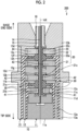
- Fig. 1 is a view showing an example of a clearance sensor 100 according to the present embodiment.
- Fig. 1 shows an example of a cross-sectional configuration cut along a plane passing through a central axis AX.
- the clearance sensor 100 shown in Fig. 1 is a capacitance sensor.
- the clearance sensor 100 can be used, for example, in the case of measurement or the like of a tip clearance between a casing and a plurality of rotor blades of an axial compressor that includes the rotor blades rotating inside the casing formed in a cylindrical shape as in the case of a gas turbine or the like.
- the clearance sensor 100 includes electrode members 10, insulation members 20, and insulation layers 30.
- the electrode members 10 include a detection electrode 11, a guard electrode 12, and a ground electrode 13.
- the electrode members 10 are formed of, for example, metal or alloy such as stainless steel.
- the central axes AX of the detection electrode 11, the guard electrode 12, and the ground electrode 13 are coaxial with each other and the detection electrode 11, the guard electrode 12, and the ground electrode 13 are provided to form three layers arranged in a radial direction.
- the detection electrode 11 is a columnar electrode centered on the central axis AX.
- the detection electrode 11 includes a detection end surface 11a at one end in an axial direction along the central axis AX.
- the detection end surface 11a side in the axial direction along the central axis AX may be referred to as a tip side and a side opposite to the detection end surface 11a side may be referred to as a base end side in a case where the positional relationship of the clearance sensor 100 is to be described.
- the clearance sensor 100 measures a tip clearance in a state where the detection end surface 11a is disposed at a corresponding position on an inner peripheral surface of a casing.
- the detection electrode 11 is connected to, for example, an inorganic insulation (MI) cable.
- the MI cable includes a wire portion 14, a tubular member 15, and a tubular component 16.
- the wire portion 14, the tubular member 15, and the tubular component 16 of the MI cable form a three-layer structure, and insulators such as magnesium oxide fill gaps between the components.
- the wire portion 14 is bonded to the detection electrode 11 through welding or the like.
- the wire portion 14 is disposed to extend from the detection electrode 11 to the other end side in the axial direction along the central axis AX.
- the wire portion 14 is connected to a processing device (not shown) or the like.
- the wire portion 14 can be disposed on, for example, the central axis AX.
- the tubular member 15 is bonded to a guard base portion 12b, which will be described later, through welding or the like.
- the tubular component 16 is bonded to a ground base portion 13b, which will be described later, through welding or the like.
- the detection electrode 11 includes a recess portion 11d at an end surface 11b on the base end side.
- the recess portion 11d has a shape obtained by hollowing out the end surface 11b in a columnar shape extending toward the tip side.
- the inner peripheral surface of the recess portion 11d is a cylindrical surface.
- a screw thread 11e is formed on the inner peripheral surface of the recess portion 11d. The screw thread 11e is spirally formed on the inner peripheral surface of the recess portion 11d from the base end side to the tip side.
- the guard electrode 12 includes a guard cylindrical portion 12a that is centered on the central axis AX and that has a cylindrical shape and the guard base portion 12b that is centered on the central axis AX and that has a columnar shape.
- the central axis of the guard electrode 12 is coaxial with the central axis of the detection electrode 11.
- the guard cylindrical portion 12a surrounds an outer peripheral surface 11c of the detection electrode 11.
- the guard cylindrical portion 12a is disposed with a predetermined gap provided between the guard cylindrical portion 12a and the outer peripheral surface 11c of the detection electrode 11.
- a tip side end surface of the guard cylindrical portion 12a is flush with the detection end surface 11a of the detection electrode 11.
- the guard base portion 12b is disposed on the other end side in the axial direction along the central axis AX with respect to the detection electrode 11.
- the guard base portion 12b is connected to the guard cylindrical portion 12a through, for example, welding or the like.
- the guard base portion 12b includes a recess portion 12d at an end surface 12c on the tip side.
- the recess portion 12d has a shape obtained by hollowing out the end surface 12c in a columnar shape extending toward the base end side.
- the inner peripheral surface of the recess portion 12d is a cylindrical surface.
- a screw thread 12e is formed on the inner peripheral surface of the recess portion 12d. The screw thread 12e is spirally formed on the inner peripheral surface of the recess portion 12d from the tip side to the base end side.
- the guard base portion 12b includes a recess portion 12g at an end surface 12f on the base end side.
- the recess portion 12g has a shape obtained by hollowing out the end surface 12f in a columnar shape extending toward the base end side.
- the inner peripheral surface of the recess portion 12g is a cylindrical surface.
- a screw thread 12h is formed on the inner peripheral surface of the recess portion 12g.
- the screw thread 12h is spirally formed on the inner peripheral surface of the recess portion 12g from the tip side to the base end side.
- the ground electrode 13 includes a ground cylindrical portion 13a that is centered on the central axis AX and that has a cylindrical shape and the ground base portion 13b that is centered on the central axis AX and that has a columnar shape.
- the central axis of the ground electrode 13 is coaxial with the central axes of the detection electrode 11 and the guard electrode 12.
- the ground cylindrical portion 13a surrounds an outer peripheral surface of the guard electrode 12.
- the ground cylindrical portion 13a is disposed with a predetermined gap provided between the ground cylindrical portion 13a and the outer peripheral surface of the guard electrode 12.
- a tip side end surface of the ground cylindrical portion 13a is flush with the detection end surface 11a of the detection electrode 11 and a tip side end surface of the guard cylindrical portion 12a.
- the ground base portion 13b is disposed on the other end side in the axial direction along the central axis AX with respect to the guard electrode 12.
- the ground base portion 13b is connected to the ground cylindrical portion 13a through, for example, welding or the like.
- the ground base portion 13b includes a recess portion 13d at an end surface 13c on the tip side.
- the recess portion 13d has a shape obtained by hollowing out the end surface 13c in a columnar shape extending toward the base end side.
- the inner peripheral surface of the recess portion 13d is a cylindrical surface.
- a screw thread 13e is formed on the inner peripheral surface of the recess portion 13d. The screw thread 13e is spirally formed on the inner peripheral surface of the recess portion 13d from the tip side to the base end side.
- the insulation members 20 connect the detection electrode 11 and the guard electrode 12 to each other and connect the guard electrode 12 and the ground electrode 13 to each other.
- the insulation members 20 include a first insulation member 21 and a second insulation member 22.
- the first insulation member 21 and the second insulation member 22 are formed of insulators such as ceramics.
- the first insulation member 21 is disposed between the detection electrode 11 and the guard base portion 12b in the axial direction along the central axis AX.
- the first insulation member 21 connects the detection electrode 11 and the guard base portion 12b to each other in the axial direction.
- the first insulation member 21 has a base portion 21a and protrusion portions 21b and 21c.
- the base portion 21a has a columnar shape centered on the central axis AX.
- the protrusion portion 21b protrudes from the base portion 21a toward the tip side.
- the protrusion portion 21c protrudes from the base portion 21a to the base end side.
- Each of the protrusion portions 21b and 21c has a columnar shape centered on the central axis AX and has a diameter smaller than that of the base portion 21a, for example.
- the diameter of the protrusion portion 21b is set such that the protrusion portion 21b can be inserted into the recess portion 11d of the detection electrode 11 described above.
- An outer peripheral surface of the protrusion portion 21b is a cylindrical surface.
- a screw thread 21d is formed on the outer peripheral surface of the protrusion portion 21b.
- the screw thread 21d is spirally formed on the outer peripheral surface of the protrusion portion 21b from the base end side to the tip side such that the screw thread 21d is screw-bonded to the screw thread 11e of the recess portion 11d of the detection electrode 11 described above.
- the protrusion portion 21b is inserted into the recess portion 11d of the detection electrode 11 in a state where the screw thread 21d and the screw thread 11e are screw-bonded to each other. In this manner, the first insulation member 21 is screw-bonded to the detection electrode 11.
- the diameter of the protrusion portion 21c is set such that the protrusion portion 21c can be inserted into the recess portion 12d of the guard electrode 12 described above.
- An outer peripheral surface of the protrusion portion 21c is a cylindrical surface.
- a screw thread 21e is formed on the outer peripheral surface of the protrusion portion 21c.
- the screw thread 21e is spirally formed on the outer peripheral surface of the protrusion portion 21c from the base end side to the tip side such that the screw thread 21e is screw-bonded to the screw thread 12e of the recess portion 12d of the guard electrode 12 described above.
- the protrusion portion 21c is inserted into the recess portion 12d of the guard electrode 12 in a state where the screw thread 21e and the screw thread 12e are screw-bonded to each other. In this manner, the first insulation member 21 is screw-bonded to the guard electrode 12.
- the second insulation member 22 is disposed between the guard base portion 12b and the ground base portion 13b in the axial direction along the central axis AX.
- the second insulation member 22 connects the guard base portion 12b and the ground base portion 13b to each other in the axial direction.
- the second insulation member 22 has a base portion 22a and protrusion portions 22b and 22c.
- the base portion 22a has a columnar shape centered on the central axis AX.
- the protrusion portion 22b protrudes from the base portion 22a toward the tip side.
- the protrusion portion 22c protrudes from the base portion 22a to the base end side.
- Each of the protrusion portions 22b and 22c has a columnar shape centered on the central axis AX and has a diameter smaller than that of the base portion 22a, for example.
- the diameter of the protrusion portion 22b is set such that the protrusion portion 22b can be inserted into the recess portion 12g of the guard electrode 12 described above.
- An outer peripheral surface of the protrusion portion 22b is a cylindrical surface.
- a screw thread 22d is formed on the outer peripheral surface of the protrusion portion 22b.
- the screw thread 22d is spirally formed on the outer peripheral surface of the protrusion portion 22b from the base end side to the tip side such that the screw thread 22d is screw-bonded to the screw thread 12h of the recess portion 12g of the guard electrode 12 described above.
- the protrusion portion 22b is inserted into the recess portion 12g of the guard electrode 12 in a state where the screw thread 22d and the screw thread 12h are screw-bonded to each other. In this manner, the second insulation member 22 is screw-bonded to the guard electrode 12.
- the diameter of the protrusion portion 22c is set such that the protrusion portion 22c can be inserted into the recess portion 13d of the ground electrode 13 described above.
- An outer peripheral surface of the protrusion portion 22c is a cylindrical surface.
- a screw thread 22e is formed on the outer peripheral surface of the protrusion portion 22c.
- the screw thread 22e is spirally formed on the outer peripheral surface of the protrusion portion 22c from the base end side to the tip side such that the screw thread 22e is screw-bonded to the screw thread 13e of the recess portion 13d of the ground electrode 13 described above.
- the protrusion portion 22c is inserted into the recess portion 13d of the ground electrode 13 in a state where the screw thread 22e and the screw thread 13e are screw-bonded to each other. In this way, the second insulation member 22 is screw-bonded to the ground electrode 13.
- the electrode members 10 and the insulation members 20 are locked to each other in at least one of the axial direction along the central axis AX and a direction around the central axis AX with the recess portion 11d of the detection electrode 11 being screw-bonded to the protrusion portion 21b of the first insulation member 21, the protrusion portion 21c of the first insulation member 21 being screw-bonded to the recess portion 12d of the guard electrode 12, the recess portion 12g of the guard electrode 12 being screw-bonded to the protrusion portion 22b of the second insulation member 22, and the protrusion portion 22c of the second insulation member 22 being screw-bonded to the recess portion 13d of the ground electrode 13.
- the insulation layers 30 for example, a ceramic-based insulating adhesive agent or the like is used.
- the insulation layers 30 fill gaps between the detection electrode 11, the guard electrode 12, the ground electrode 13, and the insulation members 20 (the first insulation member 21 and the second insulation member 22). Since the insulation layers 30 are disposed, it is possible to insulate the detection electrode 11, the guard electrode 12, and the ground electrode 13 from each other and to suppress relative rotational movement in the direction around the central axis AX.
- the insulation layers 30 are disposed to fill a gap between screw parts or the like between the first insulation member 21 and the detection electrode 11, between the first insulation member 21 and the guard electrode 12, between the second insulation member 22 and the guard electrode 12, and between the second insulation member 22 and the ground electrode 13. Accordingly, relative rotational movement of each component can be suppressed.
- the clearance sensor 100 includes the electrode members 10 that include the columnar detection electrode 11 including the detection end surface on one end side in the axial direction along the central axis AX and that include the guard electrode 12 and the ground electrode 13 of which the central axes AX are coaxial with the central axis AX of the detection electrode 11, the insulation members 20 that connect the detection electrode 11 and the guard electrode 12 to each other and that connect the guard electrode 12 and the ground electrode 13 to each other, and the insulation layers 30 that fill gaps between the detection electrode 11, the guard electrode 12, the ground electrode 13, and the insulation members 20.
- the electrode members 10 and the insulation members 20 are locked to each other in at least one of the axial direction along the central axis AX and the direction around the central axis AX.
- the electrode members 10 and the insulation members 20 are locked to each other so that positional deviation between the electrode members 10 and the insulation members 20 can be suppressed. Therefore, it is possible to suppress a decrease in long-term measurement reliability.
- wear of the insulation members 20 and delamination of the insulation layers 30 caused by a thermal elongation difference and vibrations can be suppressed and thus reliability can be maintained for a long period of time.
- the guard electrode 12 includes the guard cylindrical portion 12a that surrounds the outer peripheral surface of the detection electrode 11 and the guard base portion 12b that is disposed on the base end side in the axial direction with respect to the detection electrode 11 and that is connected to the guard cylindrical portion 12a
- the ground electrode 13 includes the ground cylindrical portion 13a that surrounds the outer peripheral surface of the guard electrode 12 and the ground base portion 13b that is disposed on the base end side with respect to the guard electrode 12 and that is connected to the ground cylindrical portion 13a
- the insulation members 20 include the first insulation member 21 that connects the detection electrode 11 and the guard base portion 12b to each other in the axial direction and the second insulation member 22 that connects the guard base portion 12b and the ground base portion 13b to each other in the axial direction. Therefore, since the base portions of the respective electrodes constituting the electrode members 10 are connected to each other by the insulation members 20 and connection portions are locked, positional deviation between the electrode members 10 and the insulation members 20 can be more reliably suppressed.
- the electrode members 10 and the insulation members 20 are locked to each other by being screw-bonded to each other. Therefore, the positional deviation between the electrode members 10 and the insulation members 20 can be suppressed in both of the axial direction along the central axis AX and the direction around the central axis AX.
- a configuration in which the electrode members 10 and the insulation members 20 are locked to each other by being screw-bonded to each other has been described as an example.
- a configuration in which the electrode members 10 and the insulation members 20 are locked to each other is not limited to a configuration in which the electrode members 10 and the insulation members 20 are locked to each other by being screw-bonded to each other.
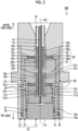
- Fig. 2 is a view showing another example of the clearance sensor according to the present embodiment.
- Fig. 2 shows an example of a cross-sectional configuration cut along a plane passing through the central axis AX.
- a configuration in which the electrode members 10 and the insulation members 20 are locked to each other with pins inserted between the electrode members 10 and the insulation members 20 may also be adopted.
- pins 41 are disposed between the detection electrode 11 and the first insulation member 21.
- the pins 41 penetrate between the outer peripheral surface of the detection electrode 11 and the recess portion 11d and are disposed so as to be inserted into an outer periphery of the protrusion portion 21b of the first insulation member 21. Since the pins 41 are disposed, relative movement of the detection electrode 11 and the first insulation member 21 in the axial direction along the central axis AX and the direction around the central axis AX is restricted.
- pins 42 are disposed between the guard electrode 12 and the first insulation member 21.
- the pins 42 penetrate between the outer peripheral surface of the guard electrode 12 and the recess portion 12d and are disposed so as to be inserted into an outer periphery of the protrusion portion 21c of the first insulation member 21. Since the pins 42 are disposed, relative movement of the guard electrode 12 and the first insulation member 21 in the axial direction along the central axis AX and the direction around the central axis AX is restricted.
- pins 43 are disposed between the guard electrode 12 and the second insulation member 22.
- the pins 43 penetrate between the outer peripheral surface of the guard electrode 12 and the recess portion 12g and are disposed so as to be inserted into an outer periphery of the protrusion portion 22b of the second insulation member 22. Since the pins 43 are disposed, relative movement of the guard electrode 12 and the second insulation member 22 in the axial direction along the central axis AX and the direction around the central axis AX is restricted.
- pins 44 are disposed between the ground electrode 13 and the second insulation member 22.
- the pins 44 penetrate between the outer peripheral surface of the ground electrode 13 and the recess portion 13d and are disposed so as to be inserted into an outer periphery of the protrusion portion 22c of the second insulation member 22. Since the pins 44 are disposed, relative movement of the ground electrode 13 and the second insulation member 22 in the axial direction along the central axis AX and the direction around the central axis AX is restricted.
- a plurality of the pins 41, 42, 43, and 44 are disposed, for example, in the direction around the central axis AX.
- the pins 41, 42, 43, and 44 are formed of, for example, metal or an alloy as with the electrode members 10. Note that, the pins 41, 42, 43, and 44 may be formed by using an insulator such as ceramics as with the insulation members 20.
- the electrode members 10 and the insulation members 20 are locked to each other by means of insertion of the pins 41, 42, 43, and 44. Therefore, the positional deviation between the electrode members 10 and the insulation members 20 can be suppressed in both of the axial direction along the central axis AX and the direction around the central axis AX.
- Fig. 3 is a view showing another example of the clearance sensor according to the present embodiment.
- the clearance sensor 300 shown in Fig. 3 has a configuration in which spacer members formed of an insulator such as alumina are disposed between the detection electrode 11 and the guard electrode 12 and between the guard electrode 12 and the ground electrode 13.
- Other configurations are the same as the above-described configurations (configurations shown in Fig. 1 ).
- a spacer member 31 is disposed between the detection electrode 11 and the guard cylindrical portion 12a of the guard electrode 12.
- the spacer member 31 has, for example, a ring-like shape. However, the shape thereof is not limited thereto and another shape may also be adopted. Since the spacer member 31 is disposed, positional deviation between the detection electrode 11 and the guard cylindrical portion 12a is suppressed. In a configuration shown in Fig. 3 , recess portions for accommodation of the spacer member 31 may be provided at an outer periphery of the detection electrode 11 and an inner periphery of the guard cylindrical portion 12a, respectively.
- each of the detection electrode 11 and the guard cylindrical portion 12a includes a tapered diameter reduction portion of which the diameter decreases toward the tip side and the spacer member 31 is disposed between the diameter reduction portion of the detection electrode 11 and the diameter reduction portion of the guard cylindrical portion 12a may also be adopted. Accordingly, positional deviation of the spacer member 31 is suppressed.
- a spacer member 32 is disposed between the guard cylindrical portion 12a of the guard electrode 12 and the ground cylindrical portion 13a of the ground electrode 13.
- the spacer member 32 has, for example, a ring-like shape. However, the shape thereof is not limited thereto and another shape may also be adopted. Since the spacer member 32 is disposed, positional deviation between the guard cylindrical portion 12a and the ground cylindrical portion 13a is suppressed. In a configuration shown in Fig. 3 , recess portions for accommodation of the spacer member 32 may be provided at an outer periphery of the guard cylindrical portion 12a and an inner periphery of the ground cylindrical portion 13a, respectively.
- each of the guard cylindrical portion 12a and the ground cylindrical portion 13a includes a tapered diameter reduction portion of which the diameter decreases toward the tip side and the spacer member 32 is disposed between the diameter reduction portion of the guard cylindrical portion 12a and the diameter reduction portion of the ground cylindrical portion 13a may also be adopted. Accordingly, positional deviation of the spacer member 32 is suppressed.
- the spacer members 31 and 32 are disposed between the detection electrode 11 and the guard electrode 12 and between the guard electrode 12 and the ground electrode 13, so that positional deviation between the detection electrode 11 and the guard cylindrical portion 12a of the guard electrode 12 and positional deviation between the guard cylindrical portion 12a of the guard electrode 12 and the ground cylindrical portion 13a of the ground electrode 13 can be suppressed.
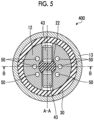
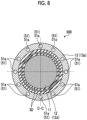
- Fig. 4 is a view showing another example of the clearance sensor according to the present embodiment.
- Fig. 5 shows a configuration as seen in a cross section taken along line A-A in Fig. 4 .
- Fig. 6 shows a configuration as seen in a cross section taken along line B-B in Fig. 5 .
- a clearance sensor 400 shown in Figs. 4 to 6 has a configuration in which a cooling flow path is provided.
- Other configurations are the same as the above-described configuration (configuration shown in Fig. 2 ).
- the present disclosure is not limited thereto, and the other configurations may be the same as the above-described configurations shown in Fig. 1 .
- cooling flow paths 50 penetrate the electrode members 10 and the insulation members 20 in the axial direction along the central axis AX.
- a plurality of the cooling flow paths 50 are disposed on a concentric circle centered on the central axis AX as seen in the axial direction along the central axis AX.
- Each cooling flow path 50 is formed to be linear along the axial direction along the central axis AX.
- the cooling flow paths 50 are positioned to penetrate the ground base portion 13b of the ground electrode 13, the base portion 22a of the second insulation member 22, the guard base portion 12b of the guard electrode 12, the base portion 21a of the first insulation member 21, and the detection electrode 11. As described above, the cooling flow paths 50 are provided at portions corresponding to the respective base portions of the electrode members 10 and the insulation members 20.
- cooling air or the like can be caused to flow through the cooling flow paths 50.
- the cooling air can be caused to flow from the base end side to the tip side of the cooling flow paths 50.
- Fig. 7 is a view showing another example of the clearance sensor according to the present embodiment.
- Fig. 8 shows a configuration as seen in a cross section taken along line C-C in Fig. 7 .
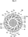
- Fig. 9 shows a configuration as seen in a cross section taken along line D-D in Fig. 7 .
- a clearance sensor 500 shown in Figs. 7 to 9 has a configuration in which cooling flow paths 51 different from the above-described cooling flow paths shown in Figs. 4 to 6 are provided.
- Other configurations are the same as the above-described configuration (configuration shown in Fig. 2 ).
- the present disclosure is not limited thereto, and the other configurations may be the same as the above-described configurations shown in Fig. 1 .
- each of the cooling flow paths 51 includes a linear portion 51a, a convergence portion 51b, and an opening portion 51c.
- the linear portion 51a extends in the axial direction along the central axis AX inside, for example, the ground cylindrical portion 13a of the ground electrode 13.
- a flange portion 13g is provided on the outer periphery of the ground cylindrical portion 13a.
- the diameter of a tip side of the flange portion 13g of the ground cylindrical portion 13a is larger than the diameter of a base end side of the flange portion 13g.
- the linear portion 51a extends in the axial direction along the central axis AX from a base end side end surface of the flange portion 13g to an inner portion of the ground cylindrical portion 13a.
- the linear portion 51a is connected to the convergence portion 51b at a tip side of the ground cylindrical portion 13a.
- a plurality of the linear portions 51a are disposed along a circumferential direction of the ground cylindrical portion 13a.
- the plurality of linear portions 51a are disposed at the same pitch in the circumferential direction of the ground cylindrical portion 13a, for example.
- the convergence portion 51b extends from the tip side of the ground cylindrical portion 13a toward a radial inner side. As shown in Fig. 7 , the convergence portion 51b extends in a direction inclined toward the central axis AX over a range from a connection portion between the convergence portion 51b and the linear portion 51a to the tip side. In addition, as shown in Fig. 9 , the convergence portion 51b extends in a direction tangent to the opening portion 51c from the connection portion between the convergence portion 51b and the linear portion 51a, as seen in the axial direction along the central axis AX.
- the length of the convergence portion 51b can be secured in comparison with a case where a configuration in which the convergence portion 51b extends toward the central axis is adopted. Therefore, the cooling efficiency related to a case where the cooling air is caused to flow is improved.
- the opening portion 51c is disposed at a tip side end portion of the clearance sensor 500.
- the opening portion 51c is formed in an annular shape between the outer periphery of the detection electrode 11 and the guard cylindrical portion 12a of the guard electrode 12.
- cooling air or the like can be caused to flow through the cooling flow paths 51.
- the cooling air flows toward the opening portions 51c via the convergence portions 51b from the linear portions 51a of the cooling flow paths 51 and is discharged to the outside through the opening portions 51c.
- cooling air or the like caused to flow through the cooling flow paths 51, it is possible to efficiently cool the portions corresponding to the respective base portions of the electrode members 10 and the insulation members 20. Accordingly, a temperature rise of the clearance sensor 500 can be suppressed.
- the clearance sensor may have, for example, configurations of both of the cooling flow paths 50 of the clearance sensor 400 shown in Figs. 4 to 6 and the cooling flow paths 51 of the clearance sensor 500 shown in Figs. 7 to 9 . Accordingly, cooling can be performed from an outer peripheral side to an inner side of the clearance sensor and thus the cooling efficiency is improved.
Landscapes
- Physics & Mathematics (AREA)
- General Physics & Mathematics (AREA)
- Investigating Or Analyzing Materials By The Use Of Electric Means (AREA)
- Measurement Of Length, Angles, Or The Like Using Electric Or Magnetic Means (AREA)
Abstract
Description
- The present disclosure relates to a clearance sensor.
- A rotary machine such as an axial compressor including a plurality of rotor blades rotating inside a casing formed in a cylindrical shape is known. In such a type of rotary machine, a tip clearance sensor that measures a tip clearance between the casing and the rotor blade is provided, and the value of the measured tip clearance is maintained to be appropriate. As such a tip clearance sensor, for example, a non-contact type sensor such as a capacitance type sensor is used (see, for example, PTL 1).
- [PTL 1]
Japanese Patent No. 6431665 - The clearance sensor described in PTL 1 has a three-layer structure including a detection electrode, a guard electrode, and a ground electrode of which the central axes are coaxial with each other and insulation layers are disposed between the electrodes. In the case of such a clearance sensor, for example, the insulation layers are attached by means of thermal spraying or the like, and assembly of each electrode is performed along with fit adjustment. As a result, a variation in assembly accuracy becomes great and there may be a decrease in reliability, for example, in a case where the tip clearance is to be measured for a long period of time as described above.
- The present disclosure has been made in view of such circumstances and an object thereof is to provide a clearance sensor with which it is possible to suppress a decrease in long-term measurement reliability.
- According to an aspect of the present disclosure, there is provided a clearance sensor including an electrode member that includes a columnar detection electrode including a detection end surface on one end side in an axial direction along a central axis and that includes a guard electrode and a ground electrode of which central axes are coaxial with the central axis of the detection electrode, an insulation member that connects the detection electrode and the guard electrode to each other and that connects the guard electrode and the ground electrode to each other, and an insulation layer that fills a gap between the detection electrode, the guard electrode, the ground electrode, and the insulation member. The electrode member and the insulation member are locked to each other in at least one of the axial direction along the central axis and a direction around the central axis.
- According to another aspect of the present disclosure, there is provided a clearance sensor including an electrode member that includes a columnar detection electrode including a detection end surface on one end side in an axial direction along a central axis and that includes a guard electrode and a ground electrode of which central axes are coaxial with the central axis of the detection electrode, an insulation member that connects the detection electrode and the guard electrode to each other and that connects the guard electrode and the ground electrode to each other, an insulation layer that fills a gap between the detection electrode, the guard electrode, the ground electrode, and the insulation member, and a cooling flow path that penetrates the electrode member and the insulation member in the axial direction along the central axis. Advantageous Effects of Invention
- According to the aspects of the present disclosure, it is possible to provide a clearance sensor with which it is possible to suppress a decrease in long-term measurement reliability.
-
-
Fig. 1 is a view showing an example of a clearance sensor according to the present embodiment. -
Fig. 2 is a view showing another example of the clearance sensor according to the present embodiment. -
Fig. 3 is a view showing another example of the clearance sensor according to the present embodiment. -
Fig. 4 is a view showing another example of the clearance sensor according to the present embodiment. -
Fig. 5 is a view showing a configuration as seen in a cross section taken along line A-A inFig. 4 . -
Fig. 6 is a view showing a configuration as seen in a cross section taken along line B-B inFig. 5 . -
Fig. 7 is a view showing another example of the clearance sensor according to the present embodiment. -
Fig. 8 is a view showing a configuration as seen in a cross section taken along line C-C inFig. 7 . -
Fig. 9 is a view showing a configuration as seen in a cross section taken along line D-D inFig. 7 . - Hereinafter, an embodiment of a clearance sensor according to the present disclosure will be described with reference to the drawings. Incidentally, the disclosure is not limited by the embodiment. In addition, components in the following embodiment include components that can be easily replaced by those skilled in the art, or components that are substantially the same.
-
Fig. 1 is a view showing an example of aclearance sensor 100 according to the present embodiment.Fig. 1 shows an example of a cross-sectional configuration cut along a plane passing through a central axis AX. Theclearance sensor 100 shown inFig. 1 is a capacitance sensor. Theclearance sensor 100 can be used, for example, in the case of measurement or the like of a tip clearance between a casing and a plurality of rotor blades of an axial compressor that includes the rotor blades rotating inside the casing formed in a cylindrical shape as in the case of a gas turbine or the like. Theclearance sensor 100 includeselectrode members 10,insulation members 20, andinsulation layers 30. - The
electrode members 10 include adetection electrode 11, aguard electrode 12, and aground electrode 13. Theelectrode members 10 are formed of, for example, metal or alloy such as stainless steel. The central axes AX of thedetection electrode 11, theguard electrode 12, and theground electrode 13 are coaxial with each other and thedetection electrode 11, theguard electrode 12, and theground electrode 13 are provided to form three layers arranged in a radial direction. - The
detection electrode 11 is a columnar electrode centered on the central axis AX. Thedetection electrode 11 includes adetection end surface 11a at one end in an axial direction along the central axis AX. Hereinafter, thedetection end surface 11a side in the axial direction along the central axis AX may be referred to as a tip side and a side opposite to thedetection end surface 11a side may be referred to as a base end side in a case where the positional relationship of theclearance sensor 100 is to be described. Theclearance sensor 100 measures a tip clearance in a state where thedetection end surface 11a is disposed at a corresponding position on an inner peripheral surface of a casing. - The
detection electrode 11 is connected to, for example, an inorganic insulation (MI) cable. The MI cable includes awire portion 14, atubular member 15, and atubular component 16. Thewire portion 14, thetubular member 15, and thetubular component 16 of the MI cable form a three-layer structure, and insulators such as magnesium oxide fill gaps between the components. Thewire portion 14 is bonded to thedetection electrode 11 through welding or the like. Thewire portion 14 is disposed to extend from thedetection electrode 11 to the other end side in the axial direction along the central axis AX. Thewire portion 14 is connected to a processing device (not shown) or the like. Thewire portion 14 can be disposed on, for example, the central axis AX. Thetubular member 15 is bonded to aguard base portion 12b, which will be described later, through welding or the like. Thetubular component 16 is bonded to aground base portion 13b, which will be described later, through welding or the like. - The
detection electrode 11 includes arecess portion 11d at anend surface 11b on the base end side. Therecess portion 11d has a shape obtained by hollowing out theend surface 11b in a columnar shape extending toward the tip side. The inner peripheral surface of therecess portion 11d is a cylindrical surface. Ascrew thread 11e is formed on the inner peripheral surface of therecess portion 11d. Thescrew thread 11e is spirally formed on the inner peripheral surface of therecess portion 11d from the base end side to the tip side. - The
guard electrode 12 includes a guardcylindrical portion 12a that is centered on the central axis AX and that has a cylindrical shape and theguard base portion 12b that is centered on the central axis AX and that has a columnar shape. The central axis of theguard electrode 12 is coaxial with the central axis of thedetection electrode 11. - The guard
cylindrical portion 12a surrounds an outerperipheral surface 11c of thedetection electrode 11. The guardcylindrical portion 12a is disposed with a predetermined gap provided between the guardcylindrical portion 12a and the outerperipheral surface 11c of thedetection electrode 11. A tip side end surface of the guardcylindrical portion 12a is flush with thedetection end surface 11a of thedetection electrode 11. - The
guard base portion 12b is disposed on the other end side in the axial direction along the central axis AX with respect to thedetection electrode 11. Theguard base portion 12b is connected to the guardcylindrical portion 12a through, for example, welding or the like. - The
guard base portion 12b includes arecess portion 12d at anend surface 12c on the tip side. Therecess portion 12d has a shape obtained by hollowing out theend surface 12c in a columnar shape extending toward the base end side. The inner peripheral surface of therecess portion 12d is a cylindrical surface. Ascrew thread 12e is formed on the inner peripheral surface of therecess portion 12d. Thescrew thread 12e is spirally formed on the inner peripheral surface of therecess portion 12d from the tip side to the base end side. - The
guard base portion 12b includes arecess portion 12g at anend surface 12f on the base end side. Therecess portion 12g has a shape obtained by hollowing out theend surface 12f in a columnar shape extending toward the base end side. The inner peripheral surface of therecess portion 12g is a cylindrical surface. Ascrew thread 12h is formed on the inner peripheral surface of therecess portion 12g. Thescrew thread 12h is spirally formed on the inner peripheral surface of therecess portion 12g from the tip side to the base end side. - The
ground electrode 13 includes a groundcylindrical portion 13a that is centered on the central axis AX and that has a cylindrical shape and theground base portion 13b that is centered on the central axis AX and that has a columnar shape. The central axis of theground electrode 13 is coaxial with the central axes of thedetection electrode 11 and theguard electrode 12. - The ground
cylindrical portion 13a surrounds an outer peripheral surface of theguard electrode 12. The groundcylindrical portion 13a is disposed with a predetermined gap provided between the groundcylindrical portion 13a and the outer peripheral surface of theguard electrode 12. A tip side end surface of the groundcylindrical portion 13a is flush with thedetection end surface 11a of thedetection electrode 11 and a tip side end surface of the guardcylindrical portion 12a. - The
ground base portion 13b is disposed on the other end side in the axial direction along the central axis AX with respect to theguard electrode 12. Theground base portion 13b is connected to the groundcylindrical portion 13a through, for example, welding or the like. - The
ground base portion 13b includes arecess portion 13d at anend surface 13c on the tip side. Therecess portion 13d has a shape obtained by hollowing out theend surface 13c in a columnar shape extending toward the base end side. The inner peripheral surface of therecess portion 13d is a cylindrical surface. Ascrew thread 13e is formed on the inner peripheral surface of therecess portion 13d. Thescrew thread 13e is spirally formed on the inner peripheral surface of therecess portion 13d from the tip side to the base end side. - The
insulation members 20 connect thedetection electrode 11 and theguard electrode 12 to each other and connect theguard electrode 12 and theground electrode 13 to each other. Theinsulation members 20 include afirst insulation member 21 and asecond insulation member 22. Thefirst insulation member 21 and thesecond insulation member 22 are formed of insulators such as ceramics. - The
first insulation member 21 is disposed between thedetection electrode 11 and theguard base portion 12b in the axial direction along the central axis AX. Thefirst insulation member 21 connects thedetection electrode 11 and theguard base portion 12b to each other in the axial direction. - The
first insulation member 21 has abase portion 21a andprotrusion portions base portion 21a has a columnar shape centered on the central axis AX. Theprotrusion portion 21b protrudes from thebase portion 21a toward the tip side. Theprotrusion portion 21c protrudes from thebase portion 21a to the base end side. Each of theprotrusion portions base portion 21a, for example. The diameter of theprotrusion portion 21b is set such that theprotrusion portion 21b can be inserted into therecess portion 11d of thedetection electrode 11 described above. An outer peripheral surface of theprotrusion portion 21b is a cylindrical surface. Ascrew thread 21d is formed on the outer peripheral surface of theprotrusion portion 21b. Thescrew thread 21d is spirally formed on the outer peripheral surface of theprotrusion portion 21b from the base end side to the tip side such that thescrew thread 21d is screw-bonded to thescrew thread 11e of therecess portion 11d of thedetection electrode 11 described above. Theprotrusion portion 21b is inserted into therecess portion 11d of thedetection electrode 11 in a state where thescrew thread 21d and thescrew thread 11e are screw-bonded to each other. In this manner, thefirst insulation member 21 is screw-bonded to thedetection electrode 11. - Meanwhile, the diameter of the
protrusion portion 21c is set such that theprotrusion portion 21c can be inserted into therecess portion 12d of theguard electrode 12 described above. An outer peripheral surface of theprotrusion portion 21c is a cylindrical surface. Ascrew thread 21e is formed on the outer peripheral surface of theprotrusion portion 21c. Thescrew thread 21e is spirally formed on the outer peripheral surface of theprotrusion portion 21c from the base end side to the tip side such that thescrew thread 21e is screw-bonded to thescrew thread 12e of therecess portion 12d of theguard electrode 12 described above. Theprotrusion portion 21c is inserted into therecess portion 12d of theguard electrode 12 in a state where thescrew thread 21e and thescrew thread 12e are screw-bonded to each other. In this manner, thefirst insulation member 21 is screw-bonded to theguard electrode 12. - The
second insulation member 22 is disposed between theguard base portion 12b and theground base portion 13b in the axial direction along the central axis AX. Thesecond insulation member 22 connects theguard base portion 12b and theground base portion 13b to each other in the axial direction. - The
second insulation member 22 has abase portion 22a andprotrusion portions base portion 22a has a columnar shape centered on the central axis AX. Theprotrusion portion 22b protrudes from thebase portion 22a toward the tip side. Theprotrusion portion 22c protrudes from thebase portion 22a to the base end side. Each of theprotrusion portions base portion 22a, for example. The diameter of theprotrusion portion 22b is set such that theprotrusion portion 22b can be inserted into therecess portion 12g of theguard electrode 12 described above. An outer peripheral surface of theprotrusion portion 22b is a cylindrical surface. Ascrew thread 22d is formed on the outer peripheral surface of theprotrusion portion 22b. Thescrew thread 22d is spirally formed on the outer peripheral surface of theprotrusion portion 22b from the base end side to the tip side such that thescrew thread 22d is screw-bonded to thescrew thread 12h of therecess portion 12g of theguard electrode 12 described above. Theprotrusion portion 22b is inserted into therecess portion 12g of theguard electrode 12 in a state where thescrew thread 22d and thescrew thread 12h are screw-bonded to each other. In this manner, thesecond insulation member 22 is screw-bonded to theguard electrode 12. - Meanwhile, the diameter of the
protrusion portion 22c is set such that theprotrusion portion 22c can be inserted into therecess portion 13d of theground electrode 13 described above. An outer peripheral surface of theprotrusion portion 22c is a cylindrical surface. Ascrew thread 22e is formed on the outer peripheral surface of theprotrusion portion 22c. Thescrew thread 22e is spirally formed on the outer peripheral surface of theprotrusion portion 22c from the base end side to the tip side such that thescrew thread 22e is screw-bonded to thescrew thread 13e of therecess portion 13d of theground electrode 13 described above. Theprotrusion portion 22c is inserted into therecess portion 13d of theground electrode 13 in a state where thescrew thread 22e and thescrew thread 13e are screw-bonded to each other. In this way, thesecond insulation member 22 is screw-bonded to theground electrode 13. - As described above, the
electrode members 10 and theinsulation members 20 are locked to each other in at least one of the axial direction along the central axis AX and a direction around the central axis AX with therecess portion 11d of thedetection electrode 11 being screw-bonded to theprotrusion portion 21b of thefirst insulation member 21, theprotrusion portion 21c of thefirst insulation member 21 being screw-bonded to therecess portion 12d of theguard electrode 12, therecess portion 12g of theguard electrode 12 being screw-bonded to theprotrusion portion 22b of thesecond insulation member 22, and theprotrusion portion 22c of thesecond insulation member 22 being screw-bonded to therecess portion 13d of theground electrode 13. - For the insulation layers 30, for example, a ceramic-based insulating adhesive agent or the like is used. The insulation layers 30 fill gaps between the
detection electrode 11, theguard electrode 12, theground electrode 13, and the insulation members 20 (thefirst insulation member 21 and the second insulation member 22). Since the insulation layers 30 are disposed, it is possible to insulate thedetection electrode 11, theguard electrode 12, and theground electrode 13 from each other and to suppress relative rotational movement in the direction around the central axis AX. In addition, the insulation layers 30 are disposed to fill a gap between screw parts or the like between thefirst insulation member 21 and thedetection electrode 11, between thefirst insulation member 21 and theguard electrode 12, between thesecond insulation member 22 and theguard electrode 12, and between thesecond insulation member 22 and theground electrode 13. Accordingly, relative rotational movement of each component can be suppressed. - As described above, the
clearance sensor 100 according to the present embodiment includes theelectrode members 10 that include thecolumnar detection electrode 11 including the detection end surface on one end side in the axial direction along the central axis AX and that include theguard electrode 12 and theground electrode 13 of which the central axes AX are coaxial with the central axis AX of thedetection electrode 11, theinsulation members 20 that connect thedetection electrode 11 and theguard electrode 12 to each other and that connect theguard electrode 12 and theground electrode 13 to each other, and the insulation layers 30 that fill gaps between thedetection electrode 11, theguard electrode 12, theground electrode 13, and theinsulation members 20. Theelectrode members 10 and theinsulation members 20 are locked to each other in at least one of the axial direction along the central axis AX and the direction around the central axis AX. - In this configuration, the
electrode members 10 and theinsulation members 20 are locked to each other so that positional deviation between theelectrode members 10 and theinsulation members 20 can be suppressed. Therefore, it is possible to suppress a decrease in long-term measurement reliability. In addition, in a case where long-term measurement is performed at a high temperature as in a case where a tip clearance between a casing of a gas turbine and a rotor blade is measured, wear of theinsulation members 20 and delamination of the insulation layers 30 caused by a thermal elongation difference and vibrations can be suppressed and thus reliability can be maintained for a long period of time. - In addition, in the
clearance sensor 100 according to the present embodiment, theguard electrode 12 includes the guardcylindrical portion 12a that surrounds the outer peripheral surface of thedetection electrode 11 and theguard base portion 12b that is disposed on the base end side in the axial direction with respect to thedetection electrode 11 and that is connected to the guardcylindrical portion 12a, theground electrode 13 includes the groundcylindrical portion 13a that surrounds the outer peripheral surface of theguard electrode 12 and theground base portion 13b that is disposed on the base end side with respect to theguard electrode 12 and that is connected to the groundcylindrical portion 13a, and theinsulation members 20 include thefirst insulation member 21 that connects thedetection electrode 11 and theguard base portion 12b to each other in the axial direction and thesecond insulation member 22 that connects theguard base portion 12b and theground base portion 13b to each other in the axial direction. Therefore, since the base portions of the respective electrodes constituting theelectrode members 10 are connected to each other by theinsulation members 20 and connection portions are locked, positional deviation between theelectrode members 10 and theinsulation members 20 can be more reliably suppressed. - In addition, in the
clearance sensor 100 according to the present embodiment, theelectrode members 10 and theinsulation members 20 are locked to each other by being screw-bonded to each other. Therefore, the positional deviation between theelectrode members 10 and theinsulation members 20 can be suppressed in both of the axial direction along the central axis AX and the direction around the central axis AX. - In the above-described example shown in
Fig. 1 , a configuration in which theelectrode members 10 and theinsulation members 20 are locked to each other by being screw-bonded to each other has been described as an example. However, a configuration in which theelectrode members 10 and theinsulation members 20 are locked to each other is not limited to a configuration in which theelectrode members 10 and theinsulation members 20 are locked to each other by being screw-bonded to each other. -
Fig. 2 is a view showing another example of the clearance sensor according to the present embodiment.Fig. 2 shows an example of a cross-sectional configuration cut along a plane passing through the central axis AX. For example, as in the case of aclearance sensor 200 inFig. 2 , a configuration in which theelectrode members 10 and theinsulation members 20 are locked to each other with pins inserted between theelectrode members 10 and theinsulation members 20 may also be adopted. - In an example shown in
Fig. 2 , pins 41 are disposed between thedetection electrode 11 and thefirst insulation member 21. Thepins 41 penetrate between the outer peripheral surface of thedetection electrode 11 and therecess portion 11d and are disposed so as to be inserted into an outer periphery of theprotrusion portion 21b of thefirst insulation member 21. Since thepins 41 are disposed, relative movement of thedetection electrode 11 and thefirst insulation member 21 in the axial direction along the central axis AX and the direction around the central axis AX is restricted. - In addition, pins 42 are disposed between the
guard electrode 12 and thefirst insulation member 21. Thepins 42 penetrate between the outer peripheral surface of theguard electrode 12 and therecess portion 12d and are disposed so as to be inserted into an outer periphery of theprotrusion portion 21c of thefirst insulation member 21. Since thepins 42 are disposed, relative movement of theguard electrode 12 and thefirst insulation member 21 in the axial direction along the central axis AX and the direction around the central axis AX is restricted. - In addition, pins 43 are disposed between the
guard electrode 12 and thesecond insulation member 22. Thepins 43 penetrate between the outer peripheral surface of theguard electrode 12 and therecess portion 12g and are disposed so as to be inserted into an outer periphery of theprotrusion portion 22b of thesecond insulation member 22. Since thepins 43 are disposed, relative movement of theguard electrode 12 and thesecond insulation member 22 in the axial direction along the central axis AX and the direction around the central axis AX is restricted. - In addition, pins 44 are disposed between the
ground electrode 13 and thesecond insulation member 22. Thepins 44 penetrate between the outer peripheral surface of theground electrode 13 and therecess portion 13d and are disposed so as to be inserted into an outer periphery of theprotrusion portion 22c of thesecond insulation member 22. Since thepins 44 are disposed, relative movement of theground electrode 13 and thesecond insulation member 22 in the axial direction along the central axis AX and the direction around the central axis AX is restricted. - A plurality of the
pins pins electrode members 10. Note that, thepins insulation members 20. - As described above, in the
clearance sensor 200 according to the present embodiment, theelectrode members 10 and theinsulation members 20 are locked to each other by means of insertion of thepins electrode members 10 and theinsulation members 20 can be suppressed in both of the axial direction along the central axis AX and the direction around the central axis AX. -
Fig. 3 is a view showing another example of the clearance sensor according to the present embodiment. Theclearance sensor 300 shown inFig. 3 has a configuration in which spacer members formed of an insulator such as alumina are disposed between thedetection electrode 11 and theguard electrode 12 and between theguard electrode 12 and theground electrode 13. Other configurations are the same as the above-described configurations (configurations shown inFig. 1 ). - As shown in
Fig. 3 , aspacer member 31 is disposed between thedetection electrode 11 and the guardcylindrical portion 12a of theguard electrode 12. Thespacer member 31 has, for example, a ring-like shape. However, the shape thereof is not limited thereto and another shape may also be adopted. Since thespacer member 31 is disposed, positional deviation between thedetection electrode 11 and the guardcylindrical portion 12a is suppressed. In a configuration shown inFig. 3 , recess portions for accommodation of thespacer member 31 may be provided at an outer periphery of thedetection electrode 11 and an inner periphery of the guardcylindrical portion 12a, respectively. In addition, a configuration in which each of thedetection electrode 11 and the guardcylindrical portion 12a includes a tapered diameter reduction portion of which the diameter decreases toward the tip side and thespacer member 31 is disposed between the diameter reduction portion of thedetection electrode 11 and the diameter reduction portion of the guardcylindrical portion 12a may also be adopted. Accordingly, positional deviation of thespacer member 31 is suppressed. - A
spacer member 32 is disposed between the guardcylindrical portion 12a of theguard electrode 12 and the groundcylindrical portion 13a of theground electrode 13. Thespacer member 32 has, for example, a ring-like shape. However, the shape thereof is not limited thereto and another shape may also be adopted. Since thespacer member 32 is disposed, positional deviation between the guardcylindrical portion 12a and the groundcylindrical portion 13a is suppressed. In a configuration shown inFig. 3 , recess portions for accommodation of thespacer member 32 may be provided at an outer periphery of the guardcylindrical portion 12a and an inner periphery of the groundcylindrical portion 13a, respectively. In addition, a configuration in which each of the guardcylindrical portion 12a and the groundcylindrical portion 13a includes a tapered diameter reduction portion of which the diameter decreases toward the tip side and thespacer member 32 is disposed between the diameter reduction portion of the guardcylindrical portion 12a and the diameter reduction portion of the groundcylindrical portion 13a may also be adopted. Accordingly, positional deviation of thespacer member 32 is suppressed. - As described above, in the
clearance sensor 300 according to the present embodiment, thespacer members detection electrode 11 and theguard electrode 12 and between theguard electrode 12 and theground electrode 13, so that positional deviation between thedetection electrode 11 and the guardcylindrical portion 12a of theguard electrode 12 and positional deviation between the guardcylindrical portion 12a of theguard electrode 12 and the groundcylindrical portion 13a of theground electrode 13 can be suppressed. -
Fig. 4 is a view showing another example of the clearance sensor according to the present embodiment.Fig. 5 shows a configuration as seen in a cross section taken along line A-A inFig. 4 .Fig. 6 shows a configuration as seen in a cross section taken along line B-B inFig. 5 . Aclearance sensor 400 shown inFigs. 4 to 6 has a configuration in which a cooling flow path is provided. Other configurations are the same as the above-described configuration (configuration shown inFig. 2 ). However, the present disclosure is not limited thereto, and the other configurations may be the same as the above-described configurations shown inFig. 1 . - As shown in
Figs. 5 and6 , coolingflow paths 50 penetrate theelectrode members 10 and theinsulation members 20 in the axial direction along the central axis AX. A plurality of thecooling flow paths 50 are disposed on a concentric circle centered on the central axis AX as seen in the axial direction along the central axis AX. Each coolingflow path 50 is formed to be linear along the axial direction along the central axis AX. - In an example shown in
Figs. 5 and6 , for example, thecooling flow paths 50 are positioned to penetrate theground base portion 13b of theground electrode 13, thebase portion 22a of thesecond insulation member 22, theguard base portion 12b of theguard electrode 12, thebase portion 21a of thefirst insulation member 21, and thedetection electrode 11. As described above, thecooling flow paths 50 are provided at portions corresponding to the respective base portions of theelectrode members 10 and theinsulation members 20. - For example, cooling air or the like can be caused to flow through the
cooling flow paths 50. For example, the cooling air can be caused to flow from the base end side to the tip side of thecooling flow paths 50. By means of cooling air or the like caused to flow through thecooling flow paths 50, it is possible to efficiently cool the portions corresponding to the respective base portions of theelectrode members 10 and theinsulation members 20. Accordingly, a temperature rise of theclearance sensor 400 can be suppressed. - Note that, in the example shown in
Figs. 4 to 6 , a case where a configuration, in which theelectrode members 10 and theinsulation members 20 are locked as shown inFig. 1 orFig. 2 , is adopted has been described. However, the present disclosure is not limited thereto. For example, a configuration in which theelectrode members 10 and theinsulation members 20 are not formed and connection is achieved by means of, for example, fitting or the like may also be adopted. -
Fig. 7 is a view showing another example of the clearance sensor according to the present embodiment.Fig. 8 shows a configuration as seen in a cross section taken along line C-C inFig. 7 .Fig. 9 shows a configuration as seen in a cross section taken along line D-D inFig. 7 . Aclearance sensor 500 shown inFigs. 7 to 9 has a configuration in whichcooling flow paths 51 different from the above-described cooling flow paths shown inFigs. 4 to 6 are provided. Other configurations are the same as the above-described configuration (configuration shown inFig. 2 ). However, the present disclosure is not limited thereto, and the other configurations may be the same as the above-described configurations shown inFig. 1 . - In an example shown in
Figs. 7 to 9 , each of thecooling flow paths 51 includes alinear portion 51a, aconvergence portion 51b, and anopening portion 51c. Thelinear portion 51a extends in the axial direction along the central axis AX inside, for example, the groundcylindrical portion 13a of theground electrode 13. As shown inFig. 7 , aflange portion 13g is provided on the outer periphery of the groundcylindrical portion 13a. The diameter of a tip side of theflange portion 13g of the groundcylindrical portion 13a is larger than the diameter of a base end side of theflange portion 13g. Thelinear portion 51a extends in the axial direction along the central axis AX from a base end side end surface of theflange portion 13g to an inner portion of the groundcylindrical portion 13a. Thelinear portion 51a is connected to theconvergence portion 51b at a tip side of the groundcylindrical portion 13a. As shown inFig. 8 , a plurality of thelinear portions 51a are disposed along a circumferential direction of the groundcylindrical portion 13a. The plurality oflinear portions 51a are disposed at the same pitch in the circumferential direction of the groundcylindrical portion 13a, for example. - The
convergence portion 51b extends from the tip side of the groundcylindrical portion 13a toward a radial inner side. As shown inFig. 7 , theconvergence portion 51b extends in a direction inclined toward the central axis AX over a range from a connection portion between theconvergence portion 51b and thelinear portion 51a to the tip side. In addition, as shown inFig. 9 , theconvergence portion 51b extends in a direction tangent to theopening portion 51c from the connection portion between theconvergence portion 51b and thelinear portion 51a, as seen in the axial direction along the central axis AX. Since a configuration in which theconvergence portion 51b extends in the direction tangent to theopening portion 51c from the as seen in the axial direction along the central axis AX is adopted, the length of theconvergence portion 51b can be secured in comparison with a case where a configuration in which theconvergence portion 51b extends toward the central axis is adopted. Therefore, the cooling efficiency related to a case where the cooling air is caused to flow is improved. - The opening
portion 51c is disposed at a tip side end portion of theclearance sensor 500. The openingportion 51c is formed in an annular shape between the outer periphery of thedetection electrode 11 and the guardcylindrical portion 12a of theguard electrode 12. - For example, cooling air or the like can be caused to flow through the
cooling flow paths 51. For example, the cooling air flows toward the openingportions 51c via theconvergence portions 51b from thelinear portions 51a of thecooling flow paths 51 and is discharged to the outside through the openingportions 51c. By means of cooling air or the like caused to flow through thecooling flow paths 51, it is possible to efficiently cool the portions corresponding to the respective base portions of theelectrode members 10 and theinsulation members 20. Accordingly, a temperature rise of theclearance sensor 500 can be suppressed. - Note that, in the example shown in
Figs. 7 to 9 , a case where a configuration, in which theelectrode members 10 and theinsulation members 20 are locked as shown inFig. 1 orFig. 2 , is adopted has been described. However, the present disclosure is not limited thereto. For example, a configuration in which theelectrode members 10 and theinsulation members 20 are not formed and connection is achieved by means of, for example, fitting or the like may also be adopted. - In addition, the clearance sensor may have, for example, configurations of both of the
cooling flow paths 50 of theclearance sensor 400 shown inFigs. 4 to 6 and thecooling flow paths 51 of theclearance sensor 500 shown inFigs. 7 to 9 . Accordingly, cooling can be performed from an outer peripheral side to an inner side of the clearance sensor and thus the cooling efficiency is improved. -
- 10: Electrode member
- 11: Detection electrode
- 11a: Detection end surface
- 11b, 12c, 12f, 13c: End surface
- 11c: Outer peripheral surface
- 11d, 12d, 12g, 13d: Recess portion
- 11e, 12e, 12h, 13e, 21d, 21e, 22d, 22e: Screw thread 11f, 12i, 13f: Diameter reduction portion
- 12: Guard electrode
- 12a: Guard cylindrical portion
- 12b: Guard base portion
- 13: Ground electrode
- 13a: Ground cylindrical portion
- 13b: Ground base portion
- 13g: Flange portion
- 14: Wire portion
- 15: Tubular member
- 16: Tubular component
- 20: Insulation member
- 21: First insulation member
- 21a, 21b: Base portion
- 21b, 21c, 22b, 22c: Protrusion portion
- 22: Second insulation member
- 30: Insulation layer
- 31, 32: Spacer member
- 41, 42, 43, 44: Pin
- 50, 51: Cooling flow path
- 51a: Linear portion
- 51b: Convergence portion
- 51c: Opening portion
- 100, 200, 300, 400, 500: Clearance sensor
- AX: Central axis
Claims (10)
- A clearance sensor comprising:an electrode member that includes a columnar detection electrode including a detection end surface on one end side in an axial direction along a central axis and that includes a guard electrode and a ground electrode of which central axes are coaxial with the central axis of the detection electrode;an insulation member that connects the detection electrode and the guard electrode to each other and that connects the guard electrode and the ground electrode to each other; andan insulation layer that fills a gap between the detection electrode, the guard electrode, the ground electrode, and the insulation member,wherein the electrode member and the insulation member are locked to each other in at least one of the axial direction along the central axis and a direction around the central axis.
- The clearance sensor according to Claim 1,wherein the guard electrode includes a guard cylindrical portion that surrounds an outer peripheral surface of the detection electrode and a guard base portion that is disposed on the other end side opposite to the one end side in the axial direction with respect to the detection electrode and that is connected to the guard cylindrical portion,the ground electrode includes a ground cylindrical portion that surrounds an outer peripheral surface of the guard electrode and a ground base portion that is disposed on the other end side in the axial direction with respect to the guard electrode and that is connected to the ground cylindrical portion, andthe insulation member includes a first insulation member that connects the detection electrode and the guard base portion to each other in the axial direction and a second insulation member that connects the guard base portion and the ground base portion to each other in the axial direction.
- The clearance sensor according to Claim 1 or 2,
wherein the electrode member and the insulation member are locked to each other by being screw-bonded to each other. - The clearance sensor according to any one of Claims 1 to 3,
wherein the electrode member and the insulation member are locked to each other by means of insertion of a pin. - The clearance sensor according to any one of Claims 1 to 4,
wherein a spacer member formed of an insulator is disposed in at least one of a gap between the detection electrode and the guard electrode and a gap between the guard electrode and the ground electrode. - The clearance sensor according to any one of Claims 1 to 5, further comprising:
a cooling flow path that penetrates the electrode member and the insulation member in the axial direction along the central axis. - A clearance sensor comprising:an electrode member that includes a columnar detection electrode including a detection end surface on one end side in an axial direction along a central axis and that includes a guard electrode and a ground electrode of which central axes are coaxial with the central axis of the detection electrode;an insulation member that connects the detection electrode and the guard electrode to each other and that connects the guard electrode and the ground electrode to each other;an insulation layer that fills a gap between the detection electrode, the guard electrode, the ground electrode, and the insulation member; anda cooling flow path that penetrates the electrode member and the insulation member in the axial direction along the central axis.
- The clearance sensor according to Claim 6 or 7,
wherein a plurality of the cooling flow paths are disposed on a concentric circle centered on the central axis as seen in the axial direction along the central axis. - The clearance sensor according to Claim 8,
wherein each cooling flow path is formed to be linear along the axial direction along the central axis. - The clearance sensor according to Claim 8,
wherein the cooling flow paths are formed to gather from an outer side to an inner side in a radial direction with respect to the central axis toward a detection end side.
Applications Claiming Priority (2)
| Application Number | Priority Date | Filing Date | Title |
|---|---|---|---|
| JP2021039173A JP7650685B2 (en) | 2021-03-11 | 2021-03-11 | Clearance Sensor |
| PCT/JP2022/007666 WO2022190887A1 (en) | 2021-03-11 | 2022-02-24 | Clearance sensor |
Publications (3)
| Publication Number | Publication Date |
|---|---|
| EP4276403A1 true EP4276403A1 (en) | 2023-11-15 |
| EP4276403A4 EP4276403A4 (en) | 2024-05-29 |
| EP4276403B1 EP4276403B1 (en) | 2025-11-19 |
Family
ID=83227811
Family Applications (1)
| Application Number | Title | Priority Date | Filing Date |
|---|---|---|---|
| EP22766846.4A Active EP4276403B1 (en) | 2021-03-11 | 2022-02-24 | Clearance sensor |
Country Status (4)
| Country | Link |
|---|---|
| US (1) | US12584724B2 (en) |
| EP (1) | EP4276403B1 (en) |
| JP (1) | JP7650685B2 (en) |
| WO (1) | WO2022190887A1 (en) |
Family Cites Families (24)
| Publication number | Priority date | Publication date | Assignee | Title |
|---|---|---|---|---|
| US2842738A (en) * | 1956-04-05 | 1958-07-08 | Ford Motor Co | Capacitance probe |
| JPS5312661A (en) | 1976-07-21 | 1978-02-04 | Seiko Instr & Electronics Ltd | Contactless switching mechanism for watches |
| JPS5883Y2 (en) * | 1977-03-14 | 1983-01-05 | 岩崎通信機株式会社 | Electrostatic probe for displacement meter |
| JPS5599004A (en) * | 1979-01-25 | 1980-07-28 | Iwatsu Electric Co Ltd | Thickness detector |
| JPS58144215A (en) | 1982-02-19 | 1983-08-27 | Kubota Ltd | Automatic traveling vehicle |
| JPS58144215U (en) * | 1982-03-23 | 1983-09-28 | 岩崎通信機株式会社 | Capacitance probe of displacement meter |
| JPS58197671A (en) | 1982-05-11 | 1983-11-17 | Meidensha Electric Mfg Co Ltd | Framed electrode |
| DE3417868C2 (en) | 1984-05-14 | 1986-08-07 | Deutsche Forschungs- und Versuchsanstalt für Luft- und Raumfahrt e.V., 5000 Köln | Method for controlling robot movements |
| JPS616706U (en) * | 1984-06-20 | 1986-01-16 | 株式会社日立製作所 | Capacitive gap measuring device |
| DE3433351C1 (en) * | 1984-09-11 | 1986-01-02 | MTU Motoren- und Turbinen-Union München GmbH, 8000 München | Capacitive measuring system for measuring the distance between two parts that are movable relative to each other |
| DE3631058A1 (en) | 1986-09-12 | 1988-03-24 | Preh Elektro Feinmechanik | METHOD FOR PRODUCING GUIDANCE AND / OR RESISTANCE TRACKS ON A SUBSTRATE AND POTENTIOMETER PRODUCED BY THIS METHOD |
| JPH0522806Y2 (en) * | 1986-11-04 | 1993-06-11 | ||
| US5119036A (en) * | 1990-05-29 | 1992-06-02 | General Electric Company | Electrical capacitance clearanceometer |
| JPH04297805A (en) * | 1991-01-09 | 1992-10-21 | Kyoto Jushi Seiko Kk | Electrode device in thickness gauge of electrostatic capacitance system and method for assembling this electrode device |
| FR2690244B1 (en) * | 1992-01-10 | 1997-03-21 | Leteurtre Jean | METHOD AND / OR DEVICE FOR IMPLEMENTING THE CAPACITIVE MEASUREMENT PROCESS WHICH CAN TAKE DIMENSIONAL NON-CONTACT AND HIGHLY PRECISION MEASUREMENTS IN AN INDUSTRIAL ENVIRONMENT. |
| JP3442871B2 (en) * | 1994-07-19 | 2003-09-02 | インタクト株式会社 | Apparatus for measuring thickness or displacement using capacitance meter, and method for measuring thickness or displacement using capacitance meter |
| JP2004354269A (en) * | 2003-05-30 | 2004-12-16 | Mitsutsu Kk | Electrostatic capacity probe |
| US20100079136A1 (en) * | 2008-09-29 | 2010-04-01 | Rosemount Aerospace Inc. | Blade tip clearance measurement sensor and method for gas turbine engines |
| US9417048B2 (en) | 2012-10-31 | 2016-08-16 | General Electric Company | Capacitive sensor device and method of manufacture |
| GB2522210B (en) * | 2014-01-16 | 2018-10-10 | Weston Aerospace Ltd | Engine probe |
| JP6383647B2 (en) * | 2014-11-19 | 2018-08-29 | 東京エレクトロン株式会社 | Measuring system and measuring method |
| JP6551096B2 (en) | 2015-09-15 | 2019-07-31 | 株式会社デンソー | Spark plug for internal combustion engine |
| JP6842328B2 (en) | 2017-03-23 | 2021-03-17 | エドワーズ株式会社 | Vacuum pump, main sensor, and thread groove stator |
| CN111043949B (en) * | 2019-12-31 | 2021-04-30 | 电子科技大学 | A device for detection of turbine blade tip clearance |
-
2021
- 2021-03-11 JP JP2021039173A patent/JP7650685B2/en active Active
-
2022
- 2022-02-24 WO PCT/JP2022/007666 patent/WO2022190887A1/en not_active Ceased
- 2022-02-24 EP EP22766846.4A patent/EP4276403B1/en active Active
-
2023
- 2023-08-10 US US18/232,500 patent/US12584724B2/en active Active
Also Published As
| Publication number | Publication date |
|---|---|
| EP4276403B1 (en) | 2025-11-19 |
| US20230384081A1 (en) | 2023-11-30 |
| JP7650685B2 (en) | 2025-03-25 |
| JP2022138980A (en) | 2022-09-26 |
| WO2022190887A1 (en) | 2022-09-15 |
| US12584724B2 (en) | 2026-03-24 |
| EP4276403A4 (en) | 2024-05-29 |
Similar Documents
| Publication | Publication Date | Title |
|---|---|---|
| US8558538B2 (en) | Blade tip clearance measurement sensor for gas turbine engines | |
| US9417048B2 (en) | Capacitive sensor device and method of manufacture | |
| JP6186177B2 (en) | Rotational clearance measurement system and operation method | |
| JP4173915B2 (en) | Capacitance type gap measuring device | |
| WO2011087615A2 (en) | An open circuit wear sensor for use with a conductive wear counterface | |
| US10077992B2 (en) | Tip clearance probe including anti-rotation feature | |
| EP2236977A1 (en) | Time-indicating rub pin for transient clearance measurement and related method | |
| US20230384081A1 (en) | Clearance sensor | |
| US20150016957A1 (en) | Ceramic component for a turbomachine | |
| WO2016199822A1 (en) | Rotary machine | |
| KR102653284B1 (en) | Turbomachinery with SAW or BAW device, measuring equipment and installation method | |
| EP3296686B1 (en) | Tri-axial capacitance probe with case integrated housing | |
| KR101745688B1 (en) | Journal Bearing Capable of Measuring Turbine Rotor Runout | |
| RU2574945C1 (en) | Resilient support of turbomachine rotor | |
| Sheard et al. | Gap Measurement Device | |
| CN109322997A (en) | Seal structure for engine |
Legal Events
| Date | Code | Title | Description |
|---|---|---|---|
| STAA | Information on the status of an ep patent application or granted ep patent |
Free format text: STATUS: THE INTERNATIONAL PUBLICATION HAS BEEN MADE |
|
| PUAI | Public reference made under article 153(3) epc to a published international application that has entered the european phase |
Free format text: ORIGINAL CODE: 0009012 |
|
| STAA | Information on the status of an ep patent application or granted ep patent |
Free format text: STATUS: REQUEST FOR EXAMINATION WAS MADE |
|
| 17P | Request for examination filed |
Effective date: 20230809 |
|
| AK | Designated contracting states |
Kind code of ref document: A1 Designated state(s): AL AT BE BG CH CY CZ DE DK EE ES FI FR GB GR HR HU IE IS IT LI LT LU LV MC MK MT NL NO PL PT RO RS SE SI SK SM TR |
|
| REG | Reference to a national code |
Ref country code: DE Ref legal event code: R079 Free format text: PREVIOUS MAIN CLASS: G01B0007000000 Ipc: G01B0007140000 Ref country code: DE Ref legal event code: R079 Ref document number: 602022025306 Country of ref document: DE Free format text: PREVIOUS MAIN CLASS: G01B0007000000 Ipc: G01B0007140000 |
|
| RIC1 | Information provided on ipc code assigned before grant |
Ipc: G01B 7/14 20060101AFI20240123BHEP |
|
| A4 | Supplementary search report drawn up and despatched |
Effective date: 20240429 |
|
| RIC1 | Information provided on ipc code assigned before grant |
Ipc: G01B 7/14 20060101AFI20240423BHEP |
|
| DAV | Request for validation of the european patent (deleted) | ||
| DAX | Request for extension of the european patent (deleted) | ||
| GRAP | Despatch of communication of intention to grant a patent |
Free format text: ORIGINAL CODE: EPIDOSNIGR1 |
|
| STAA | Information on the status of an ep patent application or granted ep patent |
Free format text: STATUS: GRANT OF PATENT IS INTENDED |
|
| INTG | Intention to grant announced |
Effective date: 20250721 |
|
| GRAS | Grant fee paid |
Free format text: ORIGINAL CODE: EPIDOSNIGR3 |
|
| GRAA | (expected) grant |
Free format text: ORIGINAL CODE: 0009210 |
|
| STAA | Information on the status of an ep patent application or granted ep patent |
Free format text: STATUS: THE PATENT HAS BEEN GRANTED |
|
| AK | Designated contracting states |
Kind code of ref document: B1 Designated state(s): AL AT BE BG CH CY CZ DE DK EE ES FI FR GB GR HR HU IE IS IT LI LT LU LV MC MK MT NL NO PL PT RO RS SE SI SK SM TR |
|
| REG | Reference to a national code |
Ref country code: CH Ref legal event code: F10 Free format text: ST27 STATUS EVENT CODE: U-0-0-F10-F00 (AS PROVIDED BY THE NATIONAL OFFICE) Effective date: 20251119 Ref country code: GB Ref legal event code: FG4D |
|
| REG | Reference to a national code |
Ref country code: DE Ref legal event code: R096 Ref document number: 602022025306 Country of ref document: DE |
|
| REG | Reference to a national code |
Ref country code: IE Ref legal event code: FG4D |
|
| REG | Reference to a national code |
Ref country code: NL Ref legal event code: MP Effective date: 20251119 |
|
| PG25 | Lapsed in a contracting state [announced via postgrant information from national office to epo] |
Ref country code: ES Free format text: LAPSE BECAUSE OF FAILURE TO SUBMIT A TRANSLATION OF THE DESCRIPTION OR TO PAY THE FEE WITHIN THE PRESCRIBED TIME-LIMIT Effective date: 20251119 |
|
| REG | Reference to a national code |
Ref country code: LT Ref legal event code: MG9D |
|
| PG25 | Lapsed in a contracting state [announced via postgrant information from national office to epo] |
Ref country code: NO Free format text: LAPSE BECAUSE OF FAILURE TO SUBMIT A TRANSLATION OF THE DESCRIPTION OR TO PAY THE FEE WITHIN THE PRESCRIBED TIME-LIMIT Effective date: 20260219 |
|
| PGFP | Annual fee paid to national office [announced via postgrant information from national office to epo] |
Ref country code: DE Payment date: 20260227 Year of fee payment: 5 |
|
| PG25 | Lapsed in a contracting state [announced via postgrant information from national office to epo] |
Ref country code: FI Free format text: LAPSE BECAUSE OF FAILURE TO SUBMIT A TRANSLATION OF THE DESCRIPTION OR TO PAY THE FEE WITHIN THE PRESCRIBED TIME-LIMIT Effective date: 20251119 Ref country code: HR Free format text: LAPSE BECAUSE OF FAILURE TO SUBMIT A TRANSLATION OF THE DESCRIPTION OR TO PAY THE FEE WITHIN THE PRESCRIBED TIME-LIMIT Effective date: 20251119 Ref country code: AT Free format text: LAPSE BECAUSE OF FAILURE TO SUBMIT A TRANSLATION OF THE DESCRIPTION OR TO PAY THE FEE WITHIN THE PRESCRIBED TIME-LIMIT Effective date: 20251119 |
|
| PGFP | Annual fee paid to national office [announced via postgrant information from national office to epo] |
Ref country code: AT Payment date: 20260301 Year of fee payment: 5 |
|
| REG | Reference to a national code |
Ref country code: AT Ref legal event code: MK05 Ref document number: 1859159 Country of ref document: AT Kind code of ref document: T Effective date: 20251119 |
|
| PG25 | Lapsed in a contracting state [announced via postgrant information from national office to epo] |
Ref country code: NL Free format text: LAPSE BECAUSE OF FAILURE TO SUBMIT A TRANSLATION OF THE DESCRIPTION OR TO PAY THE FEE WITHIN THE PRESCRIBED TIME-LIMIT Effective date: 20251119 |
|
| PG25 | Lapsed in a contracting state [announced via postgrant information from national office to epo] |
Ref country code: RS Free format text: LAPSE BECAUSE OF FAILURE TO SUBMIT A TRANSLATION OF THE DESCRIPTION OR TO PAY THE FEE WITHIN THE PRESCRIBED TIME-LIMIT Effective date: 20260219 |
|
| PG25 | Lapsed in a contracting state [announced via postgrant information from national office to epo] |
Ref country code: IS Free format text: LAPSE BECAUSE OF FAILURE TO SUBMIT A TRANSLATION OF THE DESCRIPTION OR TO PAY THE FEE WITHIN THE PRESCRIBED TIME-LIMIT Effective date: 20260319 |
|
| PG25 | Lapsed in a contracting state [announced via postgrant information from national office to epo] |
Ref country code: PT Free format text: LAPSE BECAUSE OF FAILURE TO SUBMIT A TRANSLATION OF THE DESCRIPTION OR TO PAY THE FEE WITHIN THE PRESCRIBED TIME-LIMIT Effective date: 20260319 |
|
| PG25 | Lapsed in a contracting state [announced via postgrant information from national office to epo] |
Ref country code: PL Free format text: LAPSE BECAUSE OF FAILURE TO SUBMIT A TRANSLATION OF THE DESCRIPTION OR TO PAY THE FEE WITHIN THE PRESCRIBED TIME-LIMIT Effective date: 20251119 |
|
| PG25 | Lapsed in a contracting state [announced via postgrant information from national office to epo] |
Ref country code: LV Free format text: LAPSE BECAUSE OF FAILURE TO SUBMIT A TRANSLATION OF THE DESCRIPTION OR TO PAY THE FEE WITHIN THE PRESCRIBED TIME-LIMIT Effective date: 20251119 |
|
| PG25 | Lapsed in a contracting state [announced via postgrant information from national office to epo] |
Ref country code: BG Free format text: LAPSE BECAUSE OF FAILURE TO SUBMIT A TRANSLATION OF THE DESCRIPTION OR TO PAY THE FEE WITHIN THE PRESCRIBED TIME-LIMIT Effective date: 20251119 |