EP4276266A1 - Stopper assembly - Google Patents
Stopper assembly Download PDFInfo
- Publication number
- EP4276266A1 EP4276266A1 EP23169072.8A EP23169072A EP4276266A1 EP 4276266 A1 EP4276266 A1 EP 4276266A1 EP 23169072 A EP23169072 A EP 23169072A EP 4276266 A1 EP4276266 A1 EP 4276266A1
- Authority
- EP
- European Patent Office
- Prior art keywords
- stopper assembly
- support member
- proximal end
- end portion
- central axis
- Prior art date
- Legal status (The legal status is an assumption and is not a legal conclusion. Google has not performed a legal analysis and makes no representation as to the accuracy of the status listed.)
- Pending
Links
Images



Classifications
-
- E—FIXED CONSTRUCTIONS
- E05—LOCKS; KEYS; WINDOW OR DOOR FITTINGS; SAFES
- E05F—DEVICES FOR MOVING WINGS INTO OPEN OR CLOSED POSITION; CHECKS FOR WINGS; WING FITTINGS NOT OTHERWISE PROVIDED FOR, CONCERNED WITH THE FUNCTIONING OF THE WING
- E05F5/00—Braking devices, e.g. checks; Stops; Buffers
- E05F5/02—Braking devices, e.g. checks; Stops; Buffers specially for preventing the slamming of swinging wings during final closing movement, e.g. jamb stops
- E05F5/022—Braking devices, e.g. checks; Stops; Buffers specially for preventing the slamming of swinging wings during final closing movement, e.g. jamb stops specially adapted for vehicles, e.g. for hoods or trunks
-
- E—FIXED CONSTRUCTIONS
- E05—LOCKS; KEYS; WINDOW OR DOOR FITTINGS; SAFES
- E05F—DEVICES FOR MOVING WINGS INTO OPEN OR CLOSED POSITION; CHECKS FOR WINGS; WING FITTINGS NOT OTHERWISE PROVIDED FOR, CONCERNED WITH THE FUNCTIONING OF THE WING
- E05F5/00—Braking devices, e.g. checks; Stops; Buffers
- E05F5/02—Braking devices, e.g. checks; Stops; Buffers specially for preventing the slamming of swinging wings during final closing movement, e.g. jamb stops
- E05F5/022—Braking devices, e.g. checks; Stops; Buffers specially for preventing the slamming of swinging wings during final closing movement, e.g. jamb stops specially adapted for vehicles, e.g. for hoods or trunks
- E05F5/025—Braking devices, e.g. checks; Stops; Buffers specially for preventing the slamming of swinging wings during final closing movement, e.g. jamb stops specially adapted for vehicles, e.g. for hoods or trunks specially adapted for vehicle doors
-
- E—FIXED CONSTRUCTIONS
- E05—LOCKS; KEYS; WINDOW OR DOOR FITTINGS; SAFES
- E05Y—INDEXING SCHEME ASSOCIATED WITH SUBCLASSES E05D AND E05F, RELATING TO CONSTRUCTION ELEMENTS, ELECTRIC CONTROL, POWER SUPPLY, POWER SIGNAL OR TRANSMISSION, USER INTERFACES, MOUNTING OR COUPLING, DETAILS, ACCESSORIES, AUXILIARY OPERATIONS NOT OTHERWISE PROVIDED FOR, APPLICATION THEREOF
- E05Y2201/00—Constructional elements; Accessories therefor
- E05Y2201/40—Motors; Magnets; Springs; Weights; Accessories therefor
- E05Y2201/47—Springs
- E05Y2201/474—Compression springs
-
- E—FIXED CONSTRUCTIONS
- E05—LOCKS; KEYS; WINDOW OR DOOR FITTINGS; SAFES
- E05Y—INDEXING SCHEME ASSOCIATED WITH SUBCLASSES E05D AND E05F, RELATING TO CONSTRUCTION ELEMENTS, ELECTRIC CONTROL, POWER SUPPLY, POWER SIGNAL OR TRANSMISSION, USER INTERFACES, MOUNTING OR COUPLING, DETAILS, ACCESSORIES, AUXILIARY OPERATIONS NOT OTHERWISE PROVIDED FOR, APPLICATION THEREOF
- E05Y2800/00—Details, accessories and auxiliary operations not otherwise provided for
- E05Y2800/34—Form stability
- E05Y2800/342—Deformable
- E05Y2800/344—Deformable elastically
-
- E—FIXED CONSTRUCTIONS
- E05—LOCKS; KEYS; WINDOW OR DOOR FITTINGS; SAFES
- E05Y—INDEXING SCHEME ASSOCIATED WITH SUBCLASSES E05D AND E05F, RELATING TO CONSTRUCTION ELEMENTS, ELECTRIC CONTROL, POWER SUPPLY, POWER SIGNAL OR TRANSMISSION, USER INTERFACES, MOUNTING OR COUPLING, DETAILS, ACCESSORIES, AUXILIARY OPERATIONS NOT OTHERWISE PROVIDED FOR, APPLICATION THEREOF
- E05Y2900/00—Application of doors, windows, wings or fittings thereof
- E05Y2900/50—Application of doors, windows, wings or fittings thereof for vehicles
- E05Y2900/53—Type of wing
- E05Y2900/536—Hoods
Definitions
- the present invention relates to a stopper assembly, particularly an adjustable stopper assembly coupleable to a vehicle structure. Even more particularly, the present invention relates to an adjustable stopper or buffer for a vehicle door
- Stopper assemblies also known as buffer assemblies, are used to limit the relative movement between two components, as well as, dampen impact engagement between two components.
- stopper assemblies are provided coupled to a first component, such as a vehicle structure. A portion of the stopper assembly engages a second component as it approaches the first component so as to limit relative movement (or any impact forces) between the two components minimising the risk of any damage.
- the second component is typically a further vehicle structure, such as a movable panel structure (e.g. trunk or boot door).
- the stopper assembly repeatedly engages with, and disengages from, the second component. Stated differently, the stopper assembly is repeatedly loaded and unloaded with an impact force from engagement with the second component. Engagement may thus potentially generate a substantial loading force.
- stopper assemblies for vehicles are formed from two cooperating parts, specifically a support member, which is fixed or static on the vehicle structure (e.g. the chassis frame), and a movable member, for example a head member or bumper member, which moves relative to the support member.
- a support member which is fixed or static on the vehicle structure (e.g. the chassis frame)
- a movable member for example a head member or bumper member, which moves relative to the support member.
- Such stopper assemblies and the associated components are typically formed of relatively hard materials, for example a rigid plastic adapted to withstand repeated engagement between the first and second component.
- Two-part assemblies are also known to include a biasing member, such as, for example, a resilient spring (coil spring).
- the biasing member biases the movable member in a first position relative to the support member.
- the biasing member is configured to provide a cushioning effect to the loading force generated by engagement with the second component.
- the biasing force provides a cushioning effect with a stopper assembly that is compressed by the two components engaging, and then moving towards one another.
- Known stopper assemblies for use with vehicles may accompany an associated locking device so that a component, such as a panel structure of a boot or trunk, can be locked to the vehicle structure (vehicle chassis).
- the locking device engages and holds the first and second component relative to one another with the biasing member in a compressed position.
- the biasing member which also acts as a spacer, expands from its compressed state, providing a space or gap between the first and second components, thereby helping a user to move the unlocked components apart (i.e. opening the trunk door).
- the initial impact of the loading force on the stopper assembly may also generate an undesired noise. Vibrations from the initial impact caused by repeated loading can reduce the useful lifetime of the stopper assembly.
- some known stopper assemblies may be provided with an intermediary layer of a soft material, typically a layer of resilient material positioned between the engaging surfaces of the stopper assembly.
- an intermediary layer of a soft material typically a layer of resilient material positioned between the engaging surfaces of the stopper assembly.
- the second component with which it engages with is unchanged.
- noise from the engagement of the second component with the stopper assembly cannot be substantially reduced, because the initial impact of the loading force is unchanged. Further, vibrations will still be generated, causing undesired noise and reducing the useful lifetime of the stopper assembly.
- the provision of an intermediary layer between surfaces of the support member and movable member limits relative movement therebetween.
- the effectiveness of the stopper assembly is reduced. That is, the degree of relative movement between the head member and the support member is reduced. Accordingly, it would be useful to provide an improved two-part stopper assembly, capable of limiting free movement between engaging component members when unloaded while minimising potential noise created by movement within the stopper assembly when it is unloaded.
- stopper assembly which effectively dampens the engagement from the relative movement of two components. It would also be useful to provide a stopper assembly with improved cushioning between two components. It would further be useful to provide a stopper assembly coupleable to a first component which reduces or eliminates noise from the engagement with a second component. That is, it would also be useful to reduce the noise and/ or vibrations caused by the initial impact of a loading force.
- stopper assembly configured to cooperate with an associated locking device, i.e., a stopper assembly adapted to assist the separation of two components when the locking device releases the stopper assembly from a compressed position.
- an adjustable stopper assembly comprising:
- the proximal end of the inner passage of the head member may include the at least one resiliently deformable projection, wherein the at least one resiliently deformable projection is adapted to contactingly engage with the proximal end portion of the support member when said head portion is in said second position.
- the at least one resiliently deformable projection may project away from an inner surface of the proximal end of the inner passage, and project towards the second central axis and the distal end of inner passage.
- the head member may include a bump cap formed of a resilient material.
- the resilient material may be an elastomeric material.
- the at least one resiliently deformable projection may be integrally formed with the bump cap. That is, the bump cap and at least one resiliently deformable projection are formed as a unitary part. The bump cap and at least one resiliently deformable projection are formed from a common material.
- the at least one resiliently deformable projection may include a plurality of projections arranged circumferentially about the second central axis.
- the proximal end portion of the support member may include at least one flange member.
- the distal end of the head member may include at least one inner rim member, wherein the at least one inner rim member is configured to cooperatingly engage with at least one flange member during use.
- the support member may include a biasing member adapted to bias the head member towards first position during use.
- the assembly further may include a coupling member, coupleable to a vehicle structure and adapted to operably couplingly receive the distal end portion of the support member.
- the distal portion of the support member may include an outer thread portion, and the coupling member has inner thread portion configured to threadingly engage with the outer thread portion.
- Certain examples provide a stopper assembly with reduced noise.
- rattling between members of the stopper assembly when unloaded is reduced or eliminated.
- a component may engage with the stopper assembly with reduced noise from an impact force of engaging with a second component.
- Certain examples provide an improved cushioning effect. That is, improved cushioning of the impact force from the engagement of a second component with the stopper assembly. Certain examples provide a secondary cushioning effect in addition to cushioning bias provided by a biasing member.
- the stopper assembly may provide improved dampening for engagement with a second component. In this way stopper assembly may have an increased useful lifetime.
- the components are sufficiently simplified so that the resilient components may be formed from a single part.
- the bump cap and the resiliently deformable projections may be formed together in a single injection moulding operation. In this way the stopper assembly may be less expensive to manufacture and may also be easier to assemble.
- the terms 'coupled', and 'mounted' are intended to include direct connections between two members without any other members interposed therebetween, as well as, indirect connections between members in which one or more other members are interposed therebetween.
- the terminology includes the words specifically mentioned above, derivatives thereof, and words of similar import.
- an adjustable stopper assembly 100 including a tubular support member 120 extending between a proximal end portion 124 and a distal end portion 122 along a first central axis 'X'.
- the stopper assembly 100 also includes a tubular head member 150, having an inner passage 151 extending between a proximal end 154 and a distal end 152 along a second central axis (coaxial with the first central axis 'X', during use, not shown), wherein the head member 150 is configured to coaxially and telescopingly receive the proximal end portion 124 of the support member 120.
- the first central axis 'X' is coaxial with the second central axis (not shown). That is, the head member 150 and the support member 120 of the stopper assembly 100 have a common central axis 'X', when operably assembled.
- the head member 150 is adapted to move at least axially, in use, relative to the support member 120, between a first position and a second position along said first central axis 'X'.
- the head member 150 is shown in the second position (i.e. in a compressed arrangement), as explained in more detail with reference to Figure 4 .
- the head member 150 includes a bump cap 160.
- the bump cap 160 is formed of a resilient material.
- the bump cap 160 is formed of an elastomer (e.g. a foam elastomer or the like), such as, for example, EPDM (Ethylene-Propylene-Diene rubbers) or a thermoplastic elastomer (TPE) (or a combination thereof) at a Shore A hardness scale of 60-70ShA.
- EPDM Ethylene-Propylene-Diene rubbers
- TPE thermoplastic elastomer
- the bump cap 160 is mounted, in this case detachably mounted, to the head member 150.
- the bump cap 160 is mounted over a retaining rib or flange 155, which is configured to retainingly engage a corresponding recess 165 on the inner surface 162 of the bump cap 160.
- the bump cap 160 is retained so as to move relative to the support member 120 together with the head member 150.
- the bump cap 160 is arranged to cover an outer surface 157 of the head member 150 so as to contactingly engage a second component received by the stopper assembly 100, during use.
- the stopper assembly 100 of this particular example further comprises four circumferentially equidistantly spaced resiliently deformable projections 159, provided between the proximal end portion 124 of the support member 120 and the proximal end 154 of the head member 150 within the inner passage 151.
- the deformable projections 159 are adapted to contactingly engage with the support member 120 when the head member 120 is in the second position, i.e. compressed.
- each resiliently deformable projection 159 projects away from an inner surface 158 of the proximal end 154 of the inner passage 151. As shown particularly in Figure 3 , in the second position, each resiliently deformable projection 159 projects towards the distal end 152 of the inner passage 151 and, at least a portion of the projections 159, towards the second central axis (not shown, but coaxial with the first central axis when assembled) of the head member 150.
- each resiliently deformable projection 159 is integrally formed with the bump cap 160 and configured to project away from a lower surface 162 of the bump cap 160 through respective apertures or slots 131 of the head member 150.
- Each resiliently deformable projection 159 also projects towards the second central axis and the distal end 152 of the inner passage 151. In this way, each resiliently deformable projection 159 extends towards the proximal end portion 124 of the support member 120 in the first position.
- each resiliently deformable projection 159 of the plurality of resiliently deformable projections 159 is arranged circumferentially about the second central axis (coaxial with the first central axis 'X', during use).
- the resiliently deformable projections 159 are evenly spaced about the second central axis.
- the resiliently deformable projections 159 project through slots 131 in the proximal end 154 of the head member 150.
- the bump cap 160 and resiliently deformable projections 159 are formed as a single, or unitary part integral with the bump cap 160.
- the bump cap 160 and resiliently deformable projections 159 are provided in a common material, in this case a common resilient material.
- the stopper assembly 100 is thereby easier to manufacture and to assemble.
- the support member 120 comprises a biasing member 129 operably provided within an inner passage 125.
- the biasing member 129 extends from the distal end portion 122 of the support member 120 within an inner passage 125 of the support member 120 towards the proximal end portion 124 and into the inner passage 151 of the head member 150.
- the biasing member 129 is a longitudinal coil spring, but it is understood by the person skilled in the art that any other suitable biasing means may be used.
- the biasing member 129 is adapted to bias the head member 150 towards the first position in use, as described in more detail with respect to Figure 4 .
- the example embodiment of the stopper assembly 100 further includes a coupling member 180, coupleable to a vehicle structure.
- the coupling member 180 is adapted to couple to an opening or aperture of the vehicle structure.
- the coupling member 180 includes an annular flange 184 with circumference suitable to provide an interference fit within the opening as is known in the art.
- a first sealing member 191 is provided to seal between the annular flange 184 and the opening or aperture when the coupling member 180 is coupled to the panel 199. In this way, with the stopper assembly 100 coupled to the vehicle structure, ingress of moisture through the opening is prevented.
- the distal end portion 122 of the support member 120 includes an outer thread portion 128.
- the coupling member 180 has an inner thread portion 182 provided thereon and configured the threadingly engage with the outer thread portion 128 of the tubular support member 120.
- the height of the head member 150 of the stopper assembly 100 relative to the vehicle structure may be selectively adjusted. That is, the spacing between the head member 150 and the vehicle structure when the stopper assembly 100 is unloaded may be adjusted by threadingly rotating the support member 120 relative to the coupling member 180.
- the stopper assembly 100 is selectively adjustable to provide a predetermined engagement distance between the vehicle structure and a second component moving theretoward.
- the coupling member 180 may include a second sealing member 192 provided to seal the cooperating inner thread portion 182 and outer thread portion 128.
- the second sealing member 192 is a predetermined portion of the outer thread portion and configured to engage with each of the inner thread portion 182 so as to provide a fluid seal between the inner and outer thread 182, 128. In this way, with the stopper assembly 100 coupled to the vehicle structure, ingress of moisture around the thread portions 128, 182 is prevented.
- the proximal end portion 124 of the support member 120 includes a plurality of flange members 126.
- Each flange member 126 extends axially with respect to the first central axis so as to extend from the proximal end portion 124 towards the distal end portion 122 of the support member 120.
- Figures 6(a) and (b) show similar cross sectional views of the stopper assembly 100 as in Figures 5(a) and (b) , but in the expanded (second) position.
- Each flange member 126 projects radially outwardly from an outer surface of the support member 120.
- the flange members 126 are circumferentially spaced on the outer surface. In this way channels 136 are provided between adjacent flange members 126 which permit air to flow into or out of the inner passage 151 as the head member 150 moves axially relative to the support member 120.
- the inner passage 151 remains in fluid communication with the ambient atmosphere during use of the stopper assembly 100.
- the distal end 152 of the head member 150 includes an inner rim or flange member 156.
- the inner rim member 156 projects radially inward at the distal 152 end towards the second central axis.
- the inner rim member 156 extends towards the outer surface of the support member 120 on which the flange members 126 are provided.
- the inner rim member 156 is configured to cooperatingly engage with the flange members 126 in use. In this way, the inner rim member 156 and the flange members 126 together provide a predetermined limit to the relative axial movement of the head member 150 away from the distal end portion 122 of the support member 120.
- the position in which the inner rim or flange member 156 cooperatingly engages the flange members 126 provides the first position of the head member 150 along the first central axis 'X'.
- FIG. 4 there are shown cross-sectional views of the stopper assembly 100 of Figure 1 in use.
- the stopper assembly 100 is in a first, or extended position.
- the stopper assembly is in a second, or compressed position.
- the head member 150 of the stopper assembly 100 is adapted to move, in use, relative to said support member 120, along the first central axis 'X' between the first position and the second position, limited by cooperating flange members 126 and 156.
- the stopper assembly 100 is in a first, or extended position. With the stopper assembly 100 operably coupled to a vehicle structure a second component is disengaged from the stopper assembly 100 and the stopper assembly 100 is unloaded.
- each resiliently deformable projection 159 is contactingly engaged with the proximal end portion 124 of the support member 120. Because the stopper assembly 100 is unloaded, each resiliently deformable projection 159 is in an extended position. Thus, each resiliently deformable projection 159 projects away from the lower surface 162 of the bump cap 160, and projects towards the distal end 152 of the inner passage 151.
- the resiliently deformable projections 159 engage the proximal end portion 124 of the support member 120. This provides a further bias of the head member 150 away from the support member 120. The head member 150 is thereby biased away from the support member 120 so that the flange members 126 are engaged with the inner rim member 156.
- the biasing member 129 is disengaged from the head member 120 in the first position.
- the extended resiliently deformable projections 159 take up the additional axial displacement between the head member 150 and the support member 120 provided by the relative positions of the flange members 126 and the inner rim member 156. Accordingly, the resiliently deformable projections 159 eliminate unwanted rattling by ensuring there is no free movement between the head member 150 and the support member 120 when the stopper assembly 100 is unloaded.
- the stopper assembly 100 is disposed to engage a second component.
- the stopper assembly 100 is coupled to a vehicle structure (e.g. trunk door) 199 so that the bump cap 160 is oriented to engage a component 200 (e.g. vehicle chassis, only partly shown for reference) moving towards the stopper assembly 100.
- a vehicle structure e.g. trunk door
- the stopper assembly 100 is disposed to engage a fixed component, for example a chassis to which the vehicle structure is attached.
- the stopper assembly may be coupled to the fixed component of a vehicle structure. The stopper assembly is thus oriented to engage the moving component that moves towards the fixed component.
- an engagement between the stopper assembly 100 and a second component causes the stopper assembly 100 to be compressed.
- the initial impact of the engagement provides a loading force.
- the loading force overcomes the bias provided by the resiliently deformable projections 159 so that the head member 150 moves along the coaxial first and second central axes towards the distal end portion 122 of the support member 120.
- Each resiliently deformable projection 159 contactingly engages the proximal end portion 124 of the support member 120 as the head member 150 moves towards the second position.
- each resiliently deformable projection 159 is resiliently deflected.
- deflection of the resiliently deformable projections 159 provides a cushioning effect of the initial impact of the engagement of the second component 120 with the stopper assembly 100.
- the resiliently deformable projections 159 are adapted to provide a predetermined deflection in response to the loading force. That is, the angle, dimensions and material of the resiliently deformable projections 159 may be modified to provide a desired deflection depending on the components with which the stopper assembly 100 is used.
- the stopper assembly 100 thus dampens the engagement with the second component, reducing impact vibrations and noise generated by the impact.
- the resiliently deformable projections 159 deflect sufficiently so that the proximal end 154 of the head portion 150 engages the biasing member 129. Thereafter, the biasing member 129 is also deflected by the loading force, providing a further cushioning effect. The second component is thereby brought to rest with the stopper assembly 100 in the compressed position, as shown in Figure 4(b) .
- each resiliently deformable projection may be formed on the inner surface of the inner passage 151 of the head portion 150.
- each resiliently deformable projection may be formed in a material common to the walls of the inner passage of the head portion.
- each resiliently deformable projection 159 may be formed in a different material to the walls of the inner passage, for example by co-moulding the resiliently deformable projections onto the head portion 150 (e.g. a 2k material).
- At least one resiliently deformable projection may be formed on the proximal end portion of the support member 120.
- Each resiliently deformable projection is thus adapted to contactingly engage the head member 150 in the second position. That is, in the first position, each resiliently deformable projection is in an extended position.
- Each resiliently deformable projection projects away from the proximal end portion of the support member 120, and projects towards the proximal end of the inner passage 151 of the head member 150.
- the engagement of a second component proceeds substantially as described with reference to Figure 4 , except that as the head member 150 moves along the first central axis towards the distal end portion of the support member 120, the resiliently deformable projections 159 contactingly engage with an inner surface of the proximal end of the head portion 150. Consequently, a similar cushioning effect to a loading force of engagement of stopper assembly 100 with a second component is provided. Subsequent movement of the head member 150 along the first central axis deflects each resiliently deformable projection 159 towards the first central axis. Each resiliently deformable projection 159 is deflected by the proximal end of the head member 150.
- any of the more rigid components such as, the support member 120, the tubular head member 150 and the coupling member 180 may be made from a hard material, such as, for example, glass fibre reinforced Polypropylene (PP) (e.g. 30Gf, 30%), glass fibre reinforced 6-6-Nylon (i.e.PA66 + 30Gf), Polyoxymethylene (POM) or Polyphenylene-ether (PPE).
- PP Polypropylene
- PA66 + 30Gf glass fibre reinforced 6-6-Nylon
- POM Polyoxymethylene
- PPE Polyphenylene-ether
Landscapes
- Vibration Dampers (AREA)
Abstract
Description
- The present invention relates to a stopper assembly, particularly an adjustable stopper assembly coupleable to a vehicle structure. Even more particularly, the present invention relates to an adjustable stopper or buffer for a vehicle door
- Stopper assemblies, also known as buffer assemblies, are used to limit the relative movement between two components, as well as, dampen impact engagement between two components. In particular, stopper assemblies are provided coupled to a first component, such as a vehicle structure. A portion of the stopper assembly engages a second component as it approaches the first component so as to limit relative movement (or any impact forces) between the two components minimising the risk of any damage. The second component is typically a further vehicle structure, such as a movable panel structure (e.g. trunk or boot door). As a consequence, the stopper assembly repeatedly engages with, and disengages from, the second component. Stated differently, the stopper assembly is repeatedly loaded and unloaded with an impact force from engagement with the second component. Engagement may thus potentially generate a substantial loading force.
- Certain known stopper assemblies for vehicles are formed from two cooperating parts, specifically a support member, which is fixed or static on the vehicle structure (e.g. the chassis frame), and a movable member, for example a head member or bumper member, which moves relative to the support member. Such stopper assemblies and the associated components are typically formed of relatively hard materials, for example a rigid plastic adapted to withstand repeated engagement between the first and second component.
- Two-part assemblies are also known to include a biasing member, such as, for example, a resilient spring (coil spring). The biasing member biases the movable member in a first position relative to the support member. In certain known examples, the biasing member is configured to provide a cushioning effect to the loading force generated by engagement with the second component. Here, the biasing force provides a cushioning effect with a stopper assembly that is compressed by the two components engaging, and then moving towards one another.
- Known stopper assemblies for use with vehicles may accompany an associated locking device so that a component, such as a panel structure of a boot or trunk, can be locked to the vehicle structure (vehicle chassis). In this way, the locking device engages and holds the first and second component relative to one another with the biasing member in a compressed position. When the lock is released, the biasing member, which also acts as a spacer, expands from its compressed state, providing a space or gap between the first and second components, thereby helping a user to move the unlocked components apart (i.e. opening the trunk door).
- One of the drawbacks of currently known two-part stopper assemblies is that repeated loading and unloading of the stopper assembly results in repeated engagement and disengagement of certain contacting surfaces therein. When the stopper assembly is unloaded, the support member and the movable member may move freely with respect to one another, potentially causing rattling. Rattling of a stopper assembly is an undesirable noise. Rattling may occur even with a biasing member because the head member may be capable of moving away from support member beyond the maximal extension of the biasing member.
- Furthermore, when a component re-engages the stopper assembly, the initial impact of the loading force on the stopper assembly may also generate an undesired noise. Vibrations from the initial impact caused by repeated loading can reduce the useful lifetime of the stopper assembly.
- In attempt to reduce the noise caused by free movement of the parts of the stopper assembly, some known stopper assemblies may be provided with an intermediary layer of a soft material, typically a layer of resilient material positioned between the engaging surfaces of the stopper assembly. However, even where a stopper assembly includes an intermediary layer, the second component with which it engages with is unchanged. Thus, noise from the engagement of the second component with the stopper assembly cannot be substantially reduced, because the initial impact of the loading force is unchanged. Further, vibrations will still be generated, causing undesired noise and reducing the useful lifetime of the stopper assembly.
- In addition, the provision of an intermediary layer between surfaces of the support member and movable member limits relative movement therebetween. The effectiveness of the stopper assembly, particularly the degree of cushioning it provides when compressed by a loading force, is reduced. That is, the degree of relative movement between the head member and the support member is reduced. Accordingly, it would be useful to provide an improved two-part stopper assembly, capable of limiting free movement between engaging component members when unloaded while minimising potential noise created by movement within the stopper assembly when it is unloaded.
- It would further be useful to provide a stopper assembly which effectively dampens the engagement from the relative movement of two components. It would also be useful to provide a stopper assembly with improved cushioning between two components. It would further be useful to provide a stopper assembly coupleable to a first component which reduces or eliminates noise from the engagement with a second component. That is, it would also be useful to reduce the noise and/ or vibrations caused by the initial impact of a loading force.
- Furthermore, it would also be useful to provide a stopper assembly configured to cooperate with an associated locking device, i.e., a stopper assembly adapted to assist the separation of two components when the locking device releases the stopper assembly from a compressed position.
- The invention is set out in the appended claims.
- According to an aspect of the invention, there is provided an adjustable stopper assembly comprising:
- a tubular support member extending between a proximal end portion and a distal end portion along a first central axis; and
- a tubular head member, comprising an inner passage extending between a proximal end and a distal end along second central axis, wherein said head member is configured to coaxially telescopingly receive said proximal end portion of said support member, and is adapted to move, in use, relative to said support member, between a first position and a second position along said first central axis;
- wherein said assembly further comprises at least one resiliently deformable projection, provided between said proximal end portion of said support member and said proximal end of said inner passage of said head member, and which is adapted to contactingly engage with one of said support member and said head member when said head member is in said second position.
- Aptly the proximal end of the inner passage of the head member may include the at least one resiliently deformable projection, wherein the at least one resiliently deformable projection is adapted to contactingly engage with the proximal end portion of the support member when said head portion is in said second position.
- Aptly, in the second position, the at least one resiliently deformable projection may project away from an inner surface of the proximal end of the inner passage, and project towards the second central axis and the distal end of inner passage.
- Aptly, the head member may include a bump cap formed of a resilient material. The resilient material may be an elastomeric material.
- Aptly, the at least one resiliently deformable projection may be integrally formed with the bump cap. That is, the bump cap and at least one resiliently deformable projection are formed as a unitary part. The bump cap and at least one resiliently deformable projection are formed from a common material.
- Aptly, the at least one resiliently deformable projection may include a plurality of projections arranged circumferentially about the second central axis.
- Aptly, the proximal end portion of the support member may include at least one flange member.
- Aptly, the distal end of the head member may include at least one inner rim member, wherein the at least one inner rim member is configured to cooperatingly engage with at least one flange member during use.
- Aptly, the support member may include a biasing member adapted to bias the head member towards first position during use.
- Aptly, the assembly further may include a coupling member, coupleable to a vehicle structure and adapted to operably couplingly receive the distal end portion of the support member.
- Aptly, the distal portion of the support member may include an outer thread portion, and the coupling member has inner thread portion configured to threadingly engage with the outer thread portion.
- Certain examples provide a stopper assembly with reduced noise. In particular, rattling between members of the stopper assembly when unloaded is reduced or eliminated. Additionally, or alternatively, a component may engage with the stopper assembly with reduced noise from an impact force of engaging with a second component.
- Certain examples provide an improved cushioning effect. That is, improved cushioning of the impact force from the engagement of a second component with the stopper assembly. Certain examples provide a secondary cushioning effect in addition to cushioning bias provided by a biasing member. The stopper assembly may provide improved dampening for engagement with a second component. In this way stopper assembly may have an increased useful lifetime.
- Certain examples provide an advantage that the components are sufficiently simplified so that the resilient components may be formed from a single part. For example, the bump cap and the resiliently deformable projections may be formed together in a single injection moulding operation. In this way the stopper assembly may be less expensive to manufacture and may also be easier to assemble.
- Embodiments of the invention are now described, by way of example only, hereinafter with reference to the accompanying drawings, in which:
-
Figure 1 shows a perspective view of an example stopper assembly according to an aspect of the invention; -
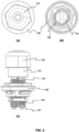
Figure 2 shows (a) a top view; (b) a bottom view; and (c) a side view of the example stopper assembly ofFigure 1 ; -
Figure 3 shows a cross-sectional side view of the example stopper assembly ofFigure 1 ; -
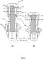
Figure 4 shows cross-sectional side views of the example stopper assembly ofFigure 1 in (a) a first, expanded position; and (b) a second, compressed position; -
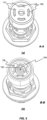
Figure 5 shows a cross-sectional perspective views through (a) section A-A; and (b) section B-B ofFigure 4(b) (compressed); -
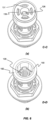
Figure 6 shows a cross-sectional perspective views through (a) section C-C; and (b) section D-D ofFigure 4(a) (expanded); and -
Figure 7 shows a close-up of a vehicle structure with an example stopper assembly operably coupled thereto. - In the drawings, like reference numerals refer to like parts.
- Certain terminology is used in the following description for convenience only and is not limiting. The words 'lower' and 'upper' designate directions in the drawings to which reference is made and are with respect to the described component when assembled and mounted. The words 'inner', 'inward' and 'outer', 'outwardly' refer to directions toward and away from, respectively, a designated centreline or a geometric centre of an element being described (e.g. central axis), the particular meaning being readily apparent from the context of the description.
- Further, as used herein, the terms 'coupled', and 'mounted' are intended to include direct connections between two members without any other members interposed therebetween, as well as, indirect connections between members in which one or more other members are interposed therebetween. The terminology includes the words specifically mentioned above, derivatives thereof, and words of similar import.
- Further, unless otherwise specified, the use of ordinal adjectives, such as, 'first', 'second', 'third' etc. merely indicate that different instances of like objects are being referred to and are not intended to imply that the objects so described must be in a given sequence, either temporally, spatially, in ranking or in any other manner.
- Referring now to
Figures 1 to 3 , there is shown an example embodiment of anadjustable stopper assembly 100 including atubular support member 120 extending between aproximal end portion 124 and adistal end portion 122 along a first central axis 'X'. Thestopper assembly 100 also includes atubular head member 150, having aninner passage 151 extending between aproximal end 154 and adistal end 152 along a second central axis (coaxial with the first central axis 'X', during use, not shown), wherein thehead member 150 is configured to coaxially and telescopingly receive theproximal end portion 124 of thesupport member 120. In the example shown, the first central axis 'X' is coaxial with the second central axis (not shown). That is, thehead member 150 and thesupport member 120 of thestopper assembly 100 have a common central axis 'X', when operably assembled. - Furthermore, the
head member 150 is adapted to move at least axially, in use, relative to thesupport member 120, between a first position and a second position along said first central axis 'X'. - In the example of
Figures 1 to 3 , thehead member 150 is shown in the second position (i.e. in a compressed arrangement), as explained in more detail with reference toFigure 4 . - The
head member 150 includes abump cap 160. Thebump cap 160 is formed of a resilient material. In the example shown, thebump cap 160 is formed of an elastomer (e.g. a foam elastomer or the like), such as, for example, EPDM (Ethylene-Propylene-Diene rubbers) or a thermoplastic elastomer (TPE) (or a combination thereof) at a Shore A hardness scale of 60-70ShA. - The
bump cap 160 is mounted, in this case detachably mounted, to thehead member 150. Thebump cap 160 is mounted over a retaining rib orflange 155, which is configured to retainingly engage acorresponding recess 165 on theinner surface 162 of thebump cap 160. Thus, thebump cap 160 is retained so as to move relative to thesupport member 120 together with thehead member 150. - The
bump cap 160 is arranged to cover anouter surface 157 of thehead member 150 so as to contactingly engage a second component received by thestopper assembly 100, during use. - The
stopper assembly 100 of this particular example further comprises four circumferentially equidistantly spaced resilientlydeformable projections 159, provided between theproximal end portion 124 of thesupport member 120 and theproximal end 154 of thehead member 150 within theinner passage 151. Thedeformable projections 159 are adapted to contactingly engage with thesupport member 120 when thehead member 120 is in the second position, i.e. compressed. - It is understood by the person skilled in the art that any suitable number of resiliently
deformable projections 159 may be used. Here, each resilientlydeformable projection 159 projects away from aninner surface 158 of theproximal end 154 of theinner passage 151. As shown particularly inFigure 3 , in the second position, each resilientlydeformable projection 159 projects towards thedistal end 152 of theinner passage 151 and, at least a portion of theprojections 159, towards the second central axis (not shown, but coaxial with the first central axis when assembled) of thehead member 150. - In the described example embodiment, each resiliently
deformable projection 159 is integrally formed with thebump cap 160 and configured to project away from alower surface 162 of thebump cap 160 through respective apertures orslots 131 of thehead member 150. Each resilientlydeformable projection 159 also projects towards the second central axis and thedistal end 152 of theinner passage 151. In this way, each resilientlydeformable projection 159 extends towards theproximal end portion 124 of thesupport member 120 in the first position. - With additional reference to
Figure 5(a) , each resilientlydeformable projection 159 of the plurality of resilientlydeformable projections 159 is arranged circumferentially about the second central axis (coaxial with the first central axis 'X', during use). The resilientlydeformable projections 159 are evenly spaced about the second central axis. The resilientlydeformable projections 159 project throughslots 131 in theproximal end 154 of thehead member 150. In this way, thebump cap 160 and resilientlydeformable projections 159 are formed as a single, or unitary part integral with thebump cap 160. Thebump cap 160 and resilientlydeformable projections 159 are provided in a common material, in this case a common resilient material. Thestopper assembly 100 is thereby easier to manufacture and to assemble. - The
support member 120 comprises a biasingmember 129 operably provided within aninner passage 125. The biasingmember 129 extends from thedistal end portion 122 of thesupport member 120 within aninner passage 125 of thesupport member 120 towards theproximal end portion 124 and into theinner passage 151 of thehead member 150. In the example shown, the biasingmember 129 is a longitudinal coil spring, but it is understood by the person skilled in the art that any other suitable biasing means may be used. The biasingmember 129 is adapted to bias thehead member 150 towards the first position in use, as described in more detail with respect toFigure 4 . - The example embodiment of the
stopper assembly 100 further includes acoupling member 180, coupleable to a vehicle structure. In the example shown, thecoupling member 180 is adapted to couple to an opening or aperture of the vehicle structure. Thecoupling member 180 includes an annular flange 184 with circumference suitable to provide an interference fit within the opening as is known in the art. - A
first sealing member 191 is provided to seal between the annular flange 184 and the opening or aperture when thecoupling member 180 is coupled to thepanel 199. In this way, with thestopper assembly 100 coupled to the vehicle structure, ingress of moisture through the opening is prevented. - The
distal end portion 122 of thesupport member 120 includes anouter thread portion 128. Thecoupling member 180 has aninner thread portion 182 provided thereon and configured the threadingly engage with theouter thread portion 128 of thetubular support member 120. In this way, when coupled to the vehicle structure, the height of thehead member 150 of thestopper assembly 100 relative to the vehicle structure may be selectively adjusted. That is, the spacing between thehead member 150 and the vehicle structure when thestopper assembly 100 is unloaded may be adjusted by threadingly rotating thesupport member 120 relative to thecoupling member 180. Thus, thestopper assembly 100 is selectively adjustable to provide a predetermined engagement distance between the vehicle structure and a second component moving theretoward. - The
coupling member 180 may include asecond sealing member 192 provided to seal the cooperatinginner thread portion 182 andouter thread portion 128. Thesecond sealing member 192 is a predetermined portion of the outer thread portion and configured to engage with each of theinner thread portion 182 so as to provide a fluid seal between the inner andouter thread stopper assembly 100 coupled to the vehicle structure, ingress of moisture around thethread portions - With additional reference to
Figure 5(b) , theproximal end portion 124 of thesupport member 120 includes a plurality offlange members 126. Eachflange member 126 extends axially with respect to the first central axis so as to extend from theproximal end portion 124 towards thedistal end portion 122 of thesupport member 120. -
Figures 6(a) and (b) show similar cross sectional views of thestopper assembly 100 as inFigures 5(a) and (b) , but in the expanded (second) position. - Each
flange member 126 projects radially outwardly from an outer surface of thesupport member 120. Theflange members 126 are circumferentially spaced on the outer surface. In this way channels 136 are provided betweenadjacent flange members 126 which permit air to flow into or out of theinner passage 151 as thehead member 150 moves axially relative to thesupport member 120. Thus, theinner passage 151 remains in fluid communication with the ambient atmosphere during use of thestopper assembly 100. - The
distal end 152 of thehead member 150 includes an inner rim orflange member 156. Theinner rim member 156 projects radially inward at the distal 152 end towards the second central axis. Theinner rim member 156 extends towards the outer surface of thesupport member 120 on which theflange members 126 are provided. Theinner rim member 156 is configured to cooperatingly engage with theflange members 126 in use. In this way, theinner rim member 156 and theflange members 126 together provide a predetermined limit to the relative axial movement of thehead member 150 away from thedistal end portion 122 of thesupport member 120. In the example shown, the position in which the inner rim orflange member 156 cooperatingly engages theflange members 126 provides the first position of thehead member 150 along the first central axis 'X'. - Referring now to
Figure 4 , there are shown cross-sectional views of thestopper assembly 100 ofFigure 1 in use. As shown inFigure 4(a) , thestopper assembly 100 is in a first, or extended position. As shown inFigure 4(b) , the stopper assembly is in a second, or compressed position. Thehead member 150 of thestopper assembly 100 is adapted to move, in use, relative to saidsupport member 120, along the first central axis 'X' between the first position and the second position, limited by cooperatingflange members - Referring in particular to
Figure 4(a) , thestopper assembly 100 is in a first, or extended position. With thestopper assembly 100 operably coupled to a vehicle structure a second component is disengaged from thestopper assembly 100 and thestopper assembly 100 is unloaded. - The
proximal end portion 124 of thesupport member 120 is received in theinner passage 151 of thehead member 150. Each resilientlydeformable projection 159 is contactingly engaged with theproximal end portion 124 of thesupport member 120. Because thestopper assembly 100 is unloaded, each resilientlydeformable projection 159 is in an extended position. Thus, each resilientlydeformable projection 159 projects away from thelower surface 162 of thebump cap 160, and projects towards thedistal end 152 of theinner passage 151. - In the extended position, the resiliently
deformable projections 159 engage theproximal end portion 124 of thesupport member 120. This provides a further bias of thehead member 150 away from thesupport member 120. Thehead member 150 is thereby biased away from thesupport member 120 so that theflange members 126 are engaged with theinner rim member 156. - The biasing
member 129 is disengaged from thehead member 120 in the first position. However, the extended resilientlydeformable projections 159 take up the additional axial displacement between thehead member 150 and thesupport member 120 provided by the relative positions of theflange members 126 and theinner rim member 156. Accordingly, the resilientlydeformable projections 159 eliminate unwanted rattling by ensuring there is no free movement between thehead member 150 and thesupport member 120 when thestopper assembly 100 is unloaded. - In the first position, the
stopper assembly 100 is disposed to engage a second component. Referring additionally toFigure 7 , thestopper assembly 100 is coupled to a vehicle structure (e.g. trunk door) 199 so that thebump cap 160 is oriented to engage a component 200 (e.g. vehicle chassis, only partly shown for reference) moving towards thestopper assembly 100. Thus, when thestopper assembly 100 is coupled to a moving component (trunk door) of thevehicle structure 199, thestopper assembly 100 is disposed to engage a fixed component, for example a chassis to which the vehicle structure is attached. In an alternative arrangement, the stopper assembly may be coupled to the fixed component of a vehicle structure. The stopper assembly is thus oriented to engage the moving component that moves towards the fixed component. - Regardless of the arrangement, an engagement between the
stopper assembly 100 and a second component causes thestopper assembly 100 to be compressed. The initial impact of the engagement provides a loading force. The loading force overcomes the bias provided by the resilientlydeformable projections 159 so that thehead member 150 moves along the coaxial first and second central axes towards thedistal end portion 122 of thesupport member 120. Each resilientlydeformable projection 159 contactingly engages theproximal end portion 124 of thesupport member 120 as thehead member 150 moves towards the second position. Thus, as thehead member 150 moves along the first central axis 'X' towards the second position, each resilientlydeformable projection 159 is resiliently deflected. - In this way, deflection of the resiliently
deformable projections 159 provides a cushioning effect of the initial impact of the engagement of thesecond component 120 with thestopper assembly 100. The resilientlydeformable projections 159 are adapted to provide a predetermined deflection in response to the loading force. That is, the angle, dimensions and material of the resilientlydeformable projections 159 may be modified to provide a desired deflection depending on the components with which thestopper assembly 100 is used. Thestopper assembly 100 thus dampens the engagement with the second component, reducing impact vibrations and noise generated by the impact. - Subsequently, the resiliently
deformable projections 159 deflect sufficiently so that theproximal end 154 of thehead portion 150 engages the biasingmember 129. Thereafter, the biasingmember 129 is also deflected by the loading force, providing a further cushioning effect. The second component is thereby brought to rest with thestopper assembly 100 in the compressed position, as shown inFigure 4(b) . - Various example embodiment and configurations of the
stopper assembly 100 are possible without diverting from the scope of the present invention. The described example relates to astopper assembly 100 integrally formed with thebump cap 160. However, in an alternative example embodiment, at least one resiliently deformable projection may be formed on the inner surface of theinner passage 151 of thehead portion 150. In this way, each resiliently deformable projection may be formed in a material common to the walls of the inner passage of the head portion. Alternatively, each resilientlydeformable projection 159 may be formed in a different material to the walls of the inner passage, for example by co-moulding the resiliently deformable projections onto the head portion 150 (e.g. a 2k material). - In a further alternative embodiment, at least one resiliently deformable projection may be formed on the proximal end portion of the
support member 120. Each resiliently deformable projection is thus adapted to contactingly engage thehead member 150 in the second position. That is, in the first position, each resiliently deformable projection is in an extended position. Each resiliently deformable projection projects away from the proximal end portion of thesupport member 120, and projects towards the proximal end of theinner passage 151 of thehead member 150. - The engagement of a second component proceeds substantially as described with reference to
Figure 4 , except that as thehead member 150 moves along the first central axis towards the distal end portion of thesupport member 120, the resilientlydeformable projections 159 contactingly engage with an inner surface of the proximal end of thehead portion 150. Consequently, a similar cushioning effect to a loading force of engagement ofstopper assembly 100 with a second component is provided. Subsequent movement of thehead member 150 along the first central axis deflects each resilientlydeformable projection 159 towards the first central axis. Each resilientlydeformable projection 159 is deflected by the proximal end of thehead member 150. - Any of the more rigid components, such as, the
support member 120, thetubular head member 150 and thecoupling member 180 may be made from a hard material, such as, for example, glass fibre reinforced Polypropylene (PP) (e.g. 30Gf, 30%), glass fibre reinforced 6-6-Nylon (i.e.PA66 + 30Gf), Polyoxymethylene (POM) or Polyphenylene-ether (PPE). - Throughout the description and claims of this specification, the words "comprise" and "contain" and variations of them mean "including but not limited to", and they are not intended to (and do not) exclude other moieties, additives, components, integers or steps. Throughout the description and claims of this specification, the singular encompasses the plural unless the context otherwise requires. In particular, where the indefinite article is used, the specification is to be understood as contemplating plurality as well as singularity, unless the context requires otherwise.
- Features, integers, characteristics or groups described in conjunction with a particular aspect, embodiment or example of the invention are to be understood to be applicable to any other aspect, embodiment or example described herein unless incompatible therewith. All of the features disclosed in this specification (including any accompanying claims, abstract and drawings), and/or all of the steps of any method or process so disclosed, may be combined in any combination, except combinations where at least some of such features and/or steps are mutually exclusive. The invention is not restricted to the details of any foregoing embodiments. The invention extends to any novel one, or any novel combination, of the features disclosed in this specification (including any accompanying claims, abstract and drawings), or to any novel one, or any novel combination, of the steps of any method or process so disclosed.
- The reader's attention is directed to all papers and documents which are filed concurrently with or previous to this specification in connection with this application and which are open to public inspection with this specification, and the contents of all such papers and documents are incorporated herein by reference.
-
- 100
- Adjustable stopper assembly
- 120
- Tubular support member
- 122
- Distal end portion
- 124
- Proximal end portion
- 125
- Inner passage of support member
- 126
- Flange member(s)
- 128
- Outer thread portion
- 129
- Biasing member (coil spring)
- 131
- slots
- 136
- channels
- 150
- Tubular head member
- 151
- Inner passage of head member
- 152
- Distal end
- 154
- Proximal end
- 155
- Retaining rib/flange
- 156
- Inner rim / flange member
- 157
- Outer surface
- 158
- Inner surface of proximal end
- 159
- Resiliently deformable projections
- 160
- Bump cap
- 162
- Inner surface of bump cap
- 165
- recess
- 180
- Coupling member
- 182
- Inner thread portion
- 184
- Annular flange
- 191
- First sealing member
- 192
- Second sealing member
- 199
- Vehicle structure / moveable trunk door
- 200
- Vehicle structure / component / chassis
Claims (11)
- An adjustable stopper assembly comprising:a tubular support member extending between a proximal end portion and a distal end portion along a first central axis; anda tubular head member, comprising an inner passage extending between a proximal end and a distal end along second central axis, wherein said head member is configured to coaxially telescopingly receive said proximal end portion of said support member, and is adapted to move, in use, relative to said support member, between a first position and a second position along said first central axis;wherein said assembly further comprises at least one resiliently deformable projection, provided between said proximal end portion of said support member and said proximal end of said inner passage of said head member, and which is adapted to contactingly engage with one of said support member and said head member when said head member is in said second position.
- An adjustable stopper assembly according to claim 1, wherein said proximal end of said inner passage of said head member comprises said at least one resiliently deformable projection, and wherein said at least one resiliently deformable projection is adapted to contactingly engage with said proximal end portion of said support member when said head portion is in said second position.
- An adjustable stopper assembly according to claim 2, wherein, when in said second position, said at least one resiliently deformable projection projects away from an inner surface of said proximal end of said inner passage and towards said distal end and said second central axis of said inner passage.
- An adjustable stopper assembly according to any one of claims 2 and 3, wherein said head member comprises a bump member formed of a resilient material.
- An adjustable stopper assembly according to claim 4, wherein said at least one resiliently deformable projection is integrally formed with said bump member.
- An adjustable stopper assembly according to any one of the preceding claims, wherein said at least one resiliently deformable projection comprises a plurality of projections arranged circumferentially about said second central axis, during use.
- An adjustable stopper assembly according to any one of the preceding claims, wherein said proximal end portion of said support member comprises at least one first flange member projecting radially outwards way from said first central axis.
- An adjustable stopper assembly according to claim 7, wherein said distal end of said head member comprises at least one second flange member projecting radially inwards towards said first central axis, wherein said at least one second flange member is configured to cooperatingly engage with said at least one first flange member, during use.
- An adjustable stopper assembly according to any one of the preceding claims, wherein said support member comprises a biasing member adapted to bias said head member towards said first position, during use.
- An adjustable stopper assembly according to any one of the preceding claims, wherein said assembly further comprises a coupling member, coupleable to a vehicle structure and adapted to operably couplingly receive said distal end portion of said support member.
- An adjustable stopper assembly according to claim 10, wherein said distal end portion of said support member comprises an outer thread portion and said coupling member comprises an inner thread portion configured to threadingly engage with said outer thread portion.
Applications Claiming Priority (1)
| Application Number | Priority Date | Filing Date | Title |
|---|---|---|---|
| EP22382455 | 2022-05-11 |
Publications (1)
| Publication Number | Publication Date |
|---|---|
| EP4276266A1 true EP4276266A1 (en) | 2023-11-15 |
Family
ID=81648057
Family Applications (1)
| Application Number | Title | Priority Date | Filing Date |
|---|---|---|---|
| EP23169072.8A Pending EP4276266A1 (en) | 2022-05-11 | 2023-04-20 | Stopper assembly |
Country Status (1)
| Country | Link |
|---|---|
| EP (1) | EP4276266A1 (en) |
Citations (3)
| Publication number | Priority date | Publication date | Assignee | Title |
|---|---|---|---|---|
| EP1659249A1 (en) * | 2004-11-18 | 2006-05-24 | EJOT GmbH & Co. KG | Elastic stop buffer, in particular for closure lids |
| DE102011101393A1 (en) * | 2011-05-13 | 2012-11-15 | Audi Ag | Compression buffer arrangement for supporting cap or flap like body attachment part at body frame of kit, has base body, which is fastened at body attachment part and adjusting pin which is held in axially adjustable manner on base body |
| KR20190007545A (en) * | 2017-07-12 | 2019-01-23 | 현대자동차주식회사 | Over slam bumper apparatus for tail gate pop-up |
-
2023
- 2023-04-20 EP EP23169072.8A patent/EP4276266A1/en active Pending
Patent Citations (3)
| Publication number | Priority date | Publication date | Assignee | Title |
|---|---|---|---|---|
| EP1659249A1 (en) * | 2004-11-18 | 2006-05-24 | EJOT GmbH & Co. KG | Elastic stop buffer, in particular for closure lids |
| DE102011101393A1 (en) * | 2011-05-13 | 2012-11-15 | Audi Ag | Compression buffer arrangement for supporting cap or flap like body attachment part at body frame of kit, has base body, which is fastened at body attachment part and adjusting pin which is held in axially adjustable manner on base body |
| KR20190007545A (en) * | 2017-07-12 | 2019-01-23 | 현대자동차주식회사 | Over slam bumper apparatus for tail gate pop-up |
Similar Documents
| Publication | Publication Date | Title |
|---|---|---|
| US8291547B2 (en) | Cushion clip | |
| US20170234434A1 (en) | Dust seal | |
| US8984715B2 (en) | Cushion clip | |
| US20140150207A1 (en) | Vehicle opening/closing member damper apparatus and vehicle opening/closing member stopper apparatus | |
| US7416174B2 (en) | Mount assembly | |
| US10451131B2 (en) | Shock-absorbing device | |
| US20050017421A1 (en) | Two stage isolation mount assembly | |
| JP2014185657A (en) | Dust cover assembly | |
| US11511695B2 (en) | Steering wheel with airbag apparatus and damper apparatus | |
| US20060234619A1 (en) | Intake duct for vehicle | |
| US12240365B2 (en) | Sleeve device for a headrest | |
| US20230174153A1 (en) | A vibration damper assembly, a method of tuning such an assembly, and a method for manufacturing vibration damper assemblies | |
| KR102070640B1 (en) | Over-slam bumper with fixation and buffer | |
| CN110831821A (en) | Damping ring and airbag module having such a damping ring | |
| US20050236749A1 (en) | Cover assembly for a pneumatic spring | |
| CN120303496A (en) | Cab suspension parts | |
| US20240301937A1 (en) | Damper | |
| US12123250B2 (en) | Fasteners | |
| JP2008094261A (en) | Cushion clip | |
| JPH11170836A (en) | Strut mount | |
| JP7115967B2 (en) | cushion device | |
| JP6339614B2 (en) | Bound stopper | |
| JP2008534892A (en) | Air bag inflator vibration damper | |
| US11766989B1 (en) | Collapsible hood bumper bracket | |
| US20240190225A1 (en) | Inner belt mounting structure of door for vehicle |
Legal Events
| Date | Code | Title | Description |
|---|---|---|---|
| PUAI | Public reference made under article 153(3) epc to a published international application that has entered the european phase |
Free format text: ORIGINAL CODE: 0009012 |
|
| STAA | Information on the status of an ep patent application or granted ep patent |
Free format text: STATUS: THE APPLICATION HAS BEEN PUBLISHED |
|
| AK | Designated contracting states |
Kind code of ref document: A1 Designated state(s): AL AT BE BG CH CY CZ DE DK EE ES FI FR GB GR HR HU IE IS IT LI LT LU LV MC ME MK MT NL NO PL PT RO RS SE SI SK SM TR |
|
| STAA | Information on the status of an ep patent application or granted ep patent |
Free format text: STATUS: REQUEST FOR EXAMINATION WAS MADE |
|
| 17P | Request for examination filed |
Effective date: 20240510 |
|
| RBV | Designated contracting states (corrected) |
Designated state(s): AL AT BE BG CH CY CZ DE DK EE ES FI FR GB GR HR HU IE IS IT LI LT LU LV MC ME MK MT NL NO PL PT RO RS SE SI SK SM TR |
|
| STAA | Information on the status of an ep patent application or granted ep patent |
Free format text: STATUS: EXAMINATION IS IN PROGRESS |
|
| 17Q | First examination report despatched |
Effective date: 20250318 |