EP4276257A1 - A connecting device for shutter slats and a shutter system comprising two such connecting devices - Google Patents
A connecting device for shutter slats and a shutter system comprising two such connecting devices Download PDFInfo
- Publication number
- EP4276257A1 EP4276257A1 EP23020214.5A EP23020214A EP4276257A1 EP 4276257 A1 EP4276257 A1 EP 4276257A1 EP 23020214 A EP23020214 A EP 23020214A EP 4276257 A1 EP4276257 A1 EP 4276257A1
- Authority
- EP
- European Patent Office
- Prior art keywords
- socket
- axis
- lateral profile
- wall
- slat holder
- Prior art date
- Legal status (The legal status is an assumption and is not a legal conclusion. Google has not performed a legal analysis and makes no representation as to the accuracy of the status listed.)
- Withdrawn
Links
Images






Classifications
-
- E—FIXED CONSTRUCTIONS
- E06—DOORS, WINDOWS, SHUTTERS, OR ROLLER BLINDS IN GENERAL; LADDERS
- E06B—FIXED OR MOVABLE CLOSURES FOR OPENINGS IN BUILDINGS, VEHICLES, FENCES OR LIKE ENCLOSURES IN GENERAL, e.g. DOORS, WINDOWS, BLINDS, GATES
- E06B7/00—Special arrangements or measures in connection with doors or windows
- E06B7/02—Special arrangements or measures in connection with doors or windows for providing ventilation, e.g. through double windows; Arrangement of ventilation roses
- E06B7/08—Louvre doors, windows or grilles
- E06B7/084—Louvre doors, windows or grilles with rotatable lamellae
- E06B7/086—Louvre doors, windows or grilles with rotatable lamellae interconnected for concurrent movement
-
- E—FIXED CONSTRUCTIONS
- E04—BUILDING
- E04F—FINISHING WORK ON BUILDINGS, e.g. STAIRS, FLOORS
- E04F10/00—Sunshades, e.g. Florentine blinds or jalousies; Outside screens; Awnings or baldachins
- E04F10/08—Sunshades, e.g. Florentine blinds or jalousies; Outside screens; Awnings or baldachins of a plurality of similar rigid parts, e.g. slabs, lamellae
- E04F10/10—Sunshades, e.g. Florentine blinds or jalousies; Outside screens; Awnings or baldachins of a plurality of similar rigid parts, e.g. slabs, lamellae collapsible or extensible; metallic Florentine blinds; awnings with movable parts such as louvres
Definitions
- the invention concerns a connecting device for shutter slats and a shutter system comprising two such connecting devices, the system being designed in particular for use in garden pergolas, gazebos, terraces etc., not excluding its use as a window shutter.
- Various types of shutter systems are known in which the slats are orientable between open and closed positions. Many such systems have the disadvantage that their slats are mounted in side rails even before the rails are attached to a support or window frame. In consequence, a complete system must be mounted as a large element which makes the installation difficult and requires a lot of effort and precision.
- a shutter system in which the slats may be installed in an already mounted framework was described e.g. in a French patent FR2986819 .
- This patent discloses a system comprising a device for connection between a blade and a framework mounted in an opening, the framework being designed for installation of orientable slats able to pivot around mutually parallel axes between an open position and a closed position.
- the system comprises at least one operating rod for changing the position of the blades and a suitable number of pairs of connecting pieces to be positioned on the ends of said blades.
- the blades are inserted into the connecting pieces that are provided with first and second connecting means for pivotable engagement of said connecting pieces with the framework on one side and with the operating rod on the other side. Both the first and the second connecting means are latch-coupled with the complementary connecting means carried by the operating rod and the framework.
- FR2986819 has a disadvantage consisting in that the blades are inserted at the end of the installation which imposes a specific cross-section of the blades to be insertable into the connecting pieces.
- the use of more rounded cross-sections of the blades is problematic. Additionally, it results in a potential risk the blades falling out in consequence of a slight bump (e.g. by a ball).
- the aim of the invention was to provide a connecting device for shutter slats and a shutter system the installation of which would not be cumbersome and tools-free and in which replacement of the slats would be easy.
- the aim of the invention was to provide a system in which the slats would be attached in a most reliable way and would not fall-out during normal use.
- a connecting device for shutter slats comprising a fixed lateral profile having a longitudinal axis and a spacing rod having a longitudinal axis parallel to the axis of the lateral profile, the device further comprising at least one slat holder connectable to the shutter slat, the slat holder having a front wall facing the lateral profile, on which front wall a longitudinal axis of the slat holder lies, each slat holder being releasably engageable with the lateral profile by means of a first connecting assembly, and each slat holder being releasably engageable with the spacing rod by means of a second connecting assembly, so that each slat holder is rotatable in relation to the lateral profile and to the spacing rod.
- the device according to the invention is characterized in that the first connecting assembly may be in a partly engaged state and in a completely engaged state, the first connecting assembly being in the partly engaged state when the slat holder is engaged with the lateral profile and the second connecting assembly is not engaged, and in said partly engaged state there is only one position of the slat holder in relation to the lateral profile in which the first connecting assembly may be disengaged, said only one position being such that the angle between the axis of the slat holder and the axis of the lateral profile equals a defined installation angle, while upon engagement of the second connecting assembly, the first connecting assembly is in the completely engaged state and the angle between the axis of the slat holder and the axis of the lateral profile is larger than said defined installation angle.
- the first connecting assembly comprises a rigid pin protruding from the front wall of the slat holder and a socket located on the lateral profile, the rigid pin having a first axis perpendicular to the axis of the lateral profile
- the second connecting assembly comprises an elastic pin protruding from the front wall of the slat holder and an opening located on the spacing rod, the elastic pin having a second axis perpendicular to the axis of the spacing rod, the first axis and the second axis intersecting said front wall at points laying on the axis of the slat holder.
- the lateral profile has a first wall facing the front wall of the slat holder and a second wall perpendicular to said first wall
- the rigid pin comprises an internal part and an external part that are connected by a rail-shaped narrowing having a form of a section of a cylinder having said second axis
- the socket having an external part with an entry hole located on the second wall of the lateral profile, the entry hole being shaped to enable introduction of the rigid pin into the socket
- said external part of the socket comprising a guide having a curved shape adapted to receive said rail during the introduction of the rigid pin into the socket through the entry hole
- the socket having an internal part with an operational hole located on said first wall of the lateral profile, wherein upon the engagement of the first connecting assembly, the rigid pin is located in said internal part of the socket and it connects pivotally with said internal part through said operational hole.
- the lateral profile has a third wall opposite to its second wall, the third wall having a wavy shape, and the spacing rod wall facing the lateral profile has a wavy shape matching the shape of said third wall of the lateral profile.
- said guide is formed by a space located between a first projection protruding inwardly from the external part of the socket and an opposite second projection, the guide with the first and second projection divide the external part of the socket into an internal passage located away from the first wall of the lateral profile and an external passage located close to the first wall of the lateral profile.
- the internal part of the rigid pin is located in said internal passage and the external part of the rigid pin is located in said external passage.
- the internal part of the socket is formed by a fragment of a cylindrical wall of the socket having a first socket diameter defining the operational hole, and a fragment of a cylindrical wall of the socket having a second socket diameter, the second socket diameter being larger than the first socket diameter, wherein the external part of the rigid pin has a shape of a cylinder having a first pin diameter, while its internal part has a shape of a cylinder having a second pin diameter, the second pin diameter being larger than the first pin diameter.
- the internal part of the socket has a shape of a truncated cone having a first small socket diameter defining the operational hole and a second large socket diameter
- the external part of the rigid pin has a shape of a truncated cone having a first small pin diameter
- its internal part has a shape of a truncated cone having a second large pin diameter
- the second large pin diameter is larger than the first small pin diameter
- the lateral profile may be composed of individual sections mutually connectable by projections and corresponding recesses located at their respective ends.
- the spacer rod may also be composed of individual sections mutually connectable by form-fitting snap connectors located at their respective ends.
- shutter system comprising at least one horizontal pivotable shutter slat having a longitudinal axis, characterized in that it further comprises two connecting devices according to the invention, said two connecting devices being their mutual mirror reflections and each shutter slat is fitted by its one end to one of said connecting devices and by its other end to the other of said two connecting devices, each slat holder having a cavity the shape of which corresponds to the shutter slat cross-section.
- the shutter system comprises five shutter slats 1 and two connecting devices U, U", each comprising respectively a lateral profile 2, 2', a spacing rod 3, 3' and five slat holders 4, 4' connecting the shutter slats 1 with the lateral profiles 2, 2' and the spacing rods 3, 3'. Any number of the shutter slats 1 and the respective slat holders 4, 4' may be foreseen.
- the shutter slats 1 having longitudinal axes X are mounted horizontally and they are pivotable between a closed position and an open position, while the lateral profiles 2, 2' that are perpendicular to the shutter slats 1, have longitudinal axes Y2, Y2' and they may be fixed to any type of suitable supports (not shown in the drawing).
- the spacing rods 3, 3' have longitudinal axes Y3, Y3'. Once installed, they are vertically movable up and down and simultaneously displaced towards and away in relation to the lateral profiles 2, 2'. Both the lateral profiles 2, 2' and the spacing rods 3, 3' are pivotally connected to the shutter slats 1 by means of the slat holders 4, 4'. This way of connecting the system components provides a shutter system all the horizontal slats 1 of which may be simultaneously pivoted by means of the spacing rods 3, 3' in order to close or open the whole shutter.
- the components of the connecting device of the invention will be described that are located on one side of the shutter system of the invention, specifically on the right side in fig. 1a , the components including the lateral profile 2, the spacing rod 3 and the slat holder 4.
- the respective components 2', 3', 4' are located, the components 2' and 4' being mirror reflections of the components 2 and 4 respectively, while the spacing rods 3' are in the described embodiment identical to the spacing rods 3.
- the numbers marked with ', indicated in parentheses in the figures refer to their counterparts on the other side of the system.
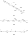
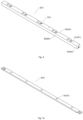
- a segment of the lateral profile 2 is shown in various views and cross-sections, said segment being composed here of mutually connected sections, the num ber of which defines the length of the profile (the height of the shutter).
- the lateral profiles may also be realized as single components.
- the individual sections of the lateral profile 2 may be connected by means of typical formations like recesses and corresponding projections shown e.g. in fig. 2d .
- Figs. 2a and 2b show a segment of an exemplary lateral profile 2 comprising sockets 7 the number of which should correspond to the number of the shutter slats 1.
- Each socket 7 constitutes one of the two components of a first connecting assembly 5 to be described in detail in the following text and shown in a perspective view in fig. 8 .
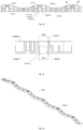
- a segment of the spacing rod 3 is shown in various views, said segment - similarly to the lateral profile 2 - being composed here of snap-connected sections, the number of which defines the length of the rod (the height of the shutter).
- the spacing rods may also be realized as single components.
- the spacing rod 3 has a generally wavy shape having a longitudinal axis Y3 with two substantially flat wide sides and two narrow sides.
- the spacing rod 3 may also be a straight rod or it may have a wavy shape on one side, similarly to the lateral profile 2.
- Exemplary optional shapes of the spacing rod 3 are shown in figs. 7a and 7b .
- the individual sections of the spacing rod 3 are connected by means of typical form-fitting snap connectors located at their ends, as shown in figs. 3a-3d , the sections forming upon engagement a stiff connection able to transfer the forces generated during opening and closing of the shutter.
- the spacing rod 3 comprises numerous openings 10 the number of which corresponds to the number of shutter slats 1. Each opening 10 constitutes one of the two components of a second connecting assembly 8 to be described in detail in the following text and shown in a perspective view in fig. 9 .
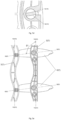
- the slat holder is shown in figs.4a , 4b and 4c . It is a generally oblong spatial profile having a shape adapted to the shape of the cross-section of the shutter slats 1.
- the cross-section of the shutter slats 1 has a shape similar to an ellipse and the slat holder 4 is shaped accordingly.
- the mutually corresponding shapes of the shutter slat cross-section and the slat holder cross-section may be different, e.g. rectangular, wavy, curved, rectangular with a fold.
- the slat holder 4 On one side, the slat holder 4 has an open cavity W in which one end of the shutter slat 1 is received. On the other side, the slat holder 4 has a front wall P on which the elements designed for connecting the slat holder 4 with the lateral profile 2 and the spacing rod 3 are provided. These elements comprise: a rigid pin 6 having a first axis X1 constituting a second component of the first connecting assembly 5, and an elastic pin 9 having a second axis X2 constituting a second component of the second connecting assembly 8, the elastic pin 9 being spaced from the rigid pin 6.
- the intersection points of the first axis X1 of the rigid pin 6 and the second axis X2 of the elastic pin 9 with the front wall P define and axis O of the slat holder, lying on the front wall P and running substantially along this wall.
- the rigid pin 6 is located in the center of the front wall P and the elastic pin 9 is located at its end, however a specialist will appreciate that these are not the only possible locations of the pins 6 and 9.
- the side walls W1, W2 have indentations enabling proper closure of the shutter slats 1, which will be explained in the following.
- the first connecting assembly 5 shown e.g. in fig. 8 comprises the rigid pin 6 located on the slat holder 4 and the socket 7 located on the lateral profile 2.
- the first connecting assembly 5 is designed in such a way that its engagement is realized by introduction of the rigid pin 6 into the socket 7 in only one precisely defined position of the slat holder 4 in relation to the lateral profile 2. Similarly, the disengagement of the first connecting assembly 5 is only possible in the same above described defined position.
- the disengagement of the first connecting assembly 5 is impossible because the slat holder 4 may not be positioned in said defined position in relation to the lateral profile 2. This specific feature of the system according to the invention has been achieved due to a special structure of the rigid pin 6, the socket 7 and the slat holder 4, which will be described below.
- the lateral profile 2 has a first wall S1 facing the front wall P of the slat holder 4 in the installed system, a second wall S2 that is perpendicular to the first wall S1, a third wall S3 opposite to the second wall S2 and a fourth wall S4, shown in figs. 2c and 2e , facing the support of the lateral profile 2.
- the third wall S3 has a wavy shape designed to comply with the wavy shape of the spacing rod 3; however if the spacing rod 3 is straight then the third wall S3 is also straight.
- An optional shape of the lateral profile 2 is shown in fig. 6 .
- the shapes of the third wall S3, the first wall S1 or the second wall S3 of the lateral profile 2 and the spacing rod 3 may be freely chosen. As shown in the figures, they may be e.g. wavy or straight, depending on esthetic requirements.
- each socket 7 located in the lateral profile 2 has an external part 7a with an entrance opening 11 on the second wall S2 side.
- the rigid pin 6 is introduced into the socket 7 through the entrance opening 11.
- the socket 7 has also an internal part 7b with an operational hole 12 on the first wall S1.
- the rigid pin 6, which is connected with the front wall P, passes through the operational hole 12 upon engagement of the first connecting assembly 5.
- the socket 7 comprises a guide 13 in its external part 7a and the rigid pin 6 has a rail-shaped narrowing 14 (shown in fig. 4a ).
- the guide 13 is formed by a hollow space between a first protrusion 15a and a second protrusion 15b, both protrusions extending inwardly in the external part 7a of the socket 7.
- the protrusions 15a and 15b divide the external part 7a of the socket 7 into an internal passage 17 and an external passage 18, as shown in figs. 2c and 2e .
- the internal part 7b of the socket 7 remains undivided.
- the first projection 15a has a wall 16a facing the guide 13, the wall 16a being flat and perpendicular to the axis Y2, while the second projection 15b has wall 16b facing the guide 13, the wall 16a being curved in such a way that the guide 13 diverges towards the entrance opening 11.
- Fig. 2e shows the cross-section B-B indicated in fig. 2b and running through the undivided internal part 7b of the socket 7, the internal part 7b being formed by a first partly cylindrical wall having a first socket diameter D1 and a second partly cylindrical wall having a second socket diameter D2.
- the first partly cylindrical wall defines the operational hole 12 and it evolves into the divergent walls of the external passage 18.
- the second partly cylindrical wall evolves into the divergent walls of the internal passage 17.
- the second socket diameter D2 is larger than the first socket diameter D1.
- the rigid pin 6 has an internal part 19 (on the side of its free end) and an external part 20 (on the side of the front wall P), between which the rail-type narrowing 14 is located.
- both the internal part 19 and the external part 20 have cylindrical shapes, while the rail-type narrowing 14 constitutes a section of a cylinder having an axis coinciding with the second axis X2 of the elastic pin 9.
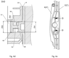
- Figs. 4d and 4e show respectively the cross-section D-D indicated in fig. 4e and a view of the lateral profile 2 connected with the slat holder 4.
- the external part 20 has a first pin diameter d1 and the internal part 19 has a second pin diameter d2.
- the first pin diameter d1 is smaller than the first socket diameter D1
- the second pin diameter d2 is smaller than the second socket diameter D2, the thickness of the rail 14 being smaller than the smallest wideness of the guide 13.
- the rigid pin 6 may be introduced into the internal part 7b of the socket 7 by a sliding-rotational movement around the second axis X2, i.e.
- the rigid pin 6 may not be removed from the internal part 7b of the socket 7 by axial movement but it may be rotated within said internal part 7b because - as mentioned above - the second pin diameter d2 is smaller than the second socket diameter D2 and the first pin diameter d1 is smaller than the first socket diameter D1.
- the same effect may be obtained by designing the rigid pin 6 and the internal part 7b of the socket 7 as in the alternative embodiment represented in figs. 10a and 10b .
- the internal part 7b of the socket 7 has a shape of a truncated cone with its lateral surface extending between the first socket diameter D1 and the second socket diameter D2.
- the external part 20 and the internal part 19 of the rigid pin 6 have also lateral walls formed by rotational surfaces of two respective truncated cones, so that the second pin diameter d2 constitutes the largest diameter of the internal part 19 that is larger than the first pin diameter d1, which in turn is the smallest diameter of the external part 20.
- the external part 20 of the rigid pin 6 has a shape of a truncated cone with a smaller diameter d1 and a larger diameter d1'
- the internal part 19 of the rigid pin 6 has a shape of a truncated cone with a larger diameter d2 and a smaller diameter d2', wherein D2>d2>D1 and d2'>d1'. Consequently, the rigid pin fits within the entrance opening 11 and may not be removed through the operational hole 12.
- Fig. 5a shows that the above mentioned entrance position of the rigid pin 6 in relation to the socket 7 is the position in which the curvature of the rail 14 coincides with the guide 13. In this position, the angle between the axis O and the axis Y2 equals an angle ⁇ 1 the size of which results from the sizes of the interrelated components.
- the slat holder 4 In order for the first connecting assembly 5 to be in a partly engaged state, i.e. in order to introduce the rigid pin 6 into the internal part 7b of the socket 7 through the entrance opening 11, the slat holder 4 must be rotated in relation to the lateral profile 2 so that the angle between the axis O and the axis Y2 is decreased.
- the first connecting assembly 5b shows a situation in which the first connecting assembly 5 is in the partly engaged state, i.e. the rigid pin 6 has been introduced into the internal part 7b of the socket 7 and the second connecting assembly 8 has not yet been engaged. This is a situation when the rigid pin 6 may still be removed from the socket 7 by rotating it back to the angle ⁇ 1 position.
- the angle between the axis O and the axis Y2 equals a defined installation angle ⁇ which is different from the angle ⁇ 1.
- the installation angle ⁇ is smaller than the angle ⁇ 1.
- the slat holder 4 may be turned around the rigid pin 6 located in the internal part 7b which is not divided by the projections 15a, 15b.
- Fig. 5c shows a situation upon engagement of the second connecting assembly 8, when the first connecting assembly 5 is in the completely engaged state and the rigid pin 6 may still be rotated around the first axis X1 within the internal part 7b of the socket 7 but in a limited scope. This is because the angle ⁇ between the axis O and the axis Y2 may not be reduced to equal the installation angle ⁇ due to the presence of the spacing rod 3 engaged with the slat holder 4 by means of the second connecting assembly 8.
- Fig. 5c shows a situation upon engagement of the second connecting assembly 8 when the shutter slats 1 are in their closed position.
- the elastic pin 9 has been snapped into the opening 10 of the spacing rod 3 which required the rotation of the slat holder 4 in relation to the lateral profile 2 around the first axis X1 of the rigid pin 6 located within the internal part 7b.
- This rotation made the removal of the rigid pin 6 through the guide 13 and the entrance opening 11 impossible.
- the angle ⁇ between the axis O and the axis Y2 is larger than the installation angle ⁇ , and the curvature of the rail 14 does not coincide with the guide 13.
- Fig. 5d shows the detail F indicated in fig. 5c , enlarged.
- the components of the first connecting assembly 5 and the second connecting assembly 8 are designed in such a way that when both assemblies are engaged, the system remains in a position that has been imparted thereto due to the frictional forces acting between the respective elements of the connecting assemblies.
- Fig. 5e also shows a situation when the first connecting assembly 5 is in its completely engaged state, i.e. when the second connecting assembly 8 is engaged, but the shutter slats 1 are in their open position. In this position the slat holder 4 has been rotated around the rigid pin 6 located within the internal part 7b; in this situation, the removal of the rigid pin 6 through the guide 13 and the entrance opening 11 is also impossible because the angle ⁇ 1 between the axis O and the axis Y2 is larger than the installation angle ⁇ .
- Fig. 9 shows a perspective view of the second connecting assembly 8 when disengaged; it comprises the elastic pin 9 located on the slat holder 4 and the opening 10 located on the spacing rod 3.
- the elastic pin 9 has a structure enabling snap-coupling with the opening 10 in which the elastic pin 9 remains rotatable.
- the elastic pin 9 is composed of two spaced apart elastic formations, half-circular in cross-section and having thickened endings. Their elasticity enables snap-coupling in the circular openings 10. The coupling is detachable.
- the individual sections of the lateral profiles 2, 2' are connected with each other and mounted to fixed supports so that the fourth walls S4 adjoin the supports and the third walls S3 are in front, i.e. facing the operator.
- the slat holders 4 are fitted on each shutter slat 1 symmetrically on both ends, so that the rigid pins 6, 6' and the elastic pins 9, 9' are respectively coaxial.
- the shutter slats 1 may be connected on both sides with the sockets 7, 7' of the already fixed lateral profiles 2, 2'.
- each shutter slat 1 should be oriented so that the elastic pins 9, 9' are above the rigid pins 6, 6' and in front, i.e. facing the third wall S3 of the lateral profile 2, 2'.
- the rigid pins 6, 6' may then be introduced into the sockets 7, 7' by first turning the slat holders 4, 4' in relation to the lateral profile 2, 2' in order to find such an angular position of the axis O, O' of the slat holders 4, 4' in relation to the axes Y2, Y2' in which the rail 14, 14' coincides with the guide 13, 13'.
- each slat holder 4, 4' should be rotated in relation to the lateral profile 2, 2' around the axis X1, X1' of the rigid pin 6, 6' and then the elastic pins 9, 9' may be introduced into their sockets, i.e. the openings 10, 10'.
- the spacing rods 3, 3' should be fixed in such a way that in the closed position of the system their wavy walls adjoin the wavy third walls S3 of the lateral profiles 2, 2' and the neighboring slat holders 4, 4' overlap each other by their indentations in the side walls shown in fig. 4a .
- the individual sections of the spacing rods 3, 3' may be connected to each other.
- a specific advantage of the invention is that the lateral profiles 2, 2' may be first separately fixed to their supports and then the long shutter slats 1 may be fixed one by one which makes the system easy to be installed by one person.
- the lateral slats 2, 2', the spacing rods 3, 3' and the slat holders 4, 4' may be made e.g. of metal, plastic or wood, or any other suitable material.
Landscapes
- Engineering & Computer Science (AREA)
- Civil Engineering (AREA)
- Structural Engineering (AREA)
- Architecture (AREA)
- Blinds (AREA)
- Operating, Guiding And Securing Of Roll- Type Closing Members (AREA)
Abstract
Description
- The invention concerns a connecting device for shutter slats and a shutter system comprising two such connecting devices, the system being designed in particular for use in garden pergolas, gazebos, terraces etc., not excluding its use as a window shutter.
- Various types of shutter systems are known in which the slats are orientable between open and closed positions. Many such systems have the disadvantage that their slats are mounted in side rails even before the rails are attached to a support or window frame. In consequence, a complete system must be mounted as a large element which makes the installation difficult and requires a lot of effort and precision. A shutter system in which the slats may be installed in an already mounted framework was described e.g. in a French patent
FR2986819 FR2986819 - The aim of the invention was to provide a connecting device for shutter slats and a shutter system the installation of which would not be cumbersome and tools-free and in which replacement of the slats would be easy. At the same time, the aim of the invention was to provide a system in which the slats would be attached in a most reliable way and would not fall-out during normal use.
- According to the invention a connecting device for shutter slats is provided, comprising a fixed lateral profile having a longitudinal axis and a spacing rod having a longitudinal axis parallel to the axis of the lateral profile, the device further comprising at least one slat holder connectable to the shutter slat, the slat holder having a front wall facing the lateral profile, on which front wall a longitudinal axis of the slat holder lies, each slat holder being releasably engageable with the lateral profile by means of a first connecting assembly, and each slat holder being releasably engageable with the spacing rod by means of a second connecting assembly, so that each slat holder is rotatable in relation to the lateral profile and to the spacing rod.
- The device according to the invention is characterized in that the first connecting assembly may be in a partly engaged state and in a completely engaged state, the first connecting assembly being in the partly engaged state when the slat holder is engaged with the lateral profile and the second connecting assembly is not engaged, and in said partly engaged state there is only one position of the slat holder in relation to the lateral profile in which the first connecting assembly may be disengaged, said only one position being such that the angle between the axis of the slat holder and the axis of the lateral profile equals a defined installation angle, while upon engagement of the second connecting assembly, the first connecting assembly is in the completely engaged state and the angle between the axis of the slat holder and the axis of the lateral profile is larger than said defined installation angle.
- Preferably, the first connecting assembly comprises a rigid pin protruding from the front wall of the slat holder and a socket located on the lateral profile, the rigid pin having a first axis perpendicular to the axis of the lateral profile, and the second connecting assembly comprises an elastic pin protruding from the front wall of the slat holder and an opening located on the spacing rod, the elastic pin having a second axis perpendicular to the axis of the spacing rod, the first axis and the second axis intersecting said front wall at points laying on the axis of the slat holder.
- Preferably, the lateral profile has a first wall facing the front wall of the slat holder and a second wall perpendicular to said first wall, the rigid pin comprises an internal part and an external part that are connected by a rail-shaped narrowing having a form of a section of a cylinder having said second axis, the socket having an external part with an entry hole located on the second wall of the lateral profile, the entry hole being shaped to enable introduction of the rigid pin into the socket, said external part of the socket comprising a guide having a curved shape adapted to receive said rail during the introduction of the rigid pin into the socket through the entry hole, and the socket having an internal part with an operational hole located on said first wall of the lateral profile, wherein upon the engagement of the first connecting assembly, the rigid pin is located in said internal part of the socket and it connects pivotally with said internal part through said operational hole.
- Preferably, the lateral profile has a third wall opposite to its second wall, the third wall having a wavy shape, and the spacing rod wall facing the lateral profile has a wavy shape matching the shape of said third wall of the lateral profile.
- Preferably, said guide is formed by a space located between a first projection protruding inwardly from the external part of the socket and an opposite second projection, the guide with the first and second projection divide the external part of the socket into an internal passage located away from the first wall of the lateral profile and an external passage located close to the first wall of the lateral profile.
- Preferably, during the engagement operation of the first connecting assembly, the internal part of the rigid pin is located in said internal passage and the external part of the rigid pin is located in said external passage.
- Preferably, the internal part of the socket is formed by a fragment of a cylindrical wall of the socket having a first socket diameter defining the operational hole, and a fragment of a cylindrical wall of the socket having a second socket diameter, the second socket diameter being larger than the first socket diameter, wherein the external part of the rigid pin has a shape of a cylinder having a first pin diameter, while its internal part has a shape of a cylinder having a second pin diameter, the second pin diameter being larger than the first pin diameter.
- Optionally, the internal part of the socket has a shape of a truncated cone having a first small socket diameter defining the operational hole and a second large socket diameter, wherein the external part of the rigid pin has a shape of a truncated cone having a first small pin diameter, while its internal part has a shape of a truncated cone having a second large pin diameter, wherein the second large pin diameter is larger than the first small pin diameter, so that the rigid pin fits in the internal part of the socket.
- The lateral profile may be composed of individual sections mutually connectable by projections and corresponding recesses located at their respective ends.
- The spacer rod may also be composed of individual sections mutually connectable by form-fitting snap connectors located at their respective ends.
- According to shutter system is provided comprising at least one horizontal pivotable shutter slat having a longitudinal axis, characterized in that it further comprises two connecting devices according to the invention, said two connecting devices being their mutual mirror reflections and each shutter slat is fitted by its one end to one of said connecting devices and by its other end to the other of said two connecting devices, each slat holder having a cavity the shape of which corresponds to the shutter slat cross-section.
- Embodiments of the invention are shown in a drawing in which:
-
Fig. 1a shows a perspective view of a shutter system according to the invention in an open position; -
Fig. 1b shows a perspective view of a shutter system according to the invention in a closed position; -
Fig. 2a shows a perspective view of a segment of a lateral profile; -
Fig. 2b shows a view of the segment of the lateral profile fromfig. 2a , as seen from one side; -
Fig. 2c shows a view of the segment of the lateral profile fromfig. 2a , as seen from the other side; -
Fig. 2d shows the cross-section A-A indicated infig. 2c ; -
Fig. 2e shows the cross-section B-B indicated infig. 2b ; -
Fig. 3a shows a perspective view of a segment of a spacing rod; -
Fig. 3b shows a view of the segment fromfig. 3a as seen from the side of its wider wall; -
Fig. 3c shows a view of the segment fromfig. 3a as seen from the side of its other opposite wider wall; -
Fig. 3d shows a view of the segment fromfig. 3a as seen from the side of its narrow wall; -
Fig. 4a shows a perspective view of a slat holder; -
Fig. 4b shows a side view of the slat holder; -
Fig. 4c shows the cross-section C-C of the slat holder, indicated infig. 4b ; -
Figs. 4d and 4e show respectively a cross-section and a view of the lateral profile connected with the slat holder; -
Fig. 5a shows the mutual positions of the slat holder and the lateral profile in which engagement of a first connecting assembly is possible; -
Fig. 5b shows the mutual positions of the slat holder and the lateral profile in which the first connecting assembly is in a partly engaged state and a second connecting assembly is not engaged; -
Fig. 5c shows the mutual positions of the slat holder and the lateral profile in which the first connecting assembly is in a completely engaged state and the second connecting assembly is engaged, with the shutter slats closed; -
Fig. 5d shows the detail F indicated infig. 5c , enlarged; -
Fig. 5e shows the mutual positions of the slat holders, the lateral profile and the spacing rod in which the first connecting assembly and the second connecting assembly are engaged, with the shutter slats open; -
Fig. 6 shows a view analogous to that offig. 2a , of a lateral profile having a different shape; -
Figs. 7a ,7b show views analogous to that offig. 3a , of a spacing rod having different shapes; -
Fig. 8 shows a perspective view of the first connecting assembly disengaged; -
Fig. 9 shows a perspective view of the second connecting assembly disengaged; -
Figs. 10a, 10b show respectively a cross-section and a view of the lateral profile connected to the slat holder with optional shapes of a socket and a rigid pin. - In
figs. 1a and 1b an embodiment of the shutter system according to the invention is shown in in its open and closed positions respectively. In this embodiment, the shutter system comprises fiveshutter slats 1 and two connecting devices U, U", each comprising respectively alateral profile 2, 2', aspacing rod 3, 3' and fiveslat holders 4, 4' connecting theshutter slats 1 with thelateral profiles 2, 2' and thespacing rods 3, 3'. Any number of theshutter slats 1 and therespective slat holders 4, 4' may be foreseen. - The
shutter slats 1 having longitudinal axes X are mounted horizontally and they are pivotable between a closed position and an open position, while thelateral profiles 2, 2' that are perpendicular to theshutter slats 1, have longitudinal axes Y2, Y2' and they may be fixed to any type of suitable supports (not shown in the drawing). Thespacing rods 3, 3' have longitudinal axes Y3, Y3'. Once installed, they are vertically movable up and down and simultaneously displaced towards and away in relation to thelateral profiles 2, 2'. Both thelateral profiles 2, 2' and thespacing rods 3, 3' are pivotally connected to theshutter slats 1 by means of theslat holders 4, 4'. This way of connecting the system components provides a shutter system all thehorizontal slats 1 of which may be simultaneously pivoted by means of thespacing rods 3, 3' in order to close or open the whole shutter. - In the following, the components of the connecting device of the invention will be described that are located on one side of the shutter system of the invention, specifically on the right side in
fig. 1a , the components including thelateral profile 2, thespacing rod 3 and theslat holder 4. It should be understood that on the other, i.e. left side of the system the respective components 2', 3', 4' are located, the components 2' and 4' being mirror reflections of thecomponents spacing rods 3. It should also be understood that the numbers marked with ', indicated in parentheses in the figures, refer to their counterparts on the other side of the system. - In
figs. 2a-2e a segment of thelateral profile 2 is shown in various views and cross-sections, said segment being composed here of mutually connected sections, the num ber of which defines the length of the profile (the height of the shutter). The lateral profiles may also be realized as single components. The individual sections of thelateral profile 2 may be connected by means of typical formations like recesses and corresponding projections shown e.g. infig. 2d . -
Figs. 2a and 2b show a segment of an exemplarylateral profile 2 comprisingsockets 7 the number of which should correspond to the number of theshutter slats 1. Eachsocket 7 constitutes one of the two components of a first connectingassembly 5 to be described in detail in the following text and shown in a perspective view infig. 8 . - In
figs. 3a-3d a segment of thespacing rod 3 is shown in various views, said segment - similarly to the lateral profile 2 - being composed here of snap-connected sections, the number of which defines the length of the rod (the height of the shutter). The spacing rods may also be realized as single components. In the shown embodiment, thespacing rod 3 has a generally wavy shape having a longitudinal axis Y3 with two substantially flat wide sides and two narrow sides. Thespacing rod 3 may also be a straight rod or it may have a wavy shape on one side, similarly to thelateral profile 2. Exemplary optional shapes of thespacing rod 3 are shown infigs. 7a and7b . The individual sections of thespacing rod 3 are connected by means of typical form-fitting snap connectors located at their ends, as shown infigs. 3a-3d , the sections forming upon engagement a stiff connection able to transfer the forces generated during opening and closing of the shutter. - The
spacing rod 3 comprisesnumerous openings 10 the number of which corresponds to the number ofshutter slats 1. Eachopening 10 constitutes one of the two components of a second connectingassembly 8 to be described in detail in the following text and shown in a perspective view infig. 9 . - The slat holder is shown in
figs.4a ,4b and 4c . It is a generally oblong spatial profile having a shape adapted to the shape of the cross-section of theshutter slats 1. In the described embodiment of the system according to the invention, the cross-section of theshutter slats 1 has a shape similar to an ellipse and theslat holder 4 is shaped accordingly. The mutually corresponding shapes of the shutter slat cross-section and the slat holder cross-section may be different, e.g. rectangular, wavy, curved, rectangular with a fold. On one side, theslat holder 4 has an open cavity W in which one end of theshutter slat 1 is received. On the other side, theslat holder 4 has a front wall P on which the elements designed for connecting theslat holder 4 with thelateral profile 2 and thespacing rod 3 are provided. These elements comprise: arigid pin 6 having a first axis X1 constituting a second component of the first connectingassembly 5, and anelastic pin 9 having a second axis X2 constituting a second component of the second connectingassembly 8, theelastic pin 9 being spaced from therigid pin 6. The intersection points of the first axis X1 of therigid pin 6 and the second axis X2 of theelastic pin 9 with the front wall P define and axis O of the slat holder, lying on the front wall P and running substantially along this wall. In the described preferred embodiment, therigid pin 6 is located in the center of the front wall P and theelastic pin 9 is located at its end, however a specialist will appreciate that these are not the only possible locations of thepins fig. 4c representing a cross-section C-C (seefig. 4b ) of the slat holder, may enable shutter slats having somewhat different sizes due to production tolerances, to be fitted into the slat holders. At the ends of the slat holder, the side walls W1, W2 have indentations enabling proper closure of theshutter slats 1, which will be explained in the following. - The first connecting
assembly 5 shown e.g. infig. 8 , comprises therigid pin 6 located on theslat holder 4 and thesocket 7 located on thelateral profile 2. The first connectingassembly 5 is designed in such a way that its engagement is realized by introduction of therigid pin 6 into thesocket 7 in only one precisely defined position of theslat holder 4 in relation to thelateral profile 2. Similarly, the disengagement of the first connectingassembly 5 is only possible in the same above described defined position. On the other hand, upon engagement of both connecting assemblies - first the first connectingassembly 5 and then the second connecting assembly 8 - the disengagement of the first connectingassembly 5 is impossible because theslat holder 4 may not be positioned in said defined position in relation to thelateral profile 2. This specific feature of the system according to the invention has been achieved due to a special structure of therigid pin 6, thesocket 7 and theslat holder 4, which will be described below. - As may be seen in particular in
figs. 2a and 2b , thelateral profile 2 has a first wall S1 facing the front wall P of theslat holder 4 in the installed system, a second wall S2 that is perpendicular to the first wall S1, a third wall S3 opposite to the second wall S2 and a fourth wall S4, shown infigs. 2c and2e , facing the support of thelateral profile 2. In this embodiment, the third wall S3 has a wavy shape designed to comply with the wavy shape of thespacing rod 3; however if thespacing rod 3 is straight then the third wall S3 is also straight. An optional shape of thelateral profile 2 is shown infig. 6 . In principle, the shapes of the third wall S3, the first wall S1 or the second wall S3 of thelateral profile 2 and thespacing rod 3 may be freely chosen. As shown in the figures, they may be e.g. wavy or straight, depending on esthetic requirements. - As may be seen in
figs. 2b, 2c and2d , eachsocket 7 located in thelateral profile 2 has anexternal part 7a with anentrance opening 11 on the second wall S2 side. Therigid pin 6 is introduced into thesocket 7 through theentrance opening 11. Thesocket 7 has also aninternal part 7b with anoperational hole 12 on the first wall S1. Therigid pin 6, which is connected with the front wall P, passes through theoperational hole 12 upon engagement of the first connectingassembly 5. Further, thesocket 7 comprises aguide 13 in itsexternal part 7a and therigid pin 6 has a rail-shaped narrowing 14 (shown infig. 4a ). - As shown in particular in
fig. 2d representing the cross-section A-A indicated infig. 2c , theguide 13 is formed by a hollow space between afirst protrusion 15a and asecond protrusion 15b, both protrusions extending inwardly in theexternal part 7a of thesocket 7. Perpendicularly to the second wall S2 and the third wall S3, theprotrusions external part 7a of thesocket 7 into aninternal passage 17 and anexternal passage 18, as shown infigs. 2c and2e . Theinternal part 7b of thesocket 7 remains undivided. - As may be seen in
fig. 2d , thefirst projection 15a has awall 16a facing theguide 13, thewall 16a being flat and perpendicular to the axis Y2, while thesecond projection 15b haswall 16b facing theguide 13, thewall 16a being curved in such a way that theguide 13 diverges towards theentrance opening 11. -
Fig. 2e shows the cross-section B-B indicated infig. 2b and running through the undividedinternal part 7b of thesocket 7, theinternal part 7b being formed by a first partly cylindrical wall having a first socket diameter D1 and a second partly cylindrical wall having a second socket diameter D2. The first partly cylindrical wall defines theoperational hole 12 and it evolves into the divergent walls of theexternal passage 18. The second partly cylindrical wall evolves into the divergent walls of theinternal passage 17. The second socket diameter D2 is larger than the first socket diameter D1. - As shown in
figs. 4a and4b , therigid pin 6 has an internal part 19 (on the side of its free end) and an external part 20 (on the side of the front wall P), between which the rail-type narrowing 14 is located. In the shown embodiment, both theinternal part 19 and theexternal part 20 have cylindrical shapes, while the rail-type narrowing 14 constitutes a section of a cylinder having an axis coinciding with the second axis X2 of theelastic pin 9. -
Figs. 4d and 4e show respectively the cross-section D-D indicated infig. 4e and a view of thelateral profile 2 connected with theslat holder 4. As may be seen, theexternal part 20 has a first pin diameter d1 and theinternal part 19 has a second pin diameter d2. The first pin diameter d1 is smaller than the first socket diameter D1, and the second pin diameter d2 is smaller than the second socket diameter D2, the thickness of therail 14 being smaller than the smallest wideness of theguide 13. Due to such design, therigid pin 6 may be introduced into theinternal part 7b of thesocket 7 by a sliding-rotational movement around the second axis X2, i.e. by sliding itsinternal part 19 through theinternal passage 17, itsexternal part 20 through theexternal passage 18 and therail 14 through theguide 13 along thecurved wall 16b of theprojection 15b. However, the above is only possible starting from the one defined entrance position to be explained in detail in the following. It may also be seen infig. 4d that the second pin diameter d2 of theinternal part 19 is larger than the first pin diameter d1 of theexternal part 20. Consequently, and bearing in mind that the diameter D2 is larger than the first socket diameter D1, therigid pin 6 may not be removed from theinternal part 7b of thesocket 7 by axial movement but it may be rotated within saidinternal part 7b because - as mentioned above - the second pin diameter d2 is smaller than the second socket diameter D2 and the first pin diameter d1 is smaller than the first socket diameter D1. - The same effect may be obtained by designing the
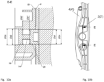
rigid pin 6 and theinternal part 7b of thesocket 7 as in the alternative embodiment represented infigs. 10a and 10b . Here, theinternal part 7b of thesocket 7 has a shape of a truncated cone with its lateral surface extending between the first socket diameter D1 and the second socket diameter D2. On the other hand, theexternal part 20 and theinternal part 19 of therigid pin 6 have also lateral walls formed by rotational surfaces of two respective truncated cones, so that the second pin diameter d2 constitutes the largest diameter of theinternal part 19 that is larger than the first pin diameter d1, which in turn is the smallest diameter of theexternal part 20. In the cross-section E-E of theinternal part 7b of thesocket 7 and therigid pin 6, shown infig. 10a , it may be seen that theexternal part 20 of therigid pin 6 has a shape of a truncated cone with a smaller diameter d1 and a larger diameter d1', while theinternal part 19 of therigid pin 6 has a shape of a truncated cone with a larger diameter d2 and a smaller diameter d2', wherein D2>d2>D1 and d2'>d1'. Consequently, the rigid pin fits within theentrance opening 11 and may not be removed through theoperational hole 12. -
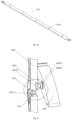
Fig. 5a shows that the above mentioned entrance position of therigid pin 6 in relation to thesocket 7 is the position in which the curvature of therail 14 coincides with theguide 13. In this position, the angle between the axis O and the axis Y2 equals an angle α1 the size of which results from the sizes of the interrelated components. In order for the first connectingassembly 5 to be in a partly engaged state, i.e. in order to introduce therigid pin 6 into theinternal part 7b of thesocket 7 through theentrance opening 11, theslat holder 4 must be rotated in relation to thelateral profile 2 so that the angle between the axis O and the axis Y2 is decreased.Fig. 5b shows a situation in which the first connectingassembly 5 is in the partly engaged state, i.e. therigid pin 6 has been introduced into theinternal part 7b of thesocket 7 and the second connectingassembly 8 has not yet been engaged. This is a situation when therigid pin 6 may still be removed from thesocket 7 by rotating it back to the angle α1 position. When the first connectingassembly 5 is in the partly engaged state (fig. 5b ), the angle between the axis O and the axis Y2 equals a defined installation angle α which is different from the angle α1. In particular, the installation angle α is smaller than the angle α1. In this position, theslat holder 4 may be turned around therigid pin 6 located in theinternal part 7b which is not divided by theprojections - In order to engage the second connecting
assembly 8, i.e. in order to snap theelastic pin 9 of theslat holder 4 in theopening 10 of thespacing rod 3, it is necessary to increase the angle between the axis O and the axis Y2 by rotating theslat holder 4 in relation to thelateral profile 2 around the axis X1 of therigid pin 6. This results in that theelastic pin 9 gets offset from thelateral profile 2 and may be engaged with thespacing rod 3. -
Fig. 5c shows a situation upon engagement of the second connectingassembly 8, when the first connectingassembly 5 is in the completely engaged state and therigid pin 6 may still be rotated around the first axis X1 within theinternal part 7b of thesocket 7 but in a limited scope. This is because the angle β between the axis O and the axis Y2 may not be reduced to equal the installation angle α due to the presence of thespacing rod 3 engaged with theslat holder 4 by means of the second connectingassembly 8. -
Fig. 5c shows a situation upon engagement of the second connectingassembly 8 when theshutter slats 1 are in their closed position. Here, theelastic pin 9 has been snapped into theopening 10 of thespacing rod 3 which required the rotation of theslat holder 4 in relation to thelateral profile 2 around the first axis X1 of therigid pin 6 located within theinternal part 7b. This rotation made the removal of therigid pin 6 through theguide 13 and the entrance opening 11 impossible. Upon said rotation, the angle β between the axis O and the axis Y2 is larger than the installation angle α, and the curvature of therail 14 does not coincide with theguide 13. -
Fig. 5d shows the detail F indicated infig. 5c , enlarged. - The components of the first connecting
assembly 5 and the second connectingassembly 8 are designed in such a way that when both assemblies are engaged, the system remains in a position that has been imparted thereto due to the frictional forces acting between the respective elements of the connecting assemblies. In order to change the position of the system for closing or opening the shutter slats, i.e. to change the angle β between the axis O and the axis Y2, it is necessary to overcome the frictional forces by suitably translating thespacing rod 3 using a suitable force. -
Fig. 5e also shows a situation when the first connectingassembly 5 is in its completely engaged state, i.e. when the second connectingassembly 8 is engaged, but theshutter slats 1 are in their open position. In this position theslat holder 4 has been rotated around therigid pin 6 located within theinternal part 7b; in this situation, the removal of therigid pin 6 through theguide 13 and theentrance opening 11 is also impossible because the angle β1 between the axis O and the axis Y2 is larger than the installation angle α. -
Fig. 9 shows a perspective view of the second connectingassembly 8 when disengaged; it comprises theelastic pin 9 located on theslat holder 4 and theopening 10 located on thespacing rod 3. Theelastic pin 9 has a structure enabling snap-coupling with theopening 10 in which theelastic pin 9 remains rotatable. In the described embodiment, theelastic pin 9 is composed of two spaced apart elastic formations, half-circular in cross-section and having thickened endings. Their elasticity enables snap-coupling in thecircular openings 10. The coupling is detachable. - The installation of the shutter system shown in
figs. 1a and 1b is done as follows. - The individual sections of the
lateral profiles 2, 2' are connected with each other and mounted to fixed supports so that the fourth walls S4 adjoin the supports and the third walls S3 are in front, i.e. facing the operator. - Then, the
slat holders 4 are fitted on eachshutter slat 1 symmetrically on both ends, so that therigid pins 6, 6' and theelastic pins 9, 9' are respectively coaxial. - Next, the
shutter slats 1 may be connected on both sides with thesockets 7, 7' of the already fixedlateral profiles 2, 2'. In order to do this, eachshutter slat 1 should be oriented so that theelastic pins 9, 9' are above therigid pins 6, 6' and in front, i.e. facing the third wall S3 of thelateral profile 2, 2'. Therigid pins 6, 6' may then be introduced into thesockets 7, 7' by first turning theslat holders 4, 4' in relation to thelateral profile 2, 2' in order to find such an angular position of the axis O, O' of theslat holders 4, 4' in relation to the axes Y2, Y2' in which therail 14, 14' coincides with theguide 13, 13'. This is a starting position for introducing therigid pins 6, 6' into thesockets 7, 7' by a moving them along an arc (fig. 5a ). As mentioned above, this is the only angular position in which therigid pins 6, 6' may be introduced into thesockets 7, 7' and removed therefrom in a non-destructive way. - The installation of the system is completed by fixing the individual sections of the
spacing rods 3, 3'. As explained above, in order to do this, eachslat holder 4, 4' should be rotated in relation to thelateral profile 2, 2' around the axis X1, X1' of therigid pin 6, 6' and then theelastic pins 9, 9' may be introduced into their sockets, i.e. theopenings 10, 10'. Thespacing rods 3, 3' should be fixed in such a way that in the closed position of the system their wavy walls adjoin the wavy third walls S3 of thelateral profiles 2, 2' and the neighboringslat holders 4, 4' overlap each other by their indentations in the side walls shown infig. 4a . Finally, the individual sections of thespacing rods 3, 3' may be connected to each other. - As explained above, upon fixing the
spacing rods 3, 3', the removal of therigid pins 6, 6' from thesockets 7, 7' is impossible, which protects the system from theshutter slats 1 falling out during normal use. - A specific advantage of the invention is that the
lateral profiles 2, 2' may be first separately fixed to their supports and then thelong shutter slats 1 may be fixed one by one which makes the system easy to be installed by one person. - The
lateral slats 2, 2', thespacing rods 3, 3' and theslat holders 4, 4' may be made e.g. of metal, plastic or wood, or any other suitable material. - List of references in the figures:
- 1 - shutter slats
- 2, 2' - lateral profiles being their respective mirror reflections
- 3, 3'- spacing rods, identical or being their respective mirror reflections
- 4, 4' - slat holders being their respective mirror reflections
- W, W' - slat holder cavities being their respective mirror reflections
- P, P' - front walls of the slat holders being their respective mirror reflections
- 5, 5' - first connecting assemblies being their respective mirror reflections
- 6, 6' - rigid pins being their respective mirror reflections
- 7, 7' - sockets of the first connecting
assemblies 5, 5', being their respective mirror reflections - 7a, 7a' - external parts of the
sockets 7, 7', being their respective mirror reflections - 7b, 7b' - internal parts of the
sockets 7, 7', being their respective mirror reflections - 8, 8' - second connecting assemblies, identical
- 9, 9' - elastic pins, identical
- 10, 10' - openings of the second connecting assemblies, identical
- 11, 11' - entrance holes of the
sockets 7, 7', being their respective mirror reflections - 12, 12' - operational holes of the
sockets 7, 7', being their respective mirror reflections - 13, 13' - guides of the
sockets 7, 7', being their respective mirror reflections - 14, 14' - rails of the
rigid pins 6, 6' being their respective mirror reflections - 15a, 15b; 15a', 15b' - projections of the
sockets 7, 7', being their respective mirror reflections - 16a, 16b; 16a', 16b' - walls of the
projections - 17, 17' - internal passages of the
sockets 7, 7', being their respective mirror reflections - 18, 18' - external passages of the
sockets 7, 7', being their respective mirror reflections - 19, 19' - internal parts of the
rigid pins 6, 6', being their respective mirror reflections - 20, 20' - external parts of the
rigid pins 6, 6', being their respective mirror reflections - S1, S1' - first walls of the
lateral profiles 2, 2', being their respective mirror reflections - S2, S2' - second walls of the
lateral profiles 2, 2', being their respective mirror reflections - S3, S3' - third walls of the
lateral profiles 2, 2', being their respective mirror reflections - S4, S4' - fourth walls of the
lateral profiles 2, 2', being their respective mirror reflections X - axis of theshutter slat 1 - X1, X1' -first axis of the
rigid pin 6, 6', i.e. the axis of rotation of theslat holder 4, 4' in relation to thelateral profile - X2, X2'- second axis of the
elastic pin 9, 9', i.e. the axis of rotation of theslat holder 4, 4' in relation to thespacing rod 3, 3' - Y2, Y2' - axis of the
lateral profile 2, 2' - Y3, Y3'- axis of the
spacing rod 3, 3' - O, O' - axis of the slat holder lying in the front wall P, P' and intersecting the axes X1, X2; X1', X2'
- α - defined installation angle between the axis O, O' and the axis Y2, Y2'
- α1 - angle between the axis O, O' and axis Y2, Y2' before engagement of the first connecting assemblies
- β - angle between the axis O, O' and axis Y2, Y2' in the completely engaged state of the first connecting assemblies, in the closed position of the system
- β1 - angle between the axis O, O' and axis Y2, Y2' in the completely engaged state of the first connecting assemblies, in the open position of the system.
Claims (11)
- A connecting device for shutter slats, the connecting device comprising a fixed lateral profile (2) having a longitudinal axis (Y2) and a spacing rod (3) having a longitudinal axis (Y3) parallel to the axis (Y2), the device further comprising at least one slat holder (4) connectable to the shutter slat, the slat holder (4) having a front wall (P) facing the lateral profile (2), on which front wall a longitudinal axis (O) of the slat holder lies, each slat holder (4) being releasably engageable with the lateral profile (2) by means of a first connecting assembly (5), and each slat holder (4) being releasably engageable with the spacing rod (3) by means of a second connecting assembly (8), so that each slat holder (4) is rotatable in relation to the lateral profile (2) and to the spacing rod (3), characterized in that the first connecting assembly (5) may be in a partly engaged state and in a completely engaged state, the first connecting assembly (5) being in the partly engaged state when the slat holder (4) is engaged with the lateral profile (2) and the second connecting assembly (8) is not engaged, and in said partly engaged state there is only one position of the slat holder (4) in relation to the lateral profile (2) in which the first connecting assembly (5) may be disengaged, said only one position being such that the angle between the axis (O) of the slat holder and the axis (Y2) of the lateral profile equals a defined installation angle (α), while upon engagement of the second connecting assembly (8), the first connecting assembly (5) is in the completely engaged state and the angle between the axis (O) of the slat holder and the axis (Y2) of the lateral profile is larger than said defined installation angle (α).
- The connecting device according to claim 1, characterized in that the first connecting assembly (5) comprises a rigid pin (6) protruding from the front wall (P) of the slat holder (4) and a socket (7) located on the lateral profile (2), the rigid pin (6) having a first axis (X1) perpendicular to the axis (Y2) of the lateral profile (2), and the second connecting assembly (8) comprises an elastic pin (9) protruding from the front wall (P) of the slat holder (4) and an opening (10) located on the spacing rod (3), the elastic pin (9) having a second axis (X2) perpendicular to the axis (Y3) of the spacing rod (3), the first axis and the second axis intersecting said front wall (P) at points laying on the axis of the slat holder.
- The connecting device according to claim 2, characterized in that the lateral profile (2) has a first wall (S1) facing the front wall (P) of the slat holder (4) and a second wall (S2) perpendicular to said first wall (S1), the rigid pin (6) comprises an internal part (20) and an external part (19) that are connected by a rail-shaped narrowing (14) having a form of a section of a cylinder having the second axis (X2), and in that the socket (7) has an external part (7a) with an entry hole (11) located on the second wall (S2) of the lateral profile (2), the entry hole (11) being shaped to enable introduction of the rigid pin (6) into the socket (7), said external part (7a) comprising a guide (13) having a curved shape adapted to receive said rail-shaped narrowing (14) during the introduction of the rigid pin (6) into the socket (7) through the entry hole (11), and the socket (7) having an internal part (7b) with an operational hole (12) located on said first wall (S1) of the lateral profile (2), wherein upon the engagement of the first connecting assembly (5), the rigid pin (6) is located in said internal part (7b) of the socket (7) and it connects pivotally with said internal part (7b) through said operational hole (12).
- The connecting device according to claim 3, characterized in that the lateral profile (2) has a third wall (S3) opposite to its second wall (S2), the third wall (S3) having a wavy shape, and the wall of the spacing rod (3) facing the lateral profile (2) has a wavy shape matching the shape of said third wall (S3) .
- The connecting device according to claim 3, characterized in that the guide (13) is formed by a space located between a first projection (15a) protruding inwardly from the external part (7a) of the socket (7) and an opposite second projection (15b), and in that the guide (13) with the first and second projections (15a, 15b) divide the external part (7a) of the socket into an internal passage (17) located away from the first wall (S1) and an external passage (18) located close to the first wall (S1).
- The connecting device according to claim 5, characterized in that during the engagement operation of the first connecting assembly (5), the internal part (19) of the rigid pin (6) is located in said internal passage (17) and the external part (20) of the rigid pin (6) is located in said external passage (18).
- The connecting device according to claim 1, characterized in that the internal part (7b) of the socket (7) is formed by a fragment of a cylindrical wall of the socket having a first socket diameter (D1) defining the operational hole (12), and a fragment of a cylindrical wall of the socket having a second socket diameter (D2), the second socket diameter (D2) being larger than the first socket diameter (D1), wherein the external part (20) of the rigid pin (6) has a shape of a cylinder having a first pin diameter (d1), while its internal part(19) has a shape of a cylinder having a second pin diameter (d2), wherein (d2) > (d1).
- The connecting device according to claim 1, characterized in that the internal part (7b) of the socket (7) has a shape of a truncated cone having a first socket diameter (D1) defining the operational hole (12) and a second socket diameter (D2), wherein the external part (20) of the rigid pin (6) has a shape of a truncated cone having a small first pin diameter (d1), while its internal part (19) has a shape of a truncated cone having a large second pin diameter (d2), wherein (d2) > (d1), so that the rigid pin (6) fits in the internal part (7b) of the socket (7).
- The connecting device according to claim 1 or 2, characterized in that the lateral profile (2) is composed of individual sections mutually connectable by projections and corresponding recesses located at their respective ends.
- The connecting device according to claim 1 or 2, characterized in that the spacer rod (3) is composed of individual sections mutually connectable by form-fitting snap connectors located at their respective ends.
- A shutter system comprising at least one horizontal pivotable shutter slat (1) having a longitudinal axis (X), characterized in that the system further comprises two connecting devices (U, U') according to any of claims 1-10, said two connecting devices (U, U') being their mutual mirror reflections and each shutter slat (1) being fitted by its one end to one of said connecting devices (U) and by its other end to the other of said two connecting devices (U'), wherein each slat holder (4, 4') has a cavity (W, W') the shape of which corresponds to the cross-section of the shutter slats (1).
Applications Claiming Priority (1)
| Application Number | Priority Date | Filing Date | Title |
|---|---|---|---|
| PL441143A PL441143A1 (en) | 2022-05-09 | 2022-05-09 | Connecting device for shutter slats and a shutter system containing two such connecting devices |
Publications (1)
| Publication Number | Publication Date |
|---|---|
| EP4276257A1 true EP4276257A1 (en) | 2023-11-15 |
Family
ID=87202309
Family Applications (1)
| Application Number | Title | Priority Date | Filing Date |
|---|---|---|---|
| EP23020214.5A Withdrawn EP4276257A1 (en) | 2022-05-09 | 2023-05-08 | A connecting device for shutter slats and a shutter system comprising two such connecting devices |
Country Status (2)
| Country | Link |
|---|---|
| EP (1) | EP4276257A1 (en) |
| PL (1) | PL441143A1 (en) |
Citations (2)
| Publication number | Priority date | Publication date | Assignee | Title |
|---|---|---|---|---|
| CA2224834C (en) * | 1997-12-15 | 2003-04-01 | Vinylbilt Shutters Systems Inc. | Louver control in a movable louver assembly |
| FR2986819A1 (en) | 2012-02-09 | 2013-08-16 | Laurent Chevillard | DEVICE FOR CONNECTION BETWEEN BLADE AND FRAME FOR THE PRODUCTION OF A PANEL WITH ORIENTABLE BLADES AND PANEL OBTAINED |
-
2022
- 2022-05-09 PL PL441143A patent/PL441143A1/en unknown
-
2023
- 2023-05-08 EP EP23020214.5A patent/EP4276257A1/en not_active Withdrawn
Patent Citations (2)
| Publication number | Priority date | Publication date | Assignee | Title |
|---|---|---|---|---|
| CA2224834C (en) * | 1997-12-15 | 2003-04-01 | Vinylbilt Shutters Systems Inc. | Louver control in a movable louver assembly |
| FR2986819A1 (en) | 2012-02-09 | 2013-08-16 | Laurent Chevillard | DEVICE FOR CONNECTION BETWEEN BLADE AND FRAME FOR THE PRODUCTION OF A PANEL WITH ORIENTABLE BLADES AND PANEL OBTAINED |
Also Published As
| Publication number | Publication date |
|---|---|
| PL441143A1 (en) | 2023-11-13 |
Similar Documents
| Publication | Publication Date | Title |
|---|---|---|
| US11549533B2 (en) | Pin and grommet fastener accommodating two directional offset and related methods | |
| US6244012B1 (en) | Muntin grid and joiner | |
| US7516927B2 (en) | Device for locking an electric apparatus onto a supporting rail | |
| US6401391B2 (en) | Louver control in a movable louver assembly | |
| RU2337222C2 (en) | Link for auxiliary arrangement for windows and doors | |
| KR101773024B1 (en) | Connector and toy set including them | |
| WO1997017557A2 (en) | Energy management chain | |
| EP3061372B1 (en) | Quick-connecting device and shower room component | |
| US9803420B2 (en) | Closing element for roller shutter and movable wall for roller shutter comprising the closing element | |
| DE102010039706A1 (en) | Electrical connector | |
| WO2001069129A1 (en) | Built-in illuminator comprising a supporting ring for additional components | |
| KR101758747B1 (en) | 2-axis hinge | |
| EP3239450A1 (en) | Actuation device for the slats of a shutter | |
| UA95135C2 (en) | Device for force transmission assembly for a window, door or similar | |
| EP0432828A1 (en) | Assembly of an end support and an operating crank for rotatable slats or blades of shutters | |
| CA2629658C (en) | Toggle bar | |
| EP1207265A2 (en) | Shutter | |
| KR102307146B1 (en) | Connection device of profile element | |
| CN220275269U (en) | Lock catch structure and furniture | |
| ES2304679T3 (en) | DRIVE ASSEMBLY FOR WINDOW AND DOOR FRAMES. | |
| TWI871910B (en) | Door and window devices | |
| KR102416134B1 (en) | Linked Project Window | |
| EP4386218B1 (en) | Pin and grommet fastener accommodating two directional offset and related methods | |
| KR200241668Y1 (en) | hinge | |
| KR100571064B1 (en) | Chain Block Toys |
Legal Events
| Date | Code | Title | Description |
|---|---|---|---|
| PUAI | Public reference made under article 153(3) epc to a published international application that has entered the european phase |
Free format text: ORIGINAL CODE: 0009012 |
|
| STAA | Information on the status of an ep patent application or granted ep patent |
Free format text: STATUS: THE APPLICATION HAS BEEN PUBLISHED |
|
| AK | Designated contracting states |
Kind code of ref document: A1 Designated state(s): AL AT BE BG CH CY CZ DE DK EE ES FI FR GB GR HR HU IE IS IT LI LT LU LV MC ME MK MT NL NO PL PT RO RS SE SI SK SM TR |
|
| STAA | Information on the status of an ep patent application or granted ep patent |
Free format text: STATUS: REQUEST FOR EXAMINATION WAS MADE |
|
| RBV | Designated contracting states (corrected) |
Designated state(s): AL AT BE BG CH CY CZ DE DK EE ES FI FR GB GR HR HU IE IS IT LI LT LU LV MC ME MK MT NL NO PL PT RO RS SE SI SK SM TR |
|
| 17P | Request for examination filed |
Effective date: 20240508 |
|
| GRAP | Despatch of communication of intention to grant a patent |
Free format text: ORIGINAL CODE: EPIDOSNIGR1 |
|
| STAA | Information on the status of an ep patent application or granted ep patent |
Free format text: STATUS: GRANT OF PATENT IS INTENDED |
|
| INTG | Intention to grant announced |
Effective date: 20240806 |
|
| RIN1 | Information on inventor provided before grant (corrected) |
Inventor name: JURGIELEWICZ, MICHAL Inventor name: GALAS, ADAM |
|
| STAA | Information on the status of an ep patent application or granted ep patent |
Free format text: STATUS: THE APPLICATION IS DEEMED TO BE WITHDRAWN |
|
| 18D | Application deemed to be withdrawn |
Effective date: 20241207 |