EP4276159A1 - Steel plant facility measurement system, coke oven, and coke production method - Google Patents
Steel plant facility measurement system, coke oven, and coke production method Download PDFInfo
- Publication number
- EP4276159A1 EP4276159A1 EP22752618.3A EP22752618A EP4276159A1 EP 4276159 A1 EP4276159 A1 EP 4276159A1 EP 22752618 A EP22752618 A EP 22752618A EP 4276159 A1 EP4276159 A1 EP 4276159A1
- Authority
- EP
- European Patent Office
- Prior art keywords
- wireless transmission
- coke oven
- measurement system
- relay
- sensor
- Prior art date
- Legal status (The legal status is an assumption and is not a legal conclusion. Google has not performed a legal analysis and makes no representation as to the accuracy of the status listed.)
- Pending
Links
- 238000005259 measurement Methods 0.000 title claims abstract description 73
- 239000000571 coke Substances 0.000 title claims description 108
- 238000004519 manufacturing process Methods 0.000 title claims description 10
- 229910000831 Steel Inorganic materials 0.000 title 1
- 239000010959 steel Substances 0.000 title 1
- 230000005540 biological transmission Effects 0.000 claims abstract description 90
- 238000010248 power generation Methods 0.000 claims abstract description 43
- 238000006243 chemical reaction Methods 0.000 claims abstract description 35
- 238000009434 installation Methods 0.000 abstract description 13
- 238000012423 maintenance Methods 0.000 abstract description 11
- 239000003245 coal Substances 0.000 description 71
- 238000002485 combustion reaction Methods 0.000 description 47
- 238000003763 carbonization Methods 0.000 description 18
- 238000010586 diagram Methods 0.000 description 10
- 238000004939 coking Methods 0.000 description 7
- 238000000034 method Methods 0.000 description 7
- 230000008054 signal transmission Effects 0.000 description 6
- 238000009529 body temperature measurement Methods 0.000 description 5
- 238000004891 communication Methods 0.000 description 5
- 238000001816 cooling Methods 0.000 description 5
- 238000007689 inspection Methods 0.000 description 5
- 230000000903 blocking effect Effects 0.000 description 3
- 239000003990 capacitor Substances 0.000 description 2
- 238000009826 distribution Methods 0.000 description 2
- 230000000694 effects Effects 0.000 description 2
- 230000002708 enhancing effect Effects 0.000 description 2
- 239000002994 raw material Substances 0.000 description 2
- 239000004065 semiconductor Substances 0.000 description 2
- 238000003860 storage Methods 0.000 description 2
- 230000005856 abnormality Effects 0.000 description 1
- 230000001133 acceleration Effects 0.000 description 1
- 238000010000 carbonizing Methods 0.000 description 1
- 239000000919 ceramic Substances 0.000 description 1
- 239000002826 coolant Substances 0.000 description 1
- 238000001514 detection method Methods 0.000 description 1
- 239000000446 fuel Substances 0.000 description 1
- 229920006395 saturated elastomer Polymers 0.000 description 1
- XLYOFNOQVPJJNP-UHFFFAOYSA-N water Substances O XLYOFNOQVPJJNP-UHFFFAOYSA-N 0.000 description 1
Images


Classifications
-
- G—PHYSICS
- G01—MEASURING; TESTING
- G01K—MEASURING TEMPERATURE; MEASURING QUANTITY OF HEAT; THERMALLY-SENSITIVE ELEMENTS NOT OTHERWISE PROVIDED FOR
- G01K1/00—Details of thermometers not specially adapted for particular types of thermometer
- G01K1/02—Means for indicating or recording specially adapted for thermometers
- G01K1/024—Means for indicating or recording specially adapted for thermometers for remote indication
-
- G—PHYSICS
- G08—SIGNALLING
- G08C—TRANSMISSION SYSTEMS FOR MEASURED VALUES, CONTROL OR SIMILAR SIGNALS
- G08C17/00—Arrangements for transmitting signals characterised by the use of a wireless electrical link
- G08C17/02—Arrangements for transmitting signals characterised by the use of a wireless electrical link using a radio link
-
- C—CHEMISTRY; METALLURGY
- C10—PETROLEUM, GAS OR COKE INDUSTRIES; TECHNICAL GASES CONTAINING CARBON MONOXIDE; FUELS; LUBRICANTS; PEAT
- C10B—DESTRUCTIVE DISTILLATION OF CARBONACEOUS MATERIALS FOR PRODUCTION OF GAS, COKE, TAR, OR SIMILAR MATERIALS
- C10B45/00—Other details
-
- F—MECHANICAL ENGINEERING; LIGHTING; HEATING; WEAPONS; BLASTING
- F27—FURNACES; KILNS; OVENS; RETORTS
- F27D—DETAILS OR ACCESSORIES OF FURNACES, KILNS, OVENS OR RETORTS, IN SO FAR AS THEY ARE OF KINDS OCCURRING IN MORE THAN ONE KIND OF FURNACE
- F27D21/00—Arrangement of monitoring devices; Arrangement of safety devices
-
- G—PHYSICS
- G01—MEASURING; TESTING
- G01K—MEASURING TEMPERATURE; MEASURING QUANTITY OF HEAT; THERMALLY-SENSITIVE ELEMENTS NOT OTHERWISE PROVIDED FOR
- G01K1/00—Details of thermometers not specially adapted for particular types of thermometer
- G01K1/02—Means for indicating or recording specially adapted for thermometers
-
- H—ELECTRICITY
- H04—ELECTRIC COMMUNICATION TECHNIQUE
- H04Q—SELECTING
- H04Q9/00—Arrangements in telecontrol or telemetry systems for selectively calling a substation from a main station, in which substation desired apparatus is selected for applying a control signal thereto or for obtaining measured values therefrom
-
- G—PHYSICS
- G08—SIGNALLING
- G08C—TRANSMISSION SYSTEMS FOR MEASURED VALUES, CONTROL OR SIMILAR SIGNALS
- G08C2201/00—Transmission systems of control signals via wireless link
- G08C2201/40—Remote control systems using repeaters, converters, gateways
-
- H—ELECTRICITY
- H04—ELECTRIC COMMUNICATION TECHNIQUE
- H04Q—SELECTING
- H04Q2209/00—Arrangements in telecontrol or telemetry systems
- H04Q2209/80—Arrangements in the sub-station, i.e. sensing device
- H04Q2209/88—Providing power supply at the sub-station
- H04Q2209/886—Providing power supply at the sub-station using energy harvesting, e.g. solar, wind or mechanical
Definitions
- the present disclosure relates to a measurement system for steelworks equipment, a coke oven, and a coke production method.
- sensors are used for measurement for various purposes such as operation status check, abnormality detection, and equipment maintenance.
- Wireless transmission of signals output from sensors is also performed in recent years. Wireless signal transmission is advantageous in that it increases the degree of freedom in sensor installation because there is no need to lay cables for signal transmission.
- sensors for wirelessly transmitting signals hereafter also referred to as “wireless sensors”
- wireless sensors to have a power generation function to enable stand-alone power supply for a long period of time.
- JP 2013-122718 A proposes a wireless sensor in which a vibration power generation element, a sensor, and an antenna for wireless transmission are mounted in an airtight package.
- JP 2016-157356 A proposes a wireless sensor in which a solar cell module, a sensor, and an antenna for wireless transmission are mounted in a package.
- JP 2018-200518 A proposes a thermoelectric power generator transmitter including a thermoelectric power generation module, a sensor, and a wireless module.
- a sensor can be supplied with power from a power generation device mounted integrally with the sensor. This eliminates the need for installation of power supply cables and maintenance work such as battery replacement.
- the object to be measured tends to be a very wide range, and the environment is usually harsh, such as high temperatures. Eliminating the need for installation of power supply cables and maintenance work such as battery replacement is therefore very advantageous.
- the wireless sensor proposed in PTL 1 uses a vibration power generation element as a power source, and thus can only be used in locations where a certain amount of vibration occurs constantly.
- the wireless sensor proposed in PTL 2 uses a solar cell as a power source, and thus can only be used in environments and time periods in which sufficient light is incident. To solve this problem, PTL 2 proposes to provide a power storage that stores the power generated by the solar cell module. However, a large power storage is required in order to stably continue operation even in environments in which light is not incident, such as at night. This causes an increase of the size of the wireless sensor.
- thermoelectric power generation does not reveal specifically how thermoelectric power generation is applied to steelworks equipment.
- the measurement system for steelworks equipment is suitable for use in various production equipment such as coke ovens.
- the measurement system according to Embodiment 1 of the present disclosure includes the following components (1) to (6):
- the conversion device (3) and the wireless transmission device (4) are driven by power generated by the thermoelectric power generation device (1).
- the thermoelectric power generation device is a device capable of generating power by utilizing the temperature difference between one side (high temperature side) and the other side (low temperature side) of the thermoelectric power generation device.
- the thermoelectric power generation device typically includes a thermoelectric element that combines a p-type semiconductor and an n-type semiconductor.
- thermoelectric power generation device is not limited, and any thermoelectric power generation device may be used.
- the use of the thermoelectric power generation device makes it possible to generate power using heat from various equipment in a steelworks and drive the conversion device and the wireless transmission device using the generated power.
- the heat source for generating power in the thermoelectric power generation device is not limited, and any heat source may be used. It is preferable to use a high temperature part of the steelworks equipment as the heat source. That is, it is preferable to directly or indirectly install the high temperature side of the thermoelectric power generation device in the high temperature part of the steelworks equipment.
- the thermoelectric power generation device preferably includes a heat receiving sheet on the high temperature side, from the viewpoint of enhancing the utilization efficiency of heat from the heat source.
- the heat receiving sheet for example, a metallic sheet or a ceramic sheet may be used.
- the thermoelectric power generation device preferably includes a cooling means on the low temperature side, from the viewpoint of enhancing the power generation efficiency.
- a cooling means for example, one or both of a heat radiating member such as heat radiating fins and a heat exchanger that performs cooling by exchanging heat with a cooling medium such as water or oil may be used.
- the sensor is not limited, and any sensor may be used depending on the object to be measured.
- the sensor for example, at least one selected from the group consisting of a temperature sensor, a pressure sensor, a flow sensor, a vibration sensor, and an acceleration sensor may be used.
- the temperature sensor include a thermocouple, a resistance temperature detector, and a thermistor.
- the number of sensors is not limited, and may be any number of 1 or 2 or more. It is preferable to arrange a plurality of sensors at different points, from the viewpoint of obtaining information about the distribution of measured values. A plurality of sensors may be arranged at the same point, from the viewpoint of redundancy and accuracy improvement. From the viewpoint of measuring the distribution of measured values in more detail, a larger number of sensors is better, and accordingly no upper limit is placed on the number of sensors. Since the cost increases with the increase of the number of sensors, however, the number of sensors is preferably 1000 or less from the viewpoint of cost effectiveness.
- the conversion device converts a signal output from the sensor into a wirelessly transmittable signal.
- the conversion device is not limited, and any device such as a commercially available converter may be used.
- the wireless transmission device wirelessly transmits the signal converted by the conversion device.
- the wireless transmission device is not limited, and any device capable of signal transmission, such as a commercially available device, may be used.
- thermoelectric power generation devices may supply power to a plurality of conversion devices and a plurality of wireless transmission devices. Signals output from a plurality of sensors may be collectively transmitted by one conversion device and one wireless transmission device.
- thermoelectric power generation device it is also preferable to mount the thermoelectric power generation device, the conversion device, and the wireless transmission device in one package. Mounting these components in one package facilitates handling, and also facilitates installation of a heat radiating member and a light shielding member as described later.
- thermoelectric-wireless transmission unit one package in which the thermoelectric power generation device, the conversion device, and the wireless transmission device are mounted is referred to as a "thermoelectric-wireless transmission unit" for the sake of convenience.
- the measurement system for steelworks equipment preferably includes a heat radiating member for cooling one or both of the conversion device and the wireless transmission device.
- Steelworks equipment is often at high temperatures, as mentioned above.
- the use of the heat radiating member can suppress the temperature rise of the conversion device and the wireless transmission device.
- the heat radiating member for example, heat radiating fins and the like may be used.
- the heat radiating member can also serve as cooling means on the low temperature side of the thermoelectric power generation device.
- the thermoelectric power generation device, the conversion device, and the wireless transmission device are mounted in one package (thermoelectric-wireless transmission unit), it is possible to cool the thermoelectric power generation device, the conversion device, and the wireless transmission device by providing the heat radiating member in the thermoelectric-wireless transmission unit.
- the measurement system for steelworks equipment preferably includes a light shielding member for blocking direct sunlight.
- a light shielding member for blocking direct sunlight For example, in the case where the measurement system is installed outdoors, such as above a coke oven, direct sunlight can cause the device temperature to rise. Such temperature rise can be suppressed by blocking sunlight using the light shielding member.
- the light shielding member is preferably configured to block direct sunlight to at least one of the thermoelectric power generation device, the conversion device, and the wireless transmission device.
- the thermoelectric power generation device, the conversion device, and the wireless transmission device are mounted in one package (thermoelectric-wireless transmission unit), it is possible to suppress the temperature rise of the thermoelectric power generation device, the conversion device, and the wireless transmission device by providing the light shielding member in the thermoelectric-wireless transmission unit.
- the measurement system for steelworks equipment preferably includes both the heat radiating member and the light shielding member, from the viewpoint of preventing the temperature rise more effectively.
- the light shielding member is preferably installed above the heat radiating member. This prevents the heat radiating member from being exposed to direct sunlight, and consequently enables the heat radiating member to function more effectively.
- the measurement system according to the present disclosure further includes the relay device that relays the signal transmitted from the wireless transmission device.
- the relay device that relays the signal transmitted from the wireless transmission device.
- the relay means is not limited, and any means capable of relaying the signal transmitted from the wireless transmission device may be used.
- the number of relay devices is not limited, and any number of relay devices, i.e. one or two or more relay devices, may be used. In the case where the distance between the sensor and the reception device is long or in the case where the condition of radio waves, etc. used for wireless transmission is poor, it is preferable to use a plurality of relay devices.
- the reception device receives the signal relayed by the relay device.
- the signal transmitted from the wireless transmission device is basically relayed by the relay device, it is not always necessary to relay the signal by the relay device.
- a signal from the wireless transmission device installed at a position near the reception device can be directly received by the reception device without via the relay device.
- the reception device is thus configured to receive one or both of the signal transmitted from the wireless transmission device and the signal relayed by the relay device.
- the reception device is not limited, and any device capable of signal reception, such as a commercially available reception device, may be used.
- the conversion device and the wireless transmission device are driven by the power generated by the thermoelectric power generation device. This eliminates the need for wiring, batteries, and the like for supplying power to the conversion device and the wireless transmission device.
- the measurement system according to the present disclosure can thus be easily installed and operated even in a location where wiring and maintenance such as battery replacement are difficult.
- the measurement system according to the present disclosure preferably further includes a capacitor for temporarily storing the power generated by the thermoelectric power generation device.
- the senor is preferably used to measure the temperature of a combustion chamber. Since the temperature of the coke oven, particularly the combustion chamber, is considerably high, a thermocouple is preferably used as the sensor.
- Signal transmission may be performed at any interval.
- the power generated by the thermoelectric power generation device may be temporarily stored in the capacitor, and a signal may be transmitted when the stored power exceeds a certain amount.
- the transmission interval depends on the temperature of the heat source. It is therefore desirable to adjust the installation position of the thermoelectric power generation device so that the transmission interval will not be excessively long.
- the transmission interval is preferably 600 s or less, and more preferably 60 s or less. If the transmission interval is excessively short, the power consumption is excessively high. Accordingly, the transmission interval is preferably 0.1 s or more, and more preferably 1 s or more.
- Each device included in the measurement system according to the present disclosure is preferably installed at a position where the temperature during operation does not exceed the heat resistant temperature of the device, because the oven top temperature is considerably high during operation of the coke oven.
- electronic devices such as the conversion device and the wireless transmission device are preferably installed at positions where the temperature is 80 °C or less.
- the oven top temperature of the coke oven during operation is measured beforehand, and the electronic devices are installed at positions where the temperature is 80 °C or less.
- the electronic devices such as the conversion device and the wireless transmission device are preferably installed at positions where the temperature is 0 °C or more.
- the distance from the wireless transmission device to the location where the temperature of the coke oven is managed is at least several tens of meters.
- a coal charging vehicle for charging coal into the coke oven, etc. travel, and there are many obstacles that interfere with wireless communication.
- the use of the relay device enables stable signal transmission and reception even in such an environment.
- the number of relay devices is preferably 2 or more and more preferably 3 or more, from the viewpoint of stability of transmission and reception. If the number of relay devices is excessively large, the effect is saturated, and the cost increases.
- the number of relay devices is therefore preferably 10 or less, and more preferably 5 or less.
- the number of relay devices is further preferably 4, from the viewpoint of the balance between cost and stability.
- a deck for maintenance and inspection is provided on top of a typical coke oven. Accordingly, the relay device is preferably installed on the deck.
- the reception device can be installed at any position.
- the reception device may be installed at a position away from the coke oven, such as the location where the temperature of the coke oven is managed (e.g. control room).
- the reception device may be installed at a position closer to the coke oven, such as the deck on top of the coke oven, from the viewpoint of enabling stable reception while reducing the number of relay devices required.
- the temperature of the coke oven for example, the temperature of the combustion chamber
- the temperature of the coke oven can be measured using the measurement system described above.
- the method of controlling the combustion state is not limited, and any method, such as adjusting the amount of fuel supplied to the combustion chamber, may be used.
- the adjustment of the combustion state is preferably performed for each combustion chamber.
- a target temperature is determined for each combustion chamber beforehand, and the combustion state of the combustion chamber is adjusted based on the difference between the measured temperature of the combustion chamber and the target temperature.
- the method of determining the target temperature is not limited, and may be any method including various known methods. For example, the time required for coking (actual coking time) is obtained from actual operation results for each carbonization chamber included in the coke oven, and the target temperature is determined from the difference from the target coking time.
- a plurality of carbonization chambers and a plurality of combustion chambers are alternately arranged continuously, as illustrated in FIG. 1 .
- coking in a carbonization chamber is influenced by the temperatures of a plurality of combustion chambers adjacent to the carbonization chamber. It is therefore preferable to determine the target temperature of each combustion chamber based on the influence of the temperature of the combustion chamber on the plurality of carbonization chambers.
- the foregoing control may be performed based on a database obtained by collecting, using the measurement system for steelworks equipment according to the present disclosure, the relationship between the temperature of each combustion chamber and the time actually required for coking (coking time).
- coking time refers to the time from when coal is charged into the carbonization chamber to when the coal is carbonized and turned into coke.
- FIG. 1 is a schematic diagram illustrating an example of the structure of a coke oven.
- a coke oven 100 has a structure in which carbonization chambers 101 for storing and carbonizing coal and combustion chambers 102 for supplying heat to the carbonization chambers 101 are alternately arranged in the oven width direction. Heat is supplied from a combustion chamber 102 to a carbonization chamber 101 through a refractory separating the carbonization chamber and the combustion chamber.
- a typical coke oven in a steelworks includes at least several tens of carbonization chambers, and its length L in the oven width direction is several hundred meters.
- the size of each of the carbonization chamber 101 and the combustion chamber 102 is, for example, about 7 m in height H and about 16 m in depth D.
- Coal charging vehicle rails 103 are laid on top of the coke oven, and a coal charging vehicle 107 for charging coal into each carbonization chamber 101 runs on the coal charging vehicle rails 103.
- a coal tower 108 for supplying coal to the coal charging vehicle 107 is located between or at the end of a plurality of coke oven batteries.
- thermocouple In such a coke oven including many combustion chambers, temperature measurement is necessary in order to control the temperature of each combustion chamber.
- a sensor thermocouple
- the temperature is measured by the measurement system according to the present disclosure.
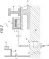
- FIG. 2 is a schematic diagram illustrating a measurement system 1 for steelworks equipment (hereinafter "measurement system 1") according to an embodiment of the present disclosure.
- the measurement system 1 includes a thermoelectric-wireless transmission unit 10 in which a thermoelectric power generation device, a conversion device, and a wireless transmission device are mounted in one package, a thermocouple 20 as a sensor, and a relay device 30.
- the measurement system 1 is installed on top of the coke oven 100, i.e. on or above the coke oven 100.
- the coal charging vehicle rails 103 are laid on top of the coke oven, and the coal charging vehicle 107 for charging coal into each carbonization chamber 101 runs on the coal charging vehicle rails 103, as mentioned above. It is therefore necessary to install the devices so as not to interfere with the running of the coal charging vehicle 107.
- the thermoelectric-wireless transmission unit 10 is installed on coal charging vehicle rail girders 104 laid as a support member for laying the coal charging vehicle rails 103.
- Heat radiating fins 11 and a light shielding member 12 for blocking direct sunlight are provided on the upper surface of the thermoelectric-wireless transmission unit 10. Thus, the temperature rise of the thermoelectric-wireless transmission unit 10 can be suppressed.
- the heat radiating fins 11 also serve to cool the low temperature side of the thermoelectric power generation device included in the thermoelectric-wireless transmission unit 10.
- thermocouple 20 is inserted inside the combustion chamber 102 through an inspection hole 105 provided in the upper part of the combustion chamber 102.
- the thermocouple 20 is connected to the conversion device in the thermoelectric-wireless transmission unit 10, and the temperature measured by the thermocouple 20 is transmitted by the wireless transmission device in the thermoelectric-wireless transmission unit 10.
- An oven top deck 106 which is a corridor for performing equipment maintenance and inspection, etc., is installed on top of the coke oven 100.
- the relay device 30 is installed on the oven top deck 106.
- FIG. 2 the parts are illustrated at different scales for the sake of convenience.
- an oven top deck is located at a height of about 8 m above the oven. Therefore, the relay device 30 can receive wireless signals from a wide range without being affected by the heat of the coke oven.
- thermoelectric-wireless transmission unit may be used for one sensor.
- one thermoelectric-wireless transmission unit may process signals from a plurality of sensors.
- the number of relay devices included in the measurement system is preferably less than the number of wireless transmission devices, more preferably less than or equal to 1/2 of the number of wireless transmission devices, and further preferably less than or equal to 1/5 of the number of wireless transmission devices.
- the number of relay devices included in the measurement system is even more preferably less than or equal to 1/10 of the number of wireless transmission devices, from the viewpoint of cost effectiveness.
- the reception device is installed at the end of the coke oven.
- the reception device may be installed in, for example, a control room for controlling the coke oven.
- the measurement system according to the present disclosure may be additionally introduced into a coke oven that already includes temperature measurement means and a temperature management system.
- the existing temperature management system may be used to perform temperature management based on the temperature measured by the measurement system according to the present disclosure.
- the relationship between the temperature measured by the existing temperature measurement means and the temperature measured by the measurement system according to the present disclosure may be determined beforehand. Then, the temperature measured by the measurement system according to the present disclosure may be converted into the temperature measured by the existing temperature measurement means based on the relationship, and temperature management may be performed based on the converted temperature.
- Embodiment 2 of the present disclosure A measurement system according to Embodiment 2 of the present disclosure will be described below. The description of the same parts as those in Embodiment 1 is omitted here.
- the measurement system according to Embodiment 2 of the present disclosure has the same structure as the measurement system according to Embodiment 1.
- more relay devices are located in a part where an obstacle stays for a longer time than in a part where the obstacle stays for a shorter time.
- the use of the relay device makes it possible to reliably monitor the measurement results even at a position away from the installation location of the sensor.
- various large-sized mobile devices are used in steelworks equipment, there is a possibility that such devices interfere with wireless communication and hinder signal relay by the relay device.
- a coal charging vehicle for charging coal as raw material into each carbonization chamber of the coke oven runs on the rails.
- the presence of a large device such as a coal charging vehicle interferes with wireless communication.
- the "part where an obstacle stays for a longer time” refers to an area where an obstacle such as a coal charging vehicle stays for a longer time
- the “part where the obstacle stays for a shorter time” refers to an area where the obstacle stays for a shorter time than in the part where the obstacle stays for a longer time.
- the entire area in which the relay devices are installed is divided into a plurality of sections, and the number of relay devices to be installed in each section is determined depending on the staying time of the obstacle in the section.
- the number (total number) of relay devices is not limited, and may be any number as long as they are arranged in the foregoing manner. Usually, the number (a plurality) of relay devices depending on the distance between the sensor and the reception device, the state of radio waves, and the like are used.
- Embodiment 2 The application of the measurement system according to Embodiment 2 to a coke oven will be described in detail below.
- a coke oven typically includes many combustion chambers, as illustrated in FIG. 1 .
- a coke oven coke oven battery
- two sensors and thermoelectric-wireless transmission units per combustion chamber a total of 130 sensors and thermoelectric-wireless transmission units, are arranged, and two to five relay devices are used to relay radio waves.
- one reception device is installed at the end of the coke oven.
- the reception device may be installed in, for example, a control room for controlling the coke oven.
- An example of the arrangement of relay devices will be described in detail below, with reference to FIG. 3 .
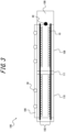
- FIG. 3 is a schematic diagram illustrating the arrangement of relay devices according to an embodiment of the present disclosure.
- a coal tower 108 is located at one end of a coke oven 100, and an intermediate deck 111 is located between a coke oven battery 109 closer to the coal tower 108 and a coke oven battery 110 farther from the coal tower 108.
- Coal charging vehicle rail girders (not illustrated) and coal charging vehicle rails 103 laid on the coal charging vehicle rail girders are installed on the coke oven 100.
- thermoelectric-wireless transmission unit 10 corresponding to each sensor is attached as illustrated in FIG. 2 .
- a plurality of relay devices 30 are installed on an oven top deck 106, and a reception device 40 is installed near the coal tower 108 at the end of the coke oven 100.
- a coal charging vehicle runs on the coal charging vehicle rails 103 and charges coal into each combustion chamber.
- the time during which the coal charging vehicle stays on the coke oven battery 110 farther from the coal tower 108 is shorter than the time during which the coal charging vehicle stays on the coke oven battery 109 closer to the coal tower 108.
- the number (N1) of relay devices 30 installed on the coke oven battery 109 is made larger than the number (N2) of relay devices 30 installed on the coke oven battery 110.
- N2 is preferably 1 to 2.
- N1 is preferably 2 to 4 and larger than N2.
- the number of relay devices 30 installed on the coke oven battery 109 is 3, and the number of relay devices 30 installed on the coke oven battery 110 is 2.
- a plurality of relay devices are installed on the coke oven made up of a plurality of coke oven batteries so as to be spaced apart in the oven width direction of the coke oven (the direction of arrow L in FIG. 1 ), and the relay device arrangement density is higher for a coke oven battery closer to the coal tower.
- the unit of region for which the number of relay devices installed is set is not limited to such, and any unit of region may be selected.
- Embodiment 3 of the present disclosure A measurement system according to Embodiment 3 of the present disclosure will be described below. The description of the same parts as those in Embodiments 1 and 2 is omitted here.
- the measurement system according to Embodiment 3 of the present disclosure has the same structure as the measurement system according to Embodiment 1 or 2.
- at least one relay device is installed on a moving obstacle.
- the use of the relay device makes it possible to reliably monitor the measurement results even at a position away from the installation location of the sensor.
- various large-sized mobile devices are used in steelworks equipment, there is a possibility that such devices interfere with wireless communication and hinder signal relay by the relay device.
- a coal charging vehicle for charging coal as raw material into each carbonization chamber of the coke oven runs on the rails.
- the presence of a large device such as a coal charging vehicle interferes with wireless communication.
- the relay devices other than the relay device installed on the obstacle may be installed at any positions without limitation, but are normally installed at locations that do not move.
- Embodiment 3 The application of the measurement system according to Embodiment 3 to a coke oven will be described in detail below.
- An oven top deck 106 which is a corridor for performing equipment maintenance and inspection, etc., is installed on top of the coke oven 100, as illustrated in FIG. 2 .
- part of the relay devices 30 can be installed on the oven top deck 106.
- an oven top deck is located at a height of about 8 m above the oven. Therefore, the relay device 30 can receive wireless signals from a wide range without being affected by the heat of the coke oven.
- the other relay device (or devices) is installed on a moving obstacle such as a coal charging vehicle.
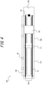
- FIG. 4 is a schematic diagram illustrating the arrangement of relay devices according to an embodiment of the present disclosure.
- a coal tower 108 is located at one end of the coke oven 100, and an intermediate deck 111 is located between a coke oven battery 109 closer to the coal tower 108 and a coke oven battery 110 farther from the coal tower 108.
- Coal charging vehicle rail girders (not illustrated) and coal charging vehicle rails 103 laid on the coal charging vehicle rail girders are installed on the coke oven 100.
- a coal charging vehicle 107 for charging coal into each combustion chamber runs on the coal charging vehicle rails 103.
- thermoelectric-wireless transmission unit 10 corresponding to each sensor is attached as illustrated in FIG. 2 .
- a plurality of relay devices 30 are installed on the oven top deck 106, and a reception device 40 is installed near the coal tower 108 at the end of the coke oven 100.
- relay devices 30 are also installed on the coal charging vehicle 107 as a moving obstacle as described below.
- FIG. 5 is a schematic diagram illustrating the installation state of relay devices on the coal charging vehicle 107 according to an embodiment of the present disclosure.
- a thermoelectric-wireless transmission unit 10 is installed on each of a pair of coal charging vehicle rail girders 104 installed on the upper surface of the coke oven 100.
- Relay devices 30 are installed on the coal charging vehicle 107 running on the coal charging vehicle rails 103. It is preferable that each relay device 30 installed on the coal charging vehicle 107 is located on the same side of the coal charging vehicle rail 103 as the wireless transmission device.
- the thermoelectric-wireless transmission unit 10 is located inside the coal charging vehicle rail 103.
- the relay device 30 installed on the coal charging vehicle 107 is also located inside the wheel 112 of the coal charging vehicle 107 so as to be close to the thermoelectric-wireless transmission unit 10.
- the relay device 30 installed on the coal charging vehicle 107 is also located outside the wheel 112 of the coal charging vehicle 107.
- the relay device may be integrated with an antenna for transmission and reception, but it is also preferable to use a relay device whose body portion and antenna portion can be installed separately from each other via a cable or the like.
- the antenna may be installed at the position of 30 in FIG. 5
- the body of the relay device may be installed at another position of the coal charging vehicle 107.
Landscapes
- Engineering & Computer Science (AREA)
- Chemical & Material Sciences (AREA)
- Computer Networks & Wireless Communication (AREA)
- Physics & Mathematics (AREA)
- General Physics & Mathematics (AREA)
- Mechanical Engineering (AREA)
- General Engineering & Computer Science (AREA)
- Materials Engineering (AREA)
- Oil, Petroleum & Natural Gas (AREA)
- Organic Chemistry (AREA)
- Arrangements For Transmission Of Measured Signals (AREA)
- Waste-Gas Treatment And Other Accessory Devices For Furnaces (AREA)
Abstract
Description
- The present disclosure relates to a measurement system for steelworks equipment, a coke oven, and a coke production method.
- In production equipment of various factories such as steelworks, sensors are used for measurement for various purposes such as operation status check, abnormality detection, and equipment maintenance. Wireless transmission of signals output from sensors is also performed in recent years. Wireless signal transmission is advantageous in that it increases the degree of freedom in sensor installation because there is no need to lay cables for signal transmission.
- However, it is still necessary to supply power to the sensors themselves and devices for wireless transmission. For example, in the case of wired power supply, cables for power supply are needed, which reduces the foregoing advantage of using wireless transmission. Power supply using batteries eliminates the need for cables, but requires maintenance work such as battery replacement.
- In view of this, techniques are proposed that allow sensors for wirelessly transmitting signals (hereafter also referred to as "wireless sensors") to have a power generation function to enable stand-alone power supply for a long period of time.
- For example,
JP 2013-122718 A -
JP 2016-157356 A -
JP 2018-200518 A -
- PTL 1:
JP 2013-122718 A - PTL 2:
JP 2016-157356 A - PTL 3:
JP 2018-200518 A - In each of the wireless sensors proposed in PTL 1 to PTL 3, a sensor can be supplied with power from a power generation device mounted integrally with the sensor. This eliminates the need for installation of power supply cables and maintenance work such as battery replacement.
- Particularly in steelworks equipment, the object to be measured tends to be a very wide range, and the environment is usually harsh, such as high temperatures. Eliminating the need for installation of power supply cables and maintenance work such as battery replacement is therefore very advantageous.
- However, the wireless sensor proposed in PTL 1 uses a vibration power generation element as a power source, and thus can only be used in locations where a certain amount of vibration occurs constantly.
- The wireless sensor proposed in PTL 2 uses a solar cell as a power source, and thus can only be used in environments and time periods in which sufficient light is incident. To solve this problem, PTL 2 proposes to provide a power storage that stores the power generated by the solar cell module. However, a large power storage is required in order to stably continue operation even in environments in which light is not incident, such as at night. This causes an increase of the size of the wireless sensor.
- PTL 3 describes the use of thermoelectric power generation, but does not reveal specifically how thermoelectric power generation is applied to steelworks equipment.
- It could therefore be helpful to provide a measurement system for steelworks equipment that can operate with stand-alone power supply in various equipment of steelworks where wiring and maintenance are difficult and can reliably monitor measurement results at a position away from the installation location of a sensor. It could also be helpful to provide a coke oven and a coke production method using the measurement system for steelworks equipment.
- In view of the above, we provide the following.
- 1. A measurement system for steelworks equipment, comprising: a thermoelectric power generation device; a sensor; a conversion device configured to convert a signal output from the sensor into a signal that is wirelessly transmittable; a wireless transmission device configured to wirelessly transmit the signal converted by the conversion device; a relay device configured to relay the signal transmitted from the wireless transmission device; and a reception device configured to receive one or both of the signal transmitted from the wireless transmission device and the signal relayed by the relay device, wherein the conversion device and the wireless transmission device are driven by power generated by the thermoelectric power generation device.
- 2. The measurement system for steelworks equipment according to 1., wherein more relay devices are located in a part where an obstacle stays for a longer time than in a part where the obstacle stays for a shorter time.
- 3. The measurement system for steelworks equipment according to 1. or 2., wherein at least one relay device is installed on a moving obstacle.
- 4. The measurement system for steelworks equipment according to any one of 1. to 3., wherein the sensor is a temperature sensor.
- 5. A coke oven comprising the measurement system for steelworks equipment according to any one of 1. to 4.
- 6. A coke production method of producing coke using a coke oven, the coke production method comprising measuring a temperature of the coke oven using the measurement system for steelworks equipment according to any one of 1. to 4.
- It is thus possible to provide a measurement system for steelworks equipment that can operate with stand-alone power supply in various equipment of steelworks where wiring and maintenance are difficult and can reliably monitor measurement results at a position away from the installation location of a sensor. The measurement system for steelworks equipment is suitable for use in various production equipment such as coke ovens.
- In the accompanying drawings:
-
FIG. 1 is a schematic diagram illustrating an example of the structure of a coke oven; -
FIG. 2 is a schematic diagram illustrating a measurement system for steelworks equipment according to an embodiment of the present disclosure; -
FIG. 3 is a schematic diagram illustrating the arrangement of relay devices according to an embodiment of the present disclosure; -
FIG. 4 is a schematic diagram illustrating the arrangement of relay devices according to an embodiment of the present disclosure; and -
FIG. 5 is a schematic diagram illustrating the installation state of relay devices on a coal charging vehicle according to an embodiment of the present disclosure. - A measurement system according to Embodiment 1 of the present disclosure will be described below. In the following description, the "measurement system for steelworks equipment" is also simply referred to as the "measurement system".
- The measurement system according to Embodiment 1 of the present disclosure includes the following components (1) to (6):
- (1) a thermoelectric power generation device;
- (2) a sensor;
- (3) a conversion device that converts a signal output from the sensor into a wirelessly transmittable signal;
- (4) a wireless transmission device that wirelessly transmits the signal converted by the conversion device;
- (5) a relay device that relays the signal transmitted from the wireless transmission device; and
- (6) a reception device that receives one or both of the signal transmitted from the wireless transmission device and the signal relayed by the relay device.
- The conversion device (3) and the wireless transmission device (4) are driven by power generated by the thermoelectric power generation device (1).
- Each component in the measurement system will be described below.
- The thermoelectric power generation device is a device capable of generating power by utilizing the temperature difference between one side (high temperature side) and the other side (low temperature side) of the thermoelectric power generation device. The thermoelectric power generation device typically includes a thermoelectric element that combines a p-type semiconductor and an n-type semiconductor.
- The thermoelectric power generation device is not limited, and any thermoelectric power generation device may be used. The use of the thermoelectric power generation device makes it possible to generate power using heat from various equipment in a steelworks and drive the conversion device and the wireless transmission device using the generated power.
- The heat source for generating power in the thermoelectric power generation device is not limited, and any heat source may be used. It is preferable to use a high temperature part of the steelworks equipment as the heat source. That is, it is preferable to directly or indirectly install the high temperature side of the thermoelectric power generation device in the high temperature part of the steelworks equipment. The thermoelectric power generation device preferably includes a heat receiving sheet on the high temperature side, from the viewpoint of enhancing the utilization efficiency of heat from the heat source. As the heat receiving sheet, for example, a metallic sheet or a ceramic sheet may be used.
- The thermoelectric power generation device preferably includes a cooling means on the low temperature side, from the viewpoint of enhancing the power generation efficiency. As the cooling means, for example, one or both of a heat radiating member such as heat radiating fins and a heat exchanger that performs cooling by exchanging heat with a cooling medium such as water or oil may be used.
- The sensor is not limited, and any sensor may be used depending on the object to be measured. As the sensor, for example, at least one selected from the group consisting of a temperature sensor, a pressure sensor, a flow sensor, a vibration sensor, and an acceleration sensor may be used. Examples of the temperature sensor include a thermocouple, a resistance temperature detector, and a thermistor.
- The number of sensors is not limited, and may be any number of 1 or 2 or more. It is preferable to arrange a plurality of sensors at different points, from the viewpoint of obtaining information about the distribution of measured values. A plurality of sensors may be arranged at the same point, from the viewpoint of redundancy and accuracy improvement. From the viewpoint of measuring the distribution of measured values in more detail, a larger number of sensors is better, and accordingly no upper limit is placed on the number of sensors. Since the cost increases with the increase of the number of sensors, however, the number of sensors is preferably 1000 or less from the viewpoint of cost effectiveness.
- The conversion device converts a signal output from the sensor into a wirelessly transmittable signal. The conversion device is not limited, and any device such as a commercially available converter may be used.
- The wireless transmission device wirelessly transmits the signal converted by the conversion device. The wireless transmission device is not limited, and any device capable of signal transmission, such as a commercially available device, may be used.
- The number of thermoelectric power generation devices, the number of sensors, the number of conversion devices, and the number of wireless transmission devices included in the measurement system for steelworks equipment according to the present disclosure may be the same or different. For example, one thermoelectric power generation device may supply power to a plurality of conversion devices and a plurality of wireless transmission devices. Signals output from a plurality of sensors may be collectively transmitted by one conversion device and one wireless transmission device.
- It is also preferable to mount the thermoelectric power generation device, the conversion device, and the wireless transmission device in one package. Mounting these components in one package facilitates handling, and also facilitates installation of a heat radiating member and a light shielding member as described later. In the following description, one package in which the thermoelectric power generation device, the conversion device, and the wireless transmission device are mounted is referred to as a "thermoelectric-wireless transmission unit" for the sake of convenience.
- The measurement system for steelworks equipment according to the present disclosure preferably includes a heat radiating member for cooling one or both of the conversion device and the wireless transmission device. Steelworks equipment is often at high temperatures, as mentioned above. The use of the heat radiating member can suppress the temperature rise of the conversion device and the wireless transmission device. As the heat radiating member, for example, heat radiating fins and the like may be used.
- The heat radiating member can also serve as cooling means on the low temperature side of the thermoelectric power generation device. For example, in the case where the thermoelectric power generation device, the conversion device, and the wireless transmission device are mounted in one package (thermoelectric-wireless transmission unit), it is possible to cool the thermoelectric power generation device, the conversion device, and the wireless transmission device by providing the heat radiating member in the thermoelectric-wireless transmission unit.
- The measurement system for steelworks equipment according to the present disclosure preferably includes a light shielding member for blocking direct sunlight. For example, in the case where the measurement system is installed outdoors, such as above a coke oven, direct sunlight can cause the device temperature to rise. Such temperature rise can be suppressed by blocking sunlight using the light shielding member. The light shielding member is preferably configured to block direct sunlight to at least one of the thermoelectric power generation device, the conversion device, and the wireless transmission device. For example, in the case where the thermoelectric power generation device, the conversion device, and the wireless transmission device are mounted in one package (thermoelectric-wireless transmission unit), it is possible to suppress the temperature rise of the thermoelectric power generation device, the conversion device, and the wireless transmission device by providing the light shielding member in the thermoelectric-wireless transmission unit.
- The measurement system for steelworks equipment according to the present disclosure preferably includes both the heat radiating member and the light shielding member, from the viewpoint of preventing the temperature rise more effectively. In such a case, the light shielding member is preferably installed above the heat radiating member. This prevents the heat radiating member from being exposed to direct sunlight, and consequently enables the heat radiating member to function more effectively.
- The measurement system according to the present disclosure further includes the relay device that relays the signal transmitted from the wireless transmission device. Thus, the signal can be stably received even at a position away from the location where the sensor is installed. The relay means is not limited, and any means capable of relaying the signal transmitted from the wireless transmission device may be used.
- The number of relay devices is not limited, and any number of relay devices, i.e. one or two or more relay devices, may be used. In the case where the distance between the sensor and the reception device is long or in the case where the condition of radio waves, etc. used for wireless transmission is poor, it is preferable to use a plurality of relay devices.
- The reception device receives the signal relayed by the relay device. Although the signal transmitted from the wireless transmission device is basically relayed by the relay device, it is not always necessary to relay the signal by the relay device. For example, a signal from the wireless transmission device installed at a position near the reception device can be directly received by the reception device without via the relay device. The reception device is thus configured to receive one or both of the signal transmitted from the wireless transmission device and the signal relayed by the relay device. The reception device is not limited, and any device capable of signal reception, such as a commercially available reception device, may be used.
- In the measurement system according to the present disclosure, the conversion device and the wireless transmission device are driven by the power generated by the thermoelectric power generation device. This eliminates the need for wiring, batteries, and the like for supplying power to the conversion device and the wireless transmission device. The measurement system according to the present disclosure can thus be easily installed and operated even in a location where wiring and maintenance such as battery replacement are difficult.
- The measurement system according to the present disclosure preferably further includes a capacitor for temporarily storing the power generated by the thermoelectric power generation device.
- The application of the measurement system to a coke oven will be described in detail below.
- In the case of applying the measurement system to a coke oven, the sensor is preferably used to measure the temperature of a combustion chamber. Since the temperature of the coke oven, particularly the combustion chamber, is considerably high, a thermocouple is preferably used as the sensor.
- Signal transmission may be performed at any interval. For example, the power generated by the thermoelectric power generation device may be temporarily stored in the capacitor, and a signal may be transmitted when the stored power exceeds a certain amount. In this case, the transmission interval depends on the temperature of the heat source. It is therefore desirable to adjust the installation position of the thermoelectric power generation device so that the transmission interval will not be excessively long. The transmission interval is preferably 600 s or less, and more preferably 60 s or less. If the transmission interval is excessively short, the power consumption is excessively high. Accordingly, the transmission interval is preferably 0.1 s or more, and more preferably 1 s or more.
- Each device included in the measurement system according to the present disclosure is preferably installed at a position where the temperature during operation does not exceed the heat resistant temperature of the device, because the oven top temperature is considerably high during operation of the coke oven. In particular, electronic devices such as the conversion device and the wireless transmission device are preferably installed at positions where the temperature is 80 °C or less. For example, the oven top temperature of the coke oven during operation is measured beforehand, and the electronic devices are installed at positions where the temperature is 80 °C or less. The electronic devices such as the conversion device and the wireless transmission device are preferably installed at positions where the temperature is 0 °C or more.
- In the case where the wireless transmission device is installed on top of a typical oven, the distance from the wireless transmission device to the location where the temperature of the coke oven is managed (e.g. control room) is at least several tens of meters. Moreover, on top of the coke oven, a coal charging vehicle for charging coal into the coke oven, etc. travel, and there are many obstacles that interfere with wireless communication. The use of the relay device enables stable signal transmission and reception even in such an environment. The number of relay devices is preferably 2 or more and more preferably 3 or more, from the viewpoint of stability of transmission and reception. If the number of relay devices is excessively large, the effect is saturated, and the cost increases. The number of relay devices is therefore preferably 10 or less, and more preferably 5 or less. The number of relay devices is further preferably 4, from the viewpoint of the balance between cost and stability.
- A deck for maintenance and inspection is provided on top of a typical coke oven. Accordingly, the relay device is preferably installed on the deck.
- The reception device can be installed at any position. The reception device may be installed at a position away from the coke oven, such as the location where the temperature of the coke oven is managed (e.g. control room). The reception device may be installed at a position closer to the coke oven, such as the deck on top of the coke oven, from the viewpoint of enabling stable reception while reducing the number of relay devices required.
- With a coke production method according to an embodiment of the present disclosure, the temperature of the coke oven, for example, the temperature of the combustion chamber, can be measured using the measurement system described above. By controlling the combustion state of the coke oven based on the measured temperature, coke with stable quality can be produced.
- The method of controlling the combustion state is not limited, and any method, such as adjusting the amount of fuel supplied to the combustion chamber, may be used. The adjustment of the combustion state is preferably performed for each combustion chamber. For example, a target temperature is determined for each combustion chamber beforehand, and the combustion state of the combustion chamber is adjusted based on the difference between the measured temperature of the combustion chamber and the target temperature. The method of determining the target temperature is not limited, and may be any method including various known methods. For example, the time required for coking (actual coking time) is obtained from actual operation results for each carbonization chamber included in the coke oven, and the target temperature is determined from the difference from the target coking time.
- In an actual coke oven, a plurality of carbonization chambers and a plurality of combustion chambers are alternately arranged continuously, as illustrated in
FIG. 1 . Hence, coking in a carbonization chamber is influenced by the temperatures of a plurality of combustion chambers adjacent to the carbonization chamber. It is therefore preferable to determine the target temperature of each combustion chamber based on the influence of the temperature of the combustion chamber on the plurality of carbonization chambers. - The foregoing control may be performed based on a database obtained by collecting, using the measurement system for steelworks equipment according to the present disclosure, the relationship between the temperature of each combustion chamber and the time actually required for coking (coking time). The use of such a database enables control in consideration of the different characteristics of each kiln. Herein, the term "coking time" refers to the time from when coal is charged into the carbonization chamber to when the coal is carbonized and turned into coke.
- An example of an embodiment in this specification will be described in more detail below, with reference to the drawings. In the following description, too, the application of the measurement system to a coke oven will be described.
-
FIG. 1 is a schematic diagram illustrating an example of the structure of a coke oven. Acoke oven 100 has a structure in which carbonizationchambers 101 for storing and carbonizing coal andcombustion chambers 102 for supplying heat to thecarbonization chambers 101 are alternately arranged in the oven width direction. Heat is supplied from acombustion chamber 102 to acarbonization chamber 101 through a refractory separating the carbonization chamber and the combustion chamber. A typical coke oven in a steelworks includes at least several tens of carbonization chambers, and its length L in the oven width direction is several hundred meters. The size of each of thecarbonization chamber 101 and thecombustion chamber 102 is, for example, about 7 m in height H and about 16 m in depth D. - In a typical coke oven, a pair of a carbonization chamber and a combustion chamber adjacent to each other is called "one kiln" or "one gate", and a block of about 50 kilns is called a "coke oven battery". Coal charging vehicle rails 103 are laid on top of the coke oven, and a
coal charging vehicle 107 for charging coal into eachcarbonization chamber 101 runs on the coal charging vehicle rails 103. Acoal tower 108 for supplying coal to thecoal charging vehicle 107 is located between or at the end of a plurality of coke oven batteries. - In such a coke oven including many combustion chambers, temperature measurement is necessary in order to control the temperature of each combustion chamber. Hence, a sensor (thermocouple) is installed in each combustion chamber, and the temperature is measured by the measurement system according to the present disclosure.
-
FIG. 2 is a schematic diagram illustrating a measurement system 1 for steelworks equipment (hereinafter "measurement system 1") according to an embodiment of the present disclosure. The measurement system 1 includes a thermoelectric-wireless transmission unit 10 in which a thermoelectric power generation device, a conversion device, and a wireless transmission device are mounted in one package, athermocouple 20 as a sensor, and arelay device 30. - The measurement system 1 is installed on top of the
coke oven 100, i.e. on or above thecoke oven 100. Here, since the temperature on top of thecoke oven 100 is high, if the devices are installed directly on the oven, the devices may be damaged. Moreover, the coal charging vehicle rails 103 are laid on top of the coke oven, and thecoal charging vehicle 107 for charging coal into eachcarbonization chamber 101 runs on the coal charging vehicle rails 103, as mentioned above. It is therefore necessary to install the devices so as not to interfere with the running of thecoal charging vehicle 107. In this embodiment, the thermoelectric-wireless transmission unit 10 is installed on coal chargingvehicle rail girders 104 laid as a support member for laying the coal charging vehicle rails 103. -
Heat radiating fins 11 and alight shielding member 12 for blocking direct sunlight are provided on the upper surface of the thermoelectric-wireless transmission unit 10. Thus, the temperature rise of the thermoelectric-wireless transmission unit 10 can be suppressed. Theheat radiating fins 11 also serve to cool the low temperature side of the thermoelectric power generation device included in the thermoelectric-wireless transmission unit 10. - The
thermocouple 20 is inserted inside thecombustion chamber 102 through aninspection hole 105 provided in the upper part of thecombustion chamber 102. Thethermocouple 20 is connected to the conversion device in the thermoelectric-wireless transmission unit 10, and the temperature measured by thethermocouple 20 is transmitted by the wireless transmission device in the thermoelectric-wireless transmission unit 10. - An oven
top deck 106, which is a corridor for performing equipment maintenance and inspection, etc., is installed on top of thecoke oven 100. In this embodiment, therelay device 30 is installed on the oventop deck 106. InFIG. 2 , the parts are illustrated at different scales for the sake of convenience. In an actual coke oven, an oven top deck is located at a height of about 8 m above the oven. Therefore, therelay device 30 can receive wireless signals from a wide range without being affected by the heat of the coke oven. - Although the installation state of one
thermocouple 20 is illustrated inFIG. 2 , theactual coke oven 100 includesmany combustion chambers 102 as illustrated inFIG. 1 . Hence, it is preferable to install at least one sensor per combustion chamber, in order to monitor the temperature of eachcombustion chamber 102. In this case, one thermoelectric-wireless transmission unit may be used for one sensor. Alternatively, one thermoelectric-wireless transmission unit may process signals from a plurality of sensors. - It is more preferable to install two or more sensors per combustion chamber, from the viewpoint of measuring the temperature in the combustion chamber more accurately. In the case of installing a plurality of sensors in one combustion chamber, it is preferable to space the plurality of sensors apart in the depth direction of the combustion chamber (the direction of arrow D in
FIG. 1 ). - Meanwhile, since one relay device can relay signals from a plurality of wireless transmission devices, there is no need to use the same number of relay devices as the wireless transmission devices (thermoelectric-wireless transmission units). Therefore, the number of relay devices included in the measurement system is preferably less than the number of wireless transmission devices, more preferably less than or equal to 1/2 of the number of wireless transmission devices, and further preferably less than or equal to 1/5 of the number of wireless transmission devices. The number of relay devices included in the measurement system is even more preferably less than or equal to 1/10 of the number of wireless transmission devices, from the viewpoint of cost effectiveness.
- For example, in the case of a coke oven including 65 combustion chambers, two sensors and thermoelectric-wireless transmission units per combustion chamber, a total of 130 sensors and thermoelectric-wireless transmission units, are arranged, and four relay devices are used to relay radio waves. Meanwhile, one reception device is installed at the end of the coke oven. The reception device may be installed in, for example, a control room for controlling the coke oven.
- The measurement system according to the present disclosure may be additionally introduced into a coke oven that already includes temperature measurement means and a temperature management system. In such a case, the existing temperature management system may be used to perform temperature management based on the temperature measured by the measurement system according to the present disclosure. Here, there is a possibility that the temperature measured by the existing temperature measurement means and the temperature measured by the measurement system according to the present disclosure do not match. In view of this, the relationship between the temperature measured by the existing temperature measurement means and the temperature measured by the measurement system according to the present disclosure may be determined beforehand. Then, the temperature measured by the measurement system according to the present disclosure may be converted into the temperature measured by the existing temperature measurement means based on the relationship, and temperature management may be performed based on the converted temperature.
- Although the above describes an example of measuring the temperature in the combustion chamber of the coke oven, the present disclosure is not limited to such, and any element in any equipment in steelworks may be subjected to measurement.
- A measurement system according to Embodiment 2 of the present disclosure will be described below. The description of the same parts as those in Embodiment 1 is omitted here.
- The measurement system according to Embodiment 2 of the present disclosure has the same structure as the measurement system according to Embodiment 1. In addition, more relay devices are located in a part where an obstacle stays for a longer time than in a part where the obstacle stays for a shorter time.
- As described in Embodiment 1 above, the use of the relay device makes it possible to reliably monitor the measurement results even at a position away from the installation location of the sensor. However, since various large-sized mobile devices are used in steelworks equipment, there is a possibility that such devices interfere with wireless communication and hinder signal relay by the relay device. For example, in the case of a coke oven, rails are laid on top of the coke oven, and a coal charging vehicle for charging coal as raw material into each carbonization chamber of the coke oven runs on the rails. The presence of a large device such as a coal charging vehicle interferes with wireless communication. By arranging the number (density) of relay devices corresponding to the staying time of such a moving obstacle, the influence of the obstacle can be reduced and measurement data can be received more stably.
- Herein, the "part where an obstacle stays for a longer time" refers to an area where an obstacle such as a coal charging vehicle stays for a longer time, and the "part where the obstacle stays for a shorter time" refers to an area where the obstacle stays for a shorter time than in the part where the obstacle stays for a longer time. For example, the entire area in which the relay devices are installed is divided into a plurality of sections, and the number of relay devices to be installed in each section is determined depending on the staying time of the obstacle in the section.
- The number (total number) of relay devices is not limited, and may be any number as long as they are arranged in the foregoing manner. Usually, the number (a plurality) of relay devices depending on the distance between the sensor and the reception device, the state of radio waves, and the like are used.
- The application of the measurement system according to Embodiment 2 to a coke oven will be described in detail below.
- A coke oven typically includes many combustion chambers, as illustrated in
FIG. 1 . For example, in the case of a coke oven (coke oven battery) including 65 combustion chambers, two sensors and thermoelectric-wireless transmission units per combustion chamber, a total of 130 sensors and thermoelectric-wireless transmission units, are arranged, and two to five relay devices are used to relay radio waves. Meanwhile, one reception device is installed at the end of the coke oven. The reception device may be installed in, for example, a control room for controlling the coke oven. An example of the arrangement of relay devices will be described in detail below, with reference toFIG. 3 . -
FIG. 3 is a schematic diagram illustrating the arrangement of relay devices according to an embodiment of the present disclosure. Acoal tower 108 is located at one end of acoke oven 100, and anintermediate deck 111 is located between acoke oven battery 109 closer to thecoal tower 108 and acoke oven battery 110 farther from thecoal tower 108. Coal charging vehicle rail girders (not illustrated) and coal charging vehicle rails 103 laid on the coal charging vehicle rail girders are installed on thecoke oven 100. - Two sensors are installed in each combustion chamber in the
coke oven 100, and a thermoelectric-wireless transmission unit 10 corresponding to each sensor is attached as illustrated inFIG. 2 . A plurality ofrelay devices 30 are installed on an oventop deck 106, and areception device 40 is installed near thecoal tower 108 at the end of thecoke oven 100. - A coal charging vehicle runs on the coal charging vehicle rails 103 and charges coal into each combustion chamber. Usually, the time during which the coal charging vehicle stays on the
coke oven battery 110 farther from thecoal tower 108 is shorter than the time during which the coal charging vehicle stays on thecoke oven battery 109 closer to thecoal tower 108. Accordingly, the number (N1) ofrelay devices 30 installed on thecoke oven battery 109 is made larger than the number (N2) ofrelay devices 30 installed on thecoke oven battery 110. N2 is preferably 1 to 2. N1 is preferably 2 to 4 and larger than N2. For example, inFIG. 3 , the number ofrelay devices 30 installed on thecoke oven battery 109 is 3, and the number ofrelay devices 30 installed on thecoke oven battery 110 is 2. - In other words, in this example, a plurality of relay devices are installed on the coke oven made up of a plurality of coke oven batteries so as to be spaced apart in the oven width direction of the coke oven (the direction of arrow L in
FIG. 1 ), and the relay device arrangement density is higher for a coke oven battery closer to the coal tower. - Although the above describes an example in which the number of relay devices installed is set for each coke oven battery, the unit of region for which the number of relay devices installed is set is not limited to such, and any unit of region may be selected.
- Although the above describes an example of measuring the temperature in the combustion chamber of the coke oven, the present disclosure is not limited to such, and any element in any equipment in steelworks may be subjected to measurement.
- A measurement system according to Embodiment 3 of the present disclosure will be described below. The description of the same parts as those in Embodiments 1 and 2 is omitted here.
- The measurement system according to Embodiment 3 of the present disclosure has the same structure as the measurement system according to Embodiment 1 or 2. In addition, at least one relay device is installed on a moving obstacle.
- As described in Embodiment 1 above, the use of the relay device makes it possible to reliably monitor the measurement results even at a position away from the installation location of the sensor. However, since various large-sized mobile devices are used in steelworks equipment, there is a possibility that such devices interfere with wireless communication and hinder signal relay by the relay device. For example, in the case of a coke oven, rails are laid on top of the coke oven, and a coal charging vehicle for charging coal as raw material into each carbonization chamber of the coke oven runs on the rails. The presence of a large device such as a coal charging vehicle interferes with wireless communication. By installing at least one relay device on such a moving obstacle itself, measurement data can be received stably without being interfered by the obstacle.
- The relay devices other than the relay device installed on the obstacle may be installed at any positions without limitation, but are normally installed at locations that do not move.
- The application of the measurement system according to Embodiment 3 to a coke oven will be described in detail below.
- An oven
top deck 106, which is a corridor for performing equipment maintenance and inspection, etc., is installed on top of thecoke oven 100, as illustrated inFIG. 2 . In an embodiment of the present disclosure, part of therelay devices 30 can be installed on the oventop deck 106. In an actual coke oven, an oven top deck is located at a height of about 8 m above the oven. Therefore, therelay device 30 can receive wireless signals from a wide range without being affected by the heat of the coke oven. In this embodiment, the other relay device (or devices) is installed on a moving obstacle such as a coal charging vehicle. - An example of the arrangement of relay devices will be described in detail below, with reference to
FIGS. 4 and5 . -
FIG. 4 is a schematic diagram illustrating the arrangement of relay devices according to an embodiment of the present disclosure. Acoal tower 108 is located at one end of thecoke oven 100, and anintermediate deck 111 is located between acoke oven battery 109 closer to thecoal tower 108 and acoke oven battery 110 farther from thecoal tower 108. Coal charging vehicle rail girders (not illustrated) and coal charging vehicle rails 103 laid on the coal charging vehicle rail girders are installed on thecoke oven 100. Acoal charging vehicle 107 for charging coal into each combustion chamber runs on the coal charging vehicle rails 103. - Two sensors are installed in each combustion chamber in the
coke oven 100, and a thermoelectric-wireless transmission unit 10 corresponding to each sensor is attached as illustrated inFIG. 2 . A plurality ofrelay devices 30 are installed on the oventop deck 106, and areception device 40 is installed near thecoal tower 108 at the end of thecoke oven 100. In this embodiment,relay devices 30 are also installed on thecoal charging vehicle 107 as a moving obstacle as described below. -
FIG. 5 is a schematic diagram illustrating the installation state of relay devices on thecoal charging vehicle 107 according to an embodiment of the present disclosure. A thermoelectric-wireless transmission unit 10 is installed on each of a pair of coal chargingvehicle rail girders 104 installed on the upper surface of thecoke oven 100.Relay devices 30 are installed on thecoal charging vehicle 107 running on the coal charging vehicle rails 103. It is preferable that eachrelay device 30 installed on thecoal charging vehicle 107 is located on the same side of the coal chargingvehicle rail 103 as the wireless transmission device. In the example illustrated inFIG. 5 , the thermoelectric-wireless transmission unit 10 is located inside the coal chargingvehicle rail 103. Hence, therelay device 30 installed on thecoal charging vehicle 107 is also located inside thewheel 112 of thecoal charging vehicle 107 so as to be close to the thermoelectric-wireless transmission unit 10. In the case where the thermoelectric-wireless transmission unit 10 is located outside the coal chargingvehicle rail 103, therelay device 30 installed on thecoal charging vehicle 107 is also located outside thewheel 112 of thecoal charging vehicle 107. - The relay device may be integrated with an antenna for transmission and reception, but it is also preferable to use a relay device whose body portion and antenna portion can be installed separately from each other via a cable or the like. For example, the antenna may be installed at the position of 30 in
FIG. 5 , and the body of the relay device may be installed at another position of thecoal charging vehicle 107. - Although the above describes an example of measuring the temperature in the combustion chamber of the coke oven, the present disclosure is not limited to such, and any element in any equipment in steelworks may be subjected to measurement.
-
- 1
- measurement system for steelworks equipment
- 10
- thermoelectric-wireless transmission unit
- 11
- heat radiating fin
- 12
- light shielding member
- 20
- thermocouple
- 30
- relay device
- 40
- reception device
- 100
- coke oven
- 101
- carbonization chamber
- 102
- combustion chamber
- 103
- coal charging vehicle rail
- 104
- coal charging vehicle rail girder
- 105
- inspection hole
- 106
- oven top deck
- 107
- coal charging vehicle
- 108
- coal tower
- 109
- coke oven battery
- 110
- coke oven battery
- 111
- intermediate deck
- 112
- wheel
Claims (6)
- A measurement system for steelworks equipment, comprising:a thermoelectric power generation device;a sensor;a conversion device configured to convert a signal output from the sensor into a signal that is wirelessly transmittable;a wireless transmission device configured to wirelessly transmit the signal converted by the conversion device;a relay device configured to relay the signal transmitted from the wireless transmission device; anda reception device configured to receive one or both of the signal transmitted from the wireless transmission device and the signal relayed by the relay device,wherein the conversion device and the wireless transmission device are driven by power generated by the thermoelectric power generation device.
- The measurement system for steelworks equipment according to claim 1, wherein more relay devices are located in a part where an obstacle stays for a longer time than in a part where the obstacle stays for a shorter time.
- The measurement system for steelworks equipment according to claim 1 or 2, wherein at least one relay device is installed on a moving obstacle.
- The measurement system for steelworks equipment according to any one of claims 1 to 3, wherein the sensor is a temperature sensor.
- A coke oven comprising
the measurement system for steelworks equipment according to any one of claims 1 to 4. - A coke production method of producing coke using a coke oven, the coke production method comprising
measuring a temperature of the coke oven using the measurement system for steelworks equipment according to any one of claims 1 to 4.
Applications Claiming Priority (4)
| Application Number | Priority Date | Filing Date | Title |
|---|---|---|---|
| JP2021019763 | 2021-02-10 | ||
| JP2021019766 | 2021-02-10 | ||
| JP2021019761 | 2021-02-10 | ||
| PCT/JP2022/003403 WO2022172789A1 (en) | 2021-02-10 | 2022-01-28 | Steel plant facility measurement system, coke oven, and coke production method |
Publications (2)
| Publication Number | Publication Date |
|---|---|
| EP4276159A1 true EP4276159A1 (en) | 2023-11-15 |
| EP4276159A4 EP4276159A4 (en) | 2024-07-10 |
Family
ID=82838806
Family Applications (1)
| Application Number | Title | Priority Date | Filing Date |
|---|---|---|---|
| EP22752618.3A Pending EP4276159A4 (en) | 2021-02-10 | 2022-01-28 | Steel plant facility measurement system, coke oven, and coke production method |
Country Status (4)
| Country | Link |
|---|---|
| EP (1) | EP4276159A4 (en) |
| JP (2) | JP7276604B2 (en) |
| KR (1) | KR102759410B1 (en) |
| WO (1) | WO2022172789A1 (en) |
Family Cites Families (22)
| Publication number | Priority date | Publication date | Assignee | Title |
|---|---|---|---|---|
| JPS58134177A (en) * | 1982-02-02 | 1983-08-10 | Nippon Steel Corp | Method for controlling combustion temperature distribution in coke oven |
| JP2006099255A (en) * | 2004-09-28 | 2006-04-13 | Mitsui Eng & Shipbuild Co Ltd | Material management system |
| JP5750822B2 (en) * | 2008-11-21 | 2015-07-22 | Jfeスチール株式会社 | Coke oven combustion chamber temperature measurement device and temperature management system |
| US8833052B2 (en) * | 2009-11-30 | 2014-09-16 | General Electric Company | Systems and methods for controlling fuel mixing |
| CN102297723B (en) * | 2011-05-20 | 2012-12-26 | 袁国炳 | Online optical fiber infrared temperature measuring equipment suitable for high temperature environment |
| US20130005372A1 (en) * | 2011-06-29 | 2013-01-03 | Rosemount Inc. | Integral thermoelectric generator for wireless devices |
| TWI439336B (en) * | 2011-07-13 | 2014-06-01 | China Steel Corp | Wireless temperature measurement system and its temperature measurement method for power supply of Sheng iron (steel) bucket |
| JP2013122718A (en) | 2011-12-12 | 2013-06-20 | Ngk Spark Plug Co Ltd | Radio sensor node |
| KR101686034B1 (en) * | 2012-09-27 | 2016-12-13 | 제이에프이 스틸 가부시키가이샤 | Manufacturing facility line and thermoelectric power generation method |
| JP5751261B2 (en) * | 2013-01-17 | 2015-07-22 | ヤマハ株式会社 | Thermoelectric power generation unit |
| JP6048368B2 (en) * | 2013-10-22 | 2016-12-21 | Jfeスチール株式会社 | Radiation thermometer calibration device and calibration method |
| WO2016006089A1 (en) * | 2014-07-10 | 2016-01-14 | 富士通株式会社 | Heat dissipation component, heat dissipation component manufacturing method, electronic device, electronic device manufacturing method, integrated module, and information processing system |
| JP6400498B2 (en) * | 2015-02-06 | 2018-10-03 | リンテック株式会社 | Wireless tag and RFID system |
| JP6433335B2 (en) | 2015-02-26 | 2018-12-05 | 一般財団法人マイクロマシンセンター | Wireless sensor terminal |
| JP2017041309A (en) * | 2015-08-17 | 2017-02-23 | 三菱日立パワーシステムズ株式会社 | Power generating system and operating method therefor |
| CN106753445A (en) * | 2017-01-23 | 2017-05-31 | 中冶焦耐(大连)工程技术有限公司 | A coke oven bridge tube temperature wireless acquisition system |
| JP6767928B2 (en) | 2017-05-26 | 2020-10-14 | 株式会社Kelk | Thermoelectric transmitter |
| JP6891909B2 (en) * | 2018-04-03 | 2021-06-18 | Jfeスチール株式会社 | Data transmission equipment and methods in the raw material yard, as well as conveyor belt management systems and methods |
| CN208883786U (en) * | 2018-07-18 | 2019-05-21 | 辽宁工程技术大学 | A coke oven gas collecting pipe pressure data measuring device |
| JP2020137403A (en) * | 2019-02-15 | 2020-08-31 | 株式会社Kelk | Thermoelectric generator and vibration detection system |
| DE102021207826A1 (en) * | 2021-07-21 | 2023-01-26 | Thyssenkrupp Ag | Method and device for determining the temperature of the heating flues of the coke ovens of a coke oven battery |
| CN113794403A (en) * | 2021-09-09 | 2021-12-14 | 中冶焦耐(大连)工程技术有限公司 | Method for generating electricity by utilizing heat dissipation of coke oven |
-
2022
- 2022-01-28 WO PCT/JP2022/003403 patent/WO2022172789A1/en not_active Ceased
- 2022-01-28 EP EP22752618.3A patent/EP4276159A4/en active Pending
- 2022-01-28 JP JP2022517704A patent/JP7276604B2/en active Active
- 2022-01-28 KR KR1020237022805A patent/KR102759410B1/en active Active
-
2023
- 2023-04-14 JP JP2023066517A patent/JP7517513B2/en active Active
Also Published As
| Publication number | Publication date |
|---|---|
| JP7276604B2 (en) | 2023-05-18 |
| EP4276159A4 (en) | 2024-07-10 |
| JPWO2022172789A1 (en) | 2022-08-18 |
| WO2022172789A1 (en) | 2022-08-18 |
| KR102759410B1 (en) | 2025-01-22 |
| JP2023093594A (en) | 2023-07-04 |
| JP7517513B2 (en) | 2024-07-17 |
| KR20230116040A (en) | 2023-08-03 |
Similar Documents
| Publication | Publication Date | Title |
|---|---|---|
| CN101614602B (en) | Method and device for monitoring power transmission line | |
| US6205867B1 (en) | Power line sag monitor | |
| US10612538B2 (en) | Integrated wireless data system and method for pump control | |
| KR100605416B1 (en) | Temperature recorder and temperature record management system of power transmission facility | |
| RU2521778C1 (en) | Device for remote control of wire, lightning protection cable or cable of overhead transmission line | |
| KR20130004885A (en) | Module for monitoring at least one characteristic physical quantity of the condition of a contact guide member | |
| JP5750822B2 (en) | Coke oven combustion chamber temperature measurement device and temperature management system | |
| CN108104878B (en) | An intelligent inspection system for underground | |
| EP4276159A1 (en) | Steel plant facility measurement system, coke oven, and coke production method | |
| JP2021502490A (en) | Blast furnace condition monitoring | |
| HU224149B1 (en) | Measurement device for determining boron concentration | |
| CN116888651A (en) | Measuring system for iron-making plant equipment, coke oven and coke manufacturing method | |
| JP7110661B2 (en) | measurement system | |
| CN201397203Y (en) | Temperature monitoring mechanism of ultrahigh voltage gas insulated metal-enclosed transmission line | |
| CN112268229A (en) | Pipe network pipeline on-line monitoring system | |
| JPH1169546A (en) | Monitoring system | |
| KR20050064509A (en) | Automatic measuring system for structure | |
| CN204043863U (en) | A kind of steam isolating steam leakage monitoring device | |
| CN210688768U (en) | Winter anti-freezing device for construction period boiler | |
| RU145696U1 (en) | PRODUCT CONTROL ITEM | |
| TSUNO et al. | Tunnel monitoring system with wireless sensor network | |
| RU2430399C1 (en) | Method and wireless system for monitoring technical parameters of industrial objects | |
| CN222993842U (en) | Metal mine tunnel surrounding rock heat regulation circle monitoring device | |
| KR20110001779A (en) | Offset displacement analysis system for ultra high voltage cables | |
| CN222144961U (en) | Self-energy-supply type smoke emission on-line monitoring device based on thermoelectric generation |
Legal Events
| Date | Code | Title | Description |
|---|---|---|---|
| STAA | Information on the status of an ep patent application or granted ep patent |
Free format text: STATUS: THE INTERNATIONAL PUBLICATION HAS BEEN MADE |
|
| PUAI | Public reference made under article 153(3) epc to a published international application that has entered the european phase |
Free format text: ORIGINAL CODE: 0009012 |
|
| STAA | Information on the status of an ep patent application or granted ep patent |
Free format text: STATUS: REQUEST FOR EXAMINATION WAS MADE |
|
| 17P | Request for examination filed |
Effective date: 20230808 |
|
| AK | Designated contracting states |
Kind code of ref document: A1 Designated state(s): AL AT BE BG CH CY CZ DE DK EE ES FI FR GB GR HR HU IE IS IT LI LT LU LV MC MK MT NL NO PL PT RO RS SE SI SK SM TR |
|
| DAV | Request for validation of the european patent (deleted) | ||
| DAX | Request for extension of the european patent (deleted) | ||
| A4 | Supplementary search report drawn up and despatched |
Effective date: 20240610 |
|
| RIC1 | Information provided on ipc code assigned before grant |
Ipc: G01K 1/024 20210101ALI20240604BHEP Ipc: G08C 17/00 20060101ALI20240604BHEP Ipc: H04Q 9/00 20060101ALI20240604BHEP Ipc: G08C 19/00 20060101ALI20240604BHEP Ipc: F27D 21/00 20060101ALI20240604BHEP Ipc: C10B 45/00 20060101AFI20240604BHEP |