EP4276024B1 - Automatic bundling tool device, abt, for bundling a bundle good with a one-piece-tie with quality monitoring - Google Patents
Automatic bundling tool device, abt, for bundling a bundle good with a one-piece-tie with quality monitoring Download PDFInfo
- Publication number
- EP4276024B1 EP4276024B1 EP23167841.8A EP23167841A EP4276024B1 EP 4276024 B1 EP4276024 B1 EP 4276024B1 EP 23167841 A EP23167841 A EP 23167841A EP 4276024 B1 EP4276024 B1 EP 4276024B1
- Authority
- EP
- European Patent Office
- Prior art keywords
- opt
- tensioning
- characteristic parameter
- abt
- pushing
- Prior art date
- Legal status (The legal status is an assumption and is not a legal conclusion. Google has not performed a legal analysis and makes no representation as to the accuracy of the status listed.)
- Active
Links
Images

Classifications
-
- B—PERFORMING OPERATIONS; TRANSPORTING
- B65—CONVEYING; PACKING; STORING; HANDLING THIN OR FILAMENTARY MATERIAL
- B65B—MACHINES, APPARATUS OR DEVICES FOR, OR METHODS OF, PACKAGING ARTICLES OR MATERIALS; UNPACKING
- B65B13/00—Bundling articles
- B65B13/18—Details of, or auxiliary devices used in, bundling machines or bundling tools
- B65B13/185—Details of tools
- B65B13/186—Supports or tables facilitating tensioning operations
-
- B—PERFORMING OPERATIONS; TRANSPORTING
- B65—CONVEYING; PACKING; STORING; HANDLING THIN OR FILAMENTARY MATERIAL
- B65B—MACHINES, APPARATUS OR DEVICES FOR, OR METHODS OF, PACKAGING ARTICLES OR MATERIALS; UNPACKING
- B65B13/00—Bundling articles
- B65B13/02—Applying and securing binding material around articles or groups of articles, e.g. using strings, wires, strips, bands or tapes
- B65B13/04—Applying and securing binding material around articles or groups of articles, e.g. using strings, wires, strips, bands or tapes with means for guiding the binding material around the articles prior to severing from supply
-
- B—PERFORMING OPERATIONS; TRANSPORTING
- B65—CONVEYING; PACKING; STORING; HANDLING THIN OR FILAMENTARY MATERIAL
- B65B—MACHINES, APPARATUS OR DEVICES FOR, OR METHODS OF, PACKAGING ARTICLES OR MATERIALS; UNPACKING
- B65B13/00—Bundling articles
- B65B13/02—Applying and securing binding material around articles or groups of articles, e.g. using strings, wires, strips, bands or tapes
-
- B—PERFORMING OPERATIONS; TRANSPORTING
- B65—CONVEYING; PACKING; STORING; HANDLING THIN OR FILAMENTARY MATERIAL
- B65B—MACHINES, APPARATUS OR DEVICES FOR, OR METHODS OF, PACKAGING ARTICLES OR MATERIALS; UNPACKING
- B65B13/00—Bundling articles
- B65B13/02—Applying and securing binding material around articles or groups of articles, e.g. using strings, wires, strips, bands or tapes
- B65B13/025—Hand-held tools
- B65B13/027—Hand-held tools for applying straps having preformed connecting means, e.g. cable ties
-
- B—PERFORMING OPERATIONS; TRANSPORTING
- B65—CONVEYING; PACKING; STORING; HANDLING THIN OR FILAMENTARY MATERIAL
- B65B—MACHINES, APPARATUS OR DEVICES FOR, OR METHODS OF, PACKAGING ARTICLES OR MATERIALS; UNPACKING
- B65B13/00—Bundling articles
- B65B13/18—Details of, or auxiliary devices used in, bundling machines or bundling tools
-
- B—PERFORMING OPERATIONS; TRANSPORTING
- B65—CONVEYING; PACKING; STORING; HANDLING THIN OR FILAMENTARY MATERIAL
- B65B—MACHINES, APPARATUS OR DEVICES FOR, OR METHODS OF, PACKAGING ARTICLES OR MATERIALS; UNPACKING
- B65B13/00—Bundling articles
- B65B13/18—Details of, or auxiliary devices used in, bundling machines or bundling tools
- B65B13/22—Means for controlling tension of binding means
-
- B—PERFORMING OPERATIONS; TRANSPORTING
- B65—CONVEYING; PACKING; STORING; HANDLING THIN OR FILAMENTARY MATERIAL
- B65B—MACHINES, APPARATUS OR DEVICES FOR, OR METHODS OF, PACKAGING ARTICLES OR MATERIALS; UNPACKING
- B65B27/00—Bundling particular articles presenting special problems using string, wire, or narrow tape or band; Baling fibrous material, e.g. peat, not otherwise provided for
-
- B—PERFORMING OPERATIONS; TRANSPORTING
- B65—CONVEYING; PACKING; STORING; HANDLING THIN OR FILAMENTARY MATERIAL
- B65B—MACHINES, APPARATUS OR DEVICES FOR, OR METHODS OF, PACKAGING ARTICLES OR MATERIALS; UNPACKING
- B65B27/00—Bundling particular articles presenting special problems using string, wire, or narrow tape or band; Baling fibrous material, e.g. peat, not otherwise provided for
- B65B27/10—Bundling rods, sticks, or like elongated objects
-
- B—PERFORMING OPERATIONS; TRANSPORTING
- B65—CONVEYING; PACKING; STORING; HANDLING THIN OR FILAMENTARY MATERIAL
- B65B—MACHINES, APPARATUS OR DEVICES FOR, OR METHODS OF, PACKAGING ARTICLES OR MATERIALS; UNPACKING
- B65B57/00—Automatic control, checking, warning, or safety devices
- B65B57/02—Automatic control, checking, warning, or safety devices responsive to absence, presence, abnormal feed, or misplacement of binding or wrapping material, containers, or packages
- B65B57/04—Automatic control, checking, warning, or safety devices responsive to absence, presence, abnormal feed, or misplacement of binding or wrapping material, containers, or packages and operating to control, or to stop, the feed of such material, containers, or packages
Definitions
- the disclosure relates to an automatic bundling tool, ABT, for bundling a bundle good with a one-piece-tie or one-piece-fixing-tie, OPT, comprising a guiding device configured to guide an OPT band part end around the bundle good through a window in an OPT head part, and a tensioning device configured to tension the OPT with pulling, in a tensioning direction, the OPT band part end which is guided through the window and to push the OPT band part end against the tensioning direction after the OPT has been tensioned.
- ABT automatic bundling tool
- a one-piece-tie also often referred to as a cable tie
- a cable tie is moved in guiding rails of a guiding device, which define a closed path around the bundle good or bundled material.
- the one-piece-tie forms a loop around the bundle good to be bundled with the one-piece-tie.
- the tip of the band part arranged at one band part end of the OPT is usually guided by narrowing guiding rails towards a head part of the OPT, which is arranged at the other band part end of the OPT, and then pushed through a through-opening of the OPT head part, the through-opening often referred to as a window.
- a tensioning device then grips the OPT band part end which has been pushed through the window and tensions the OPT around the bundle good by pulling the OPT band part end that has passed through the window in a tensioning direction.
- the OPT band part end that protrudes over the head part after tensioning is cut off with a cutting device.
- the head part has a latching claw which latches onto the band part of the OPT with corresponding latching teeth and thus prevents the band part from being pulled out of the window after tensioning (against the tensioning direction) and thus from being pulled back. This ensures that the OPT remains closed and the bundled goods remain tightened as desired.
- a tensioning force by influencing a motor current of a tensioning motor associated with the tensioning.
- a tensioning gearwheel is brought into engagement with its teeth in the detent teeth of the band part, whereby the tensioning motor assigned to tensioning, for example a step motor or a pulse-controlled DC motor, drives the tensioning gearwheel.
- the tensioning motor is controlled independently of the other application cycle. This is done by an electronic control unit (ECU) of a control device, which regulates motor speed and/or motor current, i.e.
- ECU electronice control unit
- the tensioning force can be indirectly checked by using the previously known mathematical relationship between the measured motor current, the resulting torque on the tensioning gear and the force transmitted to the band part.
- Some of the available automatic bundling tool devices including the HellermannTyton Autotool 2000 CPK, also use the control device with the ECU for other applications: For example, it can be set so that
- Exemplary automatic bundling tool devices are described in EP 3 466 819 B1 , EP 3 483 075 B1 , EP 3 068 693 B1 , WO 2015 067 444 A1 , US 2017 334 587 A1 or CN 108 791 998 B .
- OPT can tear due to a tension force that is set too high, and on the other hand, the head part of the OPT can be defective.
- the latter can be caused, for example, by insufficient stability of the latching claw, whether due to production defects or other properties of the OPT such as excessive humidity or temperature.
- the control device can output a quality check signal in the form of an error message and stop further processing.
- the tensioning force to be applied is practically independent of the condition of the latching or detent claw
- the motor current/tensioning distance relation with a defective latching claw i.e. the relation between the applied motor current and the distance covered by the OPT band part end during tensioning, will essentially be the same as the motor current/tensioning distance relation with a functioning latching claw. Accordingly, monitoring the motor current will not give any indication of a fault even if the OPT cannot maintain the tensioning force permanently.
- the present invention is thus based on the task of improving production processes in which automatic bundling tool devices bundle a good by means of one-piece-ties, and in particular of improving process stability and product quality with the same effort or maintaining them with a decreasing effort.
- OPTs are a generalised concept of a standard cable tie.
- a standard cable tie has a cable tie head part with a window, and a cable tie band or strap with an end part that is slid through the window to form a loop that can be used to bundle cables or the like.
- One-piece-ties or one-piece-fixing-ties further comprise a neck part connecting a foot part to the head part, the foot part comprising an additional fastening means, for example a mushroom-head part, which can be used to fasten the OPT to an object, in the example of the mushroom-head part usually in a hole of the object.
- the shape or geometry of the OPT can accordingly have a complexity significantly beyond the standard geometry of standard cable ties due to the different possible foot parts.
- the bundling tool device may also be referred to as a bundling tool, and the one-piece-tie may also be referred to as a cable tie.
- the ABT has a guiding device which is configured to guide an OPT band part end, a cable tie band end, around the bundle good through a through-opening, referred to as a window, in an OPT head part.
- the guiding device may comprise corresponding guiding rails adapted to the used OPT.
- the ABT also has a tensioning device which is designed i) to tension the OPT by pulling the end of the OPT band part guided through the window in a tensioning direction and ii) to push the end of the OPT band part against the tensioning direction after the OPT has been tensioned.
- the tensioning direction can correspond to a forward direction of an associated tensioning motor
- the push direction opposite to the tensioning direction can correspond to a backward direction of the tensioning motor.
- Part of the ABT is a control device which is designed i) to determine or quantify a characteristic parameter for the pushing of the OPT band part end against the tensioning direction and ii) to output a quality check signal as a function of the characteristic parameter for the pushing against the tensioning direction and a reference value predetermined for the characteristic parameter.
- the determining and outputting can be referred to as a quality test cycle or be part of such a quality test cycle.
- a quality test cycle two cases can occur and be identified by the control device on the basis of the determined parameter: case a) of a fault-free head part with a correctly latching claw, and case b) of a faulty head part with a non-latching or unreliable latching claw.
- the quality tested is a product quality, i.e. a quality of the OPTs head part.
- the latching claw properly engages with the OPT band part and thus prevents the band part from slipping through the head part against the tensioning direction. This causes a force to build up when pushing against the tensioning direction, which must be overcome by the tensioning device to move the band part. If the force is overcome, the OPT band part will break out laterally and thus allow the push against the tensioning direction.
- the latching claw is not correctly latched with the OPT band part, so that no force or only a greatly reduced force compared to case a) occurs when pushing against the tensioning direction.
- Case a) and b) can thus be distinguished on the basis of a characteristic parameter of the tensioning mechanism during the pushing. #Consequently, the control device may be configured to determine the characteristic parameter, which is characteristic for the pushing of the OPT band part end, during the pushing, i.e. after the tensioning.
- the parameter can therefore be monitored by the control device, which outputs the quality check signal accordingly - be it an OK signal with a continuation of the application cycle or an NOK or warning signal with a stop of the application cycle.
- the OK signal and/or the warning signal can be a visual and/or acoustic signal and/or an electronic signal intended for a monitoring device.
- the OPT band part end When continuing the application cycle, after the OPT band part end has been pushed against the tensioning direction, the OPT band part end can be pulled back in the tensioning direction to the starting position before pushing, if required. In this way, a cutting of the OPT band part end provided for in the application cycle can be carried out unaffected by the quality test cycle.
- control device is configured to determine the characteristic parameter for an OPT band part end that has not, in particular not yet, been completely pushed out of the tensioning device.
- the tensioning device comprises a motor, in particular a tension or drive motor.
- the motor can be a stepper motor.
- the tensioning motor can drive a tensioning gear wheel which is configured to engage (preferably in a formfit engagement) with the end of the band part pulled/pushed through the window during tensioning.
- the characteristic parameter here comprises a motor current of the motor of the tensioning device during pushing or is the motor current during pushing, or is or comprises a variable derived from the motor current of the motor during pushing. #This effectively results in an electric power for the pushing is taken into account by the control device.
- the characteristic quantity can be or comprise a force derived from the motor current which is required to push the OPT band part end against the tensioning direction after the OPT has been tensioned.
- the motor current or variables derived from it are thus easy to measure and particularly suitable for monitoring the pushing.
- the motor is a direct current motor, preferably a direct current motor controlled via a pulse-counting encoder and the tensioning device is configured to control the direct current motor with a predetermined number of n control pulses, which can correspond to n motor steps, when pushing against the tensioning direction .
- a DC motor may be referred to as a pulse-controlled DC motor.
- the motor can also be a stepper motor. Pushing thus corresponds to control pulses (possibly motor steps) corresponding to the reverse direction of the motor, against the tensioning direction, and pulling corresponds to control pulses (possibly motor steps) in the forward direction of the motor, in the tensioning direction.
- a "normal" DC motor experience has shown that a sufficiently precise control and thus positioning can already be specified, so that the determined parameter is to be determined sufficiently precise and easy and the quality of the latching in the head part can be reliably checked.
- the control device is configured to determine the characteristic parameter once during the pushing against the tensioning direction.
- the characteristic parameter can be determined exactly once or from a single measurement selected from several individual measurements.
- the determination may refer to a determination for a single point in time as a sufficiently short time interval.
- such a time interval can be predetermined by an (pre-selected) i-th control pulse of the predetermined number of n control pulses , with 0 ⁇ i ⁇ n+1.
- control device is configured to determine the characteristic parameter for a series of points in time during the pushing against the tensioning direction, and to compare a course of the characteristic parameter with a course of the reference value specified for the characteristic parameter for the output of the quality check signal.
- control device is configured to determine the characteristic parameter for a predetermined period of time during the pushing against the tensioning direction, in particular for the period of time of a predetermined number of control pulses or motor steps during the pushing or during the entire pushing, with integrating the characteristic parameter or a measured value on which the characteristic parameter is based over the predetermined period of time.
- the reference value specified for the characteristic parameter in particular the course of the reference value specified for the characteristic parameter, is automatically specified by the control device itself based on a statistical evaluation of the determined characteristic parameter. In particular, this can be done based on an expected value determined for the characteristic parameter, for example as twice or three times the standard deviation for the characteristic parameter.
- This has the advantage that the reference value does not have to be calculated and specified manually, but the reference value suitable for the desired confidence value is used automatically, without an operator having to deal more closely with the magnitude of forces occurring in the respective application cycle. The operator then only has to check at the start of production for a statistically significant number of passes through the application cycle, for example 10 or 100 passes, that the desired tensioning force is actually achieved with the loadable latching.
- the reference value can also be determined and stored individually for different application cycles. For example, it can be automatically determined for the different positions on a product at which a respective OPT is used which reference value applies there. In conjunction with the described automatic specification of the reference value, a robust and decentralised monitoring of the tensioning force actually achieved via the loadable latching in the different positions in the work process is thus achieved.
- the predetermined reference value is a threshold value and the control device is configured to compare the characteristic parameter with the predetermined threshold value and, in particular, to output a positive quality check signal if the characteristic parameter is greater than the threshold value and/or to output a negative quality check signal if the characteristic parameter is less than the threshold value.
- the characteristic parameter is the motor current, it is thus possible to check whether the motor current required for pushing is greater than the threshold value, which is associated with the reliable latching in the head part. This has the advantage that the quality of the latching can be monitored particularly easily and reliably.
- the guiding device has a holding or fixing element which is configured to hold or fix the OPT head part in a predetermined position when the OPT band part end is pushed and thus, when the OPT is fault-free, also fix the OPT head part against the tensioning direction, in particular in the same position as when the OPT is tensioned.
- the fixing element fixes the head part during pulling and pushing in at least one direction of space, in the tensioning direction and against the tensioning direction.
- the fixing element can be in the form of a corresponding projection or a fixing claw, which prevents movement of the head part against the tensioning direction, at least for the duration of the push.
- Another aspect relates to operating the ABT of any one of the described embodiments.
- Yet another aspect relates to a method of bundling a bundle good with an OPT or cable tie by an ABT, comprising the steps of:
- Advantages and advantageous embodiments of the methods correspond to advantages and advantageous embodiments of the automatic bundling tool device.
- Fig. 1 schematically shows an exemplary embodiment of an automatic bundling tool 1, automatic bundling tool, ABT, for bundling a bundle good 2 with a one-piece-tie 3, OPT.
- the OPT is a classic standard cable tie.
- the ABT 1 has a guiding device 1a which is configured to guide an OPT band part end 3a around the bundle good 2 through a window 3c in an OPT head part 3b.
- the ABT 1 also has a tensioning device 1b which is designed both for tensioning the OPT 3 by pulling the OPT band part end 3b guided through the window 3c in a tensioning direction S+ and for pushing the OPT band part end 3a against the tensioning direction, i.e. in a pushing direction S- ( Figs. 2 and 3 ) after the OPT 3 has been tensioned.
- the ABT 1 also has a control device 1c which, on the one hand, is configured to determine a characteristic parameter for the pushing of the OPT band part end 3a against the tensioning direction S+ and, on the other hand, to output a quality check signal as a function of the characteristic parameter for the pushing against the tensioning direction S+ and a reference value predetermined for the characteristic parameter.
- the tensioning device 1b comprises a motor 1b', here a stepper or pulse motor, which drives a tensioning gear wheel 1b*.
- the tensioning gear wheel 1b* engages with its teeth 1b# in detent teeth 3a# of the OPT band part end 3a and thus enables tensioning of the OPT 3 in the tensioning direction S+ when the motor 1b' rotates in the forward direction F and pushing of the OPT 3 in the pushing direction S- against the tensioning direction S+ when the motor 1b' rotates in the reverse direction R ( Figs. 2 and 3 ).
- the characteristic parameter for the pushing is accordingly a motor current of the motor 1b' here, which is regulated by the control device 1c and determined during the pushing. As explained in Figs. 2 and 3 , the motor current is equivalent to the force required for the pushing.
- the guiding device 1a in this example also has a holding element 1a', which is designed as an push-counter-hold in order to prevent movement of the OPT head part 3b during the pushing in the pushing direction S-.
- the holding element 1a' holds the OPT head part 3b in a (unchangeably) predetermined position.
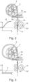
- Fig. 2 shows an example of the case of a fault-free OPT head section 3b during pushing. Since the latching in the OPT head part 3b functions reliably here, the OPT band part end 3a moves laterally out of the original position 3a' when the motor 1b' and thus the tensioning gear wheel 1b* rotate in the reverse direction R and thus push the OPT band part end 3a in the push direction S-.
- a force F must be applied to push the end of the OPT band part 3a in the direction of pushing S-.
- This force F is shown in Fig. 2 in an exemplary course for a defect-free OPT head part 3b over the angle of rotation ⁇ of the tensioning gear wheel 1b*.
- the angle of rotation ⁇ thus corresponds to a path length for the OPT band part end 3a pushed in the direction of pushing S.
- the force F to be applied by the motor 1b' for the pushing is greater than a force threshold value F*. In the example shown, it has the non-linear course increasing monotonically with rotation angle ⁇ illustrated by curve nl.
- the force F to be applied is therefore a possible characteristic parameter for the pushing. Since the force F to be applied and the motor current are directly related, the motor current is also a characteristic parameter for the pushing.
- the motor current can in turn be easily determined by the control device 1c and is therefore particularly suitable for checking the quality of the latching in the OPT head part 3b.
- Fig. 3 shows an example of the case of a faulty OPT head part 3b during the pushing. Since the latching in the OPT head part 3b does not function here, the OPT band part end 3a does not deflect sideways, in contrast to the case of reliable latching. Rather, when motor 1b' and thus tensioning gear 1b* rotate in reverse direction R and thus push the OPT band part end 3a in push direction S-, the OPT band part end 3a is pushed back through window 3c. This means that the OPT 3 is no longer tensioned in the original position 3' on the bundle good 2, and the bundle good 3 is not properly bundled.
- the force threshold value F* can thus easily be selected in such a way that during the pushing in pushing direction S- the control device can reliably distinguish between a faulty head part with non-functioning latching and a fault-free head part with functioning latching.
- the motor current determined during the pushing which corresponds to the applied force F, can be compared as a characteristic parameter with a motor current threshold value, which in turn corresponds to the force threshold value F*. If the determined motor current is greater than the motor current threshold value, the latching is fault-free and a positive ("OK") quality check signal can be output. If the determined motor current is less than the motor current threshold value, the latching is faulty and a negative (“not OK", NOK) quality check signal can be output.
Landscapes
- Engineering & Computer Science (AREA)
- Mechanical Engineering (AREA)
- Basic Packing Technique (AREA)
Description
- The disclosure relates to an automatic bundling tool, ABT, for bundling a bundle good with a one-piece-tie or one-piece-fixing-tie, OPT, comprising a guiding device configured to guide an OPT band part end around the bundle good through a window in an OPT head part, and a tensioning device configured to tension the OPT with pulling, in a tensioning direction, the OPT band part end which is guided through the window and to push the OPT band part end against the tensioning direction after the OPT has been tensioned. Here, One-piece-ties, as a generalised concept of cable ties, include ordinary cable ties.
- Typically, in an application cycle of an automatic bundling tool device, a one-piece-tie, also often referred to as a cable tie, is moved in guiding rails of a guiding device, which define a closed path around the bundle good or bundled material. When pushed forward by a pushing device, the one-piece-tie forms a loop around the bundle good to be bundled with the one-piece-tie. In this process, the tip of the band part arranged at one band part end of the OPT is usually guided by narrowing guiding rails towards a head part of the OPT, which is arranged at the other band part end of the OPT, and then pushed through a through-opening of the OPT head part, the through-opening often referred to as a window. A tensioning device then grips the OPT band part end which has been pushed through the window and tensions the OPT around the bundle good by pulling the OPT band part end that has passed through the window in a tensioning direction. Usually, the OPT band part end that protrudes over the head part after tensioning is cut off with a cutting device.
- In the usual one-piece-ties, the head part has a latching claw which latches onto the band part of the OPT with corresponding latching teeth and thus prevents the band part from being pulled out of the window after tensioning (against the tensioning direction) and thus from being pulled back. This ensures that the OPT remains closed and the bundled goods remain tightened as desired.
- With some of the available automatic bundling tools, for example the HellermannTyton Autotool 2000 CPK, it is possible to (indirectly) adjust the force applied for the tensioning, a tensioning force, by influencing a motor current of a tensioning motor associated with the tensioning. For this purpose, during tensioning by the tensioning device, a tensioning gearwheel is brought into engagement with its teeth in the detent teeth of the band part, whereby the tensioning motor assigned to tensioning, for example a step motor or a pulse-controlled DC motor, drives the tensioning gearwheel. The tensioning motor is controlled independently of the other application cycle. This is done by an electronic control unit (ECU) of a control device, which regulates motor speed and/or motor current, i.e. monitors, adjusts and, if necessary, limits or increases it. This can be done, for example, as a function of user input via an input unit of the control device. By controlling the motor speed and/or motor current, the tensioning force can be indirectly checked by using the previously known mathematical relationship between the measured motor current, the resulting torque on the tensioning gear and the force transmitted to the band part.
- Some of the available automatic bundling tool devices, including the HellermannTyton Autotool 2000 CPK, also use the control device with the ECU for other applications: For example, it can be set so that
- the one-piece-tie is not completely closed, i.e. not tensioned with a significantly non-zero tensioning force, in order to create a loose loop of predetermined size, e.g. for sensitive bundles or loose bundles;
- to create a loop with the OPT band part end protruding from the window with a defined length, by the tensioning gear running backwards after tensioning and before cutting off the OPT band part end, thus the tensioning gear ejecting a part of the OPT band part end that was pushed through the window again;
- the protruding OPT band part end is not cut off at all after tensioning by completely ejecting the OPT band part end before cutting in the application cycle; or
- a combination of the above or other possibilities is implemented.
- Exemplary automatic bundling tool devices are described in
EP 3 466 819 B1EP 3 483 075 B1EP 3 068 693 B1WO 2015 067 444 A1 ,US 2017 334 587 A1 orCN 108 791 998 B . - Two problems are of particular relevance here: On the one hand, OPT can tear due to a tension force that is set too high, and on the other hand, the head part of the OPT can be defective. The latter can be caused, for example, by insufficient stability of the latching claw, whether due to production defects or other properties of the OPT such as excessive humidity or temperature.
- In case of tearing, the OPT cannot be tensioned any further and the bundle good is immediately loose, i.e. no longer held together. Such a failure can be easily detected. During tensioning, the motor current increases as the end of the strap is pulled through the window until the set maximum value is reached. If the OPT breaks, on the one hand the set maximum value will not be reached and on the other hand the motor current will suddenly drop, namely at the time of breaking, since no tensioning force and thus no torque has to be applied any more. Accordingly, the control device can output a quality check signal in the form of an error message and stop further processing.
- The situation is more difficult with a defective head part. Since the tensioning force to be applied is practically independent of the condition of the latching or detent claw, the motor current/tensioning distance relation with a defective latching claw, i.e. the relation between the applied motor current and the distance covered by the OPT band part end during tensioning, will essentially be the same as the motor current/tensioning distance relation with a functioning latching claw. Accordingly, monitoring the motor current will not give any indication of a fault even if the OPT cannot maintain the tensioning force permanently.
- In production processes, for example the production of cable harnesses, both errors can cause great difficulties as they directly influence process stability and product quality. This is especially true for automated applications, where the additional process step of a manual inspection becomes necessary as a result.
- The present invention is thus based on the task of improving production processes in which automatic bundling tool devices bundle a good by means of one-piece-ties, and in particular of improving process stability and product quality with the same effort or maintaining them with a decreasing effort.
- This task is solved by the subject-matter of the independent claim. Advantageous embodiments result from the dependent claims, the description and the figures.
- One aspect relates to an automatic bundling tool, or ABT, for bundling a bundle good or bundled material with a one-piece-tie, OPT. In the context of the present disclosure, OPTs are a generalised concept of a standard cable tie. Such a standard cable tie has a cable tie head part with a window, and a cable tie band or strap with an end part that is slid through the window to form a loop that can be used to bundle cables or the like. One-piece-ties or one-piece-fixing-ties (OPTs) further comprise a neck part connecting a foot part to the head part, the foot part comprising an additional fastening means, for example a mushroom-head part, which can be used to fasten the OPT to an object, in the example of the mushroom-head part usually in a hole of the object. The shape or geometry of the OPT can accordingly have a complexity significantly beyond the standard geometry of standard cable ties due to the different possible foot parts.
- The bundling tool device may also be referred to as a bundling tool, and the one-piece-tie may also be referred to as a cable tie. The ABT has a guiding device which is configured to guide an OPT band part end, a cable tie band end, around the bundle good through a through-opening, referred to as a window, in an OPT head part. For this purpose, the guiding device may comprise corresponding guiding rails adapted to the used OPT. The ABT also has a tensioning device which is designed i) to tension the OPT by pulling the end of the OPT band part guided through the window in a tensioning direction and ii) to push the end of the OPT band part against the tensioning direction after the OPT has been tensioned. Here, the tensioning direction can correspond to a forward direction of an associated tensioning motor, and the push direction opposite to the tensioning direction can correspond to a backward direction of the tensioning motor.
- Part of the ABT is a control device which is designed i) to determine or quantify a characteristic parameter for the pushing of the OPT band part end against the tensioning direction and ii) to output a quality check signal as a function of the characteristic parameter for the pushing against the tensioning direction and a reference value predetermined for the characteristic parameter.
- The determining and outputting can be referred to as a quality test cycle or be part of such a quality test cycle. In the quality test cycle, two cases can occur and be identified by the control device on the basis of the determined parameter: case a) of a fault-free head part with a correctly latching claw, and case b) of a faulty head part with a non-latching or unreliable latching claw. #Thus, the quality tested is a product quality, i.e. a quality of the OPTs head part.
- In case a), the latching claw properly engages with the OPT band part and thus prevents the band part from slipping through the head part against the tensioning direction. This causes a force to build up when pushing against the tensioning direction, which must be overcome by the tensioning device to move the band part. If the force is overcome, the OPT band part will break out laterally and thus allow the push against the tensioning direction.
- In case b), the latching claw is not correctly latched with the OPT band part, so that no force or only a greatly reduced force compared to case a) occurs when pushing against the tensioning direction. Case a) and b) can thus be distinguished on the basis of a characteristic parameter of the tensioning mechanism during the pushing. #Consequently, the control device may be configured to determine the characteristic parameter, which is characteristic for the pushing of the OPT band part end, during the pushing, i.e. after the tensioning.
- The parameter can therefore be monitored by the control device, which outputs the quality check signal accordingly - be it an OK signal with a continuation of the application cycle or an NOK or warning signal with a stop of the application cycle. The OK signal and/or the warning signal can be a visual and/or acoustic signal and/or an electronic signal intended for a monitoring device.
- When continuing the application cycle, after the OPT band part end has been pushed against the tensioning direction, the OPT band part end can be pulled back in the tensioning direction to the starting position before pushing, if required. In this way, a cutting of the OPT band part end provided for in the application cycle can be carried out unaffected by the quality test cycle.
- In the approach described here, an already known and available functionality, namely the ejection of the OPT band part end, is used in a new way. By means of the quantified monitored pushing of the OPT band part end back against the tensioning direction, defects that could not be detected automatically so far, namely defective head parts, can be detected. The quality monitoring or inspection takes place "in line" with the tensioning of the OPT, which makes subsequent monitoring steps, such as optical and/or haptic monitoring, superfluous. This results in increased process stability and product quality or eliminates the need for a monitoring step that would otherwise be required after bundling. This can be implemented with a relatively inexpensive firmware update compared to a complete new development of the tools used or additional tools in the application cycle.
- In an advantageous embodiment, it is provided that the control device is configured to determine the characteristic parameter for an OPT band part end that has not, in particular not yet, been completely pushed out of the tensioning device. This has the advantage that the further processing of the OPT band part end is not influenced by the determining, since after the determining the OPT band part end can both be pulled again in the tensioning direction and cut off at a desired point, i.e. it can also be completely ejected in order to remain untrimmed.
- In a further advantageous embodiment, it is provided that the tensioning device comprises a motor, in particular a tension or drive motor. The motor can be a stepper motor. The tensioning motor can drive a tensioning gear wheel which is configured to engage (preferably in a formfit engagement) with the end of the band part pulled/pushed through the window during tensioning. The characteristic parameter here comprises a motor current of the motor of the tensioning device during pushing or is the motor current during pushing, or is or comprises a variable derived from the motor current of the motor during pushing. #This effectively results in an electric power for the pushing is taken into account by the control device. In particular, the characteristic quantity can be or comprise a force derived from the motor current which is required to push the OPT band part end against the tensioning direction after the OPT has been tensioned.
- This has the advantage that the characteristic parameter can be determined particularly precisely and easily, since the motor current is already controlled and thus also monitored for tensioning with a predetermined tensioning force during the pulling of the OPT band part end which is guided through the window. The motor current or variables derived from it are thus easy to measure and particularly suitable for monitoring the pushing.
- It is particularly advantageous here if the motor is a direct current motor, preferably a direct current motor controlled via a pulse-counting encoder and the tensioning device is configured to control the direct current motor with a predetermined number of n control pulses, which can correspond to n motor steps, when pushing against the tensioning direction . Such a DC motor may be referred to as a pulse-controlled DC motor. Alternatively, the motor can also be a stepper motor. Pushing thus corresponds to control pulses (possibly motor steps) corresponding to the reverse direction of the motor, against the tensioning direction, and pulling corresponds to control pulses (possibly motor steps) in the forward direction of the motor, in the tensioning direction. When using a "normal" DC motor, experience has shown that a sufficiently precise control and thus positioning can already be specified, so that the determined parameter is to be determined sufficiently precise and easy and the quality of the latching in the head part can be reliably checked.
- In another advantageous embodiment, it is provided that the control device is configured to determine the characteristic parameter once during the pushing against the tensioning direction. In particular, the characteristic parameter can be determined exactly once or from a single measurement selected from several individual measurements. The determination may refer to a determination for a single point in time as a sufficiently short time interval. Preferably, such a time interval can be predetermined by an (pre-selected) i-th control pulse of the predetermined number of n control pulses , with 0<i<n+1. This has the advantage that the determination can be carried out mathematically in a particularly simple manner and thus quickly and reliably, with low requirements on the control device used.
- In another advantageous embodiment, it is provided that the control device is configured to determine the characteristic parameter for a series of points in time during the pushing against the tensioning direction, and to compare a course of the characteristic parameter with a course of the reference value specified for the characteristic parameter for the output of the quality check signal. This has the advantage that the characteristics of the OPT and the latching of the OPT band part end in the OPT head part can be analysed particularly precisely, and thus a particularly precise statement about the quality of the latching can be made by the control device.
- In another advantageous embodiment, it is provided that the control device is configured to determine the characteristic parameter for a predetermined period of time during the pushing against the tensioning direction, in particular for the period of time of a predetermined number of control pulses or motor steps during the pushing or during the entire pushing, with integrating the characteristic parameter or a measured value on which the characteristic parameter is based over the predetermined period of time. This has the advantage that the determining requires little computational effort, but is implicitly averaged over several measurements and thus the reliability is improved compared to a single measurement.
- In a further advantageous embodiment, it is provided that the reference value specified for the characteristic parameter, in particular the course of the reference value specified for the characteristic parameter, is automatically specified by the control device itself based on a statistical evaluation of the determined characteristic parameter. In particular, this can be done based on an expected value determined for the characteristic parameter, for example as twice or three times the standard deviation for the characteristic parameter. This has the advantage that the reference value does not have to be calculated and specified manually, but the reference value suitable for the desired confidence value is used automatically, without an operator having to deal more closely with the magnitude of forces occurring in the respective application cycle. The operator then only has to check at the start of production for a statistically significant number of passes through the application cycle, for example 10 or 100 passes, that the desired tensioning force is actually achieved with the loadable latching.
- The reference value can also be determined and stored individually for different application cycles. For example, it can be automatically determined for the different positions on a product at which a respective OPT is used which reference value applies there. In conjunction with the described automatic specification of the reference value, a robust and decentralised monitoring of the tensioning force actually achieved via the loadable latching in the different positions in the work process is thus achieved.
- In a further advantageous embodiment, it is provided that the predetermined reference value is a threshold value and the control device is configured to compare the characteristic parameter with the predetermined threshold value and, in particular, to output a positive quality check signal if the characteristic parameter is greater than the threshold value and/or to output a negative quality check signal if the characteristic parameter is less than the threshold value. Especially when the characteristic parameter is the motor current, it is thus possible to check whether the motor current required for pushing is greater than the threshold value, which is associated with the reliable latching in the head part. This has the advantage that the quality of the latching can be monitored particularly easily and reliably.
- In an advantageous embodiment, it is provided that the guiding device has a holding or fixing element which is configured to hold or fix the OPT head part in a predetermined position when the OPT band part end is pushed and thus, when the OPT is fault-free, also fix the OPT head part against the tensioning direction, in particular in the same position as when the OPT is tensioned. The fixing element fixes the head part during pulling and pushing in at least one direction of space, in the tensioning direction and against the tensioning direction. For example, the fixing element can be in the form of a corresponding projection or a fixing claw, which prevents movement of the head part against the tensioning direction, at least for the duration of the push. This has the advantage that a deflection of the head part during the pushing is prevented by design, independent of a contact pressure of the ABT against the bundle good and a stability of the bundle good. This ensures a constant determination of the characteristic parameter and increases the reliability of the quality monitoring.
- Another aspect relates to operating the ABT of any one of the described embodiments.
- Yet another aspect relates to a method of bundling a bundle good with an OPT or cable tie by an ABT, comprising the steps of:
- a) guiding an OPT/cable tie band end around the bundle good and through a window in a head of the OPT/cable tie, by a guiding device of the ABT;
- b) tensioning the OPT/cable tie with pulling the OPT/cable tie band end in a tensioning direction, by a tensioning device of the ABT;
- c) pushing the OPT/cable tie band end against the tensioning direction after the OPT/cable tie has been tensioned, by the tensioning device of the ABT;
- d) determining a force or other characteristic parameter required for pushing the end of the OPT/cable tie against the tensioning direction, by a control device of the ABT;
- e) outputting, by the control means, a quality check signal in dependence on the force #or the other characteristic parameter# required to push against the tensioning direction and a predetermined reference force #or reference value#.
- As further optional process steps, the following can be carried out:
- f1) (Complete) ejection of the OPT/cable tie end without cutting off the OPT/cable tie end, by the tensioning device; or
- f2) Cutting off the OPT/cable tie band end, preferably after the OPT/cable tie band end has been pulled back to the starting position before being pushed, by a cutting device.
- Advantages and advantageous embodiments of the methods correspond to advantages and advantageous embodiments of the automatic bundling tool device.
- The features and combinations of features described above, including the general part of the description, as well as the features and combinations or features disclosed in the figure description or the figures alone, may be used not only alone or in the combination described, but also with other features or without some of the disclosed features, without departing from the scope of the present disclosure. Consequently, embodiments that are not explicitly illustrated and described by the figures, but can be produced by separately combining the individual features disclosed in the figures, are also part of the present disclosure. Therefore, embodiments and combinations of features that do not comprise all features of an originally formulated independent claim are to be considered as disclosed. Furthermore, embodiments and combinations of features that deviate from or go beyond the combinations of features described by the dependencies of the claims are considered disclosed.
- Exemplary embodiments are described in more detail below with reference to schematic drawings. Showing:
- Fig. 1
- a view of an exemplary embodiment of an automatic bundling tool device;
- Fig. 2
- the tensioning device of the automatic bundle tooling of
Fig. 1 when pushing an OPT band part end with defect-free OPT head part; and - Fig. 3
- the tensioning device of the automatic bundling tool device from
Fig. 1 when pushing an OPT band part end with defective OPT head part. - In the figures, the same or functionally identical features are provided with the same reference signs.
-
Fig. 1 schematically shows an exemplary embodiment of an automatic bundling tool 1, automatic bundling tool, ABT, for bundling a bundle good 2 with a one-piece-tie 3, OPT. In this example, the OPT is a classic standard cable tie. - The ABT 1 has a
guiding device 1a which is configured to guide an OPTband part end 3a around the bundle good 2 through awindow 3c in anOPT head part 3b. The ABT 1 also has atensioning device 1b which is designed both for tensioning theOPT 3 by pulling the OPTband part end 3b guided through thewindow 3c in a tensioning direction S+ and for pushing the OPTband part end 3a against the tensioning direction, i.e. in a pushing direction S- (Figs. 2 and 3 ) after theOPT 3 has been tensioned. Furthermore, the ABT 1 also has acontrol device 1c which, on the one hand, is configured to determine a characteristic parameter for the pushing of the OPTband part end 3a against the tensioning direction S+ and, on the other hand, to output a quality check signal as a function of the characteristic parameter for the pushing against the tensioning direction S+ and a reference value predetermined for the characteristic parameter. - In the example shown, the
tensioning device 1b comprises amotor 1b', here a stepper or pulse motor, which drives atensioning gear wheel 1b*. Thetensioning gear wheel 1b* engages with itsteeth 1b# indetent teeth 3a# of the OPTband part end 3a and thus enables tensioning of theOPT 3 in the tensioning direction S+ when themotor 1b' rotates in the forward direction F and pushing of theOPT 3 in the pushing direction S- against the tensioning direction S+ when themotor 1b' rotates in the reverse direction R (Figs. 2 and 3 ). - The characteristic parameter for the pushing is accordingly a motor current of the
motor 1b' here, which is regulated by thecontrol device 1c and determined during the pushing. As explained inFigs. 2 and 3 , the motor current is equivalent to the force required for the pushing. - In order to determine the force required for the pushing particularly reliably on the basis of the motor current, the guiding
device 1a in this example also has a holdingelement 1a', which is designed as an push-counter-hold in order to prevent movement of theOPT head part 3b during the pushing in the pushing direction S-. For this purpose, the holdingelement 1a' holds theOPT head part 3b in a (unchangeably) predetermined position. -
Fig. 2 shows an example of the case of a fault-freeOPT head section 3b during pushing. Since the latching in theOPT head part 3b functions reliably here, the OPTband part end 3a moves laterally out of theoriginal position 3a' when themotor 1b' and thus thetensioning gear wheel 1b* rotate in the reverse direction R and thus push the OPTband part end 3a in the push direction S-. - Since the lateral deflection is accompanied by a considerable deformation of the
OPT 3, a force F must be applied to push the end of theOPT band part 3a in the direction of pushing S-. This force F is shown inFig. 2 in an exemplary course for a defect-freeOPT head part 3b over the angle of rotation ϕ of thetensioning gear wheel 1b*. The angle of rotationϕ thus corresponds to a path length for the OPTband part end 3a pushed in the direction of pushing S. The force F to be applied by themotor 1b' for the pushing is greater than a force threshold value F*. In the example shown, it has the non-linear course increasing monotonically with rotation angle ϕ illustrated by curve nl. - The force F to be applied is therefore a possible characteristic parameter for the pushing. Since the force F to be applied and the motor current are directly related, the motor current is also a characteristic parameter for the pushing. The motor current can in turn be easily determined by the
control device 1c and is therefore particularly suitable for checking the quality of the latching in theOPT head part 3b. -
Fig. 3 shows an example of the case of a faultyOPT head part 3b during the pushing. Since the latching in theOPT head part 3b does not function here, the OPTband part end 3a does not deflect sideways, in contrast to the case of reliable latching. Rather, whenmotor 1b' and thus tensioninggear 1b* rotate in reverse direction R and thus push the OPTband part end 3a in push direction S-, the OPTband part end 3a is pushed back throughwindow 3c. This means that theOPT 3 is no longer tensioned in the original position 3' on the bundle good 2, and the bundle good 3 is not properly bundled. - The pushing of the OPT
band part end 3a in pushing direction S- back through thewindow 3c is not connected with any considerable deformation of theOPT 3, so that only a very small constant force F has to be applied for the pushing of the OPTband part end 3a in pushing direction S-. In the example shown, it has the constant course shown by curve k. - The force threshold value F* can thus easily be selected in such a way that during the pushing in pushing direction S- the control device can reliably distinguish between a faulty head part with non-functioning latching and a fault-free head part with functioning latching. Thus, the motor current determined during the pushing, which corresponds to the applied force F, can be compared as a characteristic parameter with a motor current threshold value, which in turn corresponds to the force threshold value F*. If the determined motor current is greater than the motor current threshold value, the latching is fault-free and a positive ("OK") quality check signal can be output. If the determined motor current is less than the motor current threshold value, the latching is faulty and a negative ("not OK", NOK) quality check signal can be output.
Claims (12)
- An automatic bundling tool device (1), ABT, for bundling a bundle good (2) with a one-piece-tie (3), OPT, comprising- a guiding device (1a) configured to guide an OPT band part end (3a) around the bundle good (2) through a window (3c) in an OPT head part (3b);- a tensioning device (1b) which is configured i) to tension the OPT (3), with a pulling of the OPT band part end (3a) which is guided through the window (3c) in a tensioning direction (S+) and ii) to push the OPT band part end (3a) against the tensioning direction (S+) in a pushing direction (S-) after the OPT (3) has been tensioned;
characterised by- a control device (1c) which is configured i) to determine a characteristic parameter for the pushing of the OPT band part end (3a) against the tensioning direction (S+) and ii) to output a quality check signal as a function of the characteristic parameter for the pushing against the tensioning direction (S+) and a reference value predetermined for the characteristic parameter. - An automatic bundling tool device, ABT (1) according to claim 1, characterised in that
the control device (1c) is configured to determine the characteristic parameter for an OPT band part end (3a) which is not completely pushed out of the tensioning device (1b). - An automatic bundling tool device, ABT (1) according to claim 1 or 2, characterised in that- the tensioning device (1b) comprises a motor, in particular a stepping motor, and-thecharacteristic parameter comprises a motor current of the motor of the tensioning device (1b) or is the motor current, or is or comprises a variable derived from the motor current of the motor, in particular a force (F) which is required to push the OPT band part end (3a) against the tensioning direction (S+) after tensioning of the OPT (3) has taken place.
- An automatic bundling tool device, ABT (1) according to claim 3, characterised in that
the motor is a pulse-controlled direct current motor and the tensioning device (1b) is configured to control the direct current motor with a predetermined number of control pulses while pushing against the tensioning direction (S+) . - An automatic bundling tool device, ABT (1) according to any one of the preceding claims,
characterised in that
the control device (1c) is configured to determine the characteristic parameter once, preferably only once, during the pushing against the tensioning direction (S+), in particular for an i-th control pulse of the predetermined number of n control pulses , with 0<i<n+1. - An automatic bundling tool device, ABT (1) according to any one of claims 1 to 4,
characterised in that
the control device (1c) is configured to determine the characteristic parameter for a series of times during the pushing against the tensioning direction (S+), and to compare a course of the characteristic parameter with a course of the reference value predetermined for the characteristic parameter for the outputting of the quality check signal. - An automatic bundling tool device, ABT (1) according to any one of claims 1 to 4,
characterised in that
the control device (1c) is configured to determine the characteristic parameter for a predetermined period of time during the pushing against the tensioning direction (S+), in particular for the period of time of a predetermined number of motor steps during the pushing or during the entire pushing, with integrating of the characteristic parameter, or a measured value on which the characteristic parameter is based on, over the predetermined period of time. - An automatic bundling tool device, ABT (1) according to any one of the preceding claims,
characterised in that
the reference value predetermined for the characteristic parameter, in particular the course of the reference value predetermined for the characteristic parameter, is predetermined by the control device (1c) itself based on a statistical evaluation of the characteristic parameter determined, in particular based on a expected value for the characteristic parameter, for example as twice or three times the standard deviation for the characteristic parameter. - An automatic bundling tool device, ABT (1) according to any one of the preceding claims,
characterised in that
the predetermined reference value is a threshold value, and the control device (1c) is configured to compare the characteristic parameter with the predetermined threshold value, and in particular to output a positive quality check signal if the characteristic parameter is greater than the threshold value and/or to output a negative quality check signal if the characteristic parameter is less than the threshold value. - An automatic bundling tool device, ABT (1) according to any one of the preceding claims,
characterized in that
the guiding device (1a) comprises a holding element (1a') which is configured to hold the OPT head part (3b) in a predetermined position when the OPT band part end (3a) is pushed against the tensioning direction (S+), in particular in the same position as when the OPT (3) is tensioned. - Method of bundling a bundle good with a one-piece-tie (3), OPT, by an automatic bundling tool device (1), ABT, comprising the steps of:a) guiding an OPT band end around the bundle good and through a window in a head of the OPT, by a guiding device of the ABT;b) tensioning the OPT with pulling the OPT band end in a tensioning direction, by a tensioning device of the ABT; characterized further by the steps of:c) pushing the OPT band end against the tensioning direction after the OPT has been tensioned, by the tensioning device of the ABT;d) determining a force or other characteristic parameter required for pushing the end of the OPT against the tensioning direction, by a control device of the ABT;e) outputting, by the control means, a quality check signal in dependence on the force or the other characteristic parameter required to push against the tensioning direction and a predetermined reference force.
- Method according to claim 11, characterized by the method step of:
ejection of the OPT end without cutting off the OPT end, by the tensioning device; or cutting off the OPT band end, preferably after the OPT band end has been pulled back to the starting position before being pushed, by a cutting device
Applications Claiming Priority (1)
| Application Number | Priority Date | Filing Date | Title |
|---|---|---|---|
| DE202022102045.0U DE202022102045U1 (en) | 2022-04-14 | 2022-04-14 | Automatic bundling tool device, ABT, for bundling a bundle with a one-piece binder with quality monitoring |
Publications (2)
| Publication Number | Publication Date |
|---|---|
| EP4276024A1 EP4276024A1 (en) | 2023-11-15 |
| EP4276024B1 true EP4276024B1 (en) | 2024-08-21 |
Family
ID=87518345
Family Applications (1)
| Application Number | Title | Priority Date | Filing Date |
|---|---|---|---|
| EP23167841.8A Active EP4276024B1 (en) | 2022-04-14 | 2023-04-13 | Automatic bundling tool device, abt, for bundling a bundle good with a one-piece-tie with quality monitoring |
Country Status (6)
| Country | Link |
|---|---|
| US (1) | US20230331412A1 (en) |
| EP (1) | EP4276024B1 (en) |
| JP (1) | JP2023157898A (en) |
| KR (1) | KR20230147546A (en) |
| CN (1) | CN116902278B (en) |
| DE (1) | DE202022102045U1 (en) |
Families Citing this family (7)
| Publication number | Priority date | Publication date | Assignee | Title |
|---|---|---|---|---|
| EP4163215A1 (en) | 2021-10-01 | 2023-04-12 | HellermannTyton GmbH | Automatic bundling tool device optimized for a range of one-piece-tie strap thicknesses |
| USD1012641S1 (en) | 2021-10-25 | 2024-01-30 | Aptiv Technologies Limited | Tool nosepiece |
| US12157240B2 (en) | 2021-10-26 | 2024-12-03 | Hellermanntyton Corporation | Severing a cable tie with a rounded cut |
| DE202022002179U1 (en) | 2022-10-06 | 2024-01-11 | Hellermanntyton Gmbh | Automatic bundling tool device with guide unit for deformed and/or loose one-piece straps |
| US20250083846A1 (en) * | 2023-09-08 | 2025-03-13 | Abb Schweiz Ag | Drive assembly and motor assembly for strap tensioning |
| JP7735040B2 (en) * | 2024-02-07 | 2025-09-08 | 矢崎総業株式会社 | Cable tie attachment device |
| CN118992196B (en) * | 2024-10-10 | 2025-11-25 | 邦固捆扎技术(深圳)有限公司 | An electric belt tightening machine and its usage method |
Family Cites Families (13)
| Publication number | Priority date | Publication date | Assignee | Title |
|---|---|---|---|---|
| DE29617650U1 (en) * | 1996-10-10 | 1998-02-05 | Paul Hellermann GmbH, 25421 Pinneberg | Cable tie tool |
| DE19859672C2 (en) | 1998-12-23 | 2001-04-12 | Raymond A & Cie | Process for the automated bundling of cable harnesses and automatic device for carrying out the process |
| DE102011075629B4 (en) * | 2011-05-11 | 2016-09-15 | Smb Schwede Maschinenbau Gmbh | Method for controlling the tape drive device of a strapping machine and corresponding strapping machine |
| CN102275649B (en) * | 2011-05-26 | 2013-05-01 | 东莞市胜蓝电子有限公司 | Automatic binding tape bunching machine |
| DE102013222924A1 (en) * | 2013-11-11 | 2015-05-28 | Hellermann Tyton Gmbh | Portable cable tie tool |
| DE102014225880A1 (en) * | 2014-12-15 | 2016-06-16 | Krones Aktiengesellschaft | Strapping head and method of handling a strapping band |
| JP6640996B2 (en) * | 2016-04-18 | 2020-02-05 | ヘラマンタイトン株式会社 | Manual binding tool |
| US20170334587A1 (en) | 2016-05-19 | 2017-11-23 | Delphi Technologies, Inc. | Cable Tie Tensioning And Cut Off Tool |
| CN107380564A (en) * | 2017-09-03 | 2017-11-24 | 许修义 | A kind of automatic testing method and structure for tie tool |
| FR3072080B1 (en) | 2017-10-09 | 2019-11-01 | Hellermanntyton Gmbh | MANUAL AUTOMATIC APPARATUS FOR INSTALLING CLAMPS |
| FR3073503B1 (en) | 2017-11-14 | 2019-11-22 | Hellermanntyton Gmbh | MANUAL AUTOMATIC APPARATUS FOR INSTALLING CLAMPS |
| CN108791998B (en) | 2018-06-27 | 2020-01-21 | 芜湖博康机电有限公司 | Strapping gun |
| CN113942703B (en) * | 2021-09-18 | 2023-03-21 | 台州市新大陆电子科技有限公司 | Information processing method of binding machine |
-
2022
- 2022-04-14 DE DE202022102045.0U patent/DE202022102045U1/en active Active
-
2023
- 2023-04-12 US US18/299,477 patent/US20230331412A1/en active Pending
- 2023-04-13 EP EP23167841.8A patent/EP4276024B1/en active Active
- 2023-04-13 KR KR1020230048892A patent/KR20230147546A/en active Pending
- 2023-04-14 JP JP2023066591A patent/JP2023157898A/en active Pending
- 2023-04-14 CN CN202310403137.0A patent/CN116902278B/en active Active
Also Published As
| Publication number | Publication date |
|---|---|
| DE202022102045U1 (en) | 2023-07-19 |
| EP4276024A1 (en) | 2023-11-15 |
| US20230331412A1 (en) | 2023-10-19 |
| CN116902278A (en) | 2023-10-20 |
| CN116902278B (en) | 2026-01-30 |
| KR20230147546A (en) | 2023-10-23 |
| JP2023157898A (en) | 2023-10-26 |
Similar Documents
| Publication | Publication Date | Title |
|---|---|---|
| EP4276024A1 (en) | Automatic bundling tool device, abt, for bundling a bundle good with a one-piece-tie with quality monitoring | |
| US11130217B2 (en) | Automatic screw tightening control method and device | |
| CN109625385B (en) | Manual self-acting device for assembling tightening strap | |
| JP6698525B2 (en) | Portable cable fastener | |
| KR102576948B1 (en) | Manual automatic device for fitting cable ties | |
| CN108115911B (en) | The control device and management system of injection machine | |
| US7012397B2 (en) | Encoder and control apparatus for motor | |
| EP1344003A2 (en) | Method for conducting a cooking process with a cooking process probe | |
| US5515294A (en) | Method and apparatus for testing coiled materials | |
| EP2311773A1 (en) | Method and device for applying screw caps to containers, in particular bottles | |
| EP3064302B1 (en) | Wire electric discharge machine having function to correct detected value of tensile force | |
| DE19806996A1 (en) | Electronic throttle control system for combustion engine | |
| CN114850853B (en) | Method and apparatus for monitoring and/or adjusting a hot melt tapping process | |
| US7871257B2 (en) | Injection molding machine | |
| KR101666143B1 (en) | Control method of electrically-drive tool | |
| JP4016799B2 (en) | Rebar binding machine | |
| JP3562582B2 (en) | Control method and control device for injection molding machine | |
| US20240286781A1 (en) | Bundling Tool for Waste-Free Bundling of Binding Material | |
| US20130255052A1 (en) | Brake cable tensioning and calibration system and method | |
| JP2013166212A (en) | Tightening error detecting method and device | |
| US20050061090A1 (en) | System and method for the detection of a defect in a drive belt | |
| JP7569032B1 (en) | Electric driver system and driver control device | |
| JP2024165365A (en) | INKJET DEVICE AND METHOD FOR DETECTING PRINTING ERRORS IN INKJET DEVICE - Patent application | |
| CN117412828A (en) | Control method of welding device | |
| EP1447157A1 (en) | Method for controlling the forming operation of blind fasteners |
Legal Events
| Date | Code | Title | Description |
|---|---|---|---|
| PUAI | Public reference made under article 153(3) epc to a published international application that has entered the european phase |
Free format text: ORIGINAL CODE: 0009012 |
|
| STAA | Information on the status of an ep patent application or granted ep patent |
Free format text: STATUS: THE APPLICATION HAS BEEN PUBLISHED |
|
| AK | Designated contracting states |
Kind code of ref document: A1 Designated state(s): AL AT BE BG CH CY CZ DE DK EE ES FI FR GB GR HR HU IE IS IT LI LT LU LV MC ME MK MT NL NO PL PT RO RS SE SI SK SM TR |
|
| STAA | Information on the status of an ep patent application or granted ep patent |
Free format text: STATUS: REQUEST FOR EXAMINATION WAS MADE |
|
| 17P | Request for examination filed |
Effective date: 20240306 |
|
| RBV | Designated contracting states (corrected) |
Designated state(s): AL AT BE BG CH CY CZ DE DK EE ES FI FR GB GR HR HU IE IS IT LI LT LU LV MC ME MK MT NL NO PL PT RO RS SE SI SK SM TR |
|
| GRAP | Despatch of communication of intention to grant a patent |
Free format text: ORIGINAL CODE: EPIDOSNIGR1 |
|
| STAA | Information on the status of an ep patent application or granted ep patent |
Free format text: STATUS: GRANT OF PATENT IS INTENDED |
|
| RIC1 | Information provided on ipc code assigned before grant |
Ipc: B65B 27/10 20060101ALI20240405BHEP Ipc: B65B 13/22 20060101ALI20240405BHEP Ipc: B65B 13/02 20060101AFI20240405BHEP |
|
| INTG | Intention to grant announced |
Effective date: 20240425 |
|
| GRAS | Grant fee paid |
Free format text: ORIGINAL CODE: EPIDOSNIGR3 |
|
| P01 | Opt-out of the competence of the unified patent court (upc) registered |
Free format text: CASE NUMBER: APP_34005/2024 Effective date: 20240606 |
|
| GRAA | (expected) grant |
Free format text: ORIGINAL CODE: 0009210 |
|
| STAA | Information on the status of an ep patent application or granted ep patent |
Free format text: STATUS: THE PATENT HAS BEEN GRANTED |
|
| AK | Designated contracting states |
Kind code of ref document: B1 Designated state(s): AL AT BE BG CH CY CZ DE DK EE ES FI FR GB GR HR HU IE IS IT LI LT LU LV MC ME MK MT NL NO PL PT RO RS SE SI SK SM TR |
|
| REG | Reference to a national code |
Ref country code: GB Ref legal event code: FG4D |
|
| REG | Reference to a national code |
Ref country code: CH Ref legal event code: EP |
|
| REG | Reference to a national code |
Ref country code: IE Ref legal event code: FG4D |
|
| REG | Reference to a national code |
Ref country code: DE Ref legal event code: R096 Ref document number: 602023000422 Country of ref document: DE |
|
| REG | Reference to a national code |
Ref country code: LT Ref legal event code: MG9D |
|
| REG | Reference to a national code |
Ref country code: NL Ref legal event code: MP Effective date: 20240821 |
|
| PG25 | Lapsed in a contracting state [announced via postgrant information from national office to epo] |
Ref country code: NO Free format text: LAPSE BECAUSE OF FAILURE TO SUBMIT A TRANSLATION OF THE DESCRIPTION OR TO PAY THE FEE WITHIN THE PRESCRIBED TIME-LIMIT Effective date: 20241121 |
|
| REG | Reference to a national code |
Ref country code: AT Ref legal event code: MK05 Ref document number: 1715295 Country of ref document: AT Kind code of ref document: T Effective date: 20240821 |
|
| PG25 | Lapsed in a contracting state [announced via postgrant information from national office to epo] |
Ref country code: NL Free format text: LAPSE BECAUSE OF FAILURE TO SUBMIT A TRANSLATION OF THE DESCRIPTION OR TO PAY THE FEE WITHIN THE PRESCRIBED TIME-LIMIT Effective date: 20240821 Ref country code: PL Free format text: LAPSE BECAUSE OF FAILURE TO SUBMIT A TRANSLATION OF THE DESCRIPTION OR TO PAY THE FEE WITHIN THE PRESCRIBED TIME-LIMIT Effective date: 20240821 Ref country code: FI Free format text: LAPSE BECAUSE OF FAILURE TO SUBMIT A TRANSLATION OF THE DESCRIPTION OR TO PAY THE FEE WITHIN THE PRESCRIBED TIME-LIMIT Effective date: 20240821 Ref country code: GR Free format text: LAPSE BECAUSE OF FAILURE TO SUBMIT A TRANSLATION OF THE DESCRIPTION OR TO PAY THE FEE WITHIN THE PRESCRIBED TIME-LIMIT Effective date: 20241122 Ref country code: PT Free format text: LAPSE BECAUSE OF FAILURE TO SUBMIT A TRANSLATION OF THE DESCRIPTION OR TO PAY THE FEE WITHIN THE PRESCRIBED TIME-LIMIT Effective date: 20241223 |
|
| PG25 | Lapsed in a contracting state [announced via postgrant information from national office to epo] |
Ref country code: BG Free format text: LAPSE BECAUSE OF FAILURE TO SUBMIT A TRANSLATION OF THE DESCRIPTION OR TO PAY THE FEE WITHIN THE PRESCRIBED TIME-LIMIT Effective date: 20240821 |
|
| PG25 | Lapsed in a contracting state [announced via postgrant information from national office to epo] |
Ref country code: LV Free format text: LAPSE BECAUSE OF FAILURE TO SUBMIT A TRANSLATION OF THE DESCRIPTION OR TO PAY THE FEE WITHIN THE PRESCRIBED TIME-LIMIT Effective date: 20240821 |
|
| PG25 | Lapsed in a contracting state [announced via postgrant information from national office to epo] |
Ref country code: AT Free format text: LAPSE BECAUSE OF FAILURE TO SUBMIT A TRANSLATION OF THE DESCRIPTION OR TO PAY THE FEE WITHIN THE PRESCRIBED TIME-LIMIT Effective date: 20240821 Ref country code: IS Free format text: LAPSE BECAUSE OF FAILURE TO SUBMIT A TRANSLATION OF THE DESCRIPTION OR TO PAY THE FEE WITHIN THE PRESCRIBED TIME-LIMIT Effective date: 20241221 |
|
| PG25 | Lapsed in a contracting state [announced via postgrant information from national office to epo] |
Ref country code: HR Free format text: LAPSE BECAUSE OF FAILURE TO SUBMIT A TRANSLATION OF THE DESCRIPTION OR TO PAY THE FEE WITHIN THE PRESCRIBED TIME-LIMIT Effective date: 20240821 |
|
| PG25 | Lapsed in a contracting state [announced via postgrant information from national office to epo] |
Ref country code: ES Free format text: LAPSE BECAUSE OF FAILURE TO SUBMIT A TRANSLATION OF THE DESCRIPTION OR TO PAY THE FEE WITHIN THE PRESCRIBED TIME-LIMIT Effective date: 20240821 Ref country code: RS Free format text: LAPSE BECAUSE OF FAILURE TO SUBMIT A TRANSLATION OF THE DESCRIPTION OR TO PAY THE FEE WITHIN THE PRESCRIBED TIME-LIMIT Effective date: 20241121 |
|
| PG25 | Lapsed in a contracting state [announced via postgrant information from national office to epo] |
Ref country code: RS Free format text: LAPSE BECAUSE OF FAILURE TO SUBMIT A TRANSLATION OF THE DESCRIPTION OR TO PAY THE FEE WITHIN THE PRESCRIBED TIME-LIMIT Effective date: 20241121 Ref country code: PT Free format text: LAPSE BECAUSE OF FAILURE TO SUBMIT A TRANSLATION OF THE DESCRIPTION OR TO PAY THE FEE WITHIN THE PRESCRIBED TIME-LIMIT Effective date: 20241223 Ref country code: PL Free format text: LAPSE BECAUSE OF FAILURE TO SUBMIT A TRANSLATION OF THE DESCRIPTION OR TO PAY THE FEE WITHIN THE PRESCRIBED TIME-LIMIT Effective date: 20240821 Ref country code: NO Free format text: LAPSE BECAUSE OF FAILURE TO SUBMIT A TRANSLATION OF THE DESCRIPTION OR TO PAY THE FEE WITHIN THE PRESCRIBED TIME-LIMIT Effective date: 20241121 Ref country code: NL Free format text: LAPSE BECAUSE OF FAILURE TO SUBMIT A TRANSLATION OF THE DESCRIPTION OR TO PAY THE FEE WITHIN THE PRESCRIBED TIME-LIMIT Effective date: 20240821 Ref country code: LV Free format text: LAPSE BECAUSE OF FAILURE TO SUBMIT A TRANSLATION OF THE DESCRIPTION OR TO PAY THE FEE WITHIN THE PRESCRIBED TIME-LIMIT Effective date: 20240821 Ref country code: IS Free format text: LAPSE BECAUSE OF FAILURE TO SUBMIT A TRANSLATION OF THE DESCRIPTION OR TO PAY THE FEE WITHIN THE PRESCRIBED TIME-LIMIT Effective date: 20241221 Ref country code: HR Free format text: LAPSE BECAUSE OF FAILURE TO SUBMIT A TRANSLATION OF THE DESCRIPTION OR TO PAY THE FEE WITHIN THE PRESCRIBED TIME-LIMIT Effective date: 20240821 Ref country code: GR Free format text: LAPSE BECAUSE OF FAILURE TO SUBMIT A TRANSLATION OF THE DESCRIPTION OR TO PAY THE FEE WITHIN THE PRESCRIBED TIME-LIMIT Effective date: 20241122 Ref country code: FI Free format text: LAPSE BECAUSE OF FAILURE TO SUBMIT A TRANSLATION OF THE DESCRIPTION OR TO PAY THE FEE WITHIN THE PRESCRIBED TIME-LIMIT Effective date: 20240821 Ref country code: ES Free format text: LAPSE BECAUSE OF FAILURE TO SUBMIT A TRANSLATION OF THE DESCRIPTION OR TO PAY THE FEE WITHIN THE PRESCRIBED TIME-LIMIT Effective date: 20240821 Ref country code: BG Free format text: LAPSE BECAUSE OF FAILURE TO SUBMIT A TRANSLATION OF THE DESCRIPTION OR TO PAY THE FEE WITHIN THE PRESCRIBED TIME-LIMIT Effective date: 20240821 Ref country code: AT Free format text: LAPSE BECAUSE OF FAILURE TO SUBMIT A TRANSLATION OF THE DESCRIPTION OR TO PAY THE FEE WITHIN THE PRESCRIBED TIME-LIMIT Effective date: 20240821 |
|
| PG25 | Lapsed in a contracting state [announced via postgrant information from national office to epo] |
Ref country code: DK Free format text: LAPSE BECAUSE OF FAILURE TO SUBMIT A TRANSLATION OF THE DESCRIPTION OR TO PAY THE FEE WITHIN THE PRESCRIBED TIME-LIMIT Effective date: 20240821 Ref country code: RO Free format text: LAPSE BECAUSE OF FAILURE TO SUBMIT A TRANSLATION OF THE DESCRIPTION OR TO PAY THE FEE WITHIN THE PRESCRIBED TIME-LIMIT Effective date: 20240821 Ref country code: SM Free format text: LAPSE BECAUSE OF FAILURE TO SUBMIT A TRANSLATION OF THE DESCRIPTION OR TO PAY THE FEE WITHIN THE PRESCRIBED TIME-LIMIT Effective date: 20240821 |
|
| PG25 | Lapsed in a contracting state [announced via postgrant information from national office to epo] |
Ref country code: EE Free format text: LAPSE BECAUSE OF FAILURE TO SUBMIT A TRANSLATION OF THE DESCRIPTION OR TO PAY THE FEE WITHIN THE PRESCRIBED TIME-LIMIT Effective date: 20240821 |
|
| PG25 | Lapsed in a contracting state [announced via postgrant information from national office to epo] |
Ref country code: CZ Free format text: LAPSE BECAUSE OF FAILURE TO SUBMIT A TRANSLATION OF THE DESCRIPTION OR TO PAY THE FEE WITHIN THE PRESCRIBED TIME-LIMIT Effective date: 20240821 |
|
| PG25 | Lapsed in a contracting state [announced via postgrant information from national office to epo] |
Ref country code: IT Free format text: LAPSE BECAUSE OF FAILURE TO SUBMIT A TRANSLATION OF THE DESCRIPTION OR TO PAY THE FEE WITHIN THE PRESCRIBED TIME-LIMIT Effective date: 20240821 Ref country code: SK Free format text: LAPSE BECAUSE OF FAILURE TO SUBMIT A TRANSLATION OF THE DESCRIPTION OR TO PAY THE FEE WITHIN THE PRESCRIBED TIME-LIMIT Effective date: 20240821 |
|
| REG | Reference to a national code |
Ref country code: DE Ref legal event code: R097 Ref document number: 602023000422 Country of ref document: DE |
|
| PLBE | No opposition filed within time limit |
Free format text: ORIGINAL CODE: 0009261 |
|
| STAA | Information on the status of an ep patent application or granted ep patent |
Free format text: STATUS: NO OPPOSITION FILED WITHIN TIME LIMIT |
|
| PGFP | Annual fee paid to national office [announced via postgrant information from national office to epo] |
Ref country code: DE Payment date: 20250313 Year of fee payment: 3 |
|
| 26N | No opposition filed |
Effective date: 20250522 |
|
| PG25 | Lapsed in a contracting state [announced via postgrant information from national office to epo] |
Ref country code: SE Free format text: LAPSE BECAUSE OF FAILURE TO SUBMIT A TRANSLATION OF THE DESCRIPTION OR TO PAY THE FEE WITHIN THE PRESCRIBED TIME-LIMIT Effective date: 20240821 |
|
| REG | Reference to a national code |
Ref country code: DE Ref legal event code: R081 Ref document number: 602023000422 Country of ref document: DE Owner name: HELLERMANNTYTON GMBH & CO. KG, DE Free format text: FORMER OWNER: HELLERMANNTYTON GMBH, 25436 TORNESCH, DE |
|
| PG25 | Lapsed in a contracting state [announced via postgrant information from national office to epo] |
Ref country code: LU Free format text: LAPSE BECAUSE OF NON-PAYMENT OF DUE FEES Effective date: 20250413 |
|
| PG25 | Lapsed in a contracting state [announced via postgrant information from national office to epo] |
Ref country code: MC Free format text: LAPSE BECAUSE OF FAILURE TO SUBMIT A TRANSLATION OF THE DESCRIPTION OR TO PAY THE FEE WITHIN THE PRESCRIBED TIME-LIMIT Effective date: 20240821 |
|
| REG | Reference to a national code |
Ref country code: BE Ref legal event code: MM Effective date: 20250430 |
|
| PG25 | Lapsed in a contracting state [announced via postgrant information from national office to epo] |
Ref country code: BE Free format text: LAPSE BECAUSE OF NON-PAYMENT OF DUE FEES Effective date: 20250430 |
|
| PG25 | Lapsed in a contracting state [announced via postgrant information from national office to epo] |
Ref country code: IE Free format text: LAPSE BECAUSE OF NON-PAYMENT OF DUE FEES Effective date: 20250413 |
|
| PGFP | Annual fee paid to national office [announced via postgrant information from national office to epo] |
Ref country code: FR Payment date: 20260303 Year of fee payment: 4 |