EP4275974A1 - Electro-mechanical brake and control method thereof - Google Patents
Electro-mechanical brake and control method thereof Download PDFInfo
- Publication number
- EP4275974A1 EP4275974A1 EP22192085.3A EP22192085A EP4275974A1 EP 4275974 A1 EP4275974 A1 EP 4275974A1 EP 22192085 A EP22192085 A EP 22192085A EP 4275974 A1 EP4275974 A1 EP 4275974A1
- Authority
- EP
- European Patent Office
- Prior art keywords
- piston
- contact point
- current
- motor
- stiffness
- Prior art date
- Legal status (The legal status is an assumption and is not a legal conclusion. Google has not performed a legal analysis and makes no representation as to the accuracy of the status listed.)
- Granted
Links
Images








Classifications
-
- B—PERFORMING OPERATIONS; TRANSPORTING
- B60—VEHICLES IN GENERAL
- B60T—VEHICLE BRAKE CONTROL SYSTEMS OR PARTS THEREOF; BRAKE CONTROL SYSTEMS OR PARTS THEREOF, IN GENERAL; ARRANGEMENT OF BRAKING ELEMENTS ON VEHICLES IN GENERAL; PORTABLE DEVICES FOR PREVENTING UNWANTED MOVEMENT OF VEHICLES; VEHICLE MODIFICATIONS TO FACILITATE COOLING OF BRAKES
- B60T13/00—Transmitting braking action from initiating means to ultimate brake actuator with power assistance or drive; Brake systems incorporating such transmitting means, e.g. air-pressure brake systems
- B60T13/74—Transmitting braking action from initiating means to ultimate brake actuator with power assistance or drive; Brake systems incorporating such transmitting means, e.g. air-pressure brake systems with electrical assistance or drive
- B60T13/741—Transmitting braking action from initiating means to ultimate brake actuator with power assistance or drive; Brake systems incorporating such transmitting means, e.g. air-pressure brake systems with electrical assistance or drive acting on an ultimate actuator
-
- B—PERFORMING OPERATIONS; TRANSPORTING
- B60—VEHICLES IN GENERAL
- B60T—VEHICLE BRAKE CONTROL SYSTEMS OR PARTS THEREOF; BRAKE CONTROL SYSTEMS OR PARTS THEREOF, IN GENERAL; ARRANGEMENT OF BRAKING ELEMENTS ON VEHICLES IN GENERAL; PORTABLE DEVICES FOR PREVENTING UNWANTED MOVEMENT OF VEHICLES; VEHICLE MODIFICATIONS TO FACILITATE COOLING OF BRAKES
- B60T13/00—Transmitting braking action from initiating means to ultimate brake actuator with power assistance or drive; Brake systems incorporating such transmitting means, e.g. air-pressure brake systems
- B60T13/74—Transmitting braking action from initiating means to ultimate brake actuator with power assistance or drive; Brake systems incorporating such transmitting means, e.g. air-pressure brake systems with electrical assistance or drive
-
- B—PERFORMING OPERATIONS; TRANSPORTING
- B60—VEHICLES IN GENERAL
- B60T—VEHICLE BRAKE CONTROL SYSTEMS OR PARTS THEREOF; BRAKE CONTROL SYSTEMS OR PARTS THEREOF, IN GENERAL; ARRANGEMENT OF BRAKING ELEMENTS ON VEHICLES IN GENERAL; PORTABLE DEVICES FOR PREVENTING UNWANTED MOVEMENT OF VEHICLES; VEHICLE MODIFICATIONS TO FACILITATE COOLING OF BRAKES
- B60T8/00—Arrangements for adjusting wheel-braking force to meet varying vehicular or ground-surface conditions, e.g. limiting or varying distribution of braking force
- B60T8/17—Using electrical or electronic regulation means to control braking
- B60T8/172—Determining control parameters used in the regulation, e.g. by calculations involving measured or detected parameters
-
- B—PERFORMING OPERATIONS; TRANSPORTING
- B60—VEHICLES IN GENERAL
- B60T—VEHICLE BRAKE CONTROL SYSTEMS OR PARTS THEREOF; BRAKE CONTROL SYSTEMS OR PARTS THEREOF, IN GENERAL; ARRANGEMENT OF BRAKING ELEMENTS ON VEHICLES IN GENERAL; PORTABLE DEVICES FOR PREVENTING UNWANTED MOVEMENT OF VEHICLES; VEHICLE MODIFICATIONS TO FACILITATE COOLING OF BRAKES
- B60T17/00—Component parts, details, or accessories of power brake systems not covered by groups B60T8/00, B60T13/00 or B60T15/00, or presenting other characteristic features
- B60T17/18—Safety devices; Monitoring
- B60T17/22—Devices for monitoring or checking brake systems; Signal devices
-
- B—PERFORMING OPERATIONS; TRANSPORTING
- B60—VEHICLES IN GENERAL
- B60T—VEHICLE BRAKE CONTROL SYSTEMS OR PARTS THEREOF; BRAKE CONTROL SYSTEMS OR PARTS THEREOF, IN GENERAL; ARRANGEMENT OF BRAKING ELEMENTS ON VEHICLES IN GENERAL; PORTABLE DEVICES FOR PREVENTING UNWANTED MOVEMENT OF VEHICLES; VEHICLE MODIFICATIONS TO FACILITATE COOLING OF BRAKES
- B60T13/00—Transmitting braking action from initiating means to ultimate brake actuator with power assistance or drive; Brake systems incorporating such transmitting means, e.g. air-pressure brake systems
- B60T13/74—Transmitting braking action from initiating means to ultimate brake actuator with power assistance or drive; Brake systems incorporating such transmitting means, e.g. air-pressure brake systems with electrical assistance or drive
- B60T13/746—Transmitting braking action from initiating means to ultimate brake actuator with power assistance or drive; Brake systems incorporating such transmitting means, e.g. air-pressure brake systems with electrical assistance or drive and mechanical transmission of the braking action
-
- B—PERFORMING OPERATIONS; TRANSPORTING
- B60—VEHICLES IN GENERAL
- B60T—VEHICLE BRAKE CONTROL SYSTEMS OR PARTS THEREOF; BRAKE CONTROL SYSTEMS OR PARTS THEREOF, IN GENERAL; ARRANGEMENT OF BRAKING ELEMENTS ON VEHICLES IN GENERAL; PORTABLE DEVICES FOR PREVENTING UNWANTED MOVEMENT OF VEHICLES; VEHICLE MODIFICATIONS TO FACILITATE COOLING OF BRAKES
- B60T8/00—Arrangements for adjusting wheel-braking force to meet varying vehicular or ground-surface conditions, e.g. limiting or varying distribution of braking force
- B60T8/17—Using electrical or electronic regulation means to control braking
- B60T8/171—Detecting parameters used in the regulation; Measuring values used in the regulation
-
- B—PERFORMING OPERATIONS; TRANSPORTING
- B60—VEHICLES IN GENERAL
- B60T—VEHICLE BRAKE CONTROL SYSTEMS OR PARTS THEREOF; BRAKE CONTROL SYSTEMS OR PARTS THEREOF, IN GENERAL; ARRANGEMENT OF BRAKING ELEMENTS ON VEHICLES IN GENERAL; PORTABLE DEVICES FOR PREVENTING UNWANTED MOVEMENT OF VEHICLES; VEHICLE MODIFICATIONS TO FACILITATE COOLING OF BRAKES
- B60T8/00—Arrangements for adjusting wheel-braking force to meet varying vehicular or ground-surface conditions, e.g. limiting or varying distribution of braking force
- B60T8/17—Using electrical or electronic regulation means to control braking
- B60T8/173—Eliminating or reducing the effect of unwanted signals, e.g. due to vibrations or electrical noise
-
- F—MECHANICAL ENGINEERING; LIGHTING; HEATING; WEAPONS; BLASTING
- F16—ENGINEERING ELEMENTS AND UNITS; GENERAL MEASURES FOR PRODUCING AND MAINTAINING EFFECTIVE FUNCTIONING OF MACHINES OR INSTALLATIONS; THERMAL INSULATION IN GENERAL
- F16D—COUPLINGS FOR TRANSMITTING ROTATION; CLUTCHES; BRAKES
- F16D55/00—Brakes with substantially-radial braking surfaces pressed together in axial direction, e.g. disc brakes
- F16D55/02—Brakes with substantially-radial braking surfaces pressed together in axial direction, e.g. disc brakes with axially-movable discs or pads pressed against axially-located rotating members
- F16D55/22—Brakes with substantially-radial braking surfaces pressed together in axial direction, e.g. disc brakes with axially-movable discs or pads pressed against axially-located rotating members by clamping an axially-located rotating disc between movable braking members, e.g. movable brake discs or brake pads
- F16D55/224—Brakes with substantially-radial braking surfaces pressed together in axial direction, e.g. disc brakes with axially-movable discs or pads pressed against axially-located rotating members by clamping an axially-located rotating disc between movable braking members, e.g. movable brake discs or brake pads with a common actuating member for the braking members
- F16D55/225—Brakes with substantially-radial braking surfaces pressed together in axial direction, e.g. disc brakes with axially-movable discs or pads pressed against axially-located rotating members by clamping an axially-located rotating disc between movable braking members, e.g. movable brake discs or brake pads with a common actuating member for the braking members the braking members being brake pads
- F16D55/226—Brakes with substantially-radial braking surfaces pressed together in axial direction, e.g. disc brakes with axially-movable discs or pads pressed against axially-located rotating members by clamping an axially-located rotating disc between movable braking members, e.g. movable brake discs or brake pads with a common actuating member for the braking members the braking members being brake pads in which the common actuating member is moved axially, e.g. floating caliper disc brakes
-
- F—MECHANICAL ENGINEERING; LIGHTING; HEATING; WEAPONS; BLASTING
- F16—ENGINEERING ELEMENTS AND UNITS; GENERAL MEASURES FOR PRODUCING AND MAINTAINING EFFECTIVE FUNCTIONING OF MACHINES OR INSTALLATIONS; THERMAL INSULATION IN GENERAL
- F16D—COUPLINGS FOR TRANSMITTING ROTATION; CLUTCHES; BRAKES
- F16D65/00—Parts or details
- F16D65/14—Actuating mechanisms for brakes; Means for initiating operation at a predetermined position
- F16D65/16—Actuating mechanisms for brakes; Means for initiating operation at a predetermined position arranged in or on the brake
- F16D65/18—Actuating mechanisms for brakes; Means for initiating operation at a predetermined position arranged in or on the brake adapted for drawing members together, e.g. for disc brakes
-
- B—PERFORMING OPERATIONS; TRANSPORTING
- B60—VEHICLES IN GENERAL
- B60T—VEHICLE BRAKE CONTROL SYSTEMS OR PARTS THEREOF; BRAKE CONTROL SYSTEMS OR PARTS THEREOF, IN GENERAL; ARRANGEMENT OF BRAKING ELEMENTS ON VEHICLES IN GENERAL; PORTABLE DEVICES FOR PREVENTING UNWANTED MOVEMENT OF VEHICLES; VEHICLE MODIFICATIONS TO FACILITATE COOLING OF BRAKES
- B60T2270/00—Further aspects of brake control systems not otherwise provided for
- B60T2270/84—Driver circuits for actuating motor, valve and the like
-
- B—PERFORMING OPERATIONS; TRANSPORTING
- B60—VEHICLES IN GENERAL
- B60T—VEHICLE BRAKE CONTROL SYSTEMS OR PARTS THEREOF; BRAKE CONTROL SYSTEMS OR PARTS THEREOF, IN GENERAL; ARRANGEMENT OF BRAKING ELEMENTS ON VEHICLES IN GENERAL; PORTABLE DEVICES FOR PREVENTING UNWANTED MOVEMENT OF VEHICLES; VEHICLE MODIFICATIONS TO FACILITATE COOLING OF BRAKES
- B60T2270/00—Further aspects of brake control systems not otherwise provided for
- B60T2270/88—Pressure measurement in brake systems
-
- B—PERFORMING OPERATIONS; TRANSPORTING
- B60—VEHICLES IN GENERAL
- B60Y—INDEXING SCHEME RELATING TO ASPECTS CROSS-CUTTING VEHICLE TECHNOLOGY
- B60Y2400/00—Special features of vehicle units
- B60Y2400/30—Sensors
- B60Y2400/301—Sensors for position or displacement
-
- B—PERFORMING OPERATIONS; TRANSPORTING
- B60—VEHICLES IN GENERAL
- B60Y—INDEXING SCHEME RELATING TO ASPECTS CROSS-CUTTING VEHICLE TECHNOLOGY
- B60Y2400/00—Special features of vehicle units
- B60Y2400/30—Sensors
- B60Y2400/308—Electric sensors
- B60Y2400/3084—Electric currents sensors
-
- F—MECHANICAL ENGINEERING; LIGHTING; HEATING; WEAPONS; BLASTING
- F16—ENGINEERING ELEMENTS AND UNITS; GENERAL MEASURES FOR PRODUCING AND MAINTAINING EFFECTIVE FUNCTIONING OF MACHINES OR INSTALLATIONS; THERMAL INSULATION IN GENERAL
- F16D—COUPLINGS FOR TRANSMITTING ROTATION; CLUTCHES; BRAKES
- F16D2121/00—Type of actuator operation force
- F16D2121/18—Electric or magnetic
- F16D2121/24—Electric or magnetic using motors
Definitions
- the present disclosure relates to an electro-mechanical brake and a control method thereof.
- EMB Electro-Mechanical Brake
- the electro-mechanical brake was developed as an Electronic Parking Brake (EPB), but the field of use of the brake is expanding to a main brake which substitutes for a conventional hydraulic brake.
- the EMB is a device in which an actuator driven by a motor is mounted on a brake caliper, so that a vehicle is directly braked by a motor driving force without a medium such as brake fluid. Since the EMB has a mechanism similar to that of the Electronic Parking Brake (EPB) but is mainly used for main braking unlike the EPB, the EMB requires higher braking response and operation durability than those of the EPB. Further, the electro-mechanical brake may be simpler in structure, be higher in braking response speed, and be more precisely controlled compared to the hydraulic brake, thereby improving braking stability.
- An electro-mechanical brake with a force sensor mounted to it is able to accurately measure clamping force.
- mounting a force sensor to an electro-mechanical brake complicates the design and raises the manufacturing cost.
- the mounting of the sensor also increases the size of the electro-mechanical brake.
- a current sensor may be used instead of a force sensor to estimate clamping force.
- the electro-mechanical brake may be designed in such a way that the current sensor measures a current applied to a motor that generates braking force and estimates clamping force based on the measured current.
- a problem with the estimating of clamping force by measuring a current applied to the motor is that this method has lower accuracy compared to using a force sensor, due to a measurement noise from the current sensor.
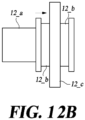
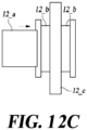
- FIGS. 12A , 12B and 12C are view showing a construction of a conventional electro-mechanical brake.
- the electro-mechanical brake includes a wheel disc 12_c, a pair of brake pads 12_b disposed on both sides of the wheel disc 12_c, and a piston 12a configured to push the brake pads 12_b towards the wheel disc 12_c.
- the braking force varies with the movement path of the piston 12_a. That is, the braking force relative to the position of the piston 12_a has a hysteresis characteristic. Therefore, accurate estimation of braking force requires consideration of the movement path of the piston 12_a.
- the present disclosure provides an electro-mechanical brake comprising a piston to push a brake pad towards a wheel disc by driving a motor in a vehicle; a position detection unit that detects a position of the piston based on a plurality of specified current values; a current detection unit that detects a value of current applied to the motor; and a contact point calculation unit that calculates a contact point, which is where the piston is located when the brake pad starts to come into contact with the wheel disc, based on the position of the piston and the value of the current applied to the motor, or based on a first position of the piston detected by the position detection unit with respect to a plurality of specified current values and a second position of the piston measured with respect to the plurality of specified current values.
- the present disclosure provides a control method of an electro-mechanical brake comprising a piston to push a brake pad towards a wheel disc by driving a motor in a vehicle, the control method comprising: a position detection process including detecting, by a position detection unit, a position of the piston; a current detection process including detecting, by a current detection unit, a value of current applied to the motor; and a contact point calculation process including calculating, by a contact point calculation unit, a contact point, which is where the piston is located when the brake pad starts to come into contact with the wheel disc, is calculated based on the position of the piston and the value of current applied to the motor, or based on a first position of the piston detected by the position detection unit with respect to a plurality of specified current values and a second position of the piston measured with respect to the plurality of specified current values.
- An electro-mechanical brake according to an embodiment of the present disclosure is able to estimate force based on a current applied to a motor and the position of a piston.
- An electro-mechanical brake according to an embodiment of the present disclosure is able to accurately calculate force by calculating and/or calibrating a contact point based on a current applied to a motor and the position of a piston.
- An electro-mechanical brake according to an embodiment of the present disclosure is able to accurately calculate force by calibrating the stiffness of a caliper and an abrasion of pads based on a current applied to a motor and the position of a piston.
- An electro-mechanical brake according to an embodiment of the present disclosure is able to accurately calculate braking force based on a hysteresis characteristic of the braking force relative to the position of a piston.
- various terms such as first, second, A, B, (a), (b), etc. are used solely to differentiate one component from the other but not to imply or suggest the substances, order, or sequence of the components.
- a part 'includes' or 'comprises' a component the part is meant to further include other components, not to exclude thereof unless specifically stated to the contrary.
- the terms such as 'unit', 'module', and the like refer to one or more units for processing at least one function or operation, which may be implemented by hardware, software, or a combination thereof.
- FIG. 1 is a view showing a construction of an electro-mechanical brake according to an embodiment of the present disclosure.
- the electro-mechanical brake includes all or some of a wheel disc 150, a brake pad 140, a piston 131, a motor 120, a current detection unit 180, a position detection unit 170, a hysteresis data storage unit 161, a calculation unit 162, a past state data storage unit 163, a transition section function data generating unit 164, a contact point calculation unit 165, a braking force calculation unit 166, and a motor controller 167.
- the wheel disc 150 is coupled to a wheel of a vehicle.
- the wheel disc 150 is rotated along with the wheel of the vehicle. By restricting the rotation of the wheel disc 150, the vehicle may be braked.
- the brake pad 140 is disposed on a side of the wheel disc 150.
- the piston 131 is configured to push the brake pad 140 toward the wheel disc 150 by driving the motor 120. As the piston 131 presses the brake pad 140 toward the wheel disc 150, a frictional force is generated between the brake pad 140 and the wheel disc 150. Due to the frictional force generated between the brake pad 140 and the wheel disc 150, the rotation of the wheel disc 150 is restricted.
- the motor 120 supplies power to the piston 131.
- a process in which the piston 131 receives power from the motor 120 and then is driven will be described.
- a driving gear 134 is rotated along with a rotating shaft 121 of the motor 120 by driving the motor 120.
- the driving gear 134 engages with a driven gear 133.
- the driven gear 133 is coupled to a screw shaft 132.
- the screw shaft 132 rotates in conjunction with the rotation of the driven gear 133.
- a screw thread is formed on the outer circumference of the screw shaft 132.
- a screw groove having a shape corresponding to that of the screw thread of the screw shaft 132 is formed on the inner circumference of the piston 131.
- the piston 131 moves rectilinearly while being fastened to or unfastened from the screw shaft 132. If the piston 131 moves rectilinearly toward the wheel disc 150, the brake pad 140 is pushed toward the wheel disc 150 by the piston 131.
- the position detection unit 170 detects the position of the piston 131.
- the position of the piston 131 represents a distance from a lowest point of a stroke of the piston 131 to the piston 131.
- the stroke lowest point refers to the position of the brake pad 140 when the brake pad 140 is maximally spaced apart from the wheel disc 150.
- the position detection unit 170 may include an angle sensor.
- the angle sensor measures the angular displacement of the rotating shaft 121 of the motor 120.
- the position detection unit 170 may calculate the rectilinear moving distance of the piston 131 using the angular displacement of the rotating shaft 21 sensed by the angle sensor.
- the rectilinear moving distance of the piston 131 according to the rotating angle of the motor 120 may vary depending on the design of the electro-mechanical brake. For instance, the electro-mechanical brake may be designed such that the rectilinear moving distance of the piston 131 is 1 mm while the rotating shaft 121 of the motor 120 is rotated at 360 degrees.
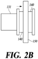
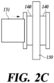
- FIGS. 2A to 2C are view showing an operating state of an electro-mechanical brake according to an embodiment of the present disclosure.
- the braking force is the force for braking the vehicle.
- the piston 131 pushes the brake pad 140 so that the brake pad 140 contacts the wheel disc 150 as shown in FIG. 2B , frictional force is generated between the brake pad 140 and the wheel disc 150.
- the frictional force generated between the brake pad 140 and the wheel disc 150 acts as the braking force.
- the position of the piston 131 where the brake pad 140 starts to contact the wheel disc 150 is referred to as a contact point.
- FIG. 2C when the piston 131 passes through the contact point and moves toward the wheel disc 150, the force of the piston 131 pressing the brake pad 140 is increased.
- the force of the piston 131 pressing the brake pad 140 is referred to as clamping force. If the clamping force increases, the frictional force generated between the brake pad 140 and the wheel disc 150 increases. That is, the braking force increases.
- the electro-mechanical brake according to an embodiment of the present disclosure may estimate the clamping force not by using a load sensor but by using a current sensor and a position sensor.
- the position detection unit 170 may precisely measure the position of the piston 131 using the angle sensor. However, since the contact point varies depending on the wear state of the brake pad 140, the position of the contact point cannot be recognized only by the position of the piston 131. If the contact point is not recognized, it is difficult to precisely estimate the clamping force according to the position of the piston 131.
- the current detection unit 180 detects the value of current flowing through the motor 120.
- the control unit 160 feeds back the current value detected by the current detection unit 180 to control the motor 120.
- the electro-mechanical brake device according to an embodiment of the present disclosure identifies the position of the contact point using current control.
- FIG. 3 is a graph of the current versus moving distance of a braking pad according to an embodiment of the present disclosure.
- the value of current applied to the motor 120 increases in proportion to the position of the piston 131.
- the value of current applied to the motor 120 may increase in proportion to clamping force.
- it is difficult to precisely calculate clamping force because measurements by a current sensor have a large margin of error.
- the current detection unit 180 may include a current sensor that measures a current applied to the motor 120 and a filter (not shown) that removes noise from the measured current.
- the filter may be a low-pass filter.
- the contact point calculation unit 165 may calculate a contact point by using a current from which noise is removed by the filter.
- a time delay may occur. However, this may be solved by moving the piston 131 at a constant speed over time so that the same amount of time delay occurs across the entire range.
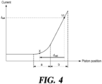
- FIG. 4 is a graph depicting a method of estimating a contact point of an electro-mechanical brake according to an embodiment of the present disclosure.
- the horizontal axis of the graph represents the position of the piston 131, while the vertical axis thereof represents the value of current flowing through the motor 120. As it proceeds to the right on the horizontal axis of the graph, a gap g (see FIG. 1 ) between the brake pad 140 and the wheel disc 150 is reduced.
- the current value of the motor 120 is maintained at a substantially constant value in a section before the contact point X, but the current value is non-linearly increased in a non-linear section a shown in FIG. 4 after the contact point. If the operating distance is further increased past the non-linear section a, the current value is linearly increased in a linear section b shown in FIG. 4 .
- the linear section b refers to a section in which the current value detected using the current detection unit 180 is linearly changed within a predetermined error range for the position of the piston 131.
- the position of the piston 131 when the current detection unit 180 detects the first current value i set is defined as a first position Y1.
- the first current value i set that is a preset value may be a current value on the linear section b.
- the error range occurring in the linear section b is narrower than the error range e occurring in the non-linear section a, so that the contact point can be more accurately calculated.
- the control unit 160 includes all or some of a hysteresis data storage unit 161, a calculation unit 162, a past state data storage unit 163, a transition section function data generating unit 164, a contact point calculation unit 165, a braking force calculation unit 166, and a motor controller 167.
- the contact point calculation unit 165 calculates the contact point X based on the first position Y1 that is the position of the piston 131 when the first current value is detected using the current detection unit 180.
- the contact point calculation unit 165 calculates a second position spaced apart from the first position Y1 by a preset distance d set to an opposite side of the wheel disc 150 as the contact point X.
- the value of the preset distance d set that is an experimentally measured value may vary depending on the specification of the electro-mechanical brake.
- the control unit 160 may determine the relative positions of the brake pad 140 and the wheel disc 150 and the size of an air gap using the position sensor, based on the determined contact point X.
- the motor controller 167 drives the motor 120 for a preset time when the vehicle is stopped, thus moving the piston 131 toward the wheel disc 150.
- the motor controller 167 may drive the motor 120 for a preset time when the vehicle is parked and the door of the vehicle is opened, thus moving the piston 131 toward the wheel disc 150. If the door is opened while the vehicle is parked, the motor controller 167 may drive the motor 120 at a preset angular speed for a preset time.
- the contact point calculation unit 165 may calculate the contact point X.
- the motor controller 167 drives the motor 120 at a preset angular speed for a preset time after the door of the vehicle is opened, thus moving the piston 131 toward the wheel disc 150.
- the motor controller 167 controls the motor 120 to generate a braking force corresponding to a braking signal immediately after a preset time has elapsed.
- FIG. 5 is a graph showing a motor control timing for detecting a contact point of an electro-mechanical brake according to an embodiment of the present disclosure.
- the motor controller 167 drives the motor 120 at a predetermined angular speed for about 2 seconds to move the piston 131 toward the wheel disc 150.
- an operation in which the motor controller 167 drives the motor 120 at a predetermined angular speed for a preset time is referred to as ramp driving.
- the contact point calculation unit 165 identifies the contact point based on the current value data for the position of the piston 131 acquired by the ramp driving.
- the motor controller 167 controls the motor 120 to generate the braking force corresponding to the braking signal that is input using the brake pedal immediately after the ramp driving is finished.
- the ramp driving is performed while the vehicle is parked.
- the motor controller 167 controls the motor 120 so that the electro-mechanical brake generates a demand braking force based on the braking force calculated by the braking force calculation unit 166.
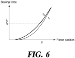
- FIG. 6 is a graph showing the amount of braking force with respect to the position and moving direction of a piston according to an embodiment of the present disclosure.
- the horizontal axis of the graph represents the position of the piston 131.
- the vertical axis of the graph represents the braking force.
- the braking force is not determined only by the position of the piston 131. Even if the piston 131 is at the same position, the braking force when the piston 131 moves toward the wheel disc 150 is different from the braking force when the piston 131 moves to the opposite side of the wheel disc 150. Therefore, in order to accurately estimate the braking force, it is necessary to consider the position of the piston 131 as well as the moving path of the piston 131.
- a function for a rising section in which the braking force is increased as the piston 131 moves toward the wheel disc 150 is referred to as a rising section function f a (see FIG. 6 )
- a function for a falling section in which the braking force is reduced as the piston 131 moves to the opposite side of the wheel disc 150 is referred to as a falling section function f a (see FIG. 6 ).
- FIG. 7 is a graph depicting a process of calculating the braking force of an electro-mechanical brake according to an embodiment of the present disclosure.
- the vertical axis of the graph of FIG. 7 represents the position of the piston 131.
- the position of the piston 131 is set to 0.
- the horizontal axis of the graph represents an elapsed time.
- the moving state of the piston 131 of the electro-mechanical brake may be divided into four states.
- state 1 the piston 131 moves toward the wheel disc 150. That is, a differential value of the position of the piston 131 with respect to time is a positive number.
- state 3 the position of the piston 131 with time is reduced. That is, the differential value of the position of the piston 131 with respect to time is a negative number.
- state 2 and state 4 the position of the piston 131 is not changed. In other words, the differential value of the position of the piston 131 with respect to time is 0.
- State 2 and state 4 are divided depending on the moving state of the piston 131 just before the piston 131 is stopped.
- the differential value of the position of the piston 131 is the positive number before the piston 131 is stopped, this may be defined as state 2. If the differential value of the position of the piston 131 is the negative number before the piston 131 is stopped, this may be defined as state 4.
- the moving state of the piston 131 is state 1 or state 2
- the braking force for the position of the piston 131 is determined according to the rising section function.
- the moving state of the piston 131 is state 3 or state 4
- the braking force for the position of the piston 131 is determined according to the falling section function.
- the hysteresis data storage unit 161 stores data on the rising section function f a (see FIG. 6 ) for the rising section, and data on the falling section function f r (see FIG. 6 ) for the falling section.
- the calculation unit 162 calculates the differential value of the position of the piston 131 with respect to time.
- the past state data storage unit 163 stores data on a preceding section corresponding to the position of a preceding piston 131.
- the braking force calculation unit 166 may calculate the braking force based on the differential value of the position of the piston 131 and data on the preceding section.
- the braking force calculation unit 166 follows the rising section function to calculate the braking force when the differential value of the position of the piston 131 with respect to time is the positive number.
- the braking force calculation unit follows the falling section function to calculate the braking force. If the differential value of the position of the piston 131 with respect to time is 0 and the section corresponding to the position of the preceding piston 131 is the rising section, the braking force calculation unit follows the rising section function to calculate the braking force.
- the braking force calculation unit follows the falling section function to calculate the braking force.
- the braking force may be calculated using an appropriate function according to the moving state of the piston 131. By calculating the braking force using the appropriate function, the braking force may be more accurately calculated.
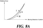
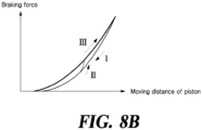
- FIGS. 8A and 8B are graph depicting a transition interval function according to an embodiment of the present disclosure.
- the transition section means a section in which the braking force is transferred from any one of the rising section and the falling section to another section as the moving direction of the piston 131 is changed.
- FIG. 8A is a graph showing a path in which the braking force is changed according to the moving distance of the piston when the piston moves toward the wheel disc and then moves in the opposite direction to the wheel disc.
- the magnitude of the braking force according to the moving distance of the piston is changed along the path I while the piston moving toward the wheel disc, along the path II in the transition section after the direction is changed, and along the path III after the transition section.
- FIG. 8B is a graph showing a path in which the braking force is changed according to the moving distance of the piston when the piston moves in the opposite direction to the wheel disc and then moves toward the wheel disc.
- the magnitude of the braking force according to the moving distance of the piston is changed along the path I while the piston moving in the opposite direction to the wheel disc, along the path II in the transition section after the direction is changed, and along the path III after the transition section.
- the function value of the transition section function has a value that is greater than the function value of the falling section function f r (see FIG. 6 ) and is smaller than the function value of the rising section function f a (see FIG. 6 ). If the braking force calculation unit 166 calculates the braking force only by the rising section function f a (see FIG. 6 ) or the falling section function f r (see FIG. 6 ), a difference occurs between the braking force calculated using the braking force calculation unit 166 in the transition section and an actual braking force. Therefore, the electro-mechanical brake according to an embodiment of the present disclosure includes a transition section function data generating unit 164 that generates transition section function data.
- the transition section function data generated by the transition section function data generating unit 164 may be determined based on the wear amount of the brake pad 140.
- the transition section function data generating unit 164 may include a memory (not shown) that stores the transition section function data on the transition section. After the transition section function data is experimentally obtained, the data may be converted into a Look-Up Table (LUT) form and stored in the memory. The function data stored in the memory is called and used to calculate the braking force.
- the transition section function data generating unit 164 according to another embodiment of the present disclosure includes a transition section function data calculation unit (not shown) that calculates the transition section function based on the position of the piston 131 in real time to generate a function.
- the braking force calculation unit 166 calculates the braking force based on the position of the piston 131.
- the braking force may be calculated by putting the position of the piston 131 into the rising section function f a (see FIG. 6 ).
- the braking force is calculated using the transition section function in the position section of the piston 131 in which the transition section function value is smaller than the value of the rising section function f a (see FIG. 6 ).
- the braking force calculation unit 166 follows a function with a smaller function value among the transition section function and the rising section function f a (see FIG. 6 ) to calculate the braking force.
- the braking force may be calculated by putting the position of the piston 131 into the falling section function f r (see FIG. 6 ). However, when the piston 131 moves toward the wheel disc 150 and then moves to the opposite side of the wheel disc 150, the braking force is calculated using the falling section function f r (see FIG. 6 ) in the position section of the piston 131 in which the transition section function value is smaller than the value of the falling section function f r (see FIG. 6 ).
- the braking force calculation unit 166 follows a function with a larger function value among the transition section function and the falling section function f r (see FIG. 6 ) to calculate the braking force.
- FIG. 9 is a graph showing a ramp-up interval function, a ramp-down interval function, and a transition interval function according to an embodiment of the present disclosure.
- the transition section functions f t,1 and f t,2 may have a positive slope.
- the differential value of the transition section functions f t,1 and f t,2 may be greater than the differential value of the rising section function f a (see FIG. 9 ) and the differential value of the falling section function f r (see FIG. 9 ).
- the transition section functions f t,1 and f t,2 may be linear functions with positive slopes.
- a plurality of transition section functions f t,1 and f t,2 present between the rising section and the falling section may be linear functions having the same slope.
- the control unit 160 determines the wear degree of the brake pad 140 by measuring a distance between the contact point and the lowest point of the stroke of the piston 131.
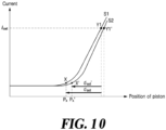
- FIG. 10 is a graph depicting how braking force changes with respect to the position of a piston in the case of abrasion of a brake pad according to an embodiment of the present disclosure.
- S1 is a graph showing the intensity of current according to the position of the piston 131.
- S2 is a graph showing the intensity of current according to the position of the piston 131 when the brake pad 140 is further worn compared to that of S1.
- the hysteresis characteristics are not shown so as to clearly represent the graph between the position of the piston 131 and the braking force according to the wear degree of the brake pad 140.
- the following description is applied to all of the rising section function f a (see FIG. 6 ), the transition section function, and the falling section function f r (see FIG. 6 ).
- a preset distance which is a distance from the first position to the second position, should be differently set from d set to d set '. That is, the preset distance should be differently set depending on the wear degree of the brake pad 140.
- the control unit 160 may measure the absolute distance of the contact point X, and determine that the wear degree of the brake pad 140 increases as the absolute distance increases.
- the absolute distance of the contact point X means the operating distance from the lowest point of the stroke to the contact point.
- the control unit 160 may find and apply the value of d set ' according to the wear degree of the brake pad 140.
- the variation of d set according to the wear degree of the brake pad 140 may be experimentally obtained, converted into the Look-Up Table (LUT) form, and stored in the memory of the control unit 160. That is, the control unit 160 may calculate the absolute distance of the brake pad 140 to determine the wear degree of the brake pad 140, and convert the value of d set into the value of d set ' to estimate the contact point X' of the worn brake pad 140.
- LUT Look-Up Table
- the electro-mechanical brake determines the rising section function f a (see FIG. 6 ), the transition section function, and the falling section function f r (see FIG. 6 ) based on the wear amount of the brake pad 140.
- the hysteresis data storage unit 161 stores data on a plurality of rising section functions f a (see FIG. 6 ) determined based on the wear amount of the brake pad 140 and data on a plurality of falling section functions f r (see FIG. 6 ) determined based on the wear amount of the brake pad 140.
- the wear amount of the brake pad 140 may be determined by measuring the distance from the lowest point of the stroke of the piston 131 to positions P x and P x' of the piston 131 when the brake pad 140 starts to contact the wheel disc 150.
- the contact point calculation unit 165 may calculate and/or calibrate a contact point based on the position of the piston 131 detected by the position detection unit 170 and the value of current applied to the motor 120 detected by the current detection unit 180. Specifically, the contact point calculation unit 165 may calculate and/or calibrate the contact point based on the position of the piston 131 detected by the position detection unit 170 with respect to a plurality of specified current values and the position of the piston of the piston 131 measured with respect to the plurality of specified current values. In this way, the contact point may be accurately calculated and/or calibrated by using data from a plurality of points in calculating and/or calibrating the contact point. Also, it is possible to calculate force more accurately, such as clamping force or braking force, and to reduce variation in calculation between samples.
- the plurality of specified current values may be determined based on a current applied to the motor 120 and a force measured with respect to the current applied to the motor 120.
- the force may refer to a clamping force or a braking force.
- the plurality of specified current values may be current values in an area where the force changes linearly with the current applied to the motor 120 within a predetermined margin of error - that is, current values in an area where the force changes at a relatively constant rate. Using the current values in such an area, the contact point may be calculated and/or calibrated more accurately, and as a result, the force may be accurately calculated.
- a current for the motor 120 used to calculate and/or calibrate the contact point may be filtered by the filter, but a time delay may occur due to the filtering.
- the motor 120 may be controlled (e.g., ramping) by using the motor controller 167 so that the piston 131 is moved at a constant speed for a preset amount of time in order to calculate and/or calibrate the contact point, which generates the same amount of time delay across the entire range, thereby solving the problem of time delay due to filtering.
- the contact point calculation unit 165 may calculate and/or calibrate a contact point for each vehicle wheel, especially, front and rear vehicle wheels.
- Each vehicle wheel may vary in the value of current required for the motor 120 to brake, the position of the piston 131, clamping force, braking force, stiffness, and so forth.
- the electro-mechanical brake 100 is able to accurately calculate and/or calibrate the contact point despite variations that may be generated between the vehicle wheels and as a result, allowing for accurate calculation of force.
- the electro-mechanical brake 100 may further include a stiffness calibration unit (not shown).
- the stiffness calibration unit may calibrate the stiffness of a caliper used for EMB based on the position of the piston 131 and the value of current applied to the motor 120.
- the stiffness refers to the slope of a force-position graph such as shown in FIG. 6 , that is, the rate of change of force with respect to position of the piston 131.
- the stiffness may refer to the slope of a current-position graph, such as shown in FIG. 4 , since the current applied to the motor 120 of the electro-mechanical brake 100 is proportional to the force.
- the stiffness calibration unit may calculate a stiffness weight based on a current detected by the current detection unit 180 with respect to a specified position of the piston 131 and a current measured with respect to the specified position of the piston 131, and may calibrate the stiffness of the caliper based on the stiffness weight.
- the stiffness calibration unit calibrates the stiffness based on the value of current detected by the current detection unit 180 with respect to a specified position of the piston 131 and the value of current measured with respect to the specified position of the piston 131, it is possible to accurately calculate the force of the electro-mechanical brake 100 without a force sensor such as a load sensor.
- the stiffness calibration unit may calibrate stiffness based on information on the contact point calibrated and/or calibrated by the contact point calculation unit 165.
- the calculations are done in the reverse order. That is, the rate of change of position of the contact point may be calculated by using Equation 2 first and then used to calculate and/or calibrate the contact point, thereby allowing for more accurate calculation and/or calibration of the contact point.
- FIG. 11 is a flowchart of a control method of an electro-mechanical brake according to an embodiment of the present disclosure.
- the position detection unit detects the position of the piston (S1110).
- the position detection unit 170 detects the position of the piston 131 which is moved by driving the motor 120.
- the position detection unit 170 may transmit information on the position of the piston 131 to the contact point calculation unit 165, the stiffness calibration unit, and so on.
- the current detection unit detects the value of current applied to the motor (S1120).
- the current detection unit 180 detects the value of current applied to the motor 120 of the electro-mechanical brake 100.
- the current detection unit 180 may transmit information on the value of current applied to the motor 120 to the contact point calculation unit 165, the stiffness calibration unit, and so on.
- the contact point calculation unit calculates a contact point based on the position of the piston and the value of current applied to the motor (S1130).
- the contact point calculation unit may receive information on the position of the piston 131 from the position detection unit 170.
- the contact point calculation unit 165 may receive information on the value of current applied to the motor 120 from the current detection unit 180.
- the contact point calculation unit 165 may calculate the contact point based on the position of the piston 131 detected by the position detection unit 170 and the value of current applied to the motor 120.
- the contact point calculation unit 165 may calculate the contact point based on the position of the piston 131 detected by the position detection unit 170 with respect to a plurality of specified current values and the position of the piston 131 measured with respect to the plurality of specified current values.
- the plurality of specified current values may be determined based on a current applied to the motor 120 and a force measured with respect to the current applied to the motor 120.
- the plurality of specified current values may be current values in an area where the force changes linearly with the current applied to the motor 120 within a predetermined margin of error - that is, current values in an area where the force changes at a relatively constant rate.
- the contact point calculation unit 165 may calculate and/or calibrate a contact point for each vehicle wheel, especially, front and rear vehicle wheels. By calculating and/or calibrating a contact point for each vehicle wheel, the contact point may be accurately calculated despite variations that may be generated between the vehicle wheels and as a result, allowing for accurate calculation of force.
- the contact point calculation unit calibrates the contact point based on the position of the piston and the value of current applied to the motor (S1140).
- the contact point calculation unit 165 may calibrate the contact point based on the position of the piston 131 detected by the position detection unit 170 and the value of current applied to the motor 120 detected by the current detection unit 180.
- the contact point calculation unit may calibrate the contact point based on the position of the piston 131 detected by the position detection unit 170 with respect to a plurality of specified current values and the position of the piston 131 measured with respect to the plurality of specified current values.
- the plurality of specified current values may be determined based on a current applied to the motor 120 and a force measured with respect to the current applied to the motor 120.
- the contact point calculation unit 165 may calculate a contact point for each vehicle wheel, especially, front and rear vehicle wheels.
- the stiffness calibration unit calibrates the stiffness of a caliper based on the position of the piston and the value of current applied to the motor (S1150).
- the stiffness calibration unit may calibrate the stiffness based on the position of the piston 131 and the value of current applied to the motor 120.
- the stiffness calibration unit may calculate a stiffness weight based on the value of current detected by the current detection unit 180 with respect to a specified position of the piston 131 and the value of current measured with respect to the specified position of the piston 131, and may calibrate the stiffness based on the stiffness weight.
- the stiffness weight may be calculated using Equation 1, and the specified position of the piston 131 may be plural.
- the stiffness calibration unit may calibrate the stiffness of the caliper based on information on the contact point calculated by the contact point calculation unit 165.
- the stiffness calibration unit may calibrate the stiffness based on the rate of change of position of the contact point which is calculated by Equation 2.
- the stiffness may be calibrated based on the rate of change of position of the contact point which is calculated by using the position of the piston 131 and the current applied to the motor 120.
- the calculations are done in the reverse order. That is, the rate of change of position of the contact point may be calculated by using Equation 2 first and then used to calculate and/or calibrate the contact point, thereby allowing for more accurate calculation and/or calibration of the contact point.
- an electro-mechanical brake is able to estimate force based on a current applied to a motor and the position of a piston.
- an electro-mechanical brake is able to accurately calculate force by calculating and/or calibrating a contact point based on a current applied to a motor and the position of a piston.
- an electro-mechanical brake is able to accurately calculate force by calibrating the stiffness of a caliper and an abrasion of pads based on a current applied to a motor and the position of a piston.
- an electro-mechanical brake is able to accurately calculate braking force based on a hysteresis characteristic of the braking force relative to the position of a piston.
- Various implementations of the units, systems and techniques described herein can be realized in digital electronic circuitry, integrated circuitry, a field programmable gate array (FPGA), an application specific integrated circuit (ASIC), computer hardware, firmware, software, and/or combinations thereof. These various implementations may include being implemented in one or more computer programs executable on a programmable system.
- the programmable system includes at least one programmable processor (which may be a special purpose processor or a general-purpose processor) coupled to receive data and instructions from, and transmit data and instructions to, a storage system, at least one input device, and at least one output device.
- Computer programs also known as programs, software, software applications or code
- the computer-readable recording medium includes all kinds of recording devices that store data readable by a computer system.
- a computer-readable recording medium may be a non-volatile or non-transitory medium such as ROM, CD-ROM, a magnetic tape, a floppy disk, a memory card, a hard disk, a magnetic optical disk, a storage device, and the like. Also, it may further include a transitory medium such as a data transmission medium. Further, the computer-readable recording medium may be distributed to computer systems connected via a network so that computer-readable code can be stored and executed in a distributed manner.
- the computer includes a programmable processor, a data storage system (including volatile memory, nonvolatile memory, or any other type of storage system or a combination thereof), and at least one communication interface.
- the programmable computer may be one of a server, a network device, a set-top box, an embedded device, a computer expansion module, a personal computer, a laptop, a personal data assistant (PDA), a cloud computing system, and a mobile device.
- PDA personal data assistant
Landscapes
- Engineering & Computer Science (AREA)
- Mechanical Engineering (AREA)
- Transportation (AREA)
- General Engineering & Computer Science (AREA)
- Braking Arrangements (AREA)
- Braking Systems And Boosters (AREA)
Abstract
Description
- This application claims priority to and the benefit of
Korean Patent Application No. 10-2022-0058472, filed on May 12, 2022 - The present disclosure relates to an electro-mechanical brake and a control method thereof.
- The content described in this section merely provides the background information on the present disclosure and does not constitute the prior art.
- An Electro-Mechanical Brake (EMB) is being widely used. The electro-mechanical brake was developed as an Electronic Parking Brake (EPB), but the field of use of the brake is expanding to a main brake which substitutes for a conventional hydraulic brake. The EMB is a device in which an actuator driven by a motor is mounted on a brake caliper, so that a vehicle is directly braked by a motor driving force without a medium such as brake fluid. Since the EMB has a mechanism similar to that of the Electronic Parking Brake (EPB) but is mainly used for main braking unlike the EPB, the EMB requires higher braking response and operation durability than those of the EPB. Further, the electro-mechanical brake may be simpler in structure, be higher in braking response speed, and be more precisely controlled compared to the hydraulic brake, thereby improving braking stability.
- An electro-mechanical brake with a force sensor mounted to it is able to accurately measure clamping force. However, mounting a force sensor to an electro-mechanical brake complicates the design and raises the manufacturing cost. The mounting of the sensor also increases the size of the electro-mechanical brake.
- To solve the problem of the rise in manufacturing cost and the problem of the increase in equipment size, a current sensor may be used instead of a force sensor to estimate clamping force. The electro-mechanical brake may be designed in such a way that the current sensor measures a current applied to a motor that generates braking force and estimates clamping force based on the measured current. However, a problem with the estimating of clamping force by measuring a current applied to the motor is that this method has lower accuracy compared to using a force sensor, due to a measurement noise from the current sensor.
-
FIGS. 12A ,12B and12C are view showing a construction of a conventional electro-mechanical brake. - Referring to
FIGS. 12A to 12C , the electro-mechanical brake includes a wheel disc 12_c, a pair of brake pads 12_b disposed on both sides of the wheel disc 12_c, and a piston 12a configured to push the brake pads 12_b towards the wheel disc 12_c. The further the piston 12_a moves towards the wheel disc 12_c, the greater the braking force. Still, even if the relative positions of the piston 12_a and the brake pads 12_b are the same, the braking force varies with the movement path of the piston 12_a. That is, the braking force relative to the position of the piston 12_a has a hysteresis characteristic. Therefore, accurate estimation of braking force requires consideration of the movement path of the piston 12_a. - According to at least one aspect, the present disclosure provides an electro-mechanical brake comprising a piston to push a brake pad towards a wheel disc by driving a motor in a vehicle; a position detection unit that detects a position of the piston based on a plurality of specified current values; a current detection unit that detects a value of current applied to the motor; and a contact point calculation unit that calculates a contact point, which is where the piston is located when the brake pad starts to come into contact with the wheel disc, based on the position of the piston and the value of the current applied to the motor, or based on a first position of the piston detected by the position detection unit with respect to a plurality of specified current values and a second position of the piston measured with respect to the plurality of specified current values.
- According to another aspect, the present disclosure provides a control method of an electro-mechanical brake comprising a piston to push a brake pad towards a wheel disc by driving a motor in a vehicle, the control method comprising: a position detection process including detecting, by a position detection unit, a position of the piston; a current detection process including detecting, by a current detection unit, a value of current applied to the motor; and a contact point calculation process including calculating, by a contact point calculation unit, a contact point, which is where the piston is located when the brake pad starts to come into contact with the wheel disc, is calculated based on the position of the piston and the value of current applied to the motor, or based on a first position of the piston detected by the position detection unit with respect to a plurality of specified current values and a second position of the piston measured with respect to the plurality of specified current values.
-
-
FIG. 1 is a view showing a construction of an electro-mechanical brake according to an embodiment of the present disclosure. -
FIGS. 2A to 2C are view showing an operating state of an electro-mechanical brake according to an embodiment of the present disclosure. -
FIG. 3 is a graph of the current versus moving distance of a braking pad according to an embodiment of the present disclosure. -
FIG. 4 is a graph depicting a method of estimating a contact point of an electro-mechanical brake according to an embodiment of the present disclosure. -
FIG. 5 is a graph showing a motor control timing for detecting a contact point of an electro-mechanical brake according to an embodiment of the present disclosure. -
FIG. 6 is a graph showing the amount of braking force with respect to the position and moving direction of a piston according to an embodiment of the present disclosure. -
FIG. 7 is a graph depicting a process of calculating the braking force of an electro-mechanical brake according to an embodiment of the present disclosure. -
FIGS. 8A and8B are graph depicting a transition interval function according to an embodiment of the present disclosure. -
FIG. 9 is a graph showing a ramp-up interval function, a ramp-down interval function, and a transition interval function according to an embodiment of the present disclosure. -
FIG. 10 is a graph depicting how braking force changes with respect to the position of a piston in the case of abrasion of a brake pad according to an embodiment of the present disclosure. -
FIG. 11 is a flowchart of a control method of an electro-mechanical brake according to an embodiment of the present disclosure. -
FIGS. 12A ,12B and12C are view showing a construction of a conventional electro-mechanical brake. - An electro-mechanical brake according to an embodiment of the present disclosure is able to estimate force based on a current applied to a motor and the position of a piston.
- An electro-mechanical brake according to an embodiment of the present disclosure is able to accurately calculate force by calculating and/or calibrating a contact point based on a current applied to a motor and the position of a piston.
- An electro-mechanical brake according to an embodiment of the present disclosure is able to accurately calculate force by calibrating the stiffness of a caliper and an abrasion of pads based on a current applied to a motor and the position of a piston.
- An electro-mechanical brake according to an embodiment of the present disclosure is able to accurately calculate braking force based on a hysteresis characteristic of the braking force relative to the position of a piston.
- The aspects of the present disclosure are not limited to the foregoing, and other aspects not mentioned herein will be able to be clearly understood by those skilled in the art from the following description.
- Hereinafter, some exemplary embodiments of the present disclosure will be described in detail with reference to the accompanying drawings. In the following description, like reference numerals preferably designate like elements, although the elements are shown in different drawings. Further, in the following description of some embodiments, a detailed description of known functions and configurations incorporated therein will be omitted for the purpose of clarity and for brevity.
- Additionally, various terms such as first, second, A, B, (a), (b), etc., are used solely to differentiate one component from the other but not to imply or suggest the substances, order, or sequence of the components. Throughout this specification, when a part 'includes' or 'comprises' a component, the part is meant to further include other components, not to exclude thereof unless specifically stated to the contrary. The terms such as 'unit', 'module', and the like refer to one or more units for processing at least one function or operation, which may be implemented by hardware, software, or a combination thereof.
-
FIG. 1 is a view showing a construction of an electro-mechanical brake according to an embodiment of the present disclosure. - Referring to
FIG. 1 , the electro-mechanical brake according to an embodiment of the present disclosure includes all or some of awheel disc 150, abrake pad 140, apiston 131, amotor 120, acurrent detection unit 180, aposition detection unit 170, a hysteresisdata storage unit 161, acalculation unit 162, a past statedata storage unit 163, a transition section functiondata generating unit 164, a contactpoint calculation unit 165, a brakingforce calculation unit 166, and amotor controller 167. - The
wheel disc 150 is coupled to a wheel of a vehicle. Thewheel disc 150 is rotated along with the wheel of the vehicle. By restricting the rotation of thewheel disc 150, the vehicle may be braked. Thebrake pad 140 is disposed on a side of thewheel disc 150. Thepiston 131 is configured to push thebrake pad 140 toward thewheel disc 150 by driving themotor 120. As thepiston 131 presses thebrake pad 140 toward thewheel disc 150, a frictional force is generated between thebrake pad 140 and thewheel disc 150. Due to the frictional force generated between thebrake pad 140 and thewheel disc 150, the rotation of thewheel disc 150 is restricted. Themotor 120 supplies power to thepiston 131. - A process in which the
piston 131 receives power from themotor 120 and then is driven will be described. Adriving gear 134 is rotated along with arotating shaft 121 of themotor 120 by driving themotor 120. Thedriving gear 134 engages with a drivengear 133. When thedriving gear 134 rotates, the drivengear 133 is also rotated. The drivengear 133 is coupled to ascrew shaft 132. Thescrew shaft 132 rotates in conjunction with the rotation of the drivengear 133. A screw thread is formed on the outer circumference of thescrew shaft 132. A screw groove having a shape corresponding to that of the screw thread of thescrew shaft 132 is formed on the inner circumference of thepiston 131. If thescrew shaft 132 is rotated along with the drivengear 133, thepiston 131 moves rectilinearly while being fastened to or unfastened from thescrew shaft 132. If thepiston 131 moves rectilinearly toward thewheel disc 150, thebrake pad 140 is pushed toward thewheel disc 150 by thepiston 131. - The
position detection unit 170 detects the position of thepiston 131. The position of thepiston 131 represents a distance from a lowest point of a stroke of thepiston 131 to thepiston 131. Here, the stroke lowest point refers to the position of thebrake pad 140 when thebrake pad 140 is maximally spaced apart from thewheel disc 150. - The
position detection unit 170 may include an angle sensor. The angle sensor measures the angular displacement of therotating shaft 121 of themotor 120. Theposition detection unit 170 may calculate the rectilinear moving distance of thepiston 131 using the angular displacement of the rotating shaft 21 sensed by the angle sensor. The rectilinear moving distance of thepiston 131 according to the rotating angle of themotor 120 may vary depending on the design of the electro-mechanical brake. For instance, the electro-mechanical brake may be designed such that the rectilinear moving distance of thepiston 131 is 1 mm while therotating shaft 121 of themotor 120 is rotated at 360 degrees. -
FIGS. 2A to 2C are view showing an operating state of an electro-mechanical brake according to an embodiment of the present disclosure. - Referring to
FIG. 2A , when thebrake pad 140 is spaced apart from thewheel disc 150, no braking force is generated. Here, the braking force is the force for braking the vehicle. When thepiston 131 pushes thebrake pad 140 so that thebrake pad 140 contacts thewheel disc 150 as shown inFIG. 2B , frictional force is generated between thebrake pad 140 and thewheel disc 150. The frictional force generated between thebrake pad 140 and thewheel disc 150 acts as the braking force. The position of thepiston 131 where thebrake pad 140 starts to contact thewheel disc 150 is referred to as a contact point. As shown inFIG. 2C , when thepiston 131 passes through the contact point and moves toward thewheel disc 150, the force of thepiston 131 pressing thebrake pad 140 is increased. Here, the force of thepiston 131 pressing thebrake pad 140 is referred to as clamping force. If the clamping force increases, the frictional force generated between thebrake pad 140 and thewheel disc 150 increases. That is, the braking force increases. - The electro-mechanical brake according to an embodiment of the present disclosure may estimate the clamping force not by using a load sensor but by using a current sensor and a position sensor.
- The
position detection unit 170 may precisely measure the position of thepiston 131 using the angle sensor. However, since the contact point varies depending on the wear state of thebrake pad 140, the position of the contact point cannot be recognized only by the position of thepiston 131. If the contact point is not recognized, it is difficult to precisely estimate the clamping force according to the position of thepiston 131. - The
current detection unit 180 detects the value of current flowing through themotor 120. Thecontrol unit 160 feeds back the current value detected by thecurrent detection unit 180 to control themotor 120. The electro-mechanical brake device according to an embodiment of the present disclosure identifies the position of the contact point using current control. -
FIG. 3 is a graph of the current versus moving distance of a braking pad according to an embodiment of the present disclosure. - Referring to
FIG. 3 , the value of current applied to themotor 120 increases in proportion to the position of thepiston 131. The value of current applied to themotor 120 may increase in proportion to clamping force. However, it is difficult to precisely calculate clamping force because measurements by a current sensor have a large margin of error. Referring toFIG. 3 , if the current sensor detects a value ix to be a contact point, a large margin of error (e) is generated due to a measurement noise in the current sensor. Thecurrent detection unit 180 according to an embodiment of the present disclosure may include a current sensor that measures a current applied to themotor 120 and a filter (not shown) that removes noise from the measured current. Here, the filter may be a low-pass filter. Using the current sensor alone, a current value corresponding to a contact point may be measured from a plurality of points due to a measurement noise. The contactpoint calculation unit 165 may calculate a contact point by using a current from which noise is removed by the filter. - In removing a measurement noise in the current sensor using the filter, a time delay may occur. However, this may be solved by moving the
piston 131 at a constant speed over time so that the same amount of time delay occurs across the entire range. -
FIG. 4 is a graph depicting a method of estimating a contact point of an electro-mechanical brake according to an embodiment of the present disclosure. - Referring to
FIG. 4 , the horizontal axis of the graph represents the position of thepiston 131, while the vertical axis thereof represents the value of current flowing through themotor 120. As it proceeds to the right on the horizontal axis of the graph, a gap g (seeFIG. 1 ) between thebrake pad 140 and thewheel disc 150 is reduced. - The current value of the
motor 120 is maintained at a substantially constant value in a section before the contact point X, but the current value is non-linearly increased in a non-linear section a shown inFIG. 4 after the contact point. If the operating distance is further increased past the non-linear section a, the current value is linearly increased in a linear section b shown inFIG. 4 . Here, the linear section b refers to a section in which the current value detected using thecurrent detection unit 180 is linearly changed within a predetermined error range for the position of thepiston 131. - The position of the
piston 131 when thecurrent detection unit 180 detects the first current value iset is defined as a first position Y1. The first current value iset that is a preset value may be a current value on the linear section b. When the first current value iset is the current value on the linear section b, the error range occurring in the linear section b is narrower than the error range e occurring in the non-linear section a, so that the contact point can be more accurately calculated. - The
control unit 160 includes all or some of a hysteresisdata storage unit 161, acalculation unit 162, a past statedata storage unit 163, a transition section functiondata generating unit 164, a contactpoint calculation unit 165, a brakingforce calculation unit 166, and amotor controller 167. - The contact
point calculation unit 165 calculates the contact point X based on the first position Y1 that is the position of thepiston 131 when the first current value is detected using thecurrent detection unit 180. The contactpoint calculation unit 165 calculates a second position spaced apart from the first position Y1 by a preset distance dset to an opposite side of thewheel disc 150 as the contact point X. The value of the preset distance dset that is an experimentally measured value may vary depending on the specification of the electro-mechanical brake. Thecontrol unit 160 may determine the relative positions of thebrake pad 140 and thewheel disc 150 and the size of an air gap using the position sensor, based on the determined contact point X. - The
motor controller 167 drives themotor 120 for a preset time when the vehicle is stopped, thus moving thepiston 131 toward thewheel disc 150. Themotor controller 167 may drive themotor 120 for a preset time when the vehicle is parked and the door of the vehicle is opened, thus moving thepiston 131 toward thewheel disc 150. If the door is opened while the vehicle is parked, themotor controller 167 may drive themotor 120 at a preset angular speed for a preset time. Based on data on the current value for the position of thepiston 131 collected for a preset time, the contactpoint calculation unit 165 may calculate the contact point X. - When a driver presses a brake pedal before the preset time has elapsed, the
motor controller 167 drives themotor 120 at a preset angular speed for a preset time after the door of the vehicle is opened, thus moving thepiston 131 toward thewheel disc 150. Themotor controller 167 controls themotor 120 to generate a braking force corresponding to a braking signal immediately after a preset time has elapsed. -
FIG. 5 is a graph showing a motor control timing for detecting a contact point of an electro-mechanical brake according to an embodiment of the present disclosure. - Referring to
FIG. 5 , if the door is opened while the vehicle is stopped, themotor controller 167 drives themotor 120 at a predetermined angular speed for about 2 seconds to move thepiston 131 toward thewheel disc 150. In the present disclosure, an operation in which themotor controller 167 drives themotor 120 at a predetermined angular speed for a preset time is referred to as ramp driving. The contactpoint calculation unit 165 identifies the contact point based on the current value data for the position of thepiston 131 acquired by the ramp driving. - If a driver presses the pedal before the ramp driving is finished, the
motor controller 167 controls themotor 120 to generate the braking force corresponding to the braking signal that is input using the brake pedal immediately after the ramp driving is finished. The ramp driving is performed while the vehicle is parked. Thus, even if the braking force that does not correspond to the braking signal generated by the driver is generated during the ramp driving, the driver cannot see that the braking force that does not correspond to the braking signal is generated. - The
motor controller 167 controls themotor 120 so that the electro-mechanical brake generates a demand braking force based on the braking force calculated by the brakingforce calculation unit 166. -
FIG. 6 is a graph showing the amount of braking force with respect to the position and moving direction of a piston according to an embodiment of the present disclosure. - Referring to
FIG. 6 , the horizontal axis of the graph represents the position of thepiston 131. When thepiston 131 is at the lowest point of the stroke, the position of thepiston 131 is set to 0. The vertical axis of the graph represents the braking force. The braking force is not determined only by the position of thepiston 131. Even if thepiston 131 is at the same position, the braking force when thepiston 131 moves toward thewheel disc 150 is different from the braking force when thepiston 131 moves to the opposite side of thewheel disc 150. Therefore, in order to accurately estimate the braking force, it is necessary to consider the position of thepiston 131 as well as the moving path of thepiston 131. In the present disclosure, a function for a rising section in which the braking force is increased as thepiston 131 moves toward thewheel disc 150 is referred to as a rising section function fa (seeFIG. 6 ), and a function for a falling section in which the braking force is reduced as thepiston 131 moves to the opposite side of thewheel disc 150 is referred to as a falling section function fa (seeFIG. 6 ). -
FIG. 7 is a graph depicting a process of calculating the braking force of an electro-mechanical brake according to an embodiment of the present disclosure. - Referring to
FIG. 7 , the vertical axis of the graph ofFIG. 7 represents the position of thepiston 131. When thepiston 131 is at the lowest point of the stroke, the position of thepiston 131 is set to 0. The horizontal axis of the graph represents an elapsed time. - The moving state of the
piston 131 of the electro-mechanical brake may be divided into four states. Instate ①, thepiston 131 moves toward thewheel disc 150. That is, a differential value of the position of thepiston 131 with respect to time is a positive number. Instate ③, the position of thepiston 131 with time is reduced. That is, the differential value of the position of thepiston 131 with respect to time is a negative number. Instate ② and state ④, the position of thepiston 131 is not changed. In other words, the differential value of the position of thepiston 131 with respect to time is 0.State ② and state ④ are divided depending on the moving state of thepiston 131 just before thepiston 131 is stopped. If the differential value of the position of thepiston 131 is the positive number before thepiston 131 is stopped, this may be defined asstate ②. If the differential value of the position of thepiston 131 is the negative number before thepiston 131 is stopped, this may be defined as state ④. When the moving state of thepiston 131 isstate ① orstate ②, the braking force for the position of thepiston 131 is determined according to the rising section function. When the moving state of thepiston 131 isstate ③ or state ④, the braking force for the position of thepiston 131 is determined according to the falling section function. - The hysteresis
data storage unit 161 stores data on the rising section function fa (seeFIG. 6 ) for the rising section, and data on the falling section function fr (seeFIG. 6 ) for the falling section. - The
calculation unit 162 calculates the differential value of the position of thepiston 131 with respect to time. The past statedata storage unit 163 stores data on a preceding section corresponding to the position of apreceding piston 131. - The braking
force calculation unit 166 may calculate the braking force based on the differential value of the position of thepiston 131 and data on the preceding section. The brakingforce calculation unit 166 follows the rising section function to calculate the braking force when the differential value of the position of thepiston 131 with respect to time is the positive number. When the differential value of the position of thepiston 131 with respect to time is the negative number, the braking force calculation unit follows the falling section function to calculate the braking force. If the differential value of the position of thepiston 131 with respect to time is 0 and the section corresponding to the position of thepreceding piston 131 is the rising section, the braking force calculation unit follows the rising section function to calculate the braking force. If the differential value of the position of thepiston 131 with respect to time is 0 and the section corresponding to the position of thepreceding piston 131 is the falling section, the braking force calculation unit follows the falling section function to calculate the braking force. Thus, the braking force may be calculated using an appropriate function according to the moving state of thepiston 131. By calculating the braking force using the appropriate function, the braking force may be more accurately calculated. -
FIGS. 8A and8B are graph depicting a transition interval function according to an embodiment of the present disclosure. - Referring to
FIG. 8 , when the moving direction of thepiston 131 is switched at a position other than a highest point or a lowest point of the braking force, the actual braking force is continuously changed along a path II that follows the transition section function. Here, the transition section means a section in which the braking force is transferred from any one of the rising section and the falling section to another section as the moving direction of thepiston 131 is changed. -
FIG. 8A is a graph showing a path in which the braking force is changed according to the moving distance of the piston when the piston moves toward the wheel disc and then moves in the opposite direction to the wheel disc. - When the piston moves toward the wheel disc and then moves in the opposite direction to the wheel disc, the magnitude of the braking force according to the moving distance of the piston is changed along the path I while the piston moving toward the wheel disc, along the path II in the transition section after the direction is changed, and along the path III after the transition section.
-
FIG. 8B is a graph showing a path in which the braking force is changed according to the moving distance of the piston when the piston moves in the opposite direction to the wheel disc and then moves toward the wheel disc. - When the piston moves in the opposite direction to the wheel disc and then moves toward the wheel disc, the magnitude of the braking force according to the moving distance of the piston is changed along the path I while the piston moving in the opposite direction to the wheel disc, along the path II in the transition section after the direction is changed, and along the path III after the transition section.
- The function value of the transition section function has a value that is greater than the function value of the falling section function fr (see
FIG. 6 ) and is smaller than the function value of the rising section function fa (seeFIG. 6 ). If the brakingforce calculation unit 166 calculates the braking force only by the rising section function fa (seeFIG. 6 ) or the falling section function fr (seeFIG. 6 ), a difference occurs between the braking force calculated using the brakingforce calculation unit 166 in the transition section and an actual braking force. Therefore, the electro-mechanical brake according to an embodiment of the present disclosure includes a transition section functiondata generating unit 164 that generates transition section function data. - The transition section function data generated by the transition section function
data generating unit 164 may be determined based on the wear amount of thebrake pad 140. - The transition section function
data generating unit 164 according to an embodiment of the present disclosure may include a memory (not shown) that stores the transition section function data on the transition section. After the transition section function data is experimentally obtained, the data may be converted into a Look-Up Table (LUT) form and stored in the memory. The function data stored in the memory is called and used to calculate the braking force. On the other hand, the transition section functiondata generating unit 164 according to another embodiment of the present disclosure includes a transition section function data calculation unit (not shown) that calculates the transition section function based on the position of thepiston 131 in real time to generate a function. - The braking
force calculation unit 166 calculates the braking force based on the position of thepiston 131. - When the
piston 131 moves toward thewheel disc 150, the braking force may be calculated by putting the position of thepiston 131 into the rising section function fa (seeFIG. 6 ). However, when thepiston 131 moves to the opposite side of thewheel disc 150 and then moves toward thewheel disc 150, the braking force is calculated using the transition section function in the position section of thepiston 131 in which the transition section function value is smaller than the value of the rising section function fa (seeFIG. 6 ). In other words, when the moving direction of thepiston 131 is changed from the direction opposite to thewheel disc 150 to the direction of thewheel disc 150, the brakingforce calculation unit 166 follows a function with a smaller function value among the transition section function and the rising section function fa (seeFIG. 6 ) to calculate the braking force. - When the
piston 131 moves in the opposite direction to thewheel disc 150, the braking force may be calculated by putting the position of thepiston 131 into the falling section function fr (seeFIG. 6 ). However, when thepiston 131 moves toward thewheel disc 150 and then moves to the opposite side of thewheel disc 150, the braking force is calculated using the falling section function fr (seeFIG. 6 ) in the position section of thepiston 131 in which the transition section function value is smaller than the value of the falling section function fr (seeFIG. 6 ). In other words, when the moving direction of thepiston 131 is changed from the direction of thewheel disc 150 to the direction opposite to thewheel disc 150, the brakingforce calculation unit 166 follows a function with a larger function value among the transition section function and the falling section function fr (seeFIG. 6 ) to calculate the braking force. By configuring the electro-mechanical brake device in this way, it is possible to accurately estimate the braking force even when the moving direction of thepiston 131 is changed. -
FIG. 9 is a graph showing a ramp-up interval function, a ramp-down interval function, and a transition interval function according to an embodiment of the present disclosure. - Referring to
FIG. 9 , by reflecting the hysteresis characteristics of the braking force according to the position of thepiston 131, the transition section functions ft,1 and ft,2 may have a positive slope. At any position of thepiston 131, the differential value of the transition section functions ft,1 and ft,2 may be greater than the differential value of the rising section function fa (seeFIG. 9 ) and the differential value of the falling section function fr (seeFIG. 9 ). - In order to more easily generate the transition section functions ft,1 and ft,2, the transition section functions ft,1 and ft,2 may be linear functions with positive slopes. A plurality of transition section functions ft,1 and ft,2 present between the rising section and the falling section may be linear functions having the same slope.
- The
control unit 160 according to an embodiment of the present disclosure determines the wear degree of thebrake pad 140 by measuring a distance between the contact point and the lowest point of the stroke of thepiston 131. -
FIG. 10 is a graph depicting how braking force changes with respect to the position of a piston in the case of abrasion of a brake pad according to an embodiment of the present disclosure. - Referring to
FIG. 10 , S1 is a graph showing the intensity of current according to the position of thepiston 131. S2 is a graph showing the intensity of current according to the position of thepiston 131 when thebrake pad 140 is further worn compared to that of S1. InFIG. 10 , the hysteresis characteristics are not shown so as to clearly represent the graph between the position of thepiston 131 and the braking force according to the wear degree of thebrake pad 140. However, the following description is applied to all of the rising section function fa (seeFIG. 6 ), the transition section function, and the falling section function fr (seeFIG. 6 ). - If the
brake pad 140 is worn, the contact point moves from X to X'. That is, the contact point moves toward thewheel disc 150. As thebrake pad 140 is worn, the rigidity of thebrake pad 140 increases, so that the slope increases in the linear section b (seeFIG. 5 ). A first check point is moved from Y1 to Y1'. Thus, a preset distance, which is a distance from the first position to the second position, should be differently set from dset to dset'. That is, the preset distance should be differently set depending on the wear degree of thebrake pad 140. - The
control unit 160 may measure the absolute distance of the contact point X, and determine that the wear degree of thebrake pad 140 increases as the absolute distance increases. Here, the absolute distance of the contact point X means the operating distance from the lowest point of the stroke to the contact point. Thecontrol unit 160 may find and apply the value of dset' according to the wear degree of thebrake pad 140. The variation of dset according to the wear degree of thebrake pad 140 may be experimentally obtained, converted into the Look-Up Table (LUT) form, and stored in the memory of thecontrol unit 160. That is, thecontrol unit 160 may calculate the absolute distance of thebrake pad 140 to determine the wear degree of thebrake pad 140, and convert the value of dset into the value of dset' to estimate the contact point X' of theworn brake pad 140. - As the
brake pad 140 is worn, the differential value of the braking force function according to the position of thepiston 131 is increased at any point of thepiston 131. The electro-mechanical brake according to an embodiment of the present disclosure determines the rising section function fa (seeFIG. 6 ), the transition section function, and the falling section function fr (seeFIG. 6 ) based on the wear amount of thebrake pad 140. The hysteresisdata storage unit 161 according to an embodiment of the present disclosure stores data on a plurality of rising section functions fa (seeFIG. 6 ) determined based on the wear amount of thebrake pad 140 and data on a plurality of falling section functions fr (seeFIG. 6 ) determined based on the wear amount of thebrake pad 140. - The wear amount of the
brake pad 140 may be determined by measuring the distance from the lowest point of the stroke of thepiston 131 to positions Px and Px' of thepiston 131 when thebrake pad 140 starts to contact thewheel disc 150. - Referring back to
FIGS. 1 to 4 , contact point calculation and stiffness calibration for an electro-mechanical brake according to the present disclosure will be described in detail. - The contact
point calculation unit 165 may calculate and/or calibrate a contact point based on the position of thepiston 131 detected by theposition detection unit 170 and the value of current applied to themotor 120 detected by thecurrent detection unit 180. Specifically, the contactpoint calculation unit 165 may calculate and/or calibrate the contact point based on the position of thepiston 131 detected by theposition detection unit 170 with respect to a plurality of specified current values and the position of the piston of thepiston 131 measured with respect to the plurality of specified current values. In this way, the contact point may be accurately calculated and/or calibrated by using data from a plurality of points in calculating and/or calibrating the contact point. Also, it is possible to calculate force more accurately, such as clamping force or braking force, and to reduce variation in calculation between samples. - The plurality of specified current values may be determined based on a current applied to the
motor 120 and a force measured with respect to the current applied to themotor 120. Here, the force may refer to a clamping force or a braking force. The plurality of specified current values may be current values in an area where the force changes linearly with the current applied to themotor 120 within a predetermined margin of error - that is, current values in an area where the force changes at a relatively constant rate. Using the current values in such an area, the contact point may be calculated and/or calibrated more accurately, and as a result, the force may be accurately calculated. - As described above, a current for the
motor 120 used to calculate and/or calibrate the contact point may be filtered by the filter, but a time delay may occur due to the filtering. In this case, themotor 120 may be controlled (e.g., ramping) by using themotor controller 167 so that thepiston 131 is moved at a constant speed for a preset amount of time in order to calculate and/or calibrate the contact point, which generates the same amount of time delay across the entire range, thereby solving the problem of time delay due to filtering. - The contact
point calculation unit 165 may calculate and/or calibrate a contact point for each vehicle wheel, especially, front and rear vehicle wheels. Each vehicle wheel may vary in the value of current required for themotor 120 to brake, the position of thepiston 131, clamping force, braking force, stiffness, and so forth. By calculating and/or calibrating a contact point for each vehicle wheel, the electro-mechanical brake 100 according to the present disclosure is able to accurately calculate and/or calibrate the contact point despite variations that may be generated between the vehicle wheels and as a result, allowing for accurate calculation of force. - The electro-
mechanical brake 100 according to the present disclosure may further include a stiffness calibration unit (not shown). The stiffness calibration unit may calibrate the stiffness of a caliper used for EMB based on the position of thepiston 131 and the value of current applied to themotor 120. Here, the stiffness refers to the slope of a force-position graph such as shown inFIG. 6 , that is, the rate of change of force with respect to position of thepiston 131. Also, the stiffness may refer to the slope of a current-position graph, such as shown inFIG. 4 , since the current applied to themotor 120 of the electro-mechanical brake 100 is proportional to the force. - The stiffness calibration unit may calculate a stiffness weight based on a current detected by the
current detection unit 180 with respect to a specified position of thepiston 131 and a current measured with respect to the specified position of thepiston 131, and may calibrate the stiffness of the caliper based on the stiffness weight. Here, the stiffness weight may be calculated using the followingEquation 1, and the specified position of thepiston 131 may be plural.
- Since the stiffness calibration unit calibrates the stiffness based on the value of current detected by the
current detection unit 180 with respect to a specified position of thepiston 131 and the value of current measured with respect to the specified position of thepiston 131, it is possible to accurately calculate the force of the electro-mechanical brake 100 without a force sensor such as a load sensor. - The stiffness calibration unit may calibrate stiffness based on information on the contact point calibrated and/or calibrated by the contact
point calculation unit 165. The stiffness calibration unit may calibrate stiffness based on the rate of change of position of the contact point which is calculated by Equation 2:
piston 131 at the current time when the rate of change of position of the contact point is calculated, and (n-1) denotes the position of thepiston 131 at the previous time. It is possible to calibrate stiffness based on the rate of change of position of the contact point which is calculated by using the position of thepiston 131 and the current applied to themotor 120. - If the stiffness with respect to the position of the
piston 131 is relatively constant, for example, such as in the rear wheels of the vehicle, the calculations are done in the reverse order. That is, the rate of change of position of the contact point may be calculated by usingEquation 2 first and then used to calculate and/or calibrate the contact point, thereby allowing for more accurate calculation and/or calibration of the contact point. -
FIG. 11 is a flowchart of a control method of an electro-mechanical brake according to an embodiment of the present disclosure. - The position detection unit detects the position of the piston (S1110). The
position detection unit 170 detects the position of thepiston 131 which is moved by driving themotor 120. Theposition detection unit 170 may transmit information on the position of thepiston 131 to the contactpoint calculation unit 165, the stiffness calibration unit, and so on. - The current detection unit detects the value of current applied to the motor (S1120). The
current detection unit 180 detects the value of current applied to themotor 120 of the electro-mechanical brake 100. Thecurrent detection unit 180 may transmit information on the value of current applied to themotor 120 to the contactpoint calculation unit 165, the stiffness calibration unit, and so on. - The contact point calculation unit calculates a contact point based on the position of the piston and the value of current applied to the motor (S1130). The contact point calculation unit may receive information on the position of the
piston 131 from theposition detection unit 170. The contactpoint calculation unit 165 may receive information on the value of current applied to themotor 120 from thecurrent detection unit 180. The contactpoint calculation unit 165 may calculate the contact point based on the position of thepiston 131 detected by theposition detection unit 170 and the value of current applied to themotor 120. - Specifically, the contact
point calculation unit 165 may calculate the contact point based on the position of thepiston 131 detected by theposition detection unit 170 with respect to a plurality of specified current values and the position of thepiston 131 measured with respect to the plurality of specified current values. - The plurality of specified current values may be determined based on a current applied to the
motor 120 and a force measured with respect to the current applied to themotor 120. The plurality of specified current values may be current values in an area where the force changes linearly with the current applied to themotor 120 within a predetermined margin of error - that is, current values in an area where the force changes at a relatively constant rate. - The contact
point calculation unit 165 may calculate and/or calibrate a contact point for each vehicle wheel, especially, front and rear vehicle wheels. By calculating and/or calibrating a contact point for each vehicle wheel, the contact point may be accurately calculated despite variations that may be generated between the vehicle wheels and as a result, allowing for accurate calculation of force. - The contact point calculation unit calibrates the contact point based on the position of the piston and the value of current applied to the motor (S1140). The contact
point calculation unit 165 may calibrate the contact point based on the position of thepiston 131 detected by theposition detection unit 170 and the value of current applied to themotor 120 detected by thecurrent detection unit 180. - The contact point calculation unit may calibrate the contact point based on the position of the
piston 131 detected by theposition detection unit 170 with respect to a plurality of specified current values and the position of thepiston 131 measured with respect to the plurality of specified current values. The plurality of specified current values may be determined based on a current applied to themotor 120 and a force measured with respect to the current applied to themotor 120. - The contact
point calculation unit 165 may calculate a contact point for each vehicle wheel, especially, front and rear vehicle wheels. - The stiffness calibration unit calibrates the stiffness of a caliper based on the position of the piston and the value of current applied to the motor (S1150). The stiffness calibration unit may calibrate the stiffness based on the position of the
piston 131 and the value of current applied to themotor 120. The stiffness calibration unit may calculate a stiffness weight based on the value of current detected by thecurrent detection unit 180 with respect to a specified position of thepiston 131 and the value of current measured with respect to the specified position of thepiston 131, and may calibrate the stiffness based on the stiffness weight. As described above, the stiffness weight may be calculated usingEquation 1, and the specified position of thepiston 131 may be plural. - The stiffness calibration unit may calibrate the stiffness of the caliper based on information on the contact point calculated by the contact
point calculation unit 165. The stiffness calibration unit may calibrate the stiffness based on the rate of change of position of the contact point which is calculated byEquation 2. The stiffness may be calibrated based on the rate of change of position of the contact point which is calculated by using the position of thepiston 131 and the current applied to themotor 120. - If the stiffness relative to the position of the
piston 131 is relatively constant, for example, such as in the rear wheels of the vehicle, the calculations are done in the reverse order. That is, the rate of change of position of the contact point may be calculated by usingEquation 2 first and then used to calculate and/or calibrate the contact point, thereby allowing for more accurate calculation and/or calibration of the contact point. - According to an embodiment of the present disclosure, an electro-mechanical brake is able to estimate force based on a current applied to a motor and the position of a piston.
- According to an embodiment of the present disclosure, an electro-mechanical brake is able to accurately calculate force by calculating and/or calibrating a contact point based on a current applied to a motor and the position of a piston.
- According to an embodiment of the present disclosure, an electro-mechanical brake is able to accurately calculate force by calibrating the stiffness of a caliper and an abrasion of pads based on a current applied to a motor and the position of a piston.
- According to an embodiment of the present disclosure, an electro-mechanical brake is able to accurately calculate braking force based on a hysteresis characteristic of the braking force relative to the position of a piston.
- Although the processes in each flowchart in the present disclosure have been described as being sequentially performed, this is only an exemplary description of the technical concept of some of the embodiments of the present disclosure. In other words, those skilled in the art will appreciate that various modifications and changes are possible by changing the order of the processes in a flowchart or performing one or more of the processes in parallel, without departing from the essential characteristics of some of the embodiments of the present disclosure. Therefore, the flowcharts are not limited to a time-series order.
- Various implementations of the units, systems and techniques described herein can be realized in digital electronic circuitry, integrated circuitry, a field programmable gate array (FPGA), an application specific integrated circuit (ASIC), computer hardware, firmware, software, and/or combinations thereof. These various implementations may include being implemented in one or more computer programs executable on a programmable system. The programmable system includes at least one programmable processor (which may be a special purpose processor or a general-purpose processor) coupled to receive data and instructions from, and transmit data and instructions to, a storage system, at least one input device, and at least one output device. Computer programs (also known as programs, software, software applications or code) contain instructions for a programmable processor and are stored on a "computer-readable recording medium".
- The computer-readable recording medium includes all kinds of recording devices that store data readable by a computer system. Such a computer-readable recording medium may be a non-volatile or non-transitory medium such as ROM, CD-ROM, a magnetic tape, a floppy disk, a memory card, a hard disk, a magnetic optical disk, a storage device, and the like. Also, it may further include a transitory medium such as a data transmission medium. Further, the computer-readable recording medium may be distributed to computer systems connected via a network so that computer-readable code can be stored and executed in a distributed manner.
- Various implementations of the systems and techniques described herein can be realized by a programmable computer. Here, the computer includes a programmable processor, a data storage system (including volatile memory, nonvolatile memory, or any other type of storage system or a combination thereof), and at least one communication interface. For example, the programmable computer may be one of a server, a network device, a set-top box, an embedded device, a computer expansion module, a personal computer, a laptop, a personal data assistant (PDA), a cloud computing system, and a mobile device.
- Although exemplary embodiments of the present disclosure have been described for illustrative purposes, those skilled in the art will appreciate that various modifications, additions, and substitutions are possible, without departing from the idea and scope of the claimed invention. Therefore, exemplary embodiments of the present disclosure have been described for the sake of brevity and clarity. The scope of the technical idea of the present embodiments is not limited by the illustrations. Accordingly, one of ordinary skill would understand the scope of the claimed invention is not to be limited by the above explicitly described embodiments but by the claims and equivalents thereof.
Claims (15)
- An electro-mechanical brake comprisinga piston to push a brake pad towards a wheel disc by driving a motor in a vehicle;a position detection unit that detects a position of the piston;a current detection unit that detects a value of current applied to the motor; anda contact point calculation unit that calculates a contact point, which is where the piston is located when the brake pad starts to come into contact with the wheel disc, based on the position of the piston and the value of the current applied to the motor, or based on a first position of the piston detected by the position detection unit with respect to a plurality of specified current values and a second position of the piston measured with respect to the plurality of specified current values.
- The electro-mechanical brake of claim 1, wherein the contact point calculation unit calibrates the contact point based on the first position of the piston and the second position of the piston.
- The electro-mechanical brake of claim 1 or 2, further comprising a motor controller that controls the motor so that the piston moves towards the wheel disc for a preset amount of time.
- The electro-mechanical brake of any one of claims 1 to 3, wherein the plurality of specified current values is determined based on the current applied to the motor and a force measured with respect to the current applied to the motor.
- The electro-mechanical brake of claim 4, wherein the plurality of specified current values is a plurality of current values in an area where the force changes linearly with the current applied to the motor within a predetermined margin of error.
- The electro-mechanical brake of any one of claims 1 to 5, further comprising a stiffness calibration unit that calibrates stiffness of a caliper based on the position of the piston and the value of the current applied to the motor.
- The electro-mechanical brake of claim 6, wherein the stiffness calibration unit calibrates the stiffness based on a value of a first current detected by the current detection unit with respect to a specified position of the piston and a value of a second current measured with respect to the specified position of the piston.
- The electro-mechanical brake of claim 7, wherein the stiffness calibration unit calculates a stiffness weight based on the value of the first current and the value of the second current, and calibrates the stiffness based on the stiffness weight.
- The electro-mechanical brake of claim 7 or 8, wherein the specified position of the piston includes a plurality of positions.
- The electro-mechanical brake of any one of claims 6 to 9, wherein the stiffness calibration unit calibrates the stiffness based on information on the contact point calculated by the contact point calculation unit.
- A control method of an electro-mechanical brake comprising a piston to push a brake pad towards a wheel disc by driving a motor in a vehicle, the control method comprising:a position detection process including detecting, by a position detection unit, a position of the piston;a current detection process including detecting, by a current detection unit, a value of current applied to the motor; anda contact point calculation process including calculating, by a contact point calculation unit, a contact point, which is where the piston is located when the brake pad starts to come into contact with the wheel disc, based on the position of the piston and the value of current applied to the motor, orbased on a first position of the piston detected by the position detection unit with respect to a plurality of specified current values and a second position of the piston measured with respect to the plurality of specified current values.
- The control method of claim 11, further comprising a contact point calibration process including calibrating, by the contact point calculation unit, the contact point based on the first position of the piston and the second position of the piston.
- The control method of claim 11 or 12, further comprising a stiffness calibration process including calibrating, by a stiffness calibration unit, a stiffness of a caliper based on the position of the piston and the value of current applied to the motor.
- The control method of claim 13, wherein the stiffness calibration process includes calibrating, by the stiffness calibration unit, based on a value of a first current detected in the current detection process with respect to a specified position of the piston and a value of a second current measured with respect to the specified position of the piston.
- The method of claim 13 or 14, wherein the stiffness calibration process includes calibrating, by the stiffness calibration unit, the stiffness based on information on the contact point calculated in the contact point calculation process.
Applications Claiming Priority (1)
| Application Number | Priority Date | Filing Date | Title |
|---|---|---|---|
| KR1020220058472A KR102660858B1 (en) | 2022-05-12 | 2022-05-12 | Electro-Mechanical Brake And Control Method Thereof |
Publications (2)
| Publication Number | Publication Date |
|---|---|
| EP4275974A1 true EP4275974A1 (en) | 2023-11-15 |
| EP4275974B1 EP4275974B1 (en) | 2025-12-31 |
Family
ID=83080674
Family Applications (1)
| Application Number | Title | Priority Date | Filing Date |
|---|---|---|---|
| EP22192085.3A Active EP4275974B1 (en) | 2022-05-12 | 2022-08-25 | ELECTROMECHANICAL BRAKE AND CONTROL METHOD FOR IT |
Country Status (4)
| Country | Link |
|---|---|
| US (1) | US12304448B2 (en) |
| EP (1) | EP4275974B1 (en) |
| KR (1) | KR102660858B1 (en) |
| CN (1) | CN117087634A (en) |
Cited By (1)
| Publication number | Priority date | Publication date | Assignee | Title |
|---|---|---|---|---|
| CN117962846A (en) * | 2024-02-26 | 2024-05-03 | 同济大学 | An electronic mechanical brake system contact point identification system and method thereof |
Families Citing this family (4)
| Publication number | Priority date | Publication date | Assignee | Title |
|---|---|---|---|---|
| KR20250033684A (en) * | 2023-09-01 | 2025-03-10 | 현대모비스 주식회사 | Electro Mechanical Brake And Control Method Therefor |
| US20250178581A1 (en) * | 2023-12-01 | 2025-06-05 | ZF Active Safety US Inc. | Clamping force estimation |
| CN118418968B (en) * | 2024-06-13 | 2025-08-19 | 重庆赛力斯凤凰智创科技有限公司 | Method and device for determining braking position of vehicle brake |
| CN120557306A (en) * | 2025-06-23 | 2025-08-29 | 北京经纬恒润科技股份有限公司 | Caliper contact point identification method and device, storage medium, electronic device and vehicle |
Citations (4)
| Publication number | Priority date | Publication date | Assignee | Title |
|---|---|---|---|---|
| US20120193177A1 (en) * | 2011-01-31 | 2012-08-02 | Daisuke Goto | Electric brake apparatus |
| US20180079403A1 (en) * | 2015-06-01 | 2018-03-22 | Ntn Corporation | Electrically powered brake device |
| KR20220036480A (en) * | 2020-09-16 | 2022-03-23 | 현대모비스 주식회사 | Method And Apparatus for Controlling Electro-Mechanical Brake |
| US20230072617A1 (en) * | 2021-09-08 | 2023-03-09 | Hyundai Mobis Co., Ltd. | Electro-mechanical brake |
Family Cites Families (8)
| Publication number | Priority date | Publication date | Assignee | Title |
|---|---|---|---|---|
| JP2000338119A (en) * | 1999-05-31 | 2000-12-08 | Nec Corp | Failure diagnosis method and device for wheel speed sensor input circuit |
| KR101930694B1 (en) * | 2012-04-18 | 2018-12-19 | 현대모비스 주식회사 | Control method of electronic brake |
| IT201700086468A1 (en) * | 2017-07-27 | 2019-01-27 | Freni Brembo Spa | Method of estimating a braking force that can be exercised between the pad and the brake disc by an electric parking braking system of a vehicle and an electric parking braking system of a vehicle implementing this method |
| KR102836568B1 (en) | 2019-11-27 | 2025-07-21 | 에이치엘만도 주식회사 | Electronic parking brake system and control method thereof |
| KR102795135B1 (en) * | 2020-06-22 | 2025-04-10 | 현대모비스 주식회사 | Method And Apparatus for Vehicle Braking |
| KR102917060B1 (en) * | 2020-10-05 | 2026-01-22 | 현대모비스 주식회사 | Method And Apparatus for Controlling Electro-Mechanical Brake |
| KR20230036801A (en) * | 2021-09-08 | 2023-03-15 | 현대모비스 주식회사 | Electro-Mechanical Brake |
| KR20230036809A (en) * | 2021-09-08 | 2023-03-15 | 현대모비스 주식회사 | Electro-Mechanical Brake |
-
2022
- 2022-05-12 KR KR1020220058472A patent/KR102660858B1/en active Active
- 2022-08-12 US US17/886,637 patent/US12304448B2/en active Active
- 2022-08-25 EP EP22192085.3A patent/EP4275974B1/en active Active
- 2022-09-29 CN CN202211201227.3A patent/CN117087634A/en active Pending
Patent Citations (4)
| Publication number | Priority date | Publication date | Assignee | Title |
|---|---|---|---|---|
| US20120193177A1 (en) * | 2011-01-31 | 2012-08-02 | Daisuke Goto | Electric brake apparatus |
| US20180079403A1 (en) * | 2015-06-01 | 2018-03-22 | Ntn Corporation | Electrically powered brake device |
| KR20220036480A (en) * | 2020-09-16 | 2022-03-23 | 현대모비스 주식회사 | Method And Apparatus for Controlling Electro-Mechanical Brake |
| US20230072617A1 (en) * | 2021-09-08 | 2023-03-09 | Hyundai Mobis Co., Ltd. | Electro-mechanical brake |
Cited By (1)
| Publication number | Priority date | Publication date | Assignee | Title |
|---|---|---|---|---|
| CN117962846A (en) * | 2024-02-26 | 2024-05-03 | 同济大学 | An electronic mechanical brake system contact point identification system and method thereof |
Also Published As
| Publication number | Publication date |
|---|---|
| KR20230158845A (en) | 2023-11-21 |
| CN117087634A (en) | 2023-11-21 |
| US12304448B2 (en) | 2025-05-20 |
| EP4275974B1 (en) | 2025-12-31 |
| KR102660858B1 (en) | 2024-04-24 |
| US20230365107A1 (en) | 2023-11-16 |
Similar Documents
| Publication | Publication Date | Title |
|---|---|---|
| EP4275974B1 (en) | ELECTROMECHANICAL BRAKE AND CONTROL METHOD FOR IT | |
| US12276313B2 (en) | Electro-mechanical brake | |
| US12049212B2 (en) | Electro-mechanical brake | |
| US20230072101A1 (en) | Electro-mechanical brake | |
| US9643583B2 (en) | Method for providing the clamping force generated by a parking brake | |
| US20240010174A1 (en) | Method and apparatus for electro-mechanical brake system | |
| KR20230021396A (en) | Electro-Mechanical Brake And Control Method Therefor | |
| WO2016194830A1 (en) | Electrically powered brake device | |
| US12427965B2 (en) | Electro-mechanical brake | |
| US6988595B2 (en) | Vehicular braking apparatus and method | |
| US11305504B2 (en) | Method for calibrating electric press | |
| US20180015909A1 (en) | Anti-lock brake control device | |
| KR20050062956A (en) | Monitoring system of sliding for railway car | |
| KR20220086144A (en) | Electro-Mechanical Brake | |
| US7374254B2 (en) | Electric caliper position control with adaptive estimation | |
| US20250010825A1 (en) | Electro-mechanical brake and control method therefor | |
| CN114051470B (en) | Method and sensor device for detecting an electromechanical brake booster of a hydraulic brake system of a vehicle | |
| US20250236277A1 (en) | Electro-mechanical brake and control method therefor | |
| US20250074371A1 (en) | Electro-mechanical brake and control method therefor | |
| US7630813B2 (en) | Method for controlling electromechanical brakes using parameter identification and no additional sensors | |
| CN110167805A (en) | For controlling the method and its system of the braking action being applied on the mechanical movement component of delivery vehicle by brake caliper | |
| CN112629469A (en) | Calibration device and method suitable for assembly clearance measurement system | |
| KR100579240B1 (en) | Brake Disc Total Runout Measurement System for Vehicles | |
| KR20240048853A (en) | Electro-Mechanical Drum Brake And Control Method Therefor | |
| CN109283130B (en) | A road adhesion coefficient testing device and testing method |
Legal Events
| Date | Code | Title | Description |
|---|---|---|---|
| PUAI | Public reference made under article 153(3) epc to a published international application that has entered the european phase |
Free format text: ORIGINAL CODE: 0009012 |
|
| STAA | Information on the status of an ep patent application or granted ep patent |
Free format text: STATUS: REQUEST FOR EXAMINATION WAS MADE |
|
| 17P | Request for examination filed |
Effective date: 20220825 |
|
| AK | Designated contracting states |
Kind code of ref document: A1 Designated state(s): AL AT BE BG CH CY CZ DE DK EE ES FI FR GB GR HR HU IE IS IT LI LT LU LV MC MK MT NL NO PL PT RO RS SE SI SK SM TR |
|
| GRAP | Despatch of communication of intention to grant a patent |
Free format text: ORIGINAL CODE: EPIDOSNIGR1 |
|
| STAA | Information on the status of an ep patent application or granted ep patent |
Free format text: STATUS: GRANT OF PATENT IS INTENDED |
|
| INTG | Intention to grant announced |
Effective date: 20250811 |
|
| GRAS | Grant fee paid |
Free format text: ORIGINAL CODE: EPIDOSNIGR3 |
|
| GRAA | (expected) grant |
Free format text: ORIGINAL CODE: 0009210 |
|
| STAA | Information on the status of an ep patent application or granted ep patent |
Free format text: STATUS: THE PATENT HAS BEEN GRANTED |
|
| AK | Designated contracting states |
Kind code of ref document: B1 Designated state(s): AL AT BE BG CH CY CZ DE DK EE ES FI FR GB GR HR HU IE IS IT LI LT LU LV MC MK MT NL NO PL PT RO RS SE SI SK SM TR |
|
| REG | Reference to a national code |
Ref country code: CH Ref legal event code: F10 Free format text: ST27 STATUS EVENT CODE: U-0-0-F10-F00 (AS PROVIDED BY THE NATIONAL OFFICE) Effective date: 20251231 Ref country code: GB Ref legal event code: FG4D |
|
| REG | Reference to a national code |
Ref country code: DE Ref legal event code: R096 Ref document number: 602022027764 Country of ref document: DE |
|
| REG | Reference to a national code |
Ref country code: IE Ref legal event code: FG4D |
|
| REG | Reference to a national code |
Ref country code: LT Ref legal event code: MG9D |
|
| PG25 | Lapsed in a contracting state [announced via postgrant information from national office to epo] |
Ref country code: NO Free format text: LAPSE BECAUSE OF FAILURE TO SUBMIT A TRANSLATION OF THE DESCRIPTION OR TO PAY THE FEE WITHIN THE PRESCRIBED TIME-LIMIT Effective date: 20260331 |
|
| PG25 | Lapsed in a contracting state [announced via postgrant information from national office to epo] |
Ref country code: FI Free format text: LAPSE BECAUSE OF FAILURE TO SUBMIT A TRANSLATION OF THE DESCRIPTION OR TO PAY THE FEE WITHIN THE PRESCRIBED TIME-LIMIT Effective date: 20251231 Ref country code: HR Free format text: LAPSE BECAUSE OF FAILURE TO SUBMIT A TRANSLATION OF THE DESCRIPTION OR TO PAY THE FEE WITHIN THE PRESCRIBED TIME-LIMIT Effective date: 20251231 |
|
| PG25 | Lapsed in a contracting state [announced via postgrant information from national office to epo] |
Ref country code: RS Free format text: LAPSE BECAUSE OF FAILURE TO SUBMIT A TRANSLATION OF THE DESCRIPTION OR TO PAY THE FEE WITHIN THE PRESCRIBED TIME-LIMIT Effective date: 20260331 |
|
| PG25 | Lapsed in a contracting state [announced via postgrant information from national office to epo] |
Ref country code: LV Free format text: LAPSE BECAUSE OF FAILURE TO SUBMIT A TRANSLATION OF THE DESCRIPTION OR TO PAY THE FEE WITHIN THE PRESCRIBED TIME-LIMIT Effective date: 20251231 |
|
| PG25 | Lapsed in a contracting state [announced via postgrant information from national office to epo] |
Ref country code: BG Free format text: LAPSE BECAUSE OF FAILURE TO SUBMIT A TRANSLATION OF THE DESCRIPTION OR TO PAY THE FEE WITHIN THE PRESCRIBED TIME-LIMIT Effective date: 20251231 |
|
| REG | Reference to a national code |
Ref country code: NL Ref legal event code: MP Effective date: 20251231 |
|
| REG | Reference to a national code |
Ref country code: AT Ref legal event code: MK05 Ref document number: 1872921 Country of ref document: AT Kind code of ref document: T Effective date: 20251231 |
|
| PG25 | Lapsed in a contracting state [announced via postgrant information from national office to epo] |
Ref country code: NL Free format text: LAPSE BECAUSE OF FAILURE TO SUBMIT A TRANSLATION OF THE DESCRIPTION OR TO PAY THE FEE WITHIN THE PRESCRIBED TIME-LIMIT Effective date: 20251231 |
|
| PG25 | Lapsed in a contracting state [announced via postgrant information from national office to epo] |
Ref country code: LT Free format text: LAPSE BECAUSE OF FAILURE TO SUBMIT A TRANSLATION OF THE DESCRIPTION OR TO PAY THE FEE WITHIN THE PRESCRIBED TIME-LIMIT Effective date: 20251231 |
|
| PG25 | Lapsed in a contracting state [announced via postgrant information from national office to epo] |
Ref country code: SM Free format text: LAPSE BECAUSE OF FAILURE TO SUBMIT A TRANSLATION OF THE DESCRIPTION OR TO PAY THE FEE WITHIN THE PRESCRIBED TIME-LIMIT Effective date: 20251231 |
|
| PG25 | Lapsed in a contracting state [announced via postgrant information from national office to epo] |
Ref country code: ES Free format text: LAPSE BECAUSE OF FAILURE TO SUBMIT A TRANSLATION OF THE DESCRIPTION OR TO PAY THE FEE WITHIN THE PRESCRIBED TIME-LIMIT Effective date: 20251231 |
|
| PG25 | Lapsed in a contracting state [announced via postgrant information from national office to epo] |
Ref country code: PL Free format text: LAPSE BECAUSE OF FAILURE TO SUBMIT A TRANSLATION OF THE DESCRIPTION OR TO PAY THE FEE WITHIN THE PRESCRIBED TIME-LIMIT Effective date: 20251231 |
|
| PG25 | Lapsed in a contracting state [announced via postgrant information from national office to epo] |
Ref country code: IT Free format text: LAPSE BECAUSE OF FAILURE TO SUBMIT A TRANSLATION OF THE DESCRIPTION OR TO PAY THE FEE WITHIN THE PRESCRIBED TIME-LIMIT Effective date: 20251231 |
|
| PG25 | Lapsed in a contracting state [announced via postgrant information from national office to epo] |
Ref country code: AT Free format text: LAPSE BECAUSE OF FAILURE TO SUBMIT A TRANSLATION OF THE DESCRIPTION OR TO PAY THE FEE WITHIN THE PRESCRIBED TIME-LIMIT Effective date: 20251231 |
|
| PG25 | Lapsed in a contracting state [announced via postgrant information from national office to epo] |
Ref country code: EE Free format text: LAPSE BECAUSE OF FAILURE TO SUBMIT A TRANSLATION OF THE DESCRIPTION OR TO PAY THE FEE WITHIN THE PRESCRIBED TIME-LIMIT Effective date: 20251231 |
|
| PG25 | Lapsed in a contracting state [announced via postgrant information from national office to epo] |
Ref country code: PT Free format text: LAPSE BECAUSE OF FAILURE TO SUBMIT A TRANSLATION OF THE DESCRIPTION OR TO PAY THE FEE WITHIN THE PRESCRIBED TIME-LIMIT Effective date: 20260430 Ref country code: IS Free format text: LAPSE BECAUSE OF FAILURE TO SUBMIT A TRANSLATION OF THE DESCRIPTION OR TO PAY THE FEE WITHIN THE PRESCRIBED TIME-LIMIT Effective date: 20260430 |
|
| PG25 | Lapsed in a contracting state [announced via postgrant information from national office to epo] |
Ref country code: CZ Free format text: LAPSE BECAUSE OF FAILURE TO SUBMIT A TRANSLATION OF THE DESCRIPTION OR TO PAY THE FEE WITHIN THE PRESCRIBED TIME-LIMIT Effective date: 20251231 |
|
| PGFP | Annual fee paid to national office [announced via postgrant information from national office to epo] |
Ref country code: FR Payment date: 20260625 Year of fee payment: 5 |
|
| PG25 | Lapsed in a contracting state [announced via postgrant information from national office to epo] |
Ref country code: SK Free format text: LAPSE BECAUSE OF FAILURE TO SUBMIT A TRANSLATION OF THE DESCRIPTION OR TO PAY THE FEE WITHIN THE PRESCRIBED TIME-LIMIT Effective date: 20251231 |
|
| PG25 | Lapsed in a contracting state [announced via postgrant information from national office to epo] |
Ref country code: SE Free format text: LAPSE BECAUSE OF FAILURE TO SUBMIT A TRANSLATION OF THE DESCRIPTION OR TO PAY THE FEE WITHIN THE PRESCRIBED TIME-LIMIT Effective date: 20251231 |