EP4275938A2 - Vehicle driving force control device, and vehicle - Google Patents
Vehicle driving force control device, and vehicle Download PDFInfo
- Publication number
- EP4275938A2 EP4275938A2 EP23161723.4A EP23161723A EP4275938A2 EP 4275938 A2 EP4275938 A2 EP 4275938A2 EP 23161723 A EP23161723 A EP 23161723A EP 4275938 A2 EP4275938 A2 EP 4275938A2
- Authority
- EP
- European Patent Office
- Prior art keywords
- torque
- engine
- target
- motor
- controller
- Prior art date
- Legal status (The legal status is an assumption and is not a legal conclusion. Google has not performed a legal analysis and makes no representation as to the accuracy of the status listed.)
- Granted
Links
Images


Classifications
-
- B—PERFORMING OPERATIONS; TRANSPORTING
- B60—VEHICLES IN GENERAL
- B60W—CONJOINT CONTROL OF VEHICLE SUB-UNITS OF DIFFERENT TYPE OR DIFFERENT FUNCTION; CONTROL SYSTEMS SPECIALLY ADAPTED FOR HYBRID VEHICLES; ROAD VEHICLE DRIVE CONTROL SYSTEMS FOR PURPOSES NOT RELATED TO THE CONTROL OF A PARTICULAR SUB-UNIT
- B60W20/00—Control systems specially adapted for hybrid vehicles
- B60W20/10—Controlling the power contribution of each of the prime movers to meet required power demand
- B60W20/15—Control strategies specially adapted for achieving a particular effect
-
- B—PERFORMING OPERATIONS; TRANSPORTING
- B60—VEHICLES IN GENERAL
- B60K—ARRANGEMENT OR MOUNTING OF PROPULSION UNITS OR OF TRANSMISSIONS IN VEHICLES; ARRANGEMENT OR MOUNTING OF PLURAL DIVERSE PRIME-MOVERS IN VEHICLES; AUXILIARY DRIVES FOR VEHICLES; INSTRUMENTATION OR DASHBOARDS FOR VEHICLES; ARRANGEMENTS IN CONNECTION WITH COOLING, AIR INTAKE, GAS EXHAUST OR FUEL SUPPLY OF PROPULSION UNITS IN VEHICLES
- B60K6/00—Arrangement or mounting of plural diverse prime-movers for mutual or common propulsion, e.g. hybrid propulsion systems comprising electric motors and internal combustion engines
- B60K6/20—Arrangement or mounting of plural diverse prime-movers for mutual or common propulsion, e.g. hybrid propulsion systems comprising electric motors and internal combustion engines the prime-movers consisting of electric motors and internal combustion engines, e.g. HEVs
- B60K6/22—Arrangement or mounting of plural diverse prime-movers for mutual or common propulsion, e.g. hybrid propulsion systems comprising electric motors and internal combustion engines the prime-movers consisting of electric motors and internal combustion engines, e.g. HEVs characterised by apparatus, components or means specially adapted for HEVs
- B60K6/38—Arrangement or mounting of plural diverse prime-movers for mutual or common propulsion, e.g. hybrid propulsion systems comprising electric motors and internal combustion engines the prime-movers consisting of electric motors and internal combustion engines, e.g. HEVs characterised by apparatus, components or means specially adapted for HEVs characterised by the driveline clutches
- B60K6/387—Actuated clutches, i.e. clutches engaged or disengaged by electric, hydraulic or mechanical actuating means
-
- B—PERFORMING OPERATIONS; TRANSPORTING
- B60—VEHICLES IN GENERAL
- B60K—ARRANGEMENT OR MOUNTING OF PROPULSION UNITS OR OF TRANSMISSIONS IN VEHICLES; ARRANGEMENT OR MOUNTING OF PLURAL DIVERSE PRIME-MOVERS IN VEHICLES; AUXILIARY DRIVES FOR VEHICLES; INSTRUMENTATION OR DASHBOARDS FOR VEHICLES; ARRANGEMENTS IN CONNECTION WITH COOLING, AIR INTAKE, GAS EXHAUST OR FUEL SUPPLY OF PROPULSION UNITS IN VEHICLES
- B60K6/00—Arrangement or mounting of plural diverse prime-movers for mutual or common propulsion, e.g. hybrid propulsion systems comprising electric motors and internal combustion engines
- B60K6/20—Arrangement or mounting of plural diverse prime-movers for mutual or common propulsion, e.g. hybrid propulsion systems comprising electric motors and internal combustion engines the prime-movers consisting of electric motors and internal combustion engines, e.g. HEVs
- B60K6/42—Arrangement or mounting of plural diverse prime-movers for mutual or common propulsion, e.g. hybrid propulsion systems comprising electric motors and internal combustion engines the prime-movers consisting of electric motors and internal combustion engines, e.g. HEVs characterised by the architecture of the hybrid electric vehicle
- B60K6/48—Parallel type
-
- B—PERFORMING OPERATIONS; TRANSPORTING
- B60—VEHICLES IN GENERAL
- B60W—CONJOINT CONTROL OF VEHICLE SUB-UNITS OF DIFFERENT TYPE OR DIFFERENT FUNCTION; CONTROL SYSTEMS SPECIALLY ADAPTED FOR HYBRID VEHICLES; ROAD VEHICLE DRIVE CONTROL SYSTEMS FOR PURPOSES NOT RELATED TO THE CONTROL OF A PARTICULAR SUB-UNIT
- B60W10/00—Conjoint control of vehicle sub-units of different type or different function
- B60W10/04—Conjoint control of vehicle sub-units of different type or different function including control of propulsion units
- B60W10/06—Conjoint control of vehicle sub-units of different type or different function including control of propulsion units including control of combustion engines
-
- B—PERFORMING OPERATIONS; TRANSPORTING
- B60—VEHICLES IN GENERAL
- B60W—CONJOINT CONTROL OF VEHICLE SUB-UNITS OF DIFFERENT TYPE OR DIFFERENT FUNCTION; CONTROL SYSTEMS SPECIALLY ADAPTED FOR HYBRID VEHICLES; ROAD VEHICLE DRIVE CONTROL SYSTEMS FOR PURPOSES NOT RELATED TO THE CONTROL OF A PARTICULAR SUB-UNIT
- B60W10/00—Conjoint control of vehicle sub-units of different type or different function
- B60W10/04—Conjoint control of vehicle sub-units of different type or different function including control of propulsion units
- B60W10/08—Conjoint control of vehicle sub-units of different type or different function including control of propulsion units including control of electric propulsion units, e.g. motors or generators
-
- B—PERFORMING OPERATIONS; TRANSPORTING
- B60—VEHICLES IN GENERAL
- B60W—CONJOINT CONTROL OF VEHICLE SUB-UNITS OF DIFFERENT TYPE OR DIFFERENT FUNCTION; CONTROL SYSTEMS SPECIALLY ADAPTED FOR HYBRID VEHICLES; ROAD VEHICLE DRIVE CONTROL SYSTEMS FOR PURPOSES NOT RELATED TO THE CONTROL OF A PARTICULAR SUB-UNIT
- B60W20/00—Control systems specially adapted for hybrid vehicles
- B60W20/10—Controlling the power contribution of each of the prime movers to meet required power demand
- B60W20/11—Controlling the power contribution of each of the prime movers to meet required power demand using model predictive control [MPC] strategies, i.e. control methods based on models predicting performance
-
- B—PERFORMING OPERATIONS; TRANSPORTING
- B60—VEHICLES IN GENERAL
- B60W—CONJOINT CONTROL OF VEHICLE SUB-UNITS OF DIFFERENT TYPE OR DIFFERENT FUNCTION; CONTROL SYSTEMS SPECIALLY ADAPTED FOR HYBRID VEHICLES; ROAD VEHICLE DRIVE CONTROL SYSTEMS FOR PURPOSES NOT RELATED TO THE CONTROL OF A PARTICULAR SUB-UNIT
- B60W20/00—Control systems specially adapted for hybrid vehicles
- B60W20/10—Controlling the power contribution of each of the prime movers to meet required power demand
- B60W20/15—Control strategies specially adapted for achieving a particular effect
- B60W20/19—Control strategies specially adapted for achieving a particular effect for achieving enhanced acceleration
-
- B—PERFORMING OPERATIONS; TRANSPORTING
- B60—VEHICLES IN GENERAL
- B60W—CONJOINT CONTROL OF VEHICLE SUB-UNITS OF DIFFERENT TYPE OR DIFFERENT FUNCTION; CONTROL SYSTEMS SPECIALLY ADAPTED FOR HYBRID VEHICLES; ROAD VEHICLE DRIVE CONTROL SYSTEMS FOR PURPOSES NOT RELATED TO THE CONTROL OF A PARTICULAR SUB-UNIT
- B60W20/00—Control systems specially adapted for hybrid vehicles
- B60W20/40—Controlling the engagement or disengagement of prime movers, e.g. for transition between prime movers
-
- B—PERFORMING OPERATIONS; TRANSPORTING
- B60—VEHICLES IN GENERAL
- B60W—CONJOINT CONTROL OF VEHICLE SUB-UNITS OF DIFFERENT TYPE OR DIFFERENT FUNCTION; CONTROL SYSTEMS SPECIALLY ADAPTED FOR HYBRID VEHICLES; ROAD VEHICLE DRIVE CONTROL SYSTEMS FOR PURPOSES NOT RELATED TO THE CONTROL OF A PARTICULAR SUB-UNIT
- B60W30/00—Purposes of road vehicle drive control systems not related to the control of a particular sub-unit, e.g. of systems using conjoint control of vehicle sub-units
- B60W30/18—Propelling the vehicle
- B60W30/188—Controlling power parameters of the driveline, e.g. determining the required power
- B60W30/1882—Controlling power parameters of the driveline, e.g. determining the required power characterised by the working point of the engine, e.g. by using engine output chart
-
- B—PERFORMING OPERATIONS; TRANSPORTING
- B60—VEHICLES IN GENERAL
- B60W—CONJOINT CONTROL OF VEHICLE SUB-UNITS OF DIFFERENT TYPE OR DIFFERENT FUNCTION; CONTROL SYSTEMS SPECIALLY ADAPTED FOR HYBRID VEHICLES; ROAD VEHICLE DRIVE CONTROL SYSTEMS FOR PURPOSES NOT RELATED TO THE CONTROL OF A PARTICULAR SUB-UNIT
- B60W30/00—Purposes of road vehicle drive control systems not related to the control of a particular sub-unit, e.g. of systems using conjoint control of vehicle sub-units
- B60W30/18—Propelling the vehicle
- B60W30/192—Mitigating problems related to power-up or power-down of the driveline, e.g. start-up of a cold engine
-
- B—PERFORMING OPERATIONS; TRANSPORTING
- B60—VEHICLES IN GENERAL
- B60W—CONJOINT CONTROL OF VEHICLE SUB-UNITS OF DIFFERENT TYPE OR DIFFERENT FUNCTION; CONTROL SYSTEMS SPECIALLY ADAPTED FOR HYBRID VEHICLES; ROAD VEHICLE DRIVE CONTROL SYSTEMS FOR PURPOSES NOT RELATED TO THE CONTROL OF A PARTICULAR SUB-UNIT
- B60W40/00—Estimation or calculation of non-directly measurable driving parameters for road vehicle drive control systems not related to the control of a particular sub unit, e.g. by using mathematical models
-
- B—PERFORMING OPERATIONS; TRANSPORTING
- B60—VEHICLES IN GENERAL
- B60W—CONJOINT CONTROL OF VEHICLE SUB-UNITS OF DIFFERENT TYPE OR DIFFERENT FUNCTION; CONTROL SYSTEMS SPECIALLY ADAPTED FOR HYBRID VEHICLES; ROAD VEHICLE DRIVE CONTROL SYSTEMS FOR PURPOSES NOT RELATED TO THE CONTROL OF A PARTICULAR SUB-UNIT
- B60W50/00—Details of control systems for road vehicle drive control not related to the control of a particular sub-unit, e.g. process diagnostic or vehicle driver interfaces
- B60W50/0097—Predicting future conditions
-
- F—MECHANICAL ENGINEERING; LIGHTING; HEATING; WEAPONS; BLASTING
- F02—COMBUSTION ENGINES; HOT-GAS OR COMBUSTION-PRODUCT ENGINE PLANTS
- F02P—IGNITION, OTHER THAN COMPRESSION IGNITION, FOR INTERNAL-COMBUSTION ENGINES; TESTING OF IGNITION TIMING IN COMPRESSION-IGNITION ENGINES
- F02P5/00—Advancing or retarding ignition; Control therefor
- F02P5/04—Advancing or retarding ignition; Control therefor automatically, as a function of the working conditions of the engine or vehicle or of the atmospheric conditions
- F02P5/145—Advancing or retarding ignition; Control therefor automatically, as a function of the working conditions of the engine or vehicle or of the atmospheric conditions using electrical means
- F02P5/15—Digital data processing
- F02P5/1502—Digital data processing using one central computing unit
- F02P5/1504—Digital data processing using one central computing unit with particular means during a transient phase, e.g. acceleration, deceleration, gear change
-
- B—PERFORMING OPERATIONS; TRANSPORTING
- B60—VEHICLES IN GENERAL
- B60K—ARRANGEMENT OR MOUNTING OF PROPULSION UNITS OR OF TRANSMISSIONS IN VEHICLES; ARRANGEMENT OR MOUNTING OF PLURAL DIVERSE PRIME-MOVERS IN VEHICLES; AUXILIARY DRIVES FOR VEHICLES; INSTRUMENTATION OR DASHBOARDS FOR VEHICLES; ARRANGEMENTS IN CONNECTION WITH COOLING, AIR INTAKE, GAS EXHAUST OR FUEL SUPPLY OF PROPULSION UNITS IN VEHICLES
- B60K6/00—Arrangement or mounting of plural diverse prime-movers for mutual or common propulsion, e.g. hybrid propulsion systems comprising electric motors and internal combustion engines
- B60K6/20—Arrangement or mounting of plural diverse prime-movers for mutual or common propulsion, e.g. hybrid propulsion systems comprising electric motors and internal combustion engines the prime-movers consisting of electric motors and internal combustion engines, e.g. HEVs
- B60K6/42—Arrangement or mounting of plural diverse prime-movers for mutual or common propulsion, e.g. hybrid propulsion systems comprising electric motors and internal combustion engines the prime-movers consisting of electric motors and internal combustion engines, e.g. HEVs characterised by the architecture of the hybrid electric vehicle
- B60K6/48—Parallel type
- B60K2006/4825—Electric machine connected or connectable to gearbox input shaft
-
- B—PERFORMING OPERATIONS; TRANSPORTING
- B60—VEHICLES IN GENERAL
- B60W—CONJOINT CONTROL OF VEHICLE SUB-UNITS OF DIFFERENT TYPE OR DIFFERENT FUNCTION; CONTROL SYSTEMS SPECIALLY ADAPTED FOR HYBRID VEHICLES; ROAD VEHICLE DRIVE CONTROL SYSTEMS FOR PURPOSES NOT RELATED TO THE CONTROL OF A PARTICULAR SUB-UNIT
- B60W2510/00—Input parameters relating to a particular sub-units
- B60W2510/06—Combustion engines, Gas turbines
- B60W2510/0604—Throttle position
- B60W2510/0609—Throttle change rate
-
- B—PERFORMING OPERATIONS; TRANSPORTING
- B60—VEHICLES IN GENERAL
- B60W—CONJOINT CONTROL OF VEHICLE SUB-UNITS OF DIFFERENT TYPE OR DIFFERENT FUNCTION; CONTROL SYSTEMS SPECIALLY ADAPTED FOR HYBRID VEHICLES; ROAD VEHICLE DRIVE CONTROL SYSTEMS FOR PURPOSES NOT RELATED TO THE CONTROL OF A PARTICULAR SUB-UNIT
- B60W2510/00—Input parameters relating to a particular sub-units
- B60W2510/06—Combustion engines, Gas turbines
- B60W2510/0614—Position of fuel or air injector
- B60W2510/0619—Air-fuel ratio
-
- B—PERFORMING OPERATIONS; TRANSPORTING
- B60—VEHICLES IN GENERAL
- B60W—CONJOINT CONTROL OF VEHICLE SUB-UNITS OF DIFFERENT TYPE OR DIFFERENT FUNCTION; CONTROL SYSTEMS SPECIALLY ADAPTED FOR HYBRID VEHICLES; ROAD VEHICLE DRIVE CONTROL SYSTEMS FOR PURPOSES NOT RELATED TO THE CONTROL OF A PARTICULAR SUB-UNIT
- B60W2510/00—Input parameters relating to a particular sub-units
- B60W2510/06—Combustion engines, Gas turbines
- B60W2510/0614—Position of fuel or air injector
- B60W2510/0628—Inlet air flow rate
-
- B—PERFORMING OPERATIONS; TRANSPORTING
- B60—VEHICLES IN GENERAL
- B60W—CONJOINT CONTROL OF VEHICLE SUB-UNITS OF DIFFERENT TYPE OR DIFFERENT FUNCTION; CONTROL SYSTEMS SPECIALLY ADAPTED FOR HYBRID VEHICLES; ROAD VEHICLE DRIVE CONTROL SYSTEMS FOR PURPOSES NOT RELATED TO THE CONTROL OF A PARTICULAR SUB-UNIT
- B60W2510/00—Input parameters relating to a particular sub-units
- B60W2510/06—Combustion engines, Gas turbines
- B60W2510/0638—Engine speed
-
- B—PERFORMING OPERATIONS; TRANSPORTING
- B60—VEHICLES IN GENERAL
- B60W—CONJOINT CONTROL OF VEHICLE SUB-UNITS OF DIFFERENT TYPE OR DIFFERENT FUNCTION; CONTROL SYSTEMS SPECIALLY ADAPTED FOR HYBRID VEHICLES; ROAD VEHICLE DRIVE CONTROL SYSTEMS FOR PURPOSES NOT RELATED TO THE CONTROL OF A PARTICULAR SUB-UNIT
- B60W2510/00—Input parameters relating to a particular sub-units
- B60W2510/06—Combustion engines, Gas turbines
- B60W2510/0657—Engine torque
-
- B—PERFORMING OPERATIONS; TRANSPORTING
- B60—VEHICLES IN GENERAL
- B60W—CONJOINT CONTROL OF VEHICLE SUB-UNITS OF DIFFERENT TYPE OR DIFFERENT FUNCTION; CONTROL SYSTEMS SPECIALLY ADAPTED FOR HYBRID VEHICLES; ROAD VEHICLE DRIVE CONTROL SYSTEMS FOR PURPOSES NOT RELATED TO THE CONTROL OF A PARTICULAR SUB-UNIT
- B60W2510/00—Input parameters relating to a particular sub-units
- B60W2510/06—Combustion engines, Gas turbines
- B60W2510/0671—Engine manifold pressure
-
- B—PERFORMING OPERATIONS; TRANSPORTING
- B60—VEHICLES IN GENERAL
- B60W—CONJOINT CONTROL OF VEHICLE SUB-UNITS OF DIFFERENT TYPE OR DIFFERENT FUNCTION; CONTROL SYSTEMS SPECIALLY ADAPTED FOR HYBRID VEHICLES; ROAD VEHICLE DRIVE CONTROL SYSTEMS FOR PURPOSES NOT RELATED TO THE CONTROL OF A PARTICULAR SUB-UNIT
- B60W2510/00—Input parameters relating to a particular sub-units
- B60W2510/06—Combustion engines, Gas turbines
- B60W2510/0676—Engine temperature
-
- B—PERFORMING OPERATIONS; TRANSPORTING
- B60—VEHICLES IN GENERAL
- B60W—CONJOINT CONTROL OF VEHICLE SUB-UNITS OF DIFFERENT TYPE OR DIFFERENT FUNCTION; CONTROL SYSTEMS SPECIALLY ADAPTED FOR HYBRID VEHICLES; ROAD VEHICLE DRIVE CONTROL SYSTEMS FOR PURPOSES NOT RELATED TO THE CONTROL OF A PARTICULAR SUB-UNIT
- B60W2510/00—Input parameters relating to a particular sub-units
- B60W2510/08—Electric propulsion units
- B60W2510/081—Speed
-
- B—PERFORMING OPERATIONS; TRANSPORTING
- B60—VEHICLES IN GENERAL
- B60W—CONJOINT CONTROL OF VEHICLE SUB-UNITS OF DIFFERENT TYPE OR DIFFERENT FUNCTION; CONTROL SYSTEMS SPECIALLY ADAPTED FOR HYBRID VEHICLES; ROAD VEHICLE DRIVE CONTROL SYSTEMS FOR PURPOSES NOT RELATED TO THE CONTROL OF A PARTICULAR SUB-UNIT
- B60W2510/00—Input parameters relating to a particular sub-units
- B60W2510/08—Electric propulsion units
- B60W2510/083—Torque
-
- B—PERFORMING OPERATIONS; TRANSPORTING
- B60—VEHICLES IN GENERAL
- B60W—CONJOINT CONTROL OF VEHICLE SUB-UNITS OF DIFFERENT TYPE OR DIFFERENT FUNCTION; CONTROL SYSTEMS SPECIALLY ADAPTED FOR HYBRID VEHICLES; ROAD VEHICLE DRIVE CONTROL SYSTEMS FOR PURPOSES NOT RELATED TO THE CONTROL OF A PARTICULAR SUB-UNIT
- B60W2510/00—Input parameters relating to a particular sub-units
- B60W2510/08—Electric propulsion units
- B60W2510/087—Temperature
-
- B—PERFORMING OPERATIONS; TRANSPORTING
- B60—VEHICLES IN GENERAL
- B60W—CONJOINT CONTROL OF VEHICLE SUB-UNITS OF DIFFERENT TYPE OR DIFFERENT FUNCTION; CONTROL SYSTEMS SPECIALLY ADAPTED FOR HYBRID VEHICLES; ROAD VEHICLE DRIVE CONTROL SYSTEMS FOR PURPOSES NOT RELATED TO THE CONTROL OF A PARTICULAR SUB-UNIT
- B60W2510/00—Input parameters relating to a particular sub-units
- B60W2510/24—Energy storage means
- B60W2510/242—Energy storage means for electrical energy
- B60W2510/244—Charge state
-
- B—PERFORMING OPERATIONS; TRANSPORTING
- B60—VEHICLES IN GENERAL
- B60W—CONJOINT CONTROL OF VEHICLE SUB-UNITS OF DIFFERENT TYPE OR DIFFERENT FUNCTION; CONTROL SYSTEMS SPECIALLY ADAPTED FOR HYBRID VEHICLES; ROAD VEHICLE DRIVE CONTROL SYSTEMS FOR PURPOSES NOT RELATED TO THE CONTROL OF A PARTICULAR SUB-UNIT
- B60W2520/00—Input parameters relating to overall vehicle dynamics
- B60W2520/10—Longitudinal speed
-
- B—PERFORMING OPERATIONS; TRANSPORTING
- B60—VEHICLES IN GENERAL
- B60W—CONJOINT CONTROL OF VEHICLE SUB-UNITS OF DIFFERENT TYPE OR DIFFERENT FUNCTION; CONTROL SYSTEMS SPECIALLY ADAPTED FOR HYBRID VEHICLES; ROAD VEHICLE DRIVE CONTROL SYSTEMS FOR PURPOSES NOT RELATED TO THE CONTROL OF A PARTICULAR SUB-UNIT
- B60W2540/00—Input parameters relating to occupants
- B60W2540/10—Accelerator pedal position
- B60W2540/103—Accelerator thresholds, e.g. kickdown
-
- B—PERFORMING OPERATIONS; TRANSPORTING
- B60—VEHICLES IN GENERAL
- B60W—CONJOINT CONTROL OF VEHICLE SUB-UNITS OF DIFFERENT TYPE OR DIFFERENT FUNCTION; CONTROL SYSTEMS SPECIALLY ADAPTED FOR HYBRID VEHICLES; ROAD VEHICLE DRIVE CONTROL SYSTEMS FOR PURPOSES NOT RELATED TO THE CONTROL OF A PARTICULAR SUB-UNIT
- B60W2540/00—Input parameters relating to occupants
- B60W2540/10—Accelerator pedal position
- B60W2540/106—Rate of change
-
- B—PERFORMING OPERATIONS; TRANSPORTING
- B60—VEHICLES IN GENERAL
- B60W—CONJOINT CONTROL OF VEHICLE SUB-UNITS OF DIFFERENT TYPE OR DIFFERENT FUNCTION; CONTROL SYSTEMS SPECIALLY ADAPTED FOR HYBRID VEHICLES; ROAD VEHICLE DRIVE CONTROL SYSTEMS FOR PURPOSES NOT RELATED TO THE CONTROL OF A PARTICULAR SUB-UNIT
- B60W2710/00—Output or target parameters relating to a particular sub-units
- B60W2710/06—Combustion engines, Gas turbines
- B60W2710/0605—Throttle position
- B60W2710/0611—Throttle change rate
-
- B—PERFORMING OPERATIONS; TRANSPORTING
- B60—VEHICLES IN GENERAL
- B60W—CONJOINT CONTROL OF VEHICLE SUB-UNITS OF DIFFERENT TYPE OR DIFFERENT FUNCTION; CONTROL SYSTEMS SPECIALLY ADAPTED FOR HYBRID VEHICLES; ROAD VEHICLE DRIVE CONTROL SYSTEMS FOR PURPOSES NOT RELATED TO THE CONTROL OF A PARTICULAR SUB-UNIT
- B60W2710/00—Output or target parameters relating to a particular sub-units
- B60W2710/06—Combustion engines, Gas turbines
- B60W2710/0616—Position of fuel or air injector
- B60W2710/0622—Air-fuel ratio
-
- B—PERFORMING OPERATIONS; TRANSPORTING
- B60—VEHICLES IN GENERAL
- B60W—CONJOINT CONTROL OF VEHICLE SUB-UNITS OF DIFFERENT TYPE OR DIFFERENT FUNCTION; CONTROL SYSTEMS SPECIALLY ADAPTED FOR HYBRID VEHICLES; ROAD VEHICLE DRIVE CONTROL SYSTEMS FOR PURPOSES NOT RELATED TO THE CONTROL OF A PARTICULAR SUB-UNIT
- B60W2710/00—Output or target parameters relating to a particular sub-units
- B60W2710/06—Combustion engines, Gas turbines
- B60W2710/0616—Position of fuel or air injector
- B60W2710/0633—Inlet air flow rate
-
- B—PERFORMING OPERATIONS; TRANSPORTING
- B60—VEHICLES IN GENERAL
- B60W—CONJOINT CONTROL OF VEHICLE SUB-UNITS OF DIFFERENT TYPE OR DIFFERENT FUNCTION; CONTROL SYSTEMS SPECIALLY ADAPTED FOR HYBRID VEHICLES; ROAD VEHICLE DRIVE CONTROL SYSTEMS FOR PURPOSES NOT RELATED TO THE CONTROL OF A PARTICULAR SUB-UNIT
- B60W2710/00—Output or target parameters relating to a particular sub-units
- B60W2710/06—Combustion engines, Gas turbines
- B60W2710/0666—Engine torque
- B60W2710/0672—Torque change rate
-
- B—PERFORMING OPERATIONS; TRANSPORTING
- B60—VEHICLES IN GENERAL
- B60W—CONJOINT CONTROL OF VEHICLE SUB-UNITS OF DIFFERENT TYPE OR DIFFERENT FUNCTION; CONTROL SYSTEMS SPECIALLY ADAPTED FOR HYBRID VEHICLES; ROAD VEHICLE DRIVE CONTROL SYSTEMS FOR PURPOSES NOT RELATED TO THE CONTROL OF A PARTICULAR SUB-UNIT
- B60W2710/00—Output or target parameters relating to a particular sub-units
- B60W2710/08—Electric propulsion units
- B60W2710/083—Torque
- B60W2710/085—Torque change rate
-
- B—PERFORMING OPERATIONS; TRANSPORTING
- B60—VEHICLES IN GENERAL
- B60Y—INDEXING SCHEME RELATING TO ASPECTS CROSS-CUTTING VEHICLE TECHNOLOGY
- B60Y2300/00—Purposes or special features of road vehicle drive control systems
- B60Y2300/43—Control of engines
- B60Y2300/436—Control of engine ignition
-
- Y—GENERAL TAGGING OF NEW TECHNOLOGICAL DEVELOPMENTS; GENERAL TAGGING OF CROSS-SECTIONAL TECHNOLOGIES SPANNING OVER SEVERAL SECTIONS OF THE IPC; TECHNICAL SUBJECTS COVERED BY FORMER USPC CROSS-REFERENCE ART COLLECTIONS [XRACs] AND DIGESTS
- Y02—TECHNOLOGIES OR APPLICATIONS FOR MITIGATION OR ADAPTATION AGAINST CLIMATE CHANGE
- Y02T—CLIMATE CHANGE MITIGATION TECHNOLOGIES RELATED TO TRANSPORTATION
- Y02T10/00—Road transport of goods or passengers
- Y02T10/60—Other road transportation technologies with climate change mitigation effect
- Y02T10/62—Hybrid vehicles
Definitions
- the optimal ignition timing may be, for example, MBT (Minimum spark advance for the Best Torque).
- MBT Minimum spark advance for the Best Torque
- the controller sets the target engine torque based on the MBT, the engine operates at the best efficiency.
- the motor can assist the engine which operates at the best efficiency.
- FIG. 1 An automobile 1 (one example of the vehicle) to which the disclosed technology is applied is illustrated in Fig. 1 .
- This automobile 1 may be a hybrid vehicle which is travelable using electric power (or propellable by electric power).
- the automobile 1 has wheels, particularly a total of four wheels, comprised of front wheels 2F and rear wheels 2R.
- the engine 4 may be a spark-ignition engine. Note that the engine 4 may be a compression-ignition engine. The engine 4 may have a plurality of cylinders. Note that the number of cylinders of the engine 4 is not limited to a specific number.
- a rear end part of the shaft 5a of the motor 5 may be coupled to an input shaft 8a of the automatic transmission 8. Therefore, the engine 4 is coupled to the automatic transmission 8 via the K0 clutch 6 and the shaft 5a. By changing the K0 clutch 6 into the disengaged state, the engine 4 is disengaged from the automatic transmission 8.
- the K0 clutch 6 While the automobile 1 travels, the K0 clutch 6 is switched between the engaged state and the disengaged state. For example, when the automobile 1 slows down, the K0 clutch 6 may be switched to the disengaged state, and regeneration in the state where the engine 4 is disengaged may be performed.
- the motor 5 is connected with the battery, particularly the high-voltage battery 9 which is mounted as a driving power source, via the inverter 7 and a high-voltage cable 40.
- a contactor 90 intervenes in the high-voltage cable 40.
- the automatic transmission 8 is a multistage (or multi-speed) automatic transmission (i.e., "AT").
- the automatic transmission 8 has the input shaft 8a at a front end part thereof, and this input shaft 8a is coupled to the shaft 5a of the motor 5 as described above.
- the automatic transmission 8 has an output shaft 8b at a rear end part thereof, which rotates independently from the input shaft 8a.
- a transmission mechanism comprised of a plurality of planetary gear mechanisms and a plurality of friction engagement elements may be incorporated.
- Each friction engagement element is switched hydraulically between an engaged state and a disengaged state.
- the automatic transmission 8 selectively engages the plurality of friction engagement elements by a hydraulic control.
- the gear stage of the automatic transmission 8 is switched to any one of forward gear stages (or forward gears) from the first gear stage (or the first gear) to the eighth gear stage (or the eight gear), and a reverse gear stage (or a reverse gear).
- the injector 42 is attached to the engine 4.
- the injector 42 injects fuel, for example, into the cylinder in response to a control signal from the controller 20.
- the fuel and air which is intaked into the cylinder form the mixture gas.
- the throttle valve 43 may be a butterfly valve attached to an intake passage of the engine 4.
- the throttle valve 43 changes its opening in response to a control signal from the controller 20.
- an amount of air intaked into the cylinder changes.
- the opening of the throttle valve 43 increases, the amount of intake air increases.
- the opening of the throttle valve 43 decreases, the amount of intake air decreases.
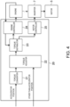
- Fig. 2 is a block diagram of the driving force control device.
- the controller 20 described above is installed in the automobile 1 in order to control the engine 4, the motor 5, the K0 clutch 6, the automatic transmission 8, etc. according to operation of the driver to control the traveling of the automobile 1.
- the controller 20 may be comprised of hardware, such as a processor, a memory, and an interface, and software, such as a database and a control program. Note that, although a sole controller 20 is illustrated in the driving force control device of Fig.
- the accelerator position sensor 51 outputs a signal corresponding to operation of an accelerator pedal 19 (see Fig. 1 ) which is operated by the driver.
- the intake pressure sensor 52 outputs a signal corresponding to a pressure at a part of the intake passage of the engine 4, upstream of the throttle valve 43.
- the water temperature sensor 53 outputs a signal corresponding to a temperature of coolant of the engine 4.
- the engine speed sensor 54 outputs a signal corresponding to an engine speed of the engine 4.
- the motor rotational speed sensor 55 outputs a signal corresponding to a rotational speed of the motor 5. Note that, in the automobile 1, when the K0 clutch 6 becomes in the connected state and each of the engine 4 and the motor 5 outputs a torque, the engine speed of the engine 4 coincides with the rotational speed of the motor 5.
- the vehicle speed sensor 56 outputs a signal corresponding to a traveling speed of the automobile 1 (vehicle speed).
- the SOC sensor 57 outputs a signal corresponding to an SOC of the high-voltage battery 9.
- the controller 20 receives these signals outputted from the sensors via the CAN 12.
- the controller 20 outputs the control signal to the engine 4, the inverter 7, the K0 clutch 6, and the automatic transmission 8 through the CAN 12.
- the controller 20 controls the engine 4, the motor 5, the K0 clutch 6, and the automatic transmission 8.
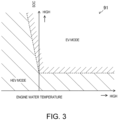
- Fig. 3 illustrates a map 91 according to the modes of the automobile 1.
- the automobile 1 may have an EV mode and an HEV mode.
- the EV mode is an "Electric Vehicle” mode, and is a mode in which only the motor 5 outputs a torque for the traveling of the automobile 1.
- the HEV mode is a "Hybrid Electric Vehicle” mode, and is a mode in which both the engine 4 and the motor 5 output a torque for the traveling of the automobile 1.
- the ignition timing is retarded from the MBT. Therefore, an exhaust loss increases.
- the engine 4 can achieve an early activation of the catalyst device by using the exhaust loss.
- the motor 5 assists the engine 4 which activates the catalyst device.
- Fig. 4 illustrates functional blocks of the controller 20.
- the controller 20 may include a torque converter 21, a torque adjuster 22, a torque distributor 23, an engine controller 24, and/or a motor controller 25, as functional blocks.
- the torque adjuster 22 receives the target torque set by the torque converter 21 based on the accelerator position, and sets a final target torque in response to a torque demand signal other than the accelerator position.
- the torque demand signal other than the accelerator position includes a torque demand signal for stabilizing the behavior of the automobile 1, for example.
- the torque distributor 23 distributes the target torque to a target engine torque and a target motor torque in response to the final target torque which is the target torque of the automobile 1 set by the torque adjuster 22. Note that, when the automobile 1 is in the EV mode, the target engine torque is zero, and the target motor torque coincides with the target torque of the automobile 1.
- the torque distributor 23 will be described later in detail.
- the engine controller 24 outputs a control signal corresponding to the target engine torque set by the torque distributor 23 to the engine 4 (in more detail, the spark plug 41, the injector 42, the throttle valve 43, and the intake S-VT 44).
- the engine 4 operates so that the target engine torque is realized.
- the motor controller 25 outputs a control signal corresponding to the target motor torque set by the torque distributor 23 to the inverter 7.
- the motor 5 is controlled through the inverter 7.
- the motor 5 operates so that the target motor torque is realized. By the engine 4 outputting the torque and the motor 5 outputting the torque, the target torque of the automobile 1 is achieved.
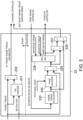
- Fig. 5 illustrates functional blocks of the torque distributor 23.
- the torque distributor 23 may include an SOC manager 231, a first adder subtracter 232, an engine torque calculator 233, a phase adjuster 234, a second adder subtracter 235, a limiter 236, a third adder subtracter 237, and an adder 238, as functional blocks.
- the SOC manager 231 receives the final target torque of the automobile 1 set by the torque adjuster 22.
- the SOC manager 231 also receives information on the high-voltage battery 9.
- the information on the high-voltage battery 9 includes at least the SOC of the high-voltage battery 9 based on a measurement signal from the SOC sensor 57, and a temperature of the high-voltage battery 9.
- the SOC manager 231 temporarily sets a target torque of the motor 5 based on the target torque of the automobile 1 and the battery information. For example, when the SOC is high, the SOC manager 231 increases the target motor torque to increase an amount of the assistance to the engine 4 by the motor 5. For example, when the SOC is low, the SOC manager 231 decreases the target motor torque to give priority to the charging of the high-voltage battery 9.
- the target motor torque set here is equivalent to a steady target motor torque.
- the first adder subtracter 232 subtracts the target motor torque set by the SOC manager 231 from the target torque of the automobile 1.
- the output of the first adder subtracter 232 is a first target engine torque.
- the first target engine torque is equivalent to a steady target engine torque.
- the first target engine torque can also be said as a torque achieved by adjusting the amount of air into the cylinder.
- the torque distributor 23 outputs the first target engine torque to the engine controller 24.
- the target torque of the automobile 1 changes.
- the target torque of the automobile 1 changes, the target engine torque and the target motor torque change.
- a target throttle opening and a target open-and-close timing of the intake valve are changed to change the amount of intake air into the cylinder.
- the change in the opening of the throttle valve 43 and/or the change in the open-and-close timing of the intake valve by the intake S-VT 44 take time, and it also takes time to actually change the amount of intake air into the cylinder after the opening of the throttle valve 43 and the open-and-close timing of the intake valve are changed. Further, it also takes time to actually change the torque of the engine 4 after the amount of intake air into the cylinder is actually changed.
- a time lag arises between the time the driver operates the accelerator pedal 19 and the time the torque of the engine 4 is changed to the target engine torque.
- the torque distributor 23 sets the target motor torque so that the slow torque response of the engine 4 is supplemented.
- the torque distributor 23 estimates an amount of intake air into the cylinder in the future from the present time, and estimates a torque of the engine 4 in the future based on the estimated amount of intake air.
- the torque distributor 23 sets the target motor torque based on the estimated torque of the engine 4 so that the target torque of the automobile 1 will be achieved in the future.
- the SOC manager 231 and the first adder subtracter 232 of the torque distributor 23 are related to a setup of the steady target engine torque (i.e., the first target engine torque).
- the engine torque calculator 233, the phase adjuster 234, the second adder subtracter 235, the limiter 236, the third adder subtracter 237, and the adder 238 are related to a setup of a transitional target engine torque (a second target engine torque which will be described later), and a setup of the target motor torque.
- the engine torque calculator 233 reads the estimated value of the amount of intake air into the cylinder in the future from the present time.
- the estimation of the amount of intake air is performed by the engine controller 24, as will be described later.
- the engine controller 24 outputs the estimated value of the amount of intake air after a reference time which is defined beforehand with respect to the present time.
- the engine torque calculator 233 estimates the torque of the engine 4 in the future from the present time based on the estimated value of the amount of intake air.
- the engine torque calculator 233 estimates the torque of the engine 4 when the spark plug 41 ignites at an optimal ignition timing which is defined based on the operating state of the engine 4, based on the estimated value of the amount of intake air.
- the optimal ignition timing is the MBT described above. That is, the engine torque calculator 233 estimates the torque of the engine 4 when the spark plug 41 ignites at the MBT, based on the estimated value of the amount of intake air. Further, when the engine operates in the AWS mode, the optimal ignition timing is a timing which is retarded from the MBT. That is, the engine torque calculator 233 may estimate the torque of the engine 4 when the spark plug 41 ignites at the timing retarded from the MBT, based on the estimated value of the amount of intake air.
- the phase adjuster 234 synchronizes the torque change of the engine 4 with the torque change of the motor 5, for example, in consideration of a communication delay of the controller 20, a response delay of the motor 5, and a response delay of the engine 4. Generally, the torque response of the engine 4 is slower than the torque response of the motor 5.
- the phase adjuster 234 adjusts a phase of the torque estimated value of the engine 4 in consideration of a torque response difference between the motor 5 and the engine 4.
- the engine controller 24 estimates the amount of intake air after the reference time (i.e., a fixed time) with respect to the present time.
- the period of time required for reflecting the amount of intake air after the reference time to the torque of the engine 4 varies according to the engine speed of the engine 4.
- Fig. 7 illustrates a relationship between the engine speed and the delay time.
- the delay time corresponds to a delay from the change in the amount of intake air to the torque change of the engine 4.
- the delay time is long. In other words, as the engine speed becomes lower, the delay time becomes longer.
- the delay time is short.
- the relationship between the engine speed and the delay time is set to be linear so that the delay time becomes shorter as the engine speed increases.
- the controller 20 stores the relational expression illustrated in Fig. 7 . Note that the relationship between the engine speed and the delay time is not limited to the illustrated example.
- the relationship between the engine speed and the delay time may be a curve, without being limited to the straight line. Further, the relationship between the engine speed and the delay time may be stepwise.
- the phase adjuster 234 sets the delay time based on the engine speed.
- the estimated amount of intake air is reflected to the torque of the engine 4 after the delay time.
- the controller 20 estimates the torque of the engine 4 after the setup time from the present time.
- the setup time related to the torque estimation can be set as an arbitrary period of time, as long as it is a time after the reference time related to the estimation of the amount of intake air.
- the delay time becomes zero. If the engine speed of the engine 4 becomes higher than the reference engine speed r0, since the response of the torque change of the engine 4 to the accelerator operation is sufficiently high, it is not necessary to provide the delay time. Thus, when the engine speed of the engine 4 is higher than the reference engine speed, the controller 20 can estimate the torque of the engine 4 with sufficient accuracy, even if the delay time is set to zero.
- the torque response of the engine 4 becomes equivalent to the torque response of the motor 5, or the torque response of the motor 5 becomes slower than the torque response of the engine 4.
- the engine speed of the engine 4 is high, it is considered to make the torque response of the motor 5 faster in order to synchronize the torque response of the engine 4 with the torque response of the motor 5.
- the torque response of the engine 4 substantially synchronizes with the torque response of the motor 5, even if the torque response of the motor 5 is not made faster.
- the second adder subtracter 235 subtracts it from the target torque of the automobile 1.
- the estimated torque of the engine 4 after the setup time includes the delay of the torque response of the engine 4. If the output of the second adder subtracter 235 is the target motor torque after the setup time from the present time, the target torque of the automobile 1 can be achieved by adding the motor torque to the estimated torque of the engine 4. That is, the target motor torque supplements the delay of the torque response of the engine 4.
- the limiter 236 outputs a final target motor torque based on the target motor torque outputted from the second adder subtracter 235, a maximum torque of the motor 5, and a minimum torque.
- the maximum motor torque and the minimum motor torque are set according to the performance of the motor 5, the temperature of the motor 5, and/or the SOC of the high-voltage battery 9. For example, if the SOC is high, since the regenerative operation of the motor 5 cannot be carried out, the minimum motor torque is set to small. If the SOC is low, since the high-voltage battery 9 has to be charged, the maximum motor torque is set to small.
- the limiter 236 sets the target motor torque to the maximum motor torque.
- the limiter 236 sets the target motor torque to the minimum motor torque.
- the limiter 236 sets the target motor torque outputted from the second adder subtracter 235 as the final target motor torque.
- the motor controller 25 controls the motor 5 through the inverter 7 based on the target motor torque outputted from the limiter 236.
- the motor 5 supplements the engine 4 so that the target torque of the automobile 1 after the setup time from the present time is achieved, and outputs the torque.
- the torque change of the engine 4 is synchronized with the torque change of the motor 5, and the deviation of the actual torque from the target torque is suppressed.
- the target motor torque outputted from the limiter 236 is larger than the target motor torque outputted from the second adder subtracter 235. If the motor 5 keeps outputting the target motor torque (i.e., the minimum motor torque) as the engine 4 keeps outputting the target engine torque, the torque of the automobile 1 after the setup time from the present time will exceed the target torque.
- the target motor torque i.e., the minimum motor torque
- the third adder subtracter 237 calculates a difference between the target motor torque outputted from the second adder subtracter 235 and the target motor torque outputted from the limiter 236. When the difference is zero, the limiter 236 does not limit the target motor torque by the maximum motor torque or the minimum motor torque. When the difference is not zero, the limiter 236 limits the target motor torque by the maximum motor torque or the minimum motor torque.
- the adder 238 sets the second target engine torque by adding the output of the third adder subtracter 237 to the output of the engine torque calculator 233.
- the adder 238 outputs the second target engine torque to the engine controller 24.
- the output of the third adder subtracter 237 is the above-described difference, and the output of the engine torque calculator 233 is the torque of the engine 4 estimated from the estimated value of the amount of intake air.
- the second target engine torque is related to adjustment of the ignition timing. Concretely, when the target motor torque is limited by the minimum motor torque, the ignition timing is retarded from the optimal ignition timing (i.e., the MBT, or the ignition timing during the AWS) so that the torque of the engine 4 is reduced.
- the second target engine torque is the torque achieved by adjusting the ignition timing, and is equivalent to the transitional target engine torque.
- the engine controller 24 controls the amount of intake air of the engine 4 and the ignition timing based on the first target engine torque and the second target engine torque.
- the torque of the engine 4 is reduced.
- the amount of increase in the motor torque is canceled out by the torque reduction of the engine 4.
- the target motor torque when the target motor torque is limited by the maximum motor torque, the torque of the motor 5 is relatively lowered. Unless the torque of the engine 4 is raised, the target torque of the automobile 1 cannot be realized. However, under operation by using the optimal ignition timing, it is difficult to further raise the torque of the engine 4. When the target motor torque is limited by the maximum motor torque in the limiter 236, the adjustment of the ignition timing is not performed.
- Fig. 6 illustrates functional blocks of the engine controller 24 related to the estimation of the amount of intake air.
- the engine controller 24 includes a throttle opening estimator 241, a throttle passing air amount estimator 242, a fourth adder subtracter 243, an intake manifold air amount estimator 244, a pressure converter 245, an S-VT change estimator 246, a charging efficiency estimator 247, and a multiplier 248.
- the engine controller 24 estimates the amount of intake air after the reference time from the present time.
- the reference time may be a fixed period of time and may be set beforehand.
- the reference time can be set arbitrarily, for example, between ten to several tens milliseconds.
- the throttle opening estimator 241 estimates the change in the opening of the throttle valve 43 with the progress of time, based on the first target engine torque set by the torque distributor 23.
- the throttle opening estimator 241 estimates an opening of the throttle valve 43 after the reference time from the present time based on the target opening of the throttle valve 43 and characteristic information on the throttle valve 43.
- a relationship between the target engine torque and the target opening of the throttle valve 43 may be stored in the controller 20.
- the characteristic information on the throttle valve 43 is also stored in the controller 20.
- the characteristics of the throttle valve 43 may be identified, for example, by performing an actual machine test. As illustrated in Fig. 6 , the opening of the throttle valve 43 changes with a delay from the operation of the accelerator pedal 19.
- the throttle passing air amount estimator 242 estimates an amount of air which passes through the throttle valve 43 after the reference time from the present time.
- the throttle passing air amount estimator 242 estimates the amount of air which passes through the throttle valve 43 e.g., by using the Bernoulli's equation based on the opening of the throttle valve 43 estimated by the throttle opening estimator 241, a pressure of the intake manifold downstream of the throttle valve 43, and the intake pressure upstream of the throttle valve 43.
- the pressure of the intake manifold a value obtained by the pressure converter 245 converting an amount of air inside the intake manifold after the reference time from the present time into the pressure is used, which will be described later.
- the intake pressure upstream of the throttle valve 43 can be acquired, for example, from the measurement signal of the intake pressure sensor 52.
- the fourth adder subtracter 243 subtracts the amount of intake air into the cylinder (described later) from the amount of air passing through the throttle valve 43 after the reference time from the present time, which is estimated by the throttle passing air amount estimator 242.
- the intake manifold air amount estimator 244 estimates the amount of air inside the intake manifold after the reference time from the present time based on the output from the fourth adder subtracter 243.
- the pressure converter 245 converts the amount of air inside the intake manifold after the reference time from the present time, which is estimated by the intake manifold air amount estimator 244, into the pressure inside the intake manifold, and outputs it to the throttle passing air amount estimator 242.
- the S-VT change estimator 246 estimates the change in the open-and-close timing of the intake valve by the intake S-VT 44 with the progress of time based on the first target engine torque, similarly to the throttle opening estimator 241.
- the S-VT change estimator 246 estimates the open-and-close timing of the intake valve after the reference time from the present time, based on the target open-and-close timing of the intake valve and the characteristic information on the intake S-VT 44.
- the relationship between the target engine torque and the target open-and-close timing of the intake valve is stored in the controller 20.
- the characteristic information on the intake S-VT 44 is also stored in the controller 20.
- the characteristics of the intake S-VT 44 may be identified, for example, by performing an actual machine test. As illustrated in Fig. 6 , the open-and-close timing of the intake valve changes with a delay from the operation of the accelerator pedal 19.
- the charging efficiency estimator 247 estimates a charging efficiency after the reference time from the present time based on the open-and-close timing of the intake valve after the reference time from the present time, which is estimated by the S-VT change estimator 246.
- the controller 20 may store beforehand a map indicative of a relationship between the open-and-close timing of the intake valve, the operating state of the engine 4, and the charging efficiency.
- the charging efficiency estimator 247 estimates the charging efficiency after the reference time from the present time based on the map stored in the controller 20.
- the multiplier 248 estimates the amount of intake air into the cylinder after the reference time from the present time by multiplying the amount of air inside the intake manifold after the reference time from the present time, which is estimated by the intake manifold air amount estimator 244, by the charging efficiency after the reference time from the present time, which is estimated by the charging efficiency estimator 247.
- the estimated amount of intake air is used for the control of the engine 4, and is also outputted to the engine torque calculator 233 of the torque distributor 23 as described above.
- Fig. 8 illustrates one example of the control by the driving force control device for the vehicle.
- the time chart of Fig. 8 includes operation of the accelerator pedal 19, a change in the target torque of the automobile 1, a change in the target amount of intake air, a change in the estimated amount of intake air, a change in the estimated engine torque value, a change in the target motor torque, and a change in the ignition timing.
- This example of control corresponds to a case where the automobile 1 is accelerated by the driver stepping on the accelerator pedal 19, while the automobile 1 travels in the HEV mode.
- the driver steps on the accelerator pedal 19 at a time t1.
- the torque converter 21 and the torque adjuster 22 set the target torque of the automobile 1 so that it corresponds to the operation of the accelerator pedal 19.
- This target torque is a torque which is realized by the torque of the engine 4 and the torque of the motor 5.
- the target torque increases in a stepwise manner at the time t1.
- the torque distributor 23 sets the target engine torque so that it corresponds to the change in the target torque.
- the target engine torque increases in a stepwise manner similarly to the target torque.
- the target amount of intake air of the engine 4 is set so that it corresponds to the target engine torque.
- the target amount of intake air also increases in a stepwise manner at the time t1.
- the opening of the throttle valve 43 changes so that the target amount of intake air is realized. Since the change in the opening of the throttle valve 43 is delayed from the operation of the accelerator pedal 19 as described above, the throttle opening changes gradually with the progress of time as illustrated by a one-dot chain line in Fig. 8 .
- the engine controller 24 estimates a change in the throttle opening, and based on the estimation, it estimates the amount of intake air after the reference time from the present time.
- the estimated amount of intake air increases gradually with the progress of time from a time t2 which is after the time t1 so that it corresponds to the change in the throttle opening.
- the engine torque calculator 233 of the torque distributor 23 calculates an engine torque based on the estimated amount of intake air.
- the engine torque calculator 233 estimates the torque of the engine 4, for example, when the spark plug 41 ignites at the MBT.
- the phase adjuster 234 adjusts the phase of the torque of the engine 4.
- a delay time is set.
- the estimated engine torque increases gradually with the progress of time from a time t3 which is after the time 11.
- the ignition timing changes after the time t3. Note that the ignition timing is assumed to be the MBT also after the time t3.
- the torque distributor 23 sets a target motor torque based on the target torque and the estimated engine torque value.
- the target motor torque is set so that the delay of the torque change of the engine 4 is supplemented. From the time t1 to the time t3, the torque of the engine 4 does not change (i.e., the torque does not rise). Thus, the target torque is realized by the target motor torque rising in a stepwise manner at the time t1. Therefore, the response delay of the torque change of the automobile 1 with respect to the operation of the accelerator pedal 19 is suppressed.
- the target motor torque falls gradually.
- the torque change of the engine 4 synchronizes with the torque change of the motor 5. Therefore, the deviation of the actual torque of the automobile 1 from the target torque is suppressed.
- the target torque is achieved also after the time t3.
- the motor 5 supplements the delay of the torque reduction of the engine 4 in this driving force control device.
- the response delay of the torque change of the automobile 1 with respect to the operation of the accelerator pedal 19 is suppressed, and the deviation of the actual torque of the automobile 1 from the target torque is suppressed.
- the engine 4 can reduce the torque by reducing the amount of intake air, while maintaining the MBT without retarding the ignition timing. Therefore, the fuel efficiency of the automobile 1 improves.
- Fig. 9 illustrates a modification of the torque distributor 230.
- Fig. 9 illustrates some of functional blocks of the torque distributor 230.
- the torque distributor 230 includes an SOC manager 231, a first adder subtracter 232 (omitted in Fig. 9 ), an engine torque calculator 233, a phase adjuster 234, a second adder subtracter 235, a limiter 236, a third adder subtracter 237, an adder 238, and a second adder 239.
- the engine torque calculator 233 estimates the torque of the engine 4 in the future based on the amount of intake air estimated by the engine controller 24, as described above.
- the phase adjuster 234 adjusts the phase of the torque of the engine 4 according to the engine speed of the engine 4.
- the second adder 239 adds the output of the second adder subtracter 235 to the output of the SOC manager 231.
- the output of the second adder subtracter 235 is the difference between the estimated engine torque and the first target engine torque.
- the output of the SOC manager 231 is the target motor torque set based on the target torque of the automobile 1 and the battery information, as described above. In other words, the second adder 239 corrects the target motor torque set by the SOC manager 231 so that the delay of the torque response of the engine 4 is supplemented.
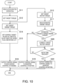
- Step S21 the controller 20 determines whether it reaches the setup time related to the torque estimation of the engine 4. If the determination of Step S21 is No, the process repeats Step S21, and if the determination of Step S21 is Yes, the process transits to Step S22.
- the motor controller 25 outputs the control signal according to the corrected target motor torque to the inverter 7. Therefore, the torque change of the motor 5 synchronizes with the torque change of the engine 4. The response delay of the torque change with respect to the operation of the accelerator pedal 19 is suppressed, and the deviation of the actual torque of the automobile 1 from the target torque is suppressed. The target torque of the automobile 1 is achieved.
- the motor controller 25 outputs at Step S19 the control signal according to the target motor torque set at Step S13 to the inverter 7.
- the motor 5 is controlled through the inverter 7 so that the target motor torque (as a result, the target torque of the automobile 1) is achieved.
- the driving force control device for the vehicle includes the motor 5 which generates the torque for the vehicle to travel by being supplied with electric power, the engine 4 which combusts fuel inside the cylinder to generate the torque for the vehicle to travel, and the controller 20 which receives the accelerator operation signal and outputs the control signal corresponding to the accelerator operation to the motor 5 and the engine 4.
- the controller 20 sets the target torque of the vehicle corresponding to the accelerator operation (the torque converter 21, the torque adjuster 22), and distributes the target engine torque according to a distribution rule defined beforehand (the torque distributors 23, 230), based on the target torque of the vehicle, and outputs the control signal corresponding to the target engine torque to the engine 4 (the engine controller 24).
- the controller 20 estimates the amount of intake air into the cylinder in the future from the present time based on the target engine torque (the engine controller 24, Fig. 6 ), and estimates the torque of the engine 4 after the setup time from the present time based on the estimated amount of intake air (the engine torque calculator 233, phase adjuster 234).
- the controller 20 sets the target motor torque after the setup time based on the estimated torque of the engine 4 after the setup time so that the target torque of the vehicle is achieved (the second adder subtracter 235, the limiter 236, the second adder 239), and outputs the control signal corresponding to the target motor torque to the motor 5 (the motor controller 25) to synchronize the torque response of the engine with the torque response of the motor 5.
- the target motor torque is set based on the estimated engine torque in the future, the torque response of the engine synchronizes with the torque response of the motor in this driving force control device.
- the deviation of the actual torque from the target torque can be eliminated or substantially eliminated.
- the controller 20 delays the torque change of the engine 4 with respect to the estimated change in the amount of intake air more, as the engine speed of the engine 4 decreases (the phase adjuster 234, Fig. 7 ).
- the controller 20 can estimate the change in the torque of the engine 4 in the future from the present time with sufficient accuracy.
- the controller 20 shortens the delay time related to the torque change more, as the engine speed of the engine 4 increases, and, when the engine speed of the engine 4 is higher than the reference engine speed r0, it sets the delay time to zero (the phase adjuster 234, Fig. 7 ).
- the estimation accuracy of the torque of the engine 4 in the future from the present time increases. Further, since the engine speed of the engine 4 is high, even if the delay time is set to zero, the controller 20 can estimate the torque of the engine 4 with sufficient accuracy.
- the controller 20 sets the target motor torque to supplement the difference between the estimated torque of the engine 4 and the target engine torque (the second adder subtracter 235, the second adder 239, Fig. 9 ).
- the motor 5 can supplement the response delay of the engine 4.
- the controller 20 estimates the torque of the engine 4 after the setup time from the present time based on the estimated amount of intake air and the optimal ignition timing which is defined based on the operating state of the engine 4 (the engine torque calculator 233, the phase adjuster 234).
- the controller 20 sets the target motor torque higher than the minimum torque which can be generated by the motor 5 (the limiter 236).
- the controller 20 retards the ignition timing of the engine 4 from the optimal ignition timing so that the torque of the engine 4 is reduced (the third adder subtracter 237, the adder 238).
- the controller 20 estimates the change in the opening of the throttle valve 43 of the engine 4 after the accelerator operation, based on the target engine torque (the throttle opening estimator 241), estimates the amount of air which passes through the throttle valve 43 based on the estimated opening of the throttle valve 43 and the pressure of the intake manifold of the engine 4 (the throttle passing air amount estimator 242), estimates the amount of air inside the intake manifold based on the estimated amount of air which passes through the throttle valve 43 (the intake manifold air amount estimator 244), and estimates the amount of intake air into the cylinder based on the estimated amount of air inside the intake manifold (the multiplier 248).
- the controller 20 can estimate the amount of intake air into the cylinder in the future from the present time.
- the controller 20 estimates the change in the open-and-close timing of the intake valve of the engine 4 after the accelerator operation based on the target engine torque (the S-VT change estimator 246), estimates the charging efficiency based on the estimated open-and-close timing of the intake valve (the charging efficiency estimator 247), and estimates the amount of intake air into the cylinder based on the estimated charging efficiency and the estimated amount of air inside the intake manifold (the multiplier 248).
- the controller 20 can estimate the amount of intake air into the cylinder in the future from the present time with sufficient accuracy.
Landscapes
- Engineering & Computer Science (AREA)
- Chemical & Material Sciences (AREA)
- Combustion & Propulsion (AREA)
- Mechanical Engineering (AREA)
- Transportation (AREA)
- Automation & Control Theory (AREA)
- Signal Processing (AREA)
- Theoretical Computer Science (AREA)
- General Engineering & Computer Science (AREA)
- Human Computer Interaction (AREA)
- Physics & Mathematics (AREA)
- Mathematical Physics (AREA)
- Electric Propulsion And Braking For Vehicles (AREA)
- Hybrid Electric Vehicles (AREA)
- Control Of Vehicle Engines Or Engines For Specific Uses (AREA)
- Combined Controls Of Internal Combustion Engines (AREA)
- Electrical Control Of Ignition Timing (AREA)
- Electrical Control Of Air Or Fuel Supplied To Internal-Combustion Engine (AREA)
Abstract
Description
- The technology disclosed herein relates to a driving force control device for a vehicle, and a vehicle.
-
JP2006-067737A - The hybrid vehicle in which the engine and the motor are mounted distributes a target torque of the vehicle to the engine and the motor so that the energy efficiency becomes the optimal. The torque distribution to the engine and the motor changes in turn, for example, according to an SOC (State of Charge), a battery state such as a temperature, and/or an engine state including an engine water temperature.
- Generally, the torque response of the engine is slower than the torque response of the motor. Therefore, during a transition in which the target torque changes, a torque change of the engine may be delayed from a torque change of the motor. The delay of the torque change of the engine causes a torque change of the vehicle. Further, the delay of the torque change of the engine may cause a deviation of the sum total torque which is actually generated by the engine and the motor from the target torque.
- Conventional hybrid vehicles delay a timing of the torque increase of the motor so that it coincides with a timing of the torque increase of the engine. In the conventional hybrid vehicles, since the engine torque increase synchronizes with the motor torque increase, the torque change does not easily occur.
- However, in the conventional hybrid vehicles, in order to delay the timing of the motor torque increase, the torque increase of the automobile is delayed from the driver's accelerator operation. The conventional hybrid vehicles are not good in the drivability. Further, unfortunately, since the conventional hybrid vehicles only synchronize the engine torque increase with the motor torque increase, the deviation of the actual torque from the target torque cannot be improved.
- The technology disclosed herein improves a deviation of an actual torque from a target torque, while suppressing a response delay of a torque change from a driver's accelerator operation.
- In a hybrid vehicle in which an engine and a motor are mounted, it is possible to achieve both suppression of a response delay and improvement in a deviation of a torque by making the motor supplement the response delay of the engine. That is, when changing a target engine torque according to a driver's accelerator operation, it is possible that a controller calculates a difference between an actual engine torque and the target engine torque, and corrects a target motor torque so that the difference in the engine torque is supplemented by the motor torque. A high-response motor can supplement the difference in the engine torque caused by the response delay of the engine. The supplement by the motor can suppress the response delay of the torque with respect to the accelerator operation, and can also improve the deviation of the actual torque from the target torque.
- However, it takes time for detecting the engine torque, calculating the torque difference, and/or setting an amount of correction of the motor torque. In the above-described control process, the actual engine torque changes every moment even during the setting of the amount of correction of the motor after detecting the engine torque. The correction of the motor torque follows after the change in the actual engine torque. The deviation of the actual torque from the target torque is not eliminated.
- The present inventors conceived a technical idea of predicting the change in the engine torque to estimate the engine torque in the future from the present time and setting a target motor torque after a setup time from the present time based on the estimated engine torque. The present inventors proceeded with establishment of a control for realizing the technical idea, and completed the technology disclosed herein.
- The invention is defined in claim 1. Particularly, the technology disclosed herein relates to a driving force control device for a vehicle, or a vehicle. The driving force control device for a vehicle or the vehicle includes a motor which generates a torque for the vehicle to travel by being supplied with electric power, an engine which combusts fuel inside a cylinder to generate a torque for the vehicle to travel, and a controller which receives an accelerator operation signal and outputs a control signal corresponding to the accelerator operation to the motor and the engine. The controller sets a target torque of the vehicle corresponding to the accelerator operation, and distributes a target engine torque according to a distribution rule defined beforehand, based on the target torque of the vehicle, and outputs a control signal corresponding to the target engine torque to the engine. The controller estimates an amount of intake air into the cylinder based on the target engine torque. Particularly, the controller estimates an amount of intake air into the cylinder in the future from the present time based on the target engine torque. The controller estimates a torque of the engine based on the estimated amount of intake air. Particularly, the controller estimates a torque of the engine after a setup time from the present time based on the estimated amount of intake air. The controller sets a target motor torque based on the estimated torque of the engine so that the target torque of the vehicle is achieved. Particularly, the controller sets a target motor torque after the setup time based on the estimated torque of the engine after the setup time so that the target torque of the vehicle is achieved. The controller outputs a control signal corresponding to the target motor torque to the motor to synchronize a torque response of the engine with a torque response of the motor.
- In this configuration, the vehicle is provided with the motor and the engine. In other words, the vehicle may be is a hybrid vehicle. The controller distributes the target torque of the vehicle to the target engine torque and the target motor torque so that the target torque of the vehicle corresponding to the accelerator operation is achieved. The engine outputs the target engine torque, and the motor outputs the target motor torque. The engine and the motor realize the target torque of the vehicle.
- The controller distributes the target engine torque according to the distribution rule defined beforehand. The distribution rule is, for example, based on an SOC of a battery. The battery is mounted on the vehicle for supplying electric power to the motor. When the SOC is high, the controller may decrease the target engine torque and increase the target motor torque increases to give priority to electric discharge of the battery. When the SOC is low, the controller may increase the target engine torque and decrease the target motor torque to give priority to the charging of the battery. The controller outputs a control signal corresponding to the target engine torque to the engine. The engine operates to output the target engine torque.
- When the driver operates the accelerator, the controller changes the target torque of the vehicle according to the change in the accelerator operation. In response to the change in the target torque of the vehicle, the controller changes the target engine torque. When the target engine torque changes, the engine changes, for example, the throttle valve opening, resulting in a change in the amount of intake air into the cylinder. The change in the amount of intake air into the cylinder changes the engine torque. A time lag arises between the time the target torque is changed and the time the engine torque is actually changed through the change in the throttle valve opening and the change in the amount of intake air.
- The change in the throttle valve opening according to the change in the target engine torque can be estimated by identifying beforehand, for example, characteristics of the throttle valve (including, for example, mechanical characteristics). When the change in the throttle valve opening in the future from the present time can be estimated, the amount of intake air in the future can be estimated. When the amount of intake air can be estimated, the engine torque in the future can be estimated. The controller estimates the engine torque in the future based on the target engine torque. In more detail, the controller estimates the torque of the engine after the setup time from the present time.
- Further, when the engine torque after the setup time from the present time is estimated, the controller sets the target motor torque after the setup time so that the target torque of the vehicle is achieved. If the estimated engine torque is lower than the target engine torque, the target motor torque is set to large to supplement the insufficient engine torque. If the estimated engine torque is higher than the target engine torque, the target motor torque is set to small, in consideration of the excess of the engine torque. The set target motor torque supplements the delay of the torque response of the engine.
- The controller outputs the control signal corresponding to the target motor torque to the motor. Since the torque response of the motor is generally high, the motor can output the torque corresponding to the target motor torque after the setup time. The torque response of the engine synchronizes with the torque response of the motor. As a result, the torque variation of the vehicle is suppressed, and further, the target torque of the vehicle is achieved.
- Since the high-response motor supplements the response delay of the engine, the response delay of the torque change with respect to the accelerator operation is suppressed in the above-described driving force control device.
- Further, the engine torque in the future is estimated and the target motor torque is set based on the estimated engine torque in the future, instead of the actual engine torque. The set target motor torque does not follow after the change in the actual engine torque. In the above-described driving force control device, the deviation of the actual torque from the target torque can be eliminated or substantially eliminated by synchronizing the torque response of the engine with the torque response of the motor.
- As a result, the above-described driving force control device improves the drivability of the driver.
- When estimating the torque of the engine, the controller may delay a torque change of the engine with respect to a change in the estimated amount of intake air as an engine speed of the engine increases.
- When the engine speed is high, a combustion interval (i.e., a time interval) of the plurality of cylinders of the engine is short. When the engine speed is low, the combustion interval (i.e., the time interval) of the plurality of cylinders is long. A time after the amount of intake air into the cylinder changes until the torque of the engine actually changes varies according to the engine speed. When the engine speed is high, the time after the amount of intake air into the cylinder changes until the torque of the engine changes is short. When the engine speed is low, the time after the amount of intake air into the cylinder changes until the torque of the engine changes is long.
- When the engine speed is low, the controller delays the torque change of the engine with respect to the change in the estimated amount of intake air as the engine speed decreases. The controller can estimate the torque change of the engine in the future from the present time with sufficient accuracy. By setting the target motor torque based on the torque of the engine after the setup time, which is estimated with high accuracy, the torque response of the engine synchronizes with the torque response of the motor, and the torque of the vehicle coincides with the target torque with sufficient accuracy. The driving force control device can eliminate or substantially eliminate the deviation of the actual torque from the target torque, while suppressing the response delay of the torque change with respect to the accelerator operation.
- The controller may shorten a delay time according to the torque change as the engine speed increases, and set the delay time to zero when the engine speed is higher than a reference engine speed.
- The delay time after the change of the amount of intake air into the cylinder until the change in the torque of the engine becomes shorter, as the engine speed increases. By shortening the delay time related to the torque change as the engine speed increases, the accuracy of the estimation of the engine torque in the future from the present time is improved.
- When the engine speed is sufficiently high, the delay time related to the torque change becomes very short, which reduces the necessity of intentionally setting the delay time. Thus, when the engine speed is higher than the reference engine speed, the controller can estimate the torque of the engine with sufficient accuracy, even if the delay time is set to zero.
- Note that, the response of the torque change of the engine becomes higher as the engine speed increases, and as a result, the response of the torque change of the engine becomes equivalent to the response of the torque change of the motor, or higher than the response of the torque change of the motor. When the engine speed is high, it is considered to make the torque response of the motor faster in order to synchronize the torque response of the engine with the torque response of the motor. However, since the time required for the engine and the motor making one revolution becomes shorter, the torque response of the engine substantially synchronizes with the torque response of the motor, even if the torque response of the motor is not made faster.
- The controller may set the target motor torque so as to supplement a difference between the estimated torque of the engine and the target engine torque.
- The motor can supplement the response delay of the engine.
- The controller may estimate the torque of the engine after the setup time from the present time based on the estimated amount of intake air and an optimal ignition timing defined based on an operating state of the engine.
- Here, the optimal ignition timing may be, for example, MBT (Minimum spark advance for the Best Torque). When the controller sets the target engine torque based on the MBT, the engine operates at the best efficiency. The motor can assist the engine which operates at the best efficiency.
- Further, for example, when a catalyst device of the engine is inactive, and the engine operates in an AWS (Accelerated Warm-up System) mode, the optimal ignition timing is retarded from the MBT. The optimal ignition timing is not limited to the MBT. In this case, the engine can achieve an early activation of the catalyst device. The motor can assist the engine, while the early activation of the catalyst device is achieved.
- The controller may set the target motor torque higher than a minimum torque that is generatable by the motor. When the target motor torque is limited by the minimum torque, the controller may retard the ignition timing of the engine from the optimal ignition timing so that the torque of the engine is reduced.
- The minimum torque generatable by the motor is generally defined by the temperature condition. Further, if the SOC of the battery is high, since the regenerative operation of the motor cannot be carried out, the minimum motor torque is decreased. The minimum generatable torque is also defined by the motor performance. The controller should set the target motor torque to be higher than the minimum torque generatable by the motor. When the target motor torque is limited by the minimum torque, the set target motor torque is relatively high. The total torque of the motor torque and the engine torque (i.e., the actual torque of the vehicle) may exceed the target torque.
- When the target motor torque is limited by the minimum torque, the controller retards the ignition timing of the engine from the optimal ignition timing. Since the retard of the ignition timing decreases the engine torque, it can be avoided that the torque of the vehicle exceeds the target torque.
- The controller may estimate a change in an opening of a throttle valve of the engine after an accelerator operation, based on the target engine torque, estimate an amount of air passing through the throttle valve based on a change in the estimated opening of the throttle valve and a pressure of an intake manifold of the engine, estimate an amount of air inside the intake manifold based on the estimated amount of air passing through the throttle valve, and estimate an amount of intake air into the cylinder based on the estimated amount of air inside the intake manifold.
- The change of the throttle valve opening after the accelerator operation can be estimated by identifying beforehand, for example, the mechanical characteristics of the throttle valve. When the throttle opening in the future from the present time can be estimated, the amount of air which passes through the throttle valve in the future from the present time can be estimated by using the Bernoulli's equation based on the pressure of the intake manifold downstream of the throttle valve and the intake pressure upstream of the throttle valve. Note that, as for the pressure of the intake manifold, a value obtained by converting the amount of air inside the intake manifold into the pressure is used, as will be described later. Further, for example, a pressure sensor may measure the intake pressure upstream of the throttle valve.
- When the amount of air which passes through the throttle valve can be estimated, the amount of air inside the intake manifold can be estimated. When the amount of air inside the intake manifold can be estimated, the amount of intake air into the cylinder can be estimated. The controller can estimate the amount of intake air into the cylinder in the future from the present time.
- The controller may estimate a change in an open-and-close timing (or an open-and/or-close timing) of an intake valve of the engine after the accelerator operation based on the target engine torque, estimate a charging efficiency based on the estimated open-and-close timing of the intake valve, and estimate an amount of intake air into the cylinder based on the estimated charging efficiency and the estimated amount of air inside the intake manifold.
- The change of the open-and-close timing of the intake valve after the accelerator operation can be estimated by identifying beforehand characteristics (including, for example, mechanical characteristics) of a valve mechanism which changes the open-and-close timing of the intake valve. Further, as for the engine, by identifying beforehand a relationship between the open-and-close timing of the intake valve, the operating state of the engine, and the charging efficiency, the controller can estimate the charging efficiency based on the estimated open-and-close timing.
- When the charging efficiency can be estimated, the amount of intake air into the cylinder can be estimated with higher accuracy, based on the amount of air inside the intake manifold and the charging efficiency as described above. The controller can estimate the amount of intake air into the cylinder in the future from the present time with sufficient accuracy.
-
-
Fig. 1 illustrates a hybrid vehicle. -
Fig. 2 is a block diagram of a driving force control device. -
Fig. 3 illustrates a map according to a mode of the hybrid vehicle. -
Fig. 4 illustrates functional blocks of a controller. -
Fig. 5 illustrates functional blocks of a torque distributor. -
Fig. 6 illustrates functional blocks of an engine controller. -
Fig. 7 illustrates a relationship between an engine speed and a delay time. -
Fig. 8 illustrates a time chart of a driving force control. -
Fig. 9 illustrates a modification of the torque distributor. -
Fig. 10 is a flowchart according to a control of the driving force control device. - Hereinafter, one embodiment of a driving force control device for a vehicle is described with reference to the accompanying drawings. The driving force control device described herein is an illustrative example. All of the features as shown in the drawings may not necessarily be essential.
- An automobile 1 (one example of the vehicle) to which the disclosed technology is applied is illustrated in
Fig. 1 . This automobile 1 may be a hybrid vehicle which is travelable using electric power (or propellable by electric power). The automobile 1 has wheels, particularly a total of four wheels, comprised offront wheels 2F andrear wheels 2R. - An
engine 4 and amotor 5 are mounted on the automobile 1 as driving sources. These may collaborate with each other to drive therear wheels 2R. Thus, the automobile 1 travels. The automobile 1 may be a rear-wheel-drive vehicle. Themotor 5 may be used not only as the driving source but also as a generator during regeneration. - This automobile 1 carries a battery, particularly a high-
voltage battery 9. By the electric power supply from the high-voltage battery 9, themotor 5 generates a torque for the traveling of the automobile 1. The high-voltage battery 9 may be connected with anexternal power source 31 via a chargingport 3. The high-voltage battery 9 may be charged by theexternal power source 31. The automobile 1 may be a "plug-in hybrid vehicle." Note that the automobile 1 may be a hybrid vehicle from which the chargingport 3 is omitted. - In this automobile 1, the
engine 4 may be disposed at a front part of the vehicle body, and the driving wheels may be disposed in a rear part of the vehicle body. That is, this automobile 1 may be a "FR vehicle." - The automobile 1 may be provided with, in addition to the
engine 4 and themotor 5, aK0 clutch 6, aninverter 7, and anautomatic transmission 8, as devices in a drive system. The automobile 1 is also provided with acontroller 20, as a device in a control system. - The
engine 4 is an internal combustion engine which combusts, for example, fossil fuel. Further, theengine 4 may be a "four-cycle engine" which generates a rotational motive force by repeating a cycle of intake, compression, expansion, and exhaust. - The
engine 4 may be a spark-ignition engine. Note that theengine 4 may be a compression-ignition engine. Theengine 4 may have a plurality of cylinders. Note that the number of cylinders of theengine 4 is not limited to a specific number. - In this automobile 1, the
engine 4 is disposed substantially in a center part in the vehicle width direction in a state where acrankshaft 4a which outputs the rotational motive force is oriented in the front-and-rear direction of the vehicle body. In the automobile 1, various devices and mechanisms associated with theengine 4, such as an intake system, an exhaust system, a fuel feed system, and an ignition system, are installed. Theengine 4 will be described later. - The
motor 5 may be a permanent-magnet synchronous motor which is driven by three-phase alternate current. Themotor 5 is disposed in series with and behind theengine 4 via theK0 clutch 6. Further, themotor 5 is disposed in series with and in front of theautomatic transmission 8. - The
K0 clutch 6 may be installed so that it intervenes between a front end part of ashaft 5a of themotor 5 and thecrankshaft 4a of theengine 4. TheK0 clutch 6 switches between a state where thecrankshaft 4a is coupled to theshaft 5a (engaged state), and a state where thecrankshaft 4a is disengaged from theshaft 5a (disengaged state). - A rear end part of the
shaft 5a of themotor 5 may be coupled to aninput shaft 8a of theautomatic transmission 8. Therefore, theengine 4 is coupled to theautomatic transmission 8 via theK0 clutch 6 and theshaft 5a. By changing theK0 clutch 6 into the disengaged state, theengine 4 is disengaged from theautomatic transmission 8. - While the automobile 1 travels, the
K0 clutch 6 is switched between the engaged state and the disengaged state. For example, when the automobile 1 slows down, theK0 clutch 6 may be switched to the disengaged state, and regeneration in the state where theengine 4 is disengaged may be performed. - The
motor 5 is connected with the battery, particularly the high-voltage battery 9 which is mounted as a driving power source, via theinverter 7 and a high-voltage cable 40. Acontactor 90 intervenes in the high-voltage cable 40. - The high-
voltage battery 9 supplies high-voltage direct current power to theinverter 7. Theinverter 7 converts the direct current power into three-phase alternate current, and supplies it to themotor 5. Therefore, themotor 5 rotates. Further, themotor 5 supplies regeneration energy to the high-voltage battery 9. - The high-
voltage battery 9 may also be connected with a DC-DC converter 10 via the high-voltage cable 40. The DC-DC converter 10 converts the high-voltage direct current power into low-voltage direct current power (e.g., 12V), and outputs it. The DC-DC converter 10 (its output side) is connected with a low voltage battery 11 (a so-called "lead storage battery") via a low-voltage cable 45. - The low-
voltage battery 11 may be connected with various electronic autoparts via the low-voltage cable 45. The DC-DC converter 10 may also be connected with a CAN (Controller Area Network) 12 via the low-voltage cable 45. Therefore, the DC-DC converter 10 supplies the low-voltage direct current power to theCAN 12. - The
automatic transmission 8 is a multistage (or multi-speed) automatic transmission (i.e., "AT"). Theautomatic transmission 8 has theinput shaft 8a at a front end part thereof, and thisinput shaft 8a is coupled to theshaft 5a of themotor 5 as described above. Theautomatic transmission 8 has anoutput shaft 8b at a rear end part thereof, which rotates independently from theinput shaft 8a. - Between the
input shaft 8a and theoutput shaft 8b, a transmission mechanism comprised of a plurality of planetary gear mechanisms and a plurality of friction engagement elements may be incorporated. Each friction engagement element is switched hydraulically between an engaged state and a disengaged state. Theautomatic transmission 8 selectively engages the plurality of friction engagement elements by a hydraulic control. The gear stage of theautomatic transmission 8 is switched to any one of forward gear stages (or forward gears) from the first gear stage (or the first gear) to the eighth gear stage (or the eight gear), and a reverse gear stage (or a reverse gear). - Note that, if an element to be engaged in each gear stage is not engaged, the
input shaft 8a and theoutput shaft 8b become in a disengaged state (i.e., "neutral"). Even if the rotational motive force is inputted into theautomatic transmission 8 from the driving source, this rotational motive force is not outputted from theautomatic transmission 8. - As illustrated in
Fig. 1 , theoutput shaft 8b of theautomatic transmission 8 may be coupled to adifferential gear 16 via apropeller shaft 15 extending in the front-and-rear direction of the vehicle body. Thedifferential gear 16 may be coupled to a pair ofdrive shafts 17 which extend in the vehicle width direction and are coupled to the left and rightrear wheels 2R. The rotational motive force outputted through thepropeller shaft 15 is divided by thedifferential gear 16, and the divided forces are then transmitted to therear wheels 2R through the pair ofdrive shafts 17, respectively. - As illustrated in
Fig. 2 , theengine 4 particularly includes aspark plug 41, aninjector 42, athrottle valve 43, and an intake S-VT (Sequential-Valve Timing) 44. - The
spark plug 41 is attached to theengine 4. Thespark plug 41 forcibly ignites mixture gas inside a cylinder in response to a control signal from thecontroller 20. - The
injector 42 is attached to theengine 4. Theinjector 42 injects fuel, for example, into the cylinder in response to a control signal from thecontroller 20. The fuel and air which is intaked into the cylinder form the mixture gas. - The
throttle valve 43 may be a butterfly valve attached to an intake passage of theengine 4. Thethrottle valve 43 changes its opening in response to a control signal from thecontroller 20. When the opening of thethrottle valve 43 changes, an amount of air intaked into the cylinder changes. As the opening of thethrottle valve 43 increases, the amount of intake air increases. As the opening of thethrottle valve 43 decreases, the amount of intake air decreases. - The intake S-
VT 44 changes an open-and-close timing of the intake valve, for example, continuously. The intake S-VT 44 is a hydraulically driven type or an electrically driven type. The intake S-VT 44 changes the open-and-close timing of the intake valve in an advancing direction or a retarding direction in response to a control signal from thecontroller 20. When the intake S-VT 44 changes the open-and-close timing of the intake valve, the charging efficiency (or the filling rate) changes. A combination of the change in the opening of thethrottle valve 43 and the change in the open-and-close timing of the intake valve changes the amount of intake air into the cylinder. -
Fig. 2 is a block diagram of the driving force control device. Thecontroller 20 described above is installed in the automobile 1 in order to control theengine 4, themotor 5, theK0 clutch 6, theautomatic transmission 8, etc. according to operation of the driver to control the traveling of the automobile 1. Thecontroller 20 may be comprised of hardware, such as a processor, a memory, and an interface, and software, such as a database and a control program. Note that, although asole controller 20 is illustrated in the driving force control device ofFig. 2 , the controller of the driving force control device may be divided into a module (Powertrain Control Module or PCM) for mainly controlling operation of the driving sources (theengine 4 and the motor 5), and a module (Transmission Control Module or TCM) for mainly controlling operation of theK0 clutch 6 and theautomatic transmission 8. The PCM and the TCM are connected with each other via theCAN 12 and are configured to be telecommunicatable with each other. - The driving force control device may be provided with one or more sensors which measure various kinds of parameters related to the traveling of the vehicle. Particularly, the driving force control device includes an
accelerator position sensor 51, anintake pressure sensor 52, awater temperature sensor 53, anengine speed sensor 54, a motorrotational speed sensor 55, avehicle speed sensor 56, and/or anSOC sensor 57. - The
accelerator position sensor 51 outputs a signal corresponding to operation of an accelerator pedal 19 (seeFig. 1 ) which is operated by the driver. - The
intake pressure sensor 52 outputs a signal corresponding to a pressure at a part of the intake passage of theengine 4, upstream of thethrottle valve 43. Thewater temperature sensor 53 outputs a signal corresponding to a temperature of coolant of theengine 4. - The
engine speed sensor 54 outputs a signal corresponding to an engine speed of theengine 4. The motorrotational speed sensor 55 outputs a signal corresponding to a rotational speed of themotor 5. Note that, in the automobile 1, when theK0 clutch 6 becomes in the connected state and each of theengine 4 and themotor 5 outputs a torque, the engine speed of theengine 4 coincides with the rotational speed of themotor 5. - The
vehicle speed sensor 56 outputs a signal corresponding to a traveling speed of the automobile 1 (vehicle speed). TheSOC sensor 57 outputs a signal corresponding to an SOC of the high-voltage battery 9. - The
controller 20 receives these signals outputted from the sensors via theCAN 12. Thecontroller 20 outputs the control signal to theengine 4, theinverter 7, theK0 clutch 6, and theautomatic transmission 8 through theCAN 12. Thus, thecontroller 20 controls theengine 4, themotor 5, theK0 clutch 6, and theautomatic transmission 8. -
Fig. 3 illustrates amap 91 according to the modes of the automobile 1. The automobile 1 may have an EV mode and an HEV mode. The EV mode is an "Electric Vehicle" mode, and is a mode in which only themotor 5 outputs a torque for the traveling of the automobile 1. The HEV mode is a "Hybrid Electric Vehicle" mode, and is a mode in which both theengine 4 and themotor 5 output a torque for the traveling of the automobile 1. When the engine water temperature is comparatively high and the SOC of the high-voltage battery 9 is comparatively high, the automobile 1 is in the EV mode. The fuel efficiency improves by using the electric power of the high-voltage battery 9. When the engine water temperature is low, the automobile 1 is in the HEV mode. Utilizing the coolant of the engine which is increased in the temperature by the operation of the engine 1, heating inside a vehicle cabin is performed. Thus, the energy efficiency of the automobile 1 improves. When the SOC of the high-voltage battery 9 is comparatively low, the automobile 1 is in the HEV mode. The operation of the engine 1 charges the high-voltage battery 9, while reducing the power consumption of the high-voltage battery 9. Thus, the SOC of the high-voltage battery 9 is recovered. - The
controller 20 stores themap 91. Thecontroller 20 switches, according to themap 91, between distributing a target torque of the automobile 1 to both a target engine torque and a target motor torque (i.e., the HEV mode), and distributing the target torque of the automobile 1 only to the target motor torque (i.e., the EV mode). - Here, in this automobile 1, fundamentally, an ignition timing of the
engine 4 in the HEV mode may be MBT (Minimum spark advance for Best Torque). Thus, theengine 4 operates at the best efficiency. Themotor 5 assists theengine 4 which operates at the best efficiency. - Note that, when a catalyst device of the
engine 4 is inactive, and theengine 4 operates in an AWS mode, the ignition timing is retarded from the MBT. Therefore, an exhaust loss increases. In the AWS mode, theengine 4 can achieve an early activation of the catalyst device by using the exhaust loss. Themotor 5 assists theengine 4 which activates the catalyst device. - Next, the distribution of the torque to the
engine 4 and themotor 5 in the HEV mode is described with reference toFigs. 4 to 7 .Fig. 4 illustrates functional blocks of thecontroller 20. Thecontroller 20 may include atorque converter 21, atorque adjuster 22, atorque distributor 23, anengine controller 24, and/or amotor controller 25, as functional blocks. - The
torque converter 21 sets the target torque of the automobile 1 based on an accelerator position in response to the signal from theaccelerator position sensor 51. In more detail, thetorque converter 21 sets a target acceleration of the automobile 1 based on the driver's accelerator operation, and converts the set target acceleration into a target torque (i.e., the target torque of the automobile 1) based on the vehicle speed of the automobile 1 and the gear stage of theautomatic transmission 8. - The
torque adjuster 22 receives the target torque set by thetorque converter 21 based on the accelerator position, and sets a final target torque in response to a torque demand signal other than the accelerator position. The torque demand signal other than the accelerator position includes a torque demand signal for stabilizing the behavior of the automobile 1, for example. - The
torque distributor 23 distributes the target torque to a target engine torque and a target motor torque in response to the final target torque which is the target torque of the automobile 1 set by thetorque adjuster 22. Note that, when the automobile 1 is in the EV mode, the target engine torque is zero, and the target motor torque coincides with the target torque of the automobile 1. Thetorque distributor 23 will be described later in detail. - The
engine controller 24 outputs a control signal corresponding to the target engine torque set by thetorque distributor 23 to the engine 4 (in more detail, thespark plug 41, theinjector 42, thethrottle valve 43, and the intake S-VT 44). Theengine 4 operates so that the target engine torque is realized. - The
motor controller 25 outputs a control signal corresponding to the target motor torque set by thetorque distributor 23 to theinverter 7. Themotor 5 is controlled through theinverter 7. Themotor 5 operates so that the target motor torque is realized. By theengine 4 outputting the torque and themotor 5 outputting the torque, the target torque of the automobile 1 is achieved. -
Fig. 5 illustrates functional blocks of thetorque distributor 23. Thetorque distributor 23 may include anSOC manager 231, afirst adder subtracter 232, anengine torque calculator 233, aphase adjuster 234, asecond adder subtracter 235, alimiter 236, athird adder subtracter 237, and anadder 238, as functional blocks. - The
SOC manager 231 receives the final target torque of the automobile 1 set by thetorque adjuster 22. TheSOC manager 231 also receives information on the high-voltage battery 9. The information on the high-voltage battery 9 includes at least the SOC of the high-voltage battery 9 based on a measurement signal from theSOC sensor 57, and a temperature of the high-voltage battery 9. TheSOC manager 231 temporarily sets a target torque of themotor 5 based on the target torque of the automobile 1 and the battery information. For example, when the SOC is high, theSOC manager 231 increases the target motor torque to increase an amount of the assistance to theengine 4 by themotor 5. For example, when the SOC is low, theSOC manager 231 decreases the target motor torque to give priority to the charging of the high-voltage battery 9. The target motor torque set here is equivalent to a steady target motor torque. - The
first adder subtracter 232 subtracts the target motor torque set by theSOC manager 231 from the target torque of the automobile 1. The output of thefirst adder subtracter 232 is a first target engine torque. The first target engine torque is equivalent to a steady target engine torque. The first target engine torque can also be said as a torque achieved by adjusting the amount of air into the cylinder. Thetorque distributor 23 outputs the first target engine torque to theengine controller 24. - When the driver operates the
accelerator pedal 19, the target torque of the automobile 1 changes. When the target torque of the automobile 1 changes, the target engine torque and the target motor torque change. When the target engine torque changes, a target throttle opening and a target open-and-close timing of the intake valve are changed to change the amount of intake air into the cylinder. The change in the opening of thethrottle valve 43 and/or the change in the open-and-close timing of the intake valve by the intake S-VT 44 take time, and it also takes time to actually change the amount of intake air into the cylinder after the opening of thethrottle valve 43 and the open-and-close timing of the intake valve are changed. Further, it also takes time to actually change the torque of theengine 4 after the amount of intake air into the cylinder is actually changed. A time lag arises between the time the driver operates theaccelerator pedal 19 and the time the torque of theengine 4 is changed to the target engine torque. - The
torque distributor 23 sets the target motor torque so that the slow torque response of theengine 4 is supplemented. In more detail, thetorque distributor 23 estimates an amount of intake air into the cylinder in the future from the present time, and estimates a torque of theengine 4 in the future based on the estimated amount of intake air. Thetorque distributor 23 sets the target motor torque based on the estimated torque of theengine 4 so that the target torque of the automobile 1 will be achieved in the future. - During a transition where the target torque changes, the
SOC manager 231 and thefirst adder subtracter 232 of thetorque distributor 23 are related to a setup of the steady target engine torque (i.e., the first target engine torque). Theengine torque calculator 233, thephase adjuster 234, thesecond adder subtracter 235, thelimiter 236, thethird adder subtracter 237, and theadder 238 are related to a setup of a transitional target engine torque (a second target engine torque which will be described later), and a setup of the target motor torque. - The
engine torque calculator 233 reads the estimated value of the amount of intake air into the cylinder in the future from the present time. The estimation of the amount of intake air is performed by theengine controller 24, as will be described later. Theengine controller 24 outputs the estimated value of the amount of intake air after a reference time which is defined beforehand with respect to the present time. Theengine torque calculator 233 estimates the torque of theengine 4 in the future from the present time based on the estimated value of the amount of intake air. In more detail, theengine torque calculator 233 estimates the torque of theengine 4 when thespark plug 41 ignites at an optimal ignition timing which is defined based on the operating state of theengine 4, based on the estimated value of the amount of intake air. - Here, one example of the optimal ignition timing is the MBT described above. That is, the
engine torque calculator 233 estimates the torque of theengine 4 when thespark plug 41 ignites at the MBT, based on the estimated value of the amount of intake air. Further, when the engine operates in the AWS mode, the optimal ignition timing is a timing which is retarded from the MBT. That is, theengine torque calculator 233 may estimate the torque of theengine 4 when thespark plug 41 ignites at the timing retarded from the MBT, based on the estimated value of the amount of intake air. - The
phase adjuster 234 synchronizes the torque change of theengine 4 with the torque change of themotor 5, for example, in consideration of a communication delay of thecontroller 20, a response delay of themotor 5, and a response delay of theengine 4. Generally, the torque response of theengine 4 is slower than the torque response of themotor 5. Thephase adjuster 234 adjusts a phase of the torque estimated value of theengine 4 in consideration of a torque response difference between themotor 5 and theengine 4. - Here, the torque response of the
engine 4 changes according to the engine speed of theengine 4. That is, when the engine speed of theengine 4 is high, a combustion interval (i.e., a time interval) of the plurality of cylinders of theengine 4 is short. When the engine speed of theengine 4 is low, the combustion interval (i.e., the time interval) of the plurality of cylinders is long. A time after the amount of intake air into the cylinder changes until the torque of theengine 4 changes varies according to the engine speed of theengine 4. When the engine speed of theengine 4 is high, the time after the amount of intake air into the cylinder changes until the torque of theengine 4 changes is short. When the engine speed of theengine 4 is low, the time after the amount of intake air into the cylinder changes until the torque of theengine 4 changes is long. - The
engine controller 24 estimates the amount of intake air after the reference time (i.e., a fixed time) with respect to the present time. The period of time required for reflecting the amount of intake air after the reference time to the torque of theengine 4 varies according to the engine speed of theengine 4. -
Fig. 7 illustrates a relationship between the engine speed and the delay time. The delay time corresponds to a delay from the change in the amount of intake air to the torque change of theengine 4. When the engine speed is low, the period of time required for reflecting the change in the amount of intake air to the torque change of theengine 4 is long. Thus, when the engine speed is low, the delay time is long. In other words, as the engine speed becomes lower, the delay time becomes longer. When the engine speed is high, the delay time is short. InFig. 7 , the relationship between the engine speed and the delay time is set to be linear so that the delay time becomes shorter as the engine speed increases. Thecontroller 20 stores the relational expression illustrated inFig. 7 . Note that the relationship between the engine speed and the delay time is not limited to the illustrated example. The relationship between the engine speed and the delay time may be a curve, without being limited to the straight line. Further, the relationship between the engine speed and the delay time may be stepwise. - The
phase adjuster 234 sets the delay time based on the engine speed. The estimated amount of intake air is reflected to the torque of theengine 4 after the delay time. Thecontroller 20 estimates the torque of theengine 4 after the setup time from the present time. The setup time related to the torque estimation can be set as an arbitrary period of time, as long as it is a time after the reference time related to the estimation of the amount of intake air. - When the engine speed of the
engine 4 exceeds a reference engine speed r0, the delay time becomes zero. If the engine speed of theengine 4 becomes higher than the reference engine speed r0, since the response of the torque change of theengine 4 to the accelerator operation is sufficiently high, it is not necessary to provide the delay time. Thus, when the engine speed of theengine 4 is higher than the reference engine speed, thecontroller 20 can estimate the torque of theengine 4 with sufficient accuracy, even if the delay time is set to zero. - Note that, if the engine speed of the
engine 4 becomes higher than the reference engine speed, the torque response of theengine 4 becomes equivalent to the torque response of themotor 5, or the torque response of themotor 5 becomes slower than the torque response of theengine 4. Thus, when the engine speed of theengine 4 is high, it is considered to make the torque response of themotor 5 faster in order to synchronize the torque response of theengine 4 with the torque response of themotor 5. However, if the engine speed of theengine 4 increases, since the time required for theengine 4 and themotor 5 making one revolution becomes shorter, the torque response of theengine 4 substantially synchronizes with the torque response of themotor 5, even if the torque response of themotor 5 is not made faster. - When the torque of the
engine 4 after the setup time from the present time is estimated, thesecond adder subtracter 235 subtracts it from the target torque of the automobile 1. The estimated torque of theengine 4 after the setup time includes the delay of the torque response of theengine 4. If the output of thesecond adder subtracter 235 is the target motor torque after the setup time from the present time, the target torque of the automobile 1 can be achieved by adding the motor torque to the estimated torque of theengine 4. That is, the target motor torque supplements the delay of the torque response of theengine 4. - The
limiter 236 outputs a final target motor torque based on the target motor torque outputted from thesecond adder subtracter 235, a maximum torque of themotor 5, and a minimum torque. Here, the maximum motor torque and the minimum motor torque are set according to the performance of themotor 5, the temperature of themotor 5, and/or the SOC of the high-voltage battery 9. For example, if the SOC is high, since the regenerative operation of themotor 5 cannot be carried out, the minimum motor torque is set to small. If the SOC is low, since the high-voltage battery 9 has to be charged, the maximum motor torque is set to small. When the target motor torque outputted from thesecond adder subtracter 235 exceeds the maximum motor torque, thelimiter 236 sets the target motor torque to the maximum motor torque. When the target motor torque outputted from thesecond adder subtracter 235 is less than the minimum motor torque, thelimiter 236 sets the target motor torque to the minimum motor torque. When the target motor torque outputted from thesecond adder subtracter 235 is below the maximum motor torque and is more than the minimum motor torque, thelimiter 236 sets the target motor torque outputted from thesecond adder subtracter 235 as the final target motor torque. - The
motor controller 25 controls themotor 5 through theinverter 7 based on the target motor torque outputted from thelimiter 236. As described above, themotor 5 supplements theengine 4 so that the target torque of the automobile 1 after the setup time from the present time is achieved, and outputs the torque. While suppressing the response delay of the torque change with respect to the driver's operation of theaccelerator pedal 19, the torque change of theengine 4 is synchronized with the torque change of themotor 5, and the deviation of the actual torque from the target torque is suppressed. - Here, when the target motor torque is limited by the minimum motor torque in the
limiter 236, the target motor torque outputted from thelimiter 236 is larger than the target motor torque outputted from thesecond adder subtracter 235. If themotor 5 keeps outputting the target motor torque (i.e., the minimum motor torque) as theengine 4 keeps outputting the target engine torque, the torque of the automobile 1 after the setup time from the present time will exceed the target torque. - The
third adder subtracter 237 calculates a difference between the target motor torque outputted from thesecond adder subtracter 235 and the target motor torque outputted from thelimiter 236. When the difference is zero, thelimiter 236 does not limit the target motor torque by the maximum motor torque or the minimum motor torque. When the difference is not zero, thelimiter 236 limits the target motor torque by the maximum motor torque or the minimum motor torque. - The
adder 238 sets the second target engine torque by adding the output of thethird adder subtracter 237 to the output of theengine torque calculator 233. Theadder 238 outputs the second target engine torque to theengine controller 24. The output of thethird adder subtracter 237 is the above-described difference, and the output of theengine torque calculator 233 is the torque of theengine 4 estimated from the estimated value of the amount of intake air. The second target engine torque is related to adjustment of the ignition timing. Concretely, when the target motor torque is limited by the minimum motor torque, the ignition timing is retarded from the optimal ignition timing (i.e., the MBT, or the ignition timing during the AWS) so that the torque of theengine 4 is reduced. The second target engine torque is the torque achieved by adjusting the ignition timing, and is equivalent to the transitional target engine torque. - The
engine controller 24 controls the amount of intake air of theengine 4 and the ignition timing based on the first target engine torque and the second target engine torque. When the ignition timing is retarded according to the second target engine torque, the torque of theengine 4 is reduced. The amount of increase in the motor torque is canceled out by the torque reduction of theengine 4. By the torque of theengine 4 and the torque of themotor 5, the torque of the automobile 1 coincides with or substantially coincides with the target torque. - Note that, when the target motor torque is limited by the maximum motor torque, the torque of the
motor 5 is relatively lowered. Unless the torque of theengine 4 is raised, the target torque of the automobile 1 cannot be realized. However, under operation by using the optimal ignition timing, it is difficult to further raise the torque of theengine 4. When the target motor torque is limited by the maximum motor torque in thelimiter 236, the adjustment of the ignition timing is not performed. -
Fig. 6 illustrates functional blocks of theengine controller 24 related to the estimation of the amount of intake air. Theengine controller 24 includes athrottle opening estimator 241, a throttle passingair amount estimator 242, afourth adder subtracter 243, an intake manifoldair amount estimator 244, apressure converter 245, an S-VT change estimator 246, a chargingefficiency estimator 247, and amultiplier 248. Theengine controller 24 estimates the amount of intake air after the reference time from the present time. The reference time may be a fixed period of time and may be set beforehand. The reference time can be set arbitrarily, for example, between ten to several tens milliseconds. - The
throttle opening estimator 241 estimates the change in the opening of thethrottle valve 43 with the progress of time, based on the first target engine torque set by thetorque distributor 23. Thethrottle opening estimator 241 estimates an opening of thethrottle valve 43 after the reference time from the present time based on the target opening of thethrottle valve 43 and characteristic information on thethrottle valve 43. A relationship between the target engine torque and the target opening of thethrottle valve 43 may be stored in thecontroller 20. The characteristic information on thethrottle valve 43 is also stored in thecontroller 20. The characteristics of thethrottle valve 43 may be identified, for example, by performing an actual machine test. As illustrated inFig. 6 , the opening of thethrottle valve 43 changes with a delay from the operation of theaccelerator pedal 19. - The throttle passing
air amount estimator 242 estimates an amount of air which passes through thethrottle valve 43 after the reference time from the present time. In detail, the throttle passingair amount estimator 242 estimates the amount of air which passes through thethrottle valve 43 e.g., by using the Bernoulli's equation based on the opening of thethrottle valve 43 estimated by thethrottle opening estimator 241, a pressure of the intake manifold downstream of thethrottle valve 43, and the intake pressure upstream of thethrottle valve 43. As for the pressure of the intake manifold, a value obtained by thepressure converter 245 converting an amount of air inside the intake manifold after the reference time from the present time into the pressure is used, which will be described later. The intake pressure upstream of thethrottle valve 43 can be acquired, for example, from the measurement signal of theintake pressure sensor 52. - The
fourth adder subtracter 243 subtracts the amount of intake air into the cylinder (described later) from the amount of air passing through thethrottle valve 43 after the reference time from the present time, which is estimated by the throttle passingair amount estimator 242. - The intake manifold
air amount estimator 244 estimates the amount of air inside the intake manifold after the reference time from the present time based on the output from thefourth adder subtracter 243. - As described above, the
pressure converter 245 converts the amount of air inside the intake manifold after the reference time from the present time, which is estimated by the intake manifoldair amount estimator 244, into the pressure inside the intake manifold, and outputs it to the throttle passingair amount estimator 242. - The S-
VT change estimator 246 estimates the change in the open-and-close timing of the intake valve by the intake S-VT 44 with the progress of time based on the first target engine torque, similarly to thethrottle opening estimator 241. The S-VT change estimator 246 estimates the open-and-close timing of the intake valve after the reference time from the present time, based on the target open-and-close timing of the intake valve and the characteristic information on the intake S-VT 44. The relationship between the target engine torque and the target open-and-close timing of the intake valve is stored in thecontroller 20. The characteristic information on the intake S-VT 44 is also stored in thecontroller 20. The characteristics of the intake S-VT 44 may be identified, for example, by performing an actual machine test. As illustrated inFig. 6 , the open-and-close timing of the intake valve changes with a delay from the operation of theaccelerator pedal 19. - The charging
efficiency estimator 247 estimates a charging efficiency after the reference time from the present time based on the open-and-close timing of the intake valve after the reference time from the present time, which is estimated by the S-VT change estimator 246. Thecontroller 20 may store beforehand a map indicative of a relationship between the open-and-close timing of the intake valve, the operating state of theengine 4, and the charging efficiency. The chargingefficiency estimator 247 estimates the charging efficiency after the reference time from the present time based on the map stored in thecontroller 20. - The
multiplier 248 estimates the amount of intake air into the cylinder after the reference time from the present time by multiplying the amount of air inside the intake manifold after the reference time from the present time, which is estimated by the intake manifoldair amount estimator 244, by the charging efficiency after the reference time from the present time, which is estimated by the chargingefficiency estimator 247. The estimated amount of intake air is used for the control of theengine 4, and is also outputted to theengine torque calculator 233 of thetorque distributor 23 as described above. -
Fig. 8 illustrates one example of the control by the driving force control device for the vehicle. The time chart ofFig. 8 includes operation of theaccelerator pedal 19, a change in the target torque of the automobile 1, a change in the target amount of intake air, a change in the estimated amount of intake air, a change in the estimated engine torque value, a change in the target motor torque, and a change in the ignition timing. This example of control corresponds to a case where the automobile 1 is accelerated by the driver stepping on theaccelerator pedal 19, while the automobile 1 travels in the HEV mode. - First, the driver steps on the
accelerator pedal 19 at a time t1. Thetorque converter 21 and thetorque adjuster 22 set the target torque of the automobile 1 so that it corresponds to the operation of theaccelerator pedal 19. This target torque is a torque which is realized by the torque of theengine 4 and the torque of themotor 5. In the example of control ofFig. 8 , the target torque increases in a stepwise manner at the time t1. - The
torque distributor 23 sets the target engine torque so that it corresponds to the change in the target torque. The target engine torque increases in a stepwise manner similarly to the target torque. The target amount of intake air of theengine 4 is set so that it corresponds to the target engine torque. The target amount of intake air also increases in a stepwise manner at the time t1. The opening of thethrottle valve 43 changes so that the target amount of intake air is realized. Since the change in the opening of thethrottle valve 43 is delayed from the operation of theaccelerator pedal 19 as described above,, the throttle opening changes gradually with the progress of time as illustrated by a one-dot chain line inFig. 8 . - As described above, the
engine controller 24 estimates a change in the throttle opening, and based on the estimation, it estimates the amount of intake air after the reference time from the present time. The estimated amount of intake air increases gradually with the progress of time from a time t2 which is after the time t1 so that it corresponds to the change in the throttle opening. - The
engine torque calculator 233 of thetorque distributor 23 calculates an engine torque based on the estimated amount of intake air. Theengine torque calculator 233 estimates the torque of theengine 4, for example, when thespark plug 41 ignites at the MBT. Thephase adjuster 234 adjusts the phase of the torque of theengine 4. In the example of control ofFig. 8 , since the engine speed of theengine 4 is comparatively low, a delay time is set. The estimated engine torque increases gradually with the progress of time from a time t3 which is after thetime 11. Corresponding to the increase in the amount of intake air, the ignition timing changes after the time t3. Note that the ignition timing is assumed to be the MBT also after the time t3. - The
torque distributor 23 sets a target motor torque based on the target torque and the estimated engine torque value. The target motor torque is set so that the delay of the torque change of theengine 4 is supplemented. From the time t1 to the time t3, the torque of theengine 4 does not change (i.e., the torque does not rise). Thus, the target torque is realized by the target motor torque rising in a stepwise manner at the time t1. Therefore, the response delay of the torque change of the automobile 1 with respect to the operation of theaccelerator pedal 19 is suppressed. - Corresponding to the torque of the
engine 4 increasing gradually after the time t3, the target motor torque falls gradually. The torque change of theengine 4 synchronizes with the torque change of themotor 5. Therefore, the deviation of the actual torque of the automobile 1 from the target torque is suppressed. The target torque is achieved also after the time t3. - Note that, also when the driver releases the stepped-on
accelerator pedal 19 and the automobile 1 slows down, unlike inFig. 8 , themotor 5 supplements the delay of the torque reduction of theengine 4 in this driving force control device. Thus, the response delay of the torque change of the automobile 1 with respect to the operation of theaccelerator pedal 19 is suppressed, and the deviation of the actual torque of the automobile 1 from the target torque is suppressed. Note that, when reducing the torque of theengine 4, since themotor 5 supplements the delay, theengine 4 can reduce the torque by reducing the amount of intake air, while maintaining the MBT without retarding the ignition timing. Therefore, the fuel efficiency of the automobile 1 improves. -
Fig. 9 illustrates a modification of thetorque distributor 230.Fig. 9 illustrates some of functional blocks of thetorque distributor 230. Thetorque distributor 230 includes anSOC manager 231, a first adder subtracter 232 (omitted inFig. 9 ), anengine torque calculator 233, aphase adjuster 234, asecond adder subtracter 235, alimiter 236, athird adder subtracter 237, anadder 238, and asecond adder 239. - The
engine torque calculator 233 estimates the torque of theengine 4 in the future based on the amount of intake air estimated by theengine controller 24, as described above. Thephase adjuster 234 adjusts the phase of the torque of theengine 4 according to the engine speed of theengine 4. - Unlike the
second adder subtracter 235 of thetorque distributor 23 ofFig. 5 , thissecond adder subtracter 235 calculates a difference between the estimated engine torque and the first target engine torque. Thesecond adder subtracter 235 calculates the delay of the torque response of theengine 4. The difference is equivalent to the torque to be supplemented by themotor 5. - The
second adder 239 adds the output of thesecond adder subtracter 235 to the output of theSOC manager 231. The output of thesecond adder subtracter 235 is the difference between the estimated engine torque and the first target engine torque. The output of theSOC manager 231 is the target motor torque set based on the target torque of the automobile 1 and the battery information, as described above. In other words, thesecond adder 239 corrects the target motor torque set by theSOC manager 231 so that the delay of the torque response of theengine 4 is supplemented. - Note that, if the difference is zero in the
second adder subtracter 235, the target motor torque set by theSOC manager 231 will not be corrected. - The
limiter 236 sets the final target motor torque based on the target motor torque corrected by thesecond adder 239, the maximum motor torque, and the minimum motor torque, similarly to the above. As described above, when the target motor torque is limited by the minimum motor torque, thethird adder subtracter 237 and theadder 238 set the second target engine torque so that the torque of theengine 4 is reduced. - Also in this modification, since the target motor torque is set so as to supplement the delay of the torque response of the
engine 4, the response delay of the torque change of the automobile 1 with respect to the operation of theaccelerator pedal 19 is suppressed. Further, since it is based on the torque estimation of theengine 4 in the future from the present time, the deviation of the actual torque from the target torque can be eliminated or substantially eliminated. -
Fig. 10 illustrates a fundamental control flow of the driving force control device provided with thetorque distributor 230 ofFig. 9 . Note that, in this control flow, steps related to some of the functional blocks of thetorque distributor 230 ofFig. 9 are omitted. - First, at Step S11, the
controller 20 reads the driver's accelerator operation based on the measurement signal of theaccelerator position sensor 51. At the subsequent Step S12, thetorque converter 21 and thetorque adjuster 22 set the target torque of the automobile 1. - At Step S 13, the
SOC manager 231 sets the target motor torque. - On the other hand, at
Step S 14, thefirst adder subtracter 232 sets the target engine torque based on the target torque of the automobile 1 and the target motor torque. AtStep S 15, theengine controller 24 sets control target values of thethrottle valve 43, theinjector 42, thespark plug 41, and the intake S-VT 44. At subsequent Step S16, theengine controller 24 outputs a control signal to thethrottle valve 43, theinjector 42, thespark plug 41, and the intake S-VT 44 based on the corresponding control target value set at Step S15. Theengine 4 is controlled by thecontroller 20. - The
engine torque calculator 233 and thephase adjuster 234 estimate the engine torque in the future from the present time based on the target engine torque, in parallel to the processes of the control flow. At Step S17, the estimated engine torque is read. At subsequent Step S 18, by thesecond adder subtracter 235 calculating the difference between the estimated engine torque and the first target engine torque, thecontroller 20 determines whether the estimated engine torque differs from the first target engine torque. If the determination of Step S 18 is No, the process transits to StepS 19. If the determination of Step S18 is Yes, the process transits to Step S20. - At Step S20, the
controller 20 corrects the target motor torque after the setup time from the present time. That is, thesecond adder 239 adds the difference between the estimated engine torque and the first target engine torque to the target motor torque. - At Step S21, the
controller 20 determines whether it reaches the setup time related to the torque estimation of theengine 4. If the determination of Step S21 is No, the process repeats Step S21, and if the determination of Step S21 is Yes, the process transits to Step S22. - At Step S22, the
motor controller 25 outputs the control signal according to the corrected target motor torque to theinverter 7. Therefore, the torque change of themotor 5 synchronizes with the torque change of theengine 4. The response delay of the torque change with respect to the operation of theaccelerator pedal 19 is suppressed, and the deviation of the actual torque of the automobile 1 from the target torque is suppressed. The target torque of the automobile 1 is achieved. - If the target motor torque is not corrected, the
motor controller 25 outputs at Step S19 the control signal according to the target motor torque set at Step S13 to theinverter 7. Themotor 5 is controlled through theinverter 7 so that the target motor torque (as a result, the target torque of the automobile 1) is achieved. - Therefore, the driving force control device for the vehicle includes the
motor 5 which generates the torque for the vehicle to travel by being supplied with electric power, theengine 4 which combusts fuel inside the cylinder to generate the torque for the vehicle to travel, and thecontroller 20 which receives the accelerator operation signal and outputs the control signal corresponding to the accelerator operation to themotor 5 and theengine 4. Thecontroller 20 sets the target torque of the vehicle corresponding to the accelerator operation (thetorque converter 21, the torque adjuster 22), and distributes the target engine torque according to a distribution rule defined beforehand (thetorque distributors 23, 230), based on the target torque of the vehicle, and outputs the control signal corresponding to the target engine torque to the engine 4 (the engine controller 24). Thecontroller 20 estimates the amount of intake air into the cylinder in the future from the present time based on the target engine torque (theengine controller 24,Fig. 6 ), and estimates the torque of theengine 4 after the setup time from the present time based on the estimated amount of intake air (theengine torque calculator 233, phase adjuster 234). Thecontroller 20 sets the target motor torque after the setup time based on the estimated torque of theengine 4 after the setup time so that the target torque of the vehicle is achieved (thesecond adder subtracter 235, thelimiter 236, the second adder 239), and outputs the control signal corresponding to the target motor torque to the motor 5 (the motor controller 25) to synchronize the torque response of the engine with the torque response of themotor 5. - Since the high-
response motor 5 supplements the response delay of theengine 4, the response delay of the torque change with respect to the accelerator operation is suppressed in this driving force control device. - Since the target motor torque is set based on the estimated engine torque in the future, the torque response of the engine synchronizes with the torque response of the motor in this driving force control device. In this driving force control device, the deviation of the actual torque from the target torque can be eliminated or substantially eliminated.
- In the estimation of the torque of the
engine 4, thecontroller 20 delays the torque change of theengine 4 with respect to the estimated change in the amount of intake air more, as the engine speed of theengine 4 decreases (thephase adjuster 234,Fig. 7 ). - The
controller 20 can estimate the change in the torque of theengine 4 in the future from the present time with sufficient accuracy. - The
controller 20 shortens the delay time related to the torque change more, as the engine speed of theengine 4 increases, and, when the engine speed of theengine 4 is higher than the reference engine speed r0, it sets the delay time to zero (thephase adjuster 234,Fig. 7 ). - The estimation accuracy of the torque of the
engine 4 in the future from the present time increases. Further, since the engine speed of theengine 4 is high, even if the delay time is set to zero, thecontroller 20 can estimate the torque of theengine 4 with sufficient accuracy. - The
controller 20 sets the target motor torque to supplement the difference between the estimated torque of theengine 4 and the target engine torque (thesecond adder subtracter 235, thesecond adder 239,Fig. 9 ). - Therefore, the
motor 5 can supplement the response delay of theengine 4. - The
controller 20 estimates the torque of theengine 4 after the setup time from the present time based on the estimated amount of intake air and the optimal ignition timing which is defined based on the operating state of the engine 4 (theengine torque calculator 233, the phase adjuster 234). - The
motor 5 can assist theengine 4 appropriately. - The
controller 20 sets the target motor torque higher than the minimum torque which can be generated by the motor 5 (the limiter 236). When the target motor torque is limited by the minimum torque, thecontroller 20 retards the ignition timing of theengine 4 from the optimal ignition timing so that the torque of theengine 4 is reduced (thethird adder subtracter 237, the adder 238). - Therefore, it is avoided that the torque of the vehicle exceeds the target torque.
- The
controller 20 estimates the change in the opening of thethrottle valve 43 of theengine 4 after the accelerator operation, based on the target engine torque (the throttle opening estimator 241), estimates the amount of air which passes through thethrottle valve 43 based on the estimated opening of thethrottle valve 43 and the pressure of the intake manifold of the engine 4 (the throttle passing air amount estimator 242), estimates the amount of air inside the intake manifold based on the estimated amount of air which passes through the throttle valve 43 (the intake manifold air amount estimator 244), and estimates the amount of intake air into the cylinder based on the estimated amount of air inside the intake manifold (the multiplier 248). - The
controller 20 can estimate the amount of intake air into the cylinder in the future from the present time. - The
controller 20 estimates the change in the open-and-close timing of the intake valve of theengine 4 after the accelerator operation based on the target engine torque (the S-VT change estimator 246), estimates the charging efficiency based on the estimated open-and-close timing of the intake valve (the charging efficiency estimator 247), and estimates the amount of intake air into the cylinder based on the estimated charging efficiency and the estimated amount of air inside the intake manifold (the multiplier 248). - The
controller 20 can estimate the amount of intake air into the cylinder in the future from the present time with sufficient accuracy. -
- 4
- Engine
- 5
- Motor
- 20
- Controller
- 43
- Throttle Valve
Claims (9)
- A driving force control device for a vehicle (1), comprising:a motor (5) configured to generate torque for the vehicle (1) to travel by being supplied with electric power;an engine (4) configured to combust fuel inside a cylinder to generate torque for the vehicle (1) to travel; anda controller (20) configured to receive an accelerator operation signal and output a control signal corresponding to the accelerator operation to the motor (5) and the engine (4),wherein the controller (20) is configured to set a target torque of the vehicle (1) corresponding to the accelerator operation, and distributes a target engine torque according to a distribution rule defined beforehand, based on the target torque of the vehicle (1), and to output a control signal corresponding to the target engine torque to the engine (4),wherein the controller (20) is configured to estimate an amount of intake air into the cylinder in the future from the present time based on the target engine torque, and to estimate a torque of the engine (4) after a setup time from the present time based on the estimated amount of intake air, andwherein the controller (20) is configured to set a target motor torque after the setup time based on the estimated torque of the engine (4) after the setup time so that the target torque of the vehicle (1) is achieved, and to output a control signal corresponding to the target motor torque to the motor (5) to synchronize a torque response of the engine (4) with a torque response of the motor (5).
- The driving force control device of claim 1, wherein, when estimating the torque of the engine (4), the controller (20) is configured to delay a torque change of the engine (4) with respect to a change in the estimated amount of intake air as an engine speed of the engine (4) increases.
- The driving force control device of claim 2, wherein the controller (20) is configured to shorten a delay time according to the torque change as the engine speed increases, and to set the delay time to zero when the engine speed is higher than a reference engine speed.
- The driving force control device of any one of the preceding claims, wherein the controller (20) is configured to set the target motor torque so as to supplement a difference between the estimated torque of the engine (4) and the target engine torque.
- The driving force control device of any one of the preceding claims, the controller (20) is configured to estimate the torque of the engine (4) after the setup time from the present time based on the estimated amount of intake air and an optimal ignition timing defined based on an operating state of the engine (4).
- The driving force control device of claim 5, wherein the controller (20) is configured to set the target motor torque higher than a minimum torque that is generatable by the motor (5), and
wherein, when the target motor torque is limited by the minimum torque, the controller (20) is configured to retard the ignition timing of the engine (4) from the optimal ignition timing so that the torque of the engine (4) is reduced. - The driving force control device of any one of the preceding claims, wherein the controller (20) is adapted to:estimate a change in an opening of a throttle valve (43) of the engine (4) after an accelerator operation, based on the target engine torque;estimate an amount of air passing through the throttle valve (43) based on a change in the estimated opening of the throttle valve (43) and a pressure of an intake manifold of the engine (4);estimate an amount of air inside the intake manifold based on the estimated amount of air passing through the throttle valve (43); andestimate an amount of intake air into the cylinder based on the estimated amount of air inside the intake manifold.
- The driving force control device of claim 7, wherein the controller (20) is adapted to:estimate a change in an open-and-close timing of an intake valve of the engine (4) after the accelerator operation based on the target engine torque;estimate a charging efficiency based on the estimated open-and-close timing of the intake valve; andestimate an amount of intake air into the cylinder based on the estimated charging efficiency and the estimated amount of air inside the intake manifold.
- A vehicle comprising the driving force control device of any one of the preceding claims.
Applications Claiming Priority (1)
| Application Number | Priority Date | Filing Date | Title |
|---|---|---|---|
| JP2022079611A JP7841342B2 (en) | 2022-05-13 | 2022-05-13 | Vehicle drive force control device |
Publications (3)
| Publication Number | Publication Date |
|---|---|
| EP4275938A2 true EP4275938A2 (en) | 2023-11-15 |
| EP4275938A3 EP4275938A3 (en) | 2023-11-22 |
| EP4275938B1 EP4275938B1 (en) | 2026-02-25 |
Family
ID=85640746
Family Applications (1)
| Application Number | Title | Priority Date | Filing Date |
|---|---|---|---|
| EP23161723.4A Active EP4275938B1 (en) | 2022-05-13 | 2023-03-14 | Vehicle driving force control device, and vehicle |
Country Status (4)
| Country | Link |
|---|---|
| US (1) | US12600343B2 (en) |
| EP (1) | EP4275938B1 (en) |
| JP (1) | JP7841342B2 (en) |
| CN (1) | CN117048588A (en) |
Citations (1)
| Publication number | Priority date | Publication date | Assignee | Title |
|---|---|---|---|---|
| JP2006067737A (en) | 2004-08-27 | 2006-03-09 | Mitsubishi Motors Corp | Control device for hybrid vehicle |
Family Cites Families (16)
| Publication number | Priority date | Publication date | Assignee | Title |
|---|---|---|---|---|
| JP2005287234A (en) | 2004-03-30 | 2005-10-13 | Nissan Motor Co Ltd | Drive force control device of vehicle |
| JP2008115819A (en) * | 2006-11-07 | 2008-05-22 | Toyota Motor Corp | INTERNAL COMBUSTION ENGINE DEVICE, POWER OUTPUT DEVICE EQUIPPED WITH THE SAME, VEHICLE MOUNTING THE SAME, IGNITION CONTROL METHOD FOR INTERNAL COMBUSTION ENGINE DEVICE |
| US8731751B2 (en) * | 2008-02-07 | 2014-05-20 | GM Global Technology Operations LLC | Method and system for controlling a hybrid vehicle |
| US8157035B2 (en) | 2008-08-15 | 2012-04-17 | GM Global Technology Operations LLC | Hybrid vehicle auto start systems and methods |
| US20110178690A1 (en) | 2009-05-21 | 2011-07-21 | Toyota Jidosha Kabushiki Kaisha | Variation estimating device of object |
| JP5302173B2 (en) * | 2009-12-07 | 2013-10-02 | 日立オートモティブシステムズ株式会社 | Variable valve operating device for internal combustion engine |
| JP5496289B2 (en) | 2012-09-04 | 2014-05-21 | 三菱電機株式会社 | Cylinder intake air amount estimation device for internal combustion engine |
| WO2014184871A1 (en) * | 2013-05-14 | 2014-11-20 | トヨタ自動車株式会社 | Controlling device for internal combustion engine |
| JP6059194B2 (en) * | 2014-11-04 | 2017-01-11 | トヨタ自動車株式会社 | Internal combustion engine knock determination device |
| JP6409840B2 (en) * | 2016-09-23 | 2018-10-24 | トヨタ自動車株式会社 | Diesel engine control device |
| JP6521484B2 (en) | 2017-02-23 | 2019-05-29 | マツダ株式会社 | Power control method and power control apparatus for hybrid vehicle |
| JP7131171B2 (en) * | 2018-07-26 | 2022-09-06 | マツダ株式会社 | Compression ignition engine controller |
| JP7181943B2 (en) * | 2018-11-12 | 2022-12-01 | 日立Astemo株式会社 | Engine control device and engine control method |
| JP7192971B2 (en) * | 2019-04-16 | 2022-12-20 | 日産自動車株式会社 | HYBRID VEHICLE CONTROL METHOD AND HYBRID VEHICLE CONTROL DEVICE |
| US11420612B2 (en) * | 2019-05-16 | 2022-08-23 | Ford Global Technologies, Llc | Systems and methods for hybrid vehicle engine and motor torque coordination |
| US11845420B2 (en) * | 2019-12-06 | 2023-12-19 | Ford Global Technologies, Llc | Methods and systems for coordinated shaping of HEV base torque |
-
2022
- 2022-05-13 JP JP2022079611A patent/JP7841342B2/en active Active
-
2023
- 2023-02-13 CN CN202310104303.7A patent/CN117048588A/en active Pending
- 2023-03-14 EP EP23161723.4A patent/EP4275938B1/en active Active
- 2023-03-24 US US18/190,017 patent/US12600343B2/en active Active
Patent Citations (1)
| Publication number | Priority date | Publication date | Assignee | Title |
|---|---|---|---|---|
| JP2006067737A (en) | 2004-08-27 | 2006-03-09 | Mitsubishi Motors Corp | Control device for hybrid vehicle |
Also Published As
| Publication number | Publication date |
|---|---|
| JP2023168016A (en) | 2023-11-24 |
| EP4275938A3 (en) | 2023-11-22 |
| EP4275938B1 (en) | 2026-02-25 |
| US12600343B2 (en) | 2026-04-14 |
| US20230365119A1 (en) | 2023-11-16 |
| CN117048588A (en) | 2023-11-14 |
| JP7841342B2 (en) | 2026-04-07 |
Similar Documents
| Publication | Publication Date | Title |
|---|---|---|
| US8346418B2 (en) | Method of smoothing output torque | |
| US8150595B2 (en) | Method for torque management in a hybrid vehicle equipped with active fuel management | |
| US6843337B2 (en) | Control system and method for hybrid vehicle | |
| US7552793B2 (en) | Power output apparatus, motor vehicle equipped with power output apparatus, and control method of power output apparatus | |
| US9090251B2 (en) | Idling control device for vehicle | |
| KR20090064545A (en) | Method for operating a hybrid drive of a vehicle | |
| EP1971769B1 (en) | Control device for vehicle | |
| EP4275937B1 (en) | Vehicle driving force control device, and vehicle | |
| CN120942333A (en) | A method for shifting gears, a vehicle, and a storage medium. | |
| GB2506600A (en) | Hybrid powertrain with hill holder control | |
| JP3978703B2 (en) | Hybrid vehicle | |
| US10954876B2 (en) | Vehicle system | |
| EP4275938B1 (en) | Vehicle driving force control device, and vehicle | |
| CN121043859A (en) | A mode switching method, vehicle, and storage medium | |
| JP2009137530A (en) | Vehicle power output device | |
| JP2008296764A (en) | Hybrid vehicle | |
| US20200298824A1 (en) | Hybrid vehicle | |
| JP4086053B2 (en) | Control device for hybrid vehicle | |
| CN113879278B (en) | Emission control method and system for hybrid vehicle and computer readable storage medium | |
| JP2016132426A (en) | Hybrid vehicle | |
| US11920534B2 (en) | Controller and method for controlling vehicle | |
| US11835001B1 (en) | Engine control system | |
| JP2025144924A (en) | Hybrid vehicles | |
| CN120902709A (en) | Mode switching method, vehicle and storage medium | |
| JP2024025305A (en) | Vehicle control device |
Legal Events
| Date | Code | Title | Description |
|---|---|---|---|
| PUAI | Public reference made under article 153(3) epc to a published international application that has entered the european phase |
Free format text: ORIGINAL CODE: 0009012 |
|
| STAA | Information on the status of an ep patent application or granted ep patent |
Free format text: STATUS: THE APPLICATION HAS BEEN PUBLISHED |
|
| PUAL | Search report despatched |
Free format text: ORIGINAL CODE: 0009013 |
|
| AK | Designated contracting states |
Kind code of ref document: A2 Designated state(s): AL AT BE BG CH CY CZ DE DK EE ES FI FR GB GR HR HU IE IS IT LI LT LU LV MC ME MK MT NL NO PL PT RO RS SE SI SK SM TR |
|
| AK | Designated contracting states |
Kind code of ref document: A3 Designated state(s): AL AT BE BG CH CY CZ DE DK EE ES FI FR GB GR HR HU IE IS IT LI LT LU LV MC ME MK MT NL NO PL PT RO RS SE SI SK SM TR |
|
| RIC1 | Information provided on ipc code assigned before grant |
Ipc: B60K 6/48 20071001ALI20231016BHEP Ipc: B60W 50/00 20060101ALI20231016BHEP Ipc: B60W 30/192 20120101ALI20231016BHEP Ipc: B60W 30/188 20120101ALI20231016BHEP Ipc: B60W 20/40 20160101ALI20231016BHEP Ipc: B60W 20/19 20160101ALI20231016BHEP Ipc: B60W 20/11 20160101ALI20231016BHEP Ipc: B60W 10/08 20060101ALI20231016BHEP Ipc: B60W 10/06 20060101ALI20231016BHEP Ipc: B60K 6/387 20071001AFI20231016BHEP |
|
| STAA | Information on the status of an ep patent application or granted ep patent |
Free format text: STATUS: REQUEST FOR EXAMINATION WAS MADE |
|
| 17P | Request for examination filed |
Effective date: 20240502 |
|
| RBV | Designated contracting states (corrected) |
Designated state(s): AL AT BE BG CH CY CZ DE DK EE ES FI FR GB GR HR HU IE IS IT LI LT LU LV MC ME MK MT NL NO PL PT RO RS SE SI SK SM TR |
|
| GRAP | Despatch of communication of intention to grant a patent |
Free format text: ORIGINAL CODE: EPIDOSNIGR1 |
|
| STAA | Information on the status of an ep patent application or granted ep patent |
Free format text: STATUS: GRANT OF PATENT IS INTENDED |
|
| INTG | Intention to grant announced |
Effective date: 20251013 |
|
| GRAS | Grant fee paid |
Free format text: ORIGINAL CODE: EPIDOSNIGR3 |
|
| GRAA | (expected) grant |
Free format text: ORIGINAL CODE: 0009210 |
|
| STAA | Information on the status of an ep patent application or granted ep patent |
Free format text: STATUS: THE PATENT HAS BEEN GRANTED |
|
| AK | Designated contracting states |
Kind code of ref document: B1 Designated state(s): AL AT BE BG CH CY CZ DE DK EE ES FI FR GB GR HR HU IE IS IT LI LT LU LV MC ME MK MT NL NO PL PT RO RS SE SI SK SM TR |
|
| REG | Reference to a national code |
Ref country code: CH Ref legal event code: F10 Free format text: ST27 STATUS EVENT CODE: U-0-0-F10-F00 (AS PROVIDED BY THE NATIONAL OFFICE) Effective date: 20260225 Ref country code: GB Ref legal event code: FG4D |
|
| REG | Reference to a national code |
Ref country code: DE Ref legal event code: R096 Ref document number: 602023012403 Country of ref document: DE |
|
| REG | Reference to a national code |
Ref country code: IE Ref legal event code: FG4D |
|
| PGFP | Annual fee paid to national office [announced via postgrant information from national office to epo] |
Ref country code: DE Payment date: 20260320 Year of fee payment: 4 |
|
| PGFP | Annual fee paid to national office [announced via postgrant information from national office to epo] |
Ref country code: AT Payment date: 20260301 Year of fee payment: 4 |