EP4275936A1 - Dual motor drive system for actuator - Google Patents
Dual motor drive system for actuator Download PDFInfo
- Publication number
- EP4275936A1 EP4275936A1 EP22275064.8A EP22275064A EP4275936A1 EP 4275936 A1 EP4275936 A1 EP 4275936A1 EP 22275064 A EP22275064 A EP 22275064A EP 4275936 A1 EP4275936 A1 EP 4275936A1
- Authority
- EP
- European Patent Office
- Prior art keywords
- drive system
- drive
- clutch
- elements
- driven
- Prior art date
- Legal status (The legal status is an assumption and is not a legal conclusion. Google has not performed a legal analysis and makes no representation as to the accuracy of the status listed.)
- Pending
Links
Images





Classifications
-
- F—MECHANICAL ENGINEERING; LIGHTING; HEATING; WEAPONS; BLASTING
- F16—ENGINEERING ELEMENTS AND UNITS; GENERAL MEASURES FOR PRODUCING AND MAINTAINING EFFECTIVE FUNCTIONING OF MACHINES OR INSTALLATIONS; THERMAL INSULATION IN GENERAL
- F16H—GEARING
- F16H19/00—Gearings comprising essentially only toothed gears or friction members and not capable of conveying indefinitely-continuing rotary motion
- F16H19/02—Gearings comprising essentially only toothed gears or friction members and not capable of conveying indefinitely-continuing rotary motion for interconverting rotary or oscillating motion and reciprocating motion
-
- F—MECHANICAL ENGINEERING; LIGHTING; HEATING; WEAPONS; BLASTING
- F16—ENGINEERING ELEMENTS AND UNITS; GENERAL MEASURES FOR PRODUCING AND MAINTAINING EFFECTIVE FUNCTIONING OF MACHINES OR INSTALLATIONS; THERMAL INSULATION IN GENERAL
- F16H—GEARING
- F16H3/00—Toothed gearings for conveying rotary motion with variable gear ratio or for reversing rotary motion
- F16H3/02—Toothed gearings for conveying rotary motion with variable gear ratio or for reversing rotary motion without gears having orbital motion
- F16H3/08—Toothed gearings for conveying rotary motion with variable gear ratio or for reversing rotary motion without gears having orbital motion exclusively or essentially with continuously meshing gears, that can be disengaged from their shafts
- F16H3/087—Toothed gearings for conveying rotary motion with variable gear ratio or for reversing rotary motion without gears having orbital motion exclusively or essentially with continuously meshing gears, that can be disengaged from their shafts characterised by the disposition of the gears
- F16H3/093—Toothed gearings for conveying rotary motion with variable gear ratio or for reversing rotary motion without gears having orbital motion exclusively or essentially with continuously meshing gears, that can be disengaged from their shafts characterised by the disposition of the gears with two or more countershafts
-
- B—PERFORMING OPERATIONS; TRANSPORTING
- B64—AIRCRAFT; AVIATION; COSMONAUTICS
- B64C—AEROPLANES; HELICOPTERS
- B64C13/00—Control systems or transmitting systems for actuating flying-control surfaces, lift-increasing flaps, air brakes, or spoilers
- B64C13/24—Transmitting means
- B64C13/38—Transmitting means with power amplification
-
- B—PERFORMING OPERATIONS; TRANSPORTING
- B64—AIRCRAFT; AVIATION; COSMONAUTICS
- B64C—AEROPLANES; HELICOPTERS
- B64C13/00—Control systems or transmitting systems for actuating flying-control surfaces, lift-increasing flaps, air brakes, or spoilers
- B64C13/24—Transmitting means
- B64C13/38—Transmitting means with power amplification
- B64C13/50—Transmitting means with power amplification using electrical energy
- B64C13/505—Transmitting means with power amplification using electrical energy having duplication or stand-by provisions
-
- F—MECHANICAL ENGINEERING; LIGHTING; HEATING; WEAPONS; BLASTING
- F16—ENGINEERING ELEMENTS AND UNITS; GENERAL MEASURES FOR PRODUCING AND MAINTAINING EFFECTIVE FUNCTIONING OF MACHINES OR INSTALLATIONS; THERMAL INSULATION IN GENERAL
- F16D—COUPLINGS FOR TRANSMITTING ROTATION; CLUTCHES; BRAKES
- F16D13/00—Friction clutches
- F16D13/22—Friction clutches with axially-movable clutching members
- F16D13/24—Friction clutches with axially-movable clutching members with conical friction surfaces cone clutches
-
- F—MECHANICAL ENGINEERING; LIGHTING; HEATING; WEAPONS; BLASTING
- F16—ENGINEERING ELEMENTS AND UNITS; GENERAL MEASURES FOR PRODUCING AND MAINTAINING EFFECTIVE FUNCTIONING OF MACHINES OR INSTALLATIONS; THERMAL INSULATION IN GENERAL
- F16D—COUPLINGS FOR TRANSMITTING ROTATION; CLUTCHES; BRAKES
- F16D41/00—Freewheels or freewheel clutches
- F16D41/12—Freewheels or freewheel clutches with hinged pawl co-operating with teeth, cogs, or the like
- F16D41/16—Freewheels or freewheel clutches with hinged pawl co-operating with teeth, cogs, or the like the action being reversible
-
- F—MECHANICAL ENGINEERING; LIGHTING; HEATING; WEAPONS; BLASTING
- F16—ENGINEERING ELEMENTS AND UNITS; GENERAL MEASURES FOR PRODUCING AND MAINTAINING EFFECTIVE FUNCTIONING OF MACHINES OR INSTALLATIONS; THERMAL INSULATION IN GENERAL
- F16H—GEARING
- F16H3/00—Toothed gearings for conveying rotary motion with variable gear ratio or for reversing rotary motion
- F16H3/02—Toothed gearings for conveying rotary motion with variable gear ratio or for reversing rotary motion without gears having orbital motion
- F16H3/08—Toothed gearings for conveying rotary motion with variable gear ratio or for reversing rotary motion without gears having orbital motion exclusively or essentially with continuously meshing gears, that can be disengaged from their shafts
- F16H3/10—Toothed gearings for conveying rotary motion with variable gear ratio or for reversing rotary motion without gears having orbital motion exclusively or essentially with continuously meshing gears, that can be disengaged from their shafts with one or more one-way clutches as an essential feature
-
- F—MECHANICAL ENGINEERING; LIGHTING; HEATING; WEAPONS; BLASTING
- F16—ENGINEERING ELEMENTS AND UNITS; GENERAL MEASURES FOR PRODUCING AND MAINTAINING EFFECTIVE FUNCTIONING OF MACHINES OR INSTALLATIONS; THERMAL INSULATION IN GENERAL
- F16H—GEARING
- F16H37/00—Combinations of mechanical gearings, not provided for in groups F16H1/00 - F16H35/00
- F16H37/02—Combinations of mechanical gearings, not provided for in groups F16H1/00 - F16H35/00 comprising essentially only toothed or friction gearings
- F16H37/06—Combinations of mechanical gearings, not provided for in groups F16H1/00 - F16H35/00 comprising essentially only toothed or friction gearings with a plurality of driving or driven shafts; with arrangements for dividing torque between two or more intermediate shafts
- F16H37/065—Combinations of mechanical gearings, not provided for in groups F16H1/00 - F16H35/00 comprising essentially only toothed or friction gearings with a plurality of driving or driven shafts; with arrangements for dividing torque between two or more intermediate shafts with a plurality of driving or driven shafts
Definitions
- the present invention relates to an electromechanical drive system with dual electric motor drive, in particular for use as or as part of an electrically driven actuator or actuation system on an aircraft.
- Actuators are used in various parts of aircraft systems to move mechanical elements of the aircraft, for example control surfaces, between two positions. This actuation is often driven, directly or indirectly, by motors.
- Actuators and actuation systems in aircraft are often considered safety critical, such that secondary or redundant drive channels must be provided in case of failure of a primary drive channel. There is also a need for both primary and secondary systems to be robust.
- any actuator and associated drive systems In aircraft systems, there is a further need for any actuator and associated drive systems to be compact for packaging reasons, and to be low-weight. It is also desirable for actuators and drive systems to have as little complexity as possible, which can reduce the chance of failure and reduce maintenance requirements.
- a dual motor electric drive system which provides redundancy against motor drive channel failures and facilitates dual channel electric motor drives in either active-active (both motors driving) or active-standby (one motor driving) modes, while also being robust, efficiently packaged, and having a reduced complexity compared to other arrangements.
- a drive system for an actuator or actuation system comprising first and second motors, and first and second input shafts connected to be driven by the respective first and second motors.
- Each of the first and second input shafts comprise a first overrunning clutch configured to rotate with the input shaft in a first direction, and a second overrunning clutch configured to rotate with the input shaft in a second direction.
- the drive system further comprises a first drive gear configured to be driven by either one of the first overrunning clutches, and a second drive gear configured to be driven by either one of the second overrunning clutches.
- the drive system further comprises an output shaft and an output clutch associated with the output shaft, wherein the output clutch and output shaft are arranged to be driven by the first drive gear in a first mode of operation of the drive system and be driven by the second drive gear in a second mode of operation of the drive system.
- the two motors are active and the drive system combines the input of the motors into a single output, so that an output torque is the sum of the torque provided by each motor.
- the drive system delivers the torque provided by one, active motor to the output whilst allowing another, standby motor to remain stationary.
- the drive system connects the input of the standby motor to the output.
- the drive system will drive the output irrespective as to whether the failure of the input is due to a mechanical seizure within the motor or a loss of power delivered to the motor.
- the drive system is therefore robust against a failure of either motor or associated electric drive channel.
- the described functionality of the drive system is provided whether the drive system is commanded to drive in a clockwise or anticlockwise direction of output rotation.
- the drive system is a significant improvement over a drive system arrangements that may use a differential gearbox to couple two motor drive channels to a single output.
- a differential arrangement may have a greatly increased complexity, for example requiring additional electrically actuated brakes to earth the differential gearbox, additional electrical interfaces, additional electrical power and additional command signals.
- the output shaft defines an axis of rotation
- the output clutch comprises a driven clutch part connected to the output shaft and first and second driving clutch parts which are axially moveable into and out of engagement with the driven clutch part.
- first and second drive gears are each positioned adjacent to a respective one of the first and second driving clutch parts
- each of the first and second drive gears and driving clutch parts comprise a plurality of ramp elements
- a plurality of rolling elements are positioned between the ramp elements of adjacent ones of the first and second drive gears and driving clutch parts.
- the plurality of rolling elements comprise a plurality of ball bearings.
- the drive system further comprises first and second bearing cages, each bearing cage comprising a plurality of openings, the plurality of ball bearings received within the plurality of openings.
- the output clutch comprises a cone clutch comprising a pair of male cone elements and a pair of female cone elements, one of the male cone elements in frictional contact with one of the female cone elements in the first mode of operation, and the other one of the male cone elements in frictional contact with the other one of the female cone elements in the second mode of operation.
- the pair of male cone elements form the driven clutch part
- the pair of female cone elements form the first and second driving clutch parts
- first and second input shafts define axes of rotation which are parallel to the axis of the output shaft.
- each of the first overrunning clutches comprises gear teeth formed around an outer periphery, the gear teeth meshing with gear teeth of the first drive gear
- each of the second overrunning clutches comprises gear teeth formed around an outer periphery, the gear teeth meshing with gear teeth of the second drive gear.
- each of the first overrunning clutches and each of the second overrunning clutches comprises a sprag clutch, each having a plurality of sprag elements in contact with the respective input shaft.
- the drive system further comprises a dynamic drag clutch comprising a brake wheel connected to the output shaft and at least one drag pin in contact with the brake wheel.
- the drive system further comprises an epicyclic gearbox, the output shaft arranged to drive an input of the epicyclic gearbox.
- the first and second motors comprise the same maximum speed and torque capability and/or the same relationship of speed to torque.
- an actuator assembly for a control surface of an aircraft, the actuator assembly comprising an actuator and a drive system according to any of the above embodiments, the drive system connected to drive the actuator.
- the actuator is a linear actuator.
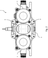
- Figs. 1 and 2 show side and front views of an electromechanical actuator drive system comprising two motors linked to a single, common, drive output.
- the drive system 2 comprises first and second electric motors 4, 6 connected to respective inputs of a first, combined input gearbox 8.
- the combined input gearbox combines the torque input of the motors to provide a single output.
- the system further includes a second gearbox 10 connected to the output of the combined input gearbox 8, which provides the drive system output 12.
- the drive system 2 is configured such that either of the first or second motors 4, 6 can drive the drive system output 12 in either rotational direction, depending on the mode of operation of the drive system 2, to provide driving actuation in two directions.
- the same drive system 2 can be operated such that the first and second motors 4, 6 both drive the drive system output 12 together to provide a combined torque in either rotational direction.
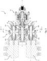
- Fig. 3 is a section plan view of the drive system 2 along line A of Figs. 1 and 2 , showing internal features of the first and second gearboxes 8, 10.
- the first and second motors 4, 6 drive respective first and second input shafts 14, 16 positioned in the first gearbox 8.
- the first and second input shafts 14, 16 rotate about axes X and Y.
- the first and second input shafts 14, 16 in turn drive an output shaft 18 18 of the first gearbox 8 about a rotational axis Z.
- the output shaft 18 is connected to the second gearbox 10, which in turn drives the drive system output 12.
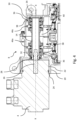
- Fig. 4 is a partial section view of the drive system 2 of Fig. 3 which shows in more detail the first motor 4 and the first input shaft 14 of the first gearbox 8.
- the first gearbox 8 comprises a receiving socket 20 in which the first motor 4 is received.
- the receiving socket 20 is defined by a socket wall extending in the direction of the axis X.
- the receiving socket 20 is correspondingly shaped to an outer periphery 22 of the motor 4, and the motor 4 is disposed in the receiving socket 20 in a press-fit.
- the motor comprises a seal 24 positioned in a circumferential slot at the outer periphery 22, which sealingly contacts the outer periphery 24 and the socket wall.
- the outer periphery 22 of the motor 4 is generally cylindrical, and the socket wall and the seal 24 are correspondingly annular.
- the first motor 4 comprises a motor drive shaft 26 which is connected to the first input shaft 14 of the first gearbox 8.
- the first input shaft 14 comprises a tubular shape formed by an annular wall around the rotational axis X of the input shaft 14.
- the input shaft 14 extends axially from a first, connecting end 28 adjacent the motor to a distal, second end 30.
- the connecting end 28 of the input shaft 14 comprises an opening 32 circumscribed by a radially constricted portion of the annular wall. The radially constricted portion is correspondingly shaped to the motor drive shaft 26, which is received in the opening 32.
- the motor drive shaft 26 is connected to the input shaft 14 such that the motor drive shaft 26 can drive the first input shaft 14 in either rotational direction.
- the motor drive shaft 26 and opening 32 may comprise a splined, or keyed fit to provide the connection and driving engagement between the motor drive shaft 26 and the input shaft 14.
- the first gearbox 8 comprises a wall 34 defining an interior space including a first cavity 40, the first input shaft 14 received in the first cavity 40.
- the gearbox wall 34 comprises shoulders 36 at an inner periphery thereof for receiving the input shaft 14.
- the input shaft 14 comprises bearings 38 to allow rotation of the input shaft 14 in-place in the cavity 40.
- the bearings 38 comprise roller elements between races, the races cooperating with the wall of the input shaft 14 and with the shoulders 36 of the first gearbox 8.
- the input shaft 14 comprises two pluralities of thrust bearings, respectively positioned at each of the first and second ends 28, 30 of the input shaft 14, to support the input shaft 14 across its length.
- the second motor 6 is connected to the second input shaft 16 of the first gearbox 8 in the same manner as the first motor 4 and first input shaft 14, and the second input shaft 16 is similarly positioned in a second cavity 42 of the first gearbox 8.
- the second motor 6 and second input shaft 16 comprise all of the same features described above in relation to the first motor 4 and first input shaft 14.
- the two sets of features are substantially identical.
- the first and second motors 4, 6 in the example shown comprise the same type of motor, with the same dimensions and drive characteristics, such that the two motors 4, 6 can each independently provide the entire drive required of the system 2.
- the drive characteristic of each motor may be defined as the maximum speed and torque capability of the motor and/or the relationship of speed to torque output by the motor.
- the second motor 6 may be smaller and/or have a different drive characteristic than the first motor 4, which may reduce space and weight of the overall assembly while still allowing the second motor 6 to act as a backup or auxiliary to the first motor 4.
- the output shaft 18 is received in a third cavity 44 in the first gearbox 8.
- the output shaft 18 is centrally located in the first gearbox 8, with the two inputs shafts 14, 16 disposed on laterally opposite sides of the output shaft 18.
- the first and second cavities 40, 42 receiving the input shafts 14, 16 are disposed on opposed lateral sides of the third cavity 44.
- the first, second and third cavities 40, 42, 44 are linked together to form a single interior space, circumscribed by the wall 34 of the first gearbox 8.
- the wall 34 defines a substantially fluid-tight space, to best retain any lubricant within the drive system 2.
- the first, second and third cavities 40, 42, 44 are fluidly linked, allowing lubricant to flow within substantially the whole interior space.
- the interiors of the first and second gearboxes 8, 10 may also be fluidly linked, so that lubricant is shared between the interiors and so that unnecessary seals may be avoided.
- the first and second input shafts 14, 16 are each drivingly connected to the output shaft 18 via a plurality of overrunning clutches 46a-d positioned on each of the input shafts 14, 16.
- the overrunning clutches 46a-d are each configured to turn with the respective one of the input shafts 14, 16 when the shaft rotates in one rotational direction (a driving direction), and to allow free-running of the input shaft 14, 16 in another rotational direction (an overrunning direction).
- the overrunning clutches 46a-d thereby transfer torque from the input shaft to the output shaft 18 only in one of the two rotational directions.
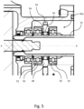
- Fig. 5 is a partial, detail view showing a first overrunning clutch 46a of the first input shaft 14 in more detail.
- the overrunning clutch 46a comprises an annular body 48 encircling and coaxial with the first input shaft 14.
- the annular body comprises shoulders 50 extending axially outward therefrom in each direction.
- the shoulders define bearing recesses on either axial side of the overrunning clutch 46a, in which thrust bearings 52 are received. Races of the bearing cooperate with the shoulders 50 and with a surface of the first input shaft 14, supporting the annular body 48 at either axial side while allowing free rotation of the overrunning clutch 46a around the input shaft 14.
- the overrunning clutch 46a comprises a geared portion 54 with a plurality of gear teeth disposed around an outer circumference of the annular body 48 for meshing with a drive gear of the output shaft 18, as will be described further below.
- Each of the first and second input shafts 14, 16 comprises respective first overrunning clutches 46a, 46b and second overrunning clutches 46c, 46d, which each comprise all of the features described above in relation to the first overrunning clutch 46a on the first input shaft 14.
- Each of the first overrunning clutches 46a, 46b are axially spaced from the respective second overrunning clutches 46c, 46d along the input shafts 14, 16, with the first overrunning clutches 46a, 46b positioned towards the connecting end 28 of the input shafts 14, 16, and the second overrunning clutches 46c, 46d generally towards the distal end 30.
- the first overrunning clutches 46a, 46b are configured to engage with or allow free-running of the input shaft 14, 16 in different rotational directions to the second overrunning clutches 46c, 46d. That is, each of the first overrunning clutches 46a, 46b engages with the input shaft 14, 16 in a first rotational direction (for example, a clockwise direction) of the input shaft 14, 16, and free-wheels relative to the input shaft 14, 16 in a second rotational direction (for example, an anti-clockwise direction). Each of the second overrunning clutches 46c, 46d engages with the input shaft 14, 16 in the second rotational direction, and free-wheels relative to the input shaft 14, 16 in the first rotational direction.
- first rotational direction for example, a clockwise direction
- second overrunning clutches 46c, 46d engages with the input shaft 14, 16 in the second rotational direction, and free-wheels relative to the input shaft 14, 16 in the first rotational direction.
- the first and second overrunning clutches 46b, 46d of the second input shaft 16 are aligned in an axial direction with the first and second overrunning clutches 46a, 46c of the first input shaft 14, with the aligned one of the overrunning clutches 46a-d sharing the same rotational driving direction.
- the overrunning clutches 46a-d comprise first and second sprag clutches, each comprising a plurality of sprag elements 56.
- the sprag elements 56 of the first and second sprag clutches 46a-d are positioned within the respective outer race of each of the overrunning clutches.
- the sprag elements 56 are connected to an inner surface 58 of the annular body 48 such that they are able to flex in-place between a slip position and a drive position.
- a contact surface of each of the sprag elements 56 contacts the wall of the input shaft 14, 16.
- the sprag elements 56 of the first sprag clutch 46a, 46b are forced into a drive position, and form a driving engagement between the input shaft 14, 16 and the annular body 48.
- the sprag elements 56 of the first sprag clutch 46a, 46b are allowed to return to a slip position, and the input shaft 14, 16 rotates freely within a slip contact of the sprag elements 56.
- the sprag elements 56 in the second sprag clutch 46c, 46d are positioned in a circumferentially mirrored direction to the sprag elements 56 of the first sprag clutch 46a, 46b.
- the sprag elements 56 function in the same manner as those in the first sprag clutch 46a, 46b, except in the opposed rotational directions.
- Fig. 6 is a partial section view of the drive system 2 of Fig. 3 showing features of the output shaft 18 in greater detail.
- the output shaft 18 comprises first and second drive gears 60, 62 which are each configured to receive torque from either of the first and second input shafts 14, 16.
- the first and second drive gears 60, 62 are each configured to rotate freely around the output shaft 18 in one mode of operation, and to be engaged with the output shaft 18 via an output clutch 64 in another mode of operation, driving the output shaft 18.
- the first and second drive gears 60, 62 each comprise an annular body, with gear teeth 66 arranged around a radially outer surface, and a central bore defined by a radially inner surface which is spaced from the output shaft 18.
- the gear teeth 66 of the first and second drive gears 60, 62 mesh with gear teeth 54 of the overrunning clutches 46a-d of the first and second input shafts 14, 16.
- a first drive gear 60 is positioned towards a first axial end 68 of the output shaft 18 closest to the first and second motors 4, 6, aligned and meshed with the first overrunning clutches 46 of both of the first and second input shafts 14, 16.
- a second drive gear 62 is positioned towards a second axial end 70 of the output shaft 18 closest to an output of the first gearbox 8, aligned and meshed with the second overrunning clutches 46a-d of both of the first and second input shafts 14, 16.
- overrunning clutches 46a-d allows either of the first and second input shafts 14, 16 to drive the output shaft 18 while preventing binding of the drive gears 60, 62.
- driving the first input shaft 14 in the first direction transmits torque through the first overrunning clutch 46a to the first drive gear 60, causing the output shaft 18 to rotate in the opposing second direction.
- the first drive gear 60 is also meshed with the first overrunning clutch 46b of the second input shaft 16, but the first overrunning clutch 46b of the second input shaft 16 is allowed to turn freely when the first overrunning clutch 46a of the first input shaft 14 is driving. In this manner, movement of the drive gear 60 is not seized despite connection to both of the first overrunning clutches 46a, 46b.
- the first motor 4 can drive the output shaft 18 while the second motor 6 is stationary or running under-speed compared to the first motor 4.
- a similar function occurs if, vice-versa, the second input shaft 16 is driven by the second motor 6 to rotate more quickly than the first input shaft 14.
- the first overrunning clutch 46b on the second input shaft 16 drives the first drive gear 60, and the first overrunning clutch 46a on the first input shaft 14 turns freely.
- the output shaft 16 can receive driving input from either of the first of second motors 4, 6 via the first and second input shafts 14, 16. This allows, for example, one of the first and second motors 4, 6 to be provided as a primary motor, and another to be retained as a secondary or redundant motor for the event of a failure of the primary motor.
- the arrangement of the system 2 described above is such that the speed of drive system output 12 is the same when driven by either motor.
- first and second input shafts 14, 16 are driven at substantially the same speed, both will drive the first drive gear 60 and transfer torque to the output shaft 18.
- the torque of the output shaft 18 is a combination of the torques of the input shafts 14, 16. Any incidental or intermittent differences in the speed of the first and second motors 4, 6 and the input shafts 14, 16 which might otherwise cause binding or seizure of the drive gear 60 is instead compensated for by the presence of the overrunning clutches 46.
- the output shaft 18 is drivable in the first rotational direction by either of the first and second inputs shafts 14, 16 via the second drive gear 62 in a similar manner to that described above.
- Rotating either of the first or second input shafts 14, 16 in the second direction engages the respective second overrunning clutch 46c, 46d, transferring torque to the second drive gear 62 and rotating the output shaft 18 in the first direction.
- the first and second motors 4, 6 can be used as primary and secondary motors or can provide a combined torque output.
- additional motors and input shafts around the output shaft may comprise overrunning clutches which mesh with the drive gears in a similar manner to that described in relation to the first and second motors and input shafts.
- Such an arrangement would function similarly to that described above, with each motor able to drive the output shaft independently or together to provide a combined torque output.
- a clutch connection or output clutch 64 is provided between the first and second drive gears 60, 62 and the output shaft 18.
- the output clutch 64 selectively engages one or other of the drive gears with the output shaft 18, allowing transfer of torque from the first drive gear 60 to the output shaft 18 in a first mode of operation, and from the second drive gear 62 to the output shaft 18 in a second mode of operation.
- the output clutch 64 includes a driven clutch part 72, which is fixedly attached to or formed integrally with the output shaft 18, and a pair of driving clutch parts 74, 76, which independently and selectively bind with the driven clutch part 72 in order to transfer torque from the drive gears 60, 62 to the output shaft 18.
- the driving clutch parts 74, 76 are moveable axially into and out of contact with the driven clutch part 72, to engage or disengage depending on the mode of operation.
- the output clutch 64 comprises a first driving clutch part 74 associated with the first drive gear 60 and a second driving clutch part 76 associated with the second drive gear 62.
- the clutch connection is a cone clutch.
- the driven clutch part 72 is centrally located on the output shaft 18, and comprises a body with a surface 78 defining two male cone elements facing opposed axial directions.
- the driving clutch parts 74, 76 each comprise a body with a surface 80 defining female cone elements, facing towards the respective male cone elements and correspondingly shaped to receive the male cone elements.
- the driving clutch parts 74, 76 are configured to be axially moveable along the output shaft 18, to move into and out of contact with the driven clutch part 72, and selectively bind to the driven clutch part 72 through friction between the surfaces 78, 80 of the clutch parts.
- the driven clutch part may comprise a body with a surface defining two female cone elements
- the driving clutch parts may each comprise a body with a surface defining male cone elements.
- the function of the driven part and the driving parts is similar to that described above.
- the driving clutch parts 74, 76 are positioned around the output shaft 18 and coaxially therewith.
- the driving clutch parts 74, 76 are configured to rotate freely about the output shaft 18 when not engaged with the driven clutch part 72.
- the bodies of the driving clutch parts 74, 76 are annular, each comprising a central bore defined by a radially inner surface which is spaced from the output shaft 18.
- Fig. 7 shows a view of the output shaft 18 and driven clutch part 72 in isolation.
- the cone clutch further comprises a plurality of friction elements 82, configured to enhance friction binding between the driving clutch parts 74, 76 and the driven clutch part 72.
- the plurality of friction elements 82 comprise arc segments positioned around the circumference of the surface 78 of the driven clutch part 72 on each of the male cone elements. A circumferential separation between the arc segments forms axial oil channels 84 for lubricant flow around the friction-binding surfaces. There is also an axial separation between the friction elements of each of the two male cone surfaces, to define a circumferential oil channel 86 therebetween for similar purposes.
- the plurality of friction elements 82 each comprise a section of material which is attached to the surface 78 of the driven clutch part 72, and interfaces with the surfaces 80 of the driving clutch parts 74, 76 when the cone clutch is engaged.
- the material in one example is a hard-wearing para-aramid, for example polyparaphenylene terephthalamide.
- the plurality of friction elements 82 may instead be attached to the surfaces 80 of the driving clutch parts 74, 76, and interface with surface 78 of the driven clutch part 72 when the cone clutch is engaged.
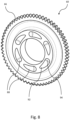
- Fig. 8 shows the first driver gear 60 in isolation.
- the first driver gear 60 comprises a plurality of ramp elements 88 shaped and configured to receive and cooperate with rolling bearings 90.
- the ramp elements are ball ramps
- the rolling bearings are ball bearings.
- the ramp elements 88 comprise depressions formed into the annular body of the drive gear 60 to form sloped surfaces.
- the ramp elements define a gradient in the axial direction, such that they extend circumferentially from an axially deeper end 92 to an axially shallower end 94, and such that they taper in width around the circumferential direction between the two ends 92. 94.
- the second drive gear 62 comprises similar ramp elements to those described.
- the ramp elements 88 of each of the drive gears 60, 62 are spaced circumferentially around the annular body of the drive gear 60, 62 on one axial side thereof.
- the ramp elements 88 of each of the drive gears 60, 62 face axially inwards along the output shaft 18, towards the driven part 72 of the output clutch 64.
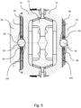
- Fig. 9 shows a view along line B of Fig. 2 , showing the ramp elements and rolling bearings in more detail.
- similar ramp elements 96 are formed on one axial side of each of the driving clutch parts 74, 76 of the output clutch 64.
- the ramp elements 96 of the driving clutch parts 74, 76 face axially outwards, towards the drive gears 60, 62.
- the ramp elements 96 of the driving clutch parts 74, 76 comprise all of the same features as the ramp elements 88 of the drive gears 60, 62, but are mirrored to those of the drive gears 60, 62, so that the sloped surfaces extend in an opposite direction circumferentially.
- the driver gears 60, 62 and driving clutch parts 74, 76 comprise a corresponding number of ramp elements 88, 96, so that each ramp element 88 on each drive gear 60, 62 has a counterpart ramp element 96 on the driving clutch part 74, 76.
- a ball bearing 90 is received between each ramp element 88 of the driver gear 74, 76 and the respective counterpart ramp element 96 of the driving clutch part 74, 76.
- the ball bearings 90 act to transform a portion of rotational force applied to the drive gear 60, 62 into an axial movement of the driving clutch part 74, 76, into engagement with the driven clutch part 72.
- the drive gear 60, 62 When one of the drive gears 60, 62 is driven by one of the overrunning clutches 46a-d of the input shafts 14, 16, the drive gear 60, 62 initially rotates relative to the driving clutch part 74, 76.
- the ramp elements 88 of the drive gear 60, 62 force the ball bearing 90 circumferentially along the sloped surfaces of the ramp elements 88, and thereby force the ball bearings 90 in an axial direction towards the driving clutch part 74, 76.
- the ball bearing 90 bears against the sloped surface of the ramp element 96 on the driving clutch part 74, 76.
- the driving clutch part 74, 76 With the output clutch 64 engaged, the output shaft 18 rotates with the drive gear 60, 62.
- the ball bearing 90 is free to return along the sloped surfaces of the ramp elements 88, 96, and the driving clutch part 74, 76 is free to move axially out of engagement with the driven clutch part 72.
- the ramp elements may cooperate with a rolling element other than a ball bearing, such as a cylindrical bearing.
- the configuration of the output clutch 64 is such that rotation of either one of the drive gears 60, 62 automatically engages the corresponding driving clutch part 74, 76 with the driven clutch part 72. That is, the driving clutch parts 74, 76 engage selectively based on the received rotational input.
- This mechanical automation may reduce a complexity of the output clutch 64 as compared to a manual or electronically automated clutch, saving space and weight in the system.
- Fig. 10 shows a section view of the drive system 2 along line C of Figs. 1 and 3 , showing one of a pair of bearing cages 98 which may be positioned around the output shaft 18 to help regulate movement of the ball bearings 90 within the ramp elements 88, 96.
- First and second bearing cages 98 are provided between each of the first and second drive gears 60, 62 and the adjacent one of driving clutch parts 74, 76.
- the bearing cages 98 each comprise a disk with an annular body and a central bore defined by a radially inner surface which is spaced from the output shaft 18.
- a plurality of openings 100 are formed in the body of the disk of the bearing cage 98, extending entirely through the body in the axial direction.
- the bearing cages 98 are positioned alongside the drive gears 60, 62 and driving clutch parts 74, 76.
- the openings of the bearing cages 98 are shaped to receive the ball bearings 90 so that the ball bearings 90 sit within the openings 100 and between the cooperating ramp elements 88, 96 of the adjacent drive gear 60, 62 and driving clutch part 74, 76.
- the bearing cages 98 act to constrain the circumferential position and separation of the ball bearings 90, which in turn regulates the axial movement of all of the ball bearings 90 about the circumference.
- the cages 98 may thereby provide a more robust and consistent axial actuation of the driving clutch parts 74, 76.
- Fig. 11 shows a section view of the drive system 2 along line D of Figs. 1 and 3 , showing a drag disk arrangement 102 which may function to improve the responsiveness of the driving clutch parts and roller elements to torque input.
- Fig. 12 shows a partial detail view of Fig. 3 , showing features of the drag plate arrangement 102.
- the drag disk arrangement 102 comprises a static drag plate 104 which is fixedly attached to a static portion of the first gearbox so that the plate is held against rotation, and a pair of drag pins 106, each attached to a respective one of the driving clutch parts 74, 76.
- the drag pins 106 each comprise a spring 108 which bears the pin axially away from the driving clutch part 74, 76 to which it is attached.
- the drag pins 106 each bear against one of the axial sides of the drag plate 104 so as to generate a generally constant, relatively low level of drag torque from friction between the drag plate 104 and the drag pins 106.
- the springs 108 keep the drag pins 106 in contact with the drag plate 104 both when the respective driving clutch part 74, 76 is separated from the driven clutch part 72, and when it is engaged.
- the drag plate arrangement 102 generates a constant, low level of torque drag which must be overcome by either driving clutch part 74, 76 when it is initially driven in rotation.
- the torque drag limits a rotation of the driving clutch part 74, 76 slightly relative to the respective drive gear 60, 62, so that initial rotation of the drive gear 60, 62 will force roller bearings along their ramp elements between the drive gear 60, 62 and the driving clutch part 74, 76, rather than only transferring torque to a free-wheeling driving clutch part 74, 76.
- the low level of torque drag thereby ensures that the initial rotation of the drive gear 60, 62 causes axial movement and proper engagement of the driving clutch part 74, 76.
- the low level of drag on the driving clutch parts for actuation of the roller bearings may instead be provided by other aspects of the design, the use of a drag disk arrangement may allow a fine-tuning of the level of drag via the drag pins. By properly tuning the low level of drag, good function of the driving clutch parts can be ensured without inducing unnecessary inefficiency.
- Fig. 13 shows a partial detail view of Fig. 3 , showing internal features of the second gearbox 10 in more detail.
- the second gearbox 10 is configured to provide additional reduction in speed from the output of the first gearbox 8 to a drive system output 12 of the overall drive system 2.
- the second gearbox 10 comprises an input shaft 110 for receiving torque from the output shaft 18 of the first gearbox 8.
- the output shaft 18 and the second gearbox input shaft 110 comprise a connection so as to rotate together.
- the connection comprises a quill shaft 112 which is received in respective openings formed in axial ends of the output shaft 18 and the input shaft 110.
- the input shaft 110 comprises gear teeth 114 arranged around an annular periphery.
- the second gearbox 10 comprises an elliptical gear system 116 to provide sufficient reduction of speed in a relatively small space.
- the gear system 116 comprises a first set of planetary gears 118 which are meshed with the gear teeth 116 of the input shaft 110, such that the input shaft 110 acts as a sun gear.
- the gear system further comprises a ring gear 120 encircling the first set of planetary gears 118 and fixed to an inner periphery of the second gearbox 10. Rotation of the input shaft 110 in a first direction drives rotation of the first set of planetary gears 118 in the same direction within the fixed ring gear 120.
- the first set of planetary gears 118 are held by a first gear carrier 122, which comprises pins 124, each pin 124 positioned in one of the first set of planetary gears 118 so that the carrier 120 rotates with the planetary gears 118.
- the carrier 122 comprises a carrier shaft section 126 extending axially from the pins 124 to provide the rotational output of the first set of planetary gears 118.
- the gear system 116 is a two-stage elliptical gear system for providing further reduction of speed in a space-efficient arrangement.
- the gear system further comprises a second set of planetary gears 130 arranged around the carrier shaft 126 of the first gear carrier 122, axially adjacent to the first set of planetary gears 116.
- the carrier shaft 126 comprises gear teeth 128 about an outer periphery, which mesh with teeth of the second set of planetary gears 130.
- the second set of planetary gears 130 rotate within the same ring fixed gear 120 as the first set of planetary gears 118.
- a second gear carrier 132 comprises pins 134, each pin 134 positioned in one of the second set of planetary gears 130 so that the second gear carrier 132 rotates with the second set of planetary gears 130.
- the second carrier 132 also comprises a shaft section 136 extending axially from the pins 134 to provide the rotational output.
- the second gearbox 10 comprises a second gearbox output shaft 138 which is driven by the output of the gear system.
- the output shaft 138 comprises a splined connection to the shaft section 136 of the second carrier 132.
- the output shaft 138 acts as the drive system output 12, providing the output drive of the overall actuator drive system 2.
- the first gearbox 8 provides some reduction of speed, such that the output shaft 18 of the first gearbox 8 rotates more slowly than the input shaft or shafts 14, 16, which rotate at the driving speed of the motors 4, 6.
- the second gearbox 10 provides a greater reduction in speed than the first gearbox 8, to further reduce the overall speed reduction of the system between the motors 4, 6 and the drive system output 12.
- the second gearbox 10 may have a gear ratio of greater than five times that of the first gearbox 8.
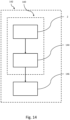
- the actuator drive system 2 may form part of an actuator assembly 140, with the drive system 2 arranged to drive an actuator 144 such as a linear actuator.
- an actuator 144 such as a linear actuator.
- the above-described features of the drive system 2, with two motors configured to provide dual or redundant output in two rotational directions, may be particularly useful in the context of driving such an actuator, which can require robust operation in two actuation directions.
- the actuator drive system 2 may further form part of a control surface assembly 142 for an aircraft.
- the drive system 2 is arranged to drive the actuator 144 and the actuator 144 is arranged to move the control surface 146.
- the above-described features of the drive system 2 may be particularly useful in the context of driving an aircraft control surface, in which redundant operation is important for safety reasons, space and weight considerations are especially important, and dual-motor operation can be used to provide additional torque in some situations such as mechanical limit cases or emergency operation.
Landscapes
- Engineering & Computer Science (AREA)
- General Engineering & Computer Science (AREA)
- Mechanical Engineering (AREA)
- Automation & Control Theory (AREA)
- Aviation & Aerospace Engineering (AREA)
- Transmission Devices (AREA)
Abstract
Description
- The present invention relates to an electromechanical drive system with dual electric motor drive, in particular for use as or as part of an electrically driven actuator or actuation system on an aircraft.
- Actuators are used in various parts of aircraft systems to move mechanical elements of the aircraft, for example control surfaces, between two positions. This actuation is often driven, directly or indirectly, by motors.
- Actuators and actuation systems in aircraft are often considered safety critical, such that secondary or redundant drive channels must be provided in case of failure of a primary drive channel. There is also a need for both primary and secondary systems to be robust.
- In aircraft systems, there is a further need for any actuator and associated drive systems to be compact for packaging reasons, and to be low-weight. It is also desirable for actuators and drive systems to have as little complexity as possible, which can reduce the chance of failure and reduce maintenance requirements.
- In the present disclosure, there is provided a dual motor electric drive system which provides redundancy against motor drive channel failures and facilitates dual channel electric motor drives in either active-active (both motors driving) or active-standby (one motor driving) modes, while also being robust, efficiently packaged, and having a reduced complexity compared to other arrangements.
- According to a first aspect of the present disclosure, there is provided a drive system for an actuator or actuation system, the drive system comprising first and second motors, and first and second input shafts connected to be driven by the respective first and second motors. Each of the first and second input shafts comprise a first overrunning clutch configured to rotate with the input shaft in a first direction, anda second overrunning clutch configured to rotate with the input shaft in a second direction. The drive system further comprises a first drive gear configured to be driven by either one of the first overrunning clutches, and a second drive gear configured to be driven by either one of the second overrunning clutches. The drive system further comprises an output shaft and an output clutch associated with the output shaft, wherein the output clutch and output shaft are arranged to be driven by the first drive gear in a first mode of operation of the drive system and be driven by the second drive gear in a second mode of operation of the drive system.
- In an active-active mode, the two motors are active and the drive system combines the input of the motors into a single output, so that an output torque is the sum of the torque provided by each motor.
- In an active-standby mode, the drive system delivers the torque provided by one, active motor to the output whilst allowing another, standby motor to remain stationary. In the case that the input of the active motor fails, the drive system connects the input of the standby motor to the output. In the case of such a failure mode, the drive system will drive the output irrespective as to whether the failure of the input is due to a mechanical seizure within the motor or a loss of power delivered to the motor. The drive system is therefore robust against a failure of either motor or associated electric drive channel.
- The described functionality of the drive system is provided whether the drive system is commanded to drive in a clockwise or anticlockwise direction of output rotation.
- The drive system is a significant improvement over a drive system arrangements that may use a differential gearbox to couple two motor drive channels to a single output. Such a differential arrangement may have a greatly increased complexity, for example requiring additional electrically actuated brakes to earth the differential gearbox, additional electrical interfaces, additional electrical power and additional command signals.
- In a further embodiment of the drive system described above, the output shaft defines an axis of rotation, and the output clutch comprises a driven clutch part connected to the output shaft and first and second driving clutch parts which are axially moveable into and out of engagement with the driven clutch part.
- In a further embodiment of any of the above, the first and second drive gears are each positioned adjacent to a respective one of the first and second driving clutch parts, each of the first and second drive gears and driving clutch parts comprise a plurality of ramp elements, and a plurality of rolling elements are positioned between the ramp elements of adjacent ones of the first and second drive gears and driving clutch parts.
- In a further embodiment of any of the above, the plurality of rolling elements comprise a plurality of ball bearings.
- In a further embodiment of any of the above, the drive system further comprises first and second bearing cages, each bearing cage comprising a plurality of openings, the plurality of ball bearings received within the plurality of openings.
- In a further embodiment of any of the above, the output clutch comprises a cone clutch comprising a pair of male cone elements and a pair of female cone elements, one of the male cone elements in frictional contact with one of the female cone elements in the first mode of operation, and the other one of the male cone elements in frictional contact with the other one of the female cone elements in the second mode of operation.
- In a further embodiment of any of the above, the pair of male cone elements form the driven clutch part, and the pair of female cone elements form the first and second driving clutch parts.
- In a further embodiment of any of the above, the first and second input shafts define axes of rotation which are parallel to the axis of the output shaft.
- In a further embodiment of any of the above, each of the first overrunning clutches comprises gear teeth formed around an outer periphery, the gear teeth meshing with gear teeth of the first drive gear, and each of the second overrunning clutches comprises gear teeth formed around an outer periphery, the gear teeth meshing with gear teeth of the second drive gear.
- In a further embodiment of any of the above, each of the first overrunning clutches and each of the second overrunning clutches comprises a sprag clutch, each having a plurality of sprag elements in contact with the respective input shaft.
- In a further embodiment of any of the above, the drive system further comprises a dynamic drag clutch comprising a brake wheel connected to the output shaft and at least one drag pin in contact with the brake wheel.
- In a further embodiment of any of the above, the drive system further comprises an epicyclic gearbox, the output shaft arranged to drive an input of the epicyclic gearbox.
- In a further embodiment of any of the above, the first and second motors comprise the same maximum speed and torque capability and/or the same relationship of speed to torque.
- According to a further aspect of the present disclosure, there is provided an actuator assembly for a control surface of an aircraft, the actuator assembly comprising an actuator and a drive system according to any of the above embodiments, the drive system connected to drive the actuator.
- In a further embodiment of the above, the actuator is a linear actuator.
- These and other features of the disclosure can be best understood from the following description and drawings.
-
-
Figure 1 shows a side view of a drive system according to an aspect of the disclosure. -
Figure 2 shows a front view of the drive system ofFigure 1 . -
Figure 3 shows a section plan view of the drive system ofFigures 1 and2 along the line A. -
Figure 4 shows a partial, detail view of one part of the drive system ofFigure 3 . -
Figure 5 shows a partial, detail view of one part of the drive system ofFigure 4 . -
Figure 6 shows another partial, detail view of another part of the drive system ofFigure 3 . -
Figure 7 shows an isolated perspective view of anoutput shaft 18 of the drive system ofFigure 3 . -
Figure 8 shows an isolated perspective view of a drive gear of the drive system ofFigure 3 . -
Figure 9 shows a section front view of the drive system ofFigure 2 along the line B. -
Figure 10 shows a partial section side view of the drive system ofFigure 9 along the line C. -
Figure 11 shows a section front view of the drive system ofFigures 1 and3 along the line D. -
Figure 12 shows another partial, detail view of another part of the drive system ofFigure 3 . -
Figure 13 shows another partial, detail view of another part of the drive system ofFigure 3 . -
Figure 14 shows an aircraft control surface assembly. -
Figs. 1 and2 show side and front views of an electromechanical actuator drive system comprising two motors linked to a single, common, drive output. Thedrive system 2 comprises first and secondelectric motors input gearbox 8. The combined input gearbox combines the torque input of the motors to provide a single output. The system further includes asecond gearbox 10 connected to the output of the combinedinput gearbox 8, which provides thedrive system output 12. - The
drive system 2 is configured such that either of the first orsecond motors drive system output 12 in either rotational direction, depending on the mode of operation of thedrive system 2, to provide driving actuation in two directions. In addition, thesame drive system 2 can be operated such that the first andsecond motors drive system output 12 together to provide a combined torque in either rotational direction. -
Fig. 3 is a section plan view of thedrive system 2 along line A ofFigs. 1 and2 , showing internal features of the first andsecond gearboxes second motors second input shafts first gearbox 8. The first andsecond input shafts second input shafts output shaft 18 18 of thefirst gearbox 8 about a rotational axis Z. Theoutput shaft 18 is connected to thesecond gearbox 10, which in turn drives thedrive system output 12. -
Fig. 4 is a partial section view of thedrive system 2 ofFig. 3 which shows in more detail thefirst motor 4 and thefirst input shaft 14 of thefirst gearbox 8. Thefirst gearbox 8 comprises a receivingsocket 20 in which thefirst motor 4 is received. The receivingsocket 20 is defined by a socket wall extending in the direction of the axis X. The receivingsocket 20 is correspondingly shaped to anouter periphery 22 of themotor 4, and themotor 4 is disposed in the receivingsocket 20 in a press-fit. The motor comprises aseal 24 positioned in a circumferential slot at theouter periphery 22, which sealingly contacts theouter periphery 24 and the socket wall. Theouter periphery 22 of themotor 4 is generally cylindrical, and the socket wall and theseal 24 are correspondingly annular. - The
first motor 4 comprises amotor drive shaft 26 which is connected to thefirst input shaft 14 of thefirst gearbox 8. Thefirst input shaft 14 comprises a tubular shape formed by an annular wall around the rotational axis X of theinput shaft 14. Theinput shaft 14 extends axially from a first, connectingend 28 adjacent the motor to a distal,second end 30. The connectingend 28 of theinput shaft 14 comprises anopening 32 circumscribed by a radially constricted portion of the annular wall. The radially constricted portion is correspondingly shaped to themotor drive shaft 26, which is received in theopening 32. - The
motor drive shaft 26 is connected to theinput shaft 14 such that themotor drive shaft 26 can drive thefirst input shaft 14 in either rotational direction. Themotor drive shaft 26 andopening 32 may comprise a splined, or keyed fit to provide the connection and driving engagement between themotor drive shaft 26 and theinput shaft 14. - The
first gearbox 8 comprises awall 34 defining an interior space including afirst cavity 40, thefirst input shaft 14 received in thefirst cavity 40. Thegearbox wall 34 comprisesshoulders 36 at an inner periphery thereof for receiving theinput shaft 14. Theinput shaft 14 comprisesbearings 38 to allow rotation of theinput shaft 14 in-place in thecavity 40. Thebearings 38 comprise roller elements between races, the races cooperating with the wall of theinput shaft 14 and with theshoulders 36 of thefirst gearbox 8. Theinput shaft 14 comprises two pluralities of thrust bearings, respectively positioned at each of the first and second ends 28, 30 of theinput shaft 14, to support theinput shaft 14 across its length. - Returning to
Fig. 3 , thesecond motor 6 is connected to thesecond input shaft 16 of thefirst gearbox 8 in the same manner as thefirst motor 4 andfirst input shaft 14, and thesecond input shaft 16 is similarly positioned in asecond cavity 42 of thefirst gearbox 8. Thesecond motor 6 andsecond input shaft 16 comprise all of the same features described above in relation to thefirst motor 4 andfirst input shaft 14. In the illustrated example, the two sets of features are substantially identical. In particular, the first andsecond motors motors system 2. The drive characteristic of each motor may be defined as the maximum speed and torque capability of the motor and/or the relationship of speed to torque output by the motor. - In other alternatives, the
second motor 6 may be smaller and/or have a different drive characteristic than thefirst motor 4, which may reduce space and weight of the overall assembly while still allowing thesecond motor 6 to act as a backup or auxiliary to thefirst motor 4. - The
output shaft 18 is received in athird cavity 44 in thefirst gearbox 8. Theoutput shaft 18 is centrally located in thefirst gearbox 8, with the twoinputs shafts output shaft 18. The first andsecond cavities input shafts third cavity 44. The first, second andthird cavities wall 34 of thefirst gearbox 8. Thewall 34 defines a substantially fluid-tight space, to best retain any lubricant within thedrive system 2. The first, second andthird cavities second gearboxes - The first and
second input shafts output shaft 18 via a plurality of overrunningclutches 46a-d positioned on each of theinput shafts clutches 46a-d are each configured to turn with the respective one of theinput shafts input shaft clutches 46a-d thereby transfer torque from the input shaft to theoutput shaft 18 only in one of the two rotational directions. -
Fig. 5 is a partial, detail view showing a first overrunning clutch 46a of thefirst input shaft 14 in more detail. The overrunning clutch 46a comprises anannular body 48 encircling and coaxial with thefirst input shaft 14. The annular body comprisesshoulders 50 extending axially outward therefrom in each direction. The shoulders define bearing recesses on either axial side of the overrunning clutch 46a, in whichthrust bearings 52 are received. Races of the bearing cooperate with theshoulders 50 and with a surface of thefirst input shaft 14, supporting theannular body 48 at either axial side while allowing free rotation of the overrunning clutch 46a around theinput shaft 14. The overrunning clutch 46a comprises a gearedportion 54 with a plurality of gear teeth disposed around an outer circumference of theannular body 48 for meshing with a drive gear of theoutput shaft 18, as will be described further below. - Each of the first and
second input shafts first overrunning clutches second overrunning clutches first input shaft 14. Each of thefirst overrunning clutches second overrunning clutches input shafts first overrunning clutches end 28 of theinput shafts second overrunning clutches distal end 30. Thefirst overrunning clutches input shaft second overrunning clutches first overrunning clutches input shaft input shaft input shaft second overrunning clutches input shaft input shaft clutches second input shaft 16 are aligned in an axial direction with the first andsecond overrunning clutches first input shaft 14, with the aligned one of the overrunningclutches 46a-d sharing the same rotational driving direction. - In the example shown, the overrunning
clutches 46a-d comprise first and second sprag clutches, each comprising a plurality ofsprag elements 56. Thesprag elements 56 of the first andsecond sprag clutches 46a-d are positioned within the respective outer race of each of the overrunning clutches. Thesprag elements 56 are connected to aninner surface 58 of theannular body 48 such that they are able to flex in-place between a slip position and a drive position. A contact surface of each of thesprag elements 56 contacts the wall of theinput shaft input shaft sprag elements 56 of the first sprag clutch 46a, 46b are forced into a drive position, and form a driving engagement between theinput shaft annular body 48. When theinput shaft sprag elements 56 of the first sprag clutch 46a, 46b are allowed to return to a slip position, and theinput shaft sprag elements 56. Thesprag elements 56 in the second sprag clutch 46c, 46d are positioned in a circumferentially mirrored direction to thesprag elements 56 of the first sprag clutch 46a, 46b. In the second sprag clutch 46c, 46d, thesprag elements 56 function in the same manner as those in the first sprag clutch 46a, 46b, except in the opposed rotational directions. -
Fig. 6 is a partial section view of thedrive system 2 ofFig. 3 showing features of theoutput shaft 18 in greater detail. Theoutput shaft 18 comprises first and second drive gears 60, 62 which are each configured to receive torque from either of the first andsecond input shafts output shaft 18 in one mode of operation, and to be engaged with theoutput shaft 18 via anoutput clutch 64 in another mode of operation, driving theoutput shaft 18. - The first and second drive gears 60, 62 each comprise an annular body, with
gear teeth 66 arranged around a radially outer surface, and a central bore defined by a radially inner surface which is spaced from theoutput shaft 18. Thegear teeth 66 of the first and second drive gears 60, 62 mesh withgear teeth 54 of the overrunningclutches 46a-d of the first andsecond input shafts - A
first drive gear 60 is positioned towards a firstaxial end 68 of theoutput shaft 18 closest to the first andsecond motors second input shafts second drive gear 62 is positioned towards a secondaxial end 70 of theoutput shaft 18 closest to an output of thefirst gearbox 8, aligned and meshed with thesecond overrunning clutches 46a-d of both of the first andsecond input shafts - The arrangement of overrunning
clutches 46a-d allows either of the first andsecond input shafts output shaft 18 while preventing binding of the drive gears 60, 62. For example, driving thefirst input shaft 14 in the first direction transmits torque through the first overrunning clutch 46a to thefirst drive gear 60, causing theoutput shaft 18 to rotate in the opposing second direction. Thefirst drive gear 60 is also meshed with the first overrunning clutch 46b of thesecond input shaft 16, but the first overrunning clutch 46b of thesecond input shaft 16 is allowed to turn freely when the first overrunning clutch 46a of thefirst input shaft 14 is driving. In this manner, movement of thedrive gear 60 is not seized despite connection to both of thefirst overrunning clutches first motor 4 can drive theoutput shaft 18 while thesecond motor 6 is stationary or running under-speed compared to thefirst motor 4. - A similar function occurs if, vice-versa, the
second input shaft 16 is driven by thesecond motor 6 to rotate more quickly than thefirst input shaft 14. In this mode, the first overrunning clutch 46b on thesecond input shaft 16 drives thefirst drive gear 60, and the first overrunning clutch 46a on thefirst input shaft 14 turns freely. - The
output shaft 16 can receive driving input from either of the first ofsecond motors second input shafts second motors - In addition, the arrangement of the
system 2 described above is such that the speed ofdrive system output 12 is the same when driven by either motor. This contrasts, for example, to a differential gearbox arrangement with two motors, where output speed of the gearbox is proportionate to an average of the input speeds, so that running only one motor causes an output to rotate at half of the regular speed. - In another mode of function, if the first and
second input shafts first drive gear 60 and transfer torque to theoutput shaft 18. The torque of theoutput shaft 18 is a combination of the torques of theinput shafts second motors input shafts drive gear 60 is instead compensated for by the presence of the overrunning clutches 46. - In addition to being drivable in the second rotational direction as described above, the
output shaft 18 is drivable in the first rotational direction by either of the first andsecond inputs shafts second drive gear 62 in a similar manner to that described above. Rotating either of the first orsecond input shafts second drive gear 62 and rotating theoutput shaft 18 in the first direction. Again, the first andsecond motors - While the illustrated arrangement and present description relate to an example where two motors are used to drive an output, the same features may be applied to an embodiment of a drive system where the input of any number of motors may be combined to provide a single output. In such examples, additional motors and input shafts around the output shaft may comprise overrunning clutches which mesh with the drive gears in a similar manner to that described in relation to the first and second motors and input shafts. Such an arrangement would function similarly to that described above, with each motor able to drive the output shaft independently or together to provide a combined torque output.
- To allow the
output shaft 18 to be driven in either direction by either motor, a clutch connection oroutput clutch 64 is provided between the first and second drive gears 60, 62 and theoutput shaft 18. Theoutput clutch 64 selectively engages one or other of the drive gears with theoutput shaft 18, allowing transfer of torque from thefirst drive gear 60 to theoutput shaft 18 in a first mode of operation, and from thesecond drive gear 62 to theoutput shaft 18 in a second mode of operation. - The
output clutch 64 includes a drivenclutch part 72, which is fixedly attached to or formed integrally with theoutput shaft 18, and a pair of drivingclutch parts clutch part 72 in order to transfer torque from the drive gears 60, 62 to theoutput shaft 18. The drivingclutch parts clutch part 72, to engage or disengage depending on the mode of operation. Theoutput clutch 64 comprises a first drivingclutch part 74 associated with thefirst drive gear 60 and a second drivingclutch part 76 associated with thesecond drive gear 62. - In the arrangement shown, the clutch connection is a cone clutch. The driven
clutch part 72 is centrally located on theoutput shaft 18, and comprises a body with asurface 78 defining two male cone elements facing opposed axial directions. The drivingclutch parts surface 80 defining female cone elements, facing towards the respective male cone elements and correspondingly shaped to receive the male cone elements. The drivingclutch parts output shaft 18, to move into and out of contact with the drivenclutch part 72, and selectively bind to the drivenclutch part 72 through friction between thesurfaces - In an alternative cone clutch, which is not illustrated, the driven clutch part may comprise a body with a surface defining two female cone elements, and the driving clutch parts may each comprise a body with a surface defining male cone elements. The function of the driven part and the driving parts is similar to that described above.
- The driving
clutch parts output shaft 18 and coaxially therewith. The drivingclutch parts output shaft 18 when not engaged with the drivenclutch part 72. The bodies of the drivingclutch parts output shaft 18. -
Fig. 7 shows a view of theoutput shaft 18 and drivenclutch part 72 in isolation. The cone clutch further comprises a plurality offriction elements 82, configured to enhance friction binding between the drivingclutch parts clutch part 72. The plurality offriction elements 82 comprise arc segments positioned around the circumference of thesurface 78 of the drivenclutch part 72 on each of the male cone elements. A circumferential separation between the arc segments formsaxial oil channels 84 for lubricant flow around the friction-binding surfaces. There is also an axial separation between the friction elements of each of the two male cone surfaces, to define acircumferential oil channel 86 therebetween for similar purposes. The plurality offriction elements 82 each comprise a section of material which is attached to thesurface 78 of the drivenclutch part 72, and interfaces with thesurfaces 80 of the drivingclutch parts - In an alternative, not illustrated, the plurality of
friction elements 82 may instead be attached to thesurfaces 80 of the drivingclutch parts surface 78 of the drivenclutch part 72 when the cone clutch is engaged. - Selective engagement of either one or both of the driving
clutch parts clutch part 72 may be controlled through the use of ramp elements for rolling bearings on the driver gears and the drivingclutch parts Fig. 8 shows thefirst driver gear 60 in isolation. Thefirst driver gear 60 comprises a plurality oframp elements 88 shaped and configured to receive and cooperate with rollingbearings 90. In the illustrated example, the ramp elements are ball ramps, and the rolling bearings are ball bearings. - The
ramp elements 88 comprise depressions formed into the annular body of thedrive gear 60 to form sloped surfaces. The ramp elements define a gradient in the axial direction, such that they extend circumferentially from an axiallydeeper end 92 to an axiallyshallower end 94, and such that they taper in width around the circumferential direction between the two ends 92. 94. - The
second drive gear 62 comprises similar ramp elements to those described. Theramp elements 88 of each of the drive gears 60, 62 are spaced circumferentially around the annular body of thedrive gear ramp elements 88 of each of the drive gears 60, 62 face axially inwards along theoutput shaft 18, towards the drivenpart 72 of theoutput clutch 64. -
Fig. 9 shows a view along line B ofFig. 2 , showing the ramp elements and rolling bearings in more detail. In addition to rampelements 88 formed on the drive gears 60, 62,similar ramp elements 96 are formed on one axial side of each of the drivingclutch parts output clutch 64. Theramp elements 96 of the drivingclutch parts ramp elements 96 of the drivingclutch parts ramp elements 88 of the drive gears 60, 62, but are mirrored to those of the drive gears 60, 62, so that the sloped surfaces extend in an opposite direction circumferentially. - The driver gears 60, 62 and driving
clutch parts ramp elements ramp element 88 on eachdrive gear counterpart ramp element 96 on the drivingclutch part ball bearing 90 is received between eachramp element 88 of thedriver gear counterpart ramp element 96 of the drivingclutch part - The
ball bearings 90 act to transform a portion of rotational force applied to thedrive gear clutch part clutch part 72. When one of the drive gears 60, 62 is driven by one of the overrunningclutches 46a-d of theinput shafts drive gear clutch part ramp elements 88 of thedrive gear ball bearing 90 circumferentially along the sloped surfaces of theramp elements 88, and thereby force theball bearings 90 in an axial direction towards the drivingclutch part ball bearing 90 bears against the sloped surface of theramp element 96 on the drivingclutch part clutch part clutch part 72. With theoutput clutch 64 engaged, theoutput shaft 18 rotates with thedrive gear - Once the
input shaft drive gear ball bearing 90 is free to return along the sloped surfaces of theramp elements clutch part clutch part 72. - In an alternative which is not illustrated, the ramp elements may cooperate with a rolling element other than a ball bearing, such as a cylindrical bearing.
- The configuration of the
output clutch 64 is such that rotation of either one of the drive gears 60, 62 automatically engages the corresponding drivingclutch part clutch part 72. That is, the drivingclutch parts output clutch 64 as compared to a manual or electronically automated clutch, saving space and weight in the system. -
Fig. 10 shows a section view of thedrive system 2 along line C ofFigs. 1 and3 , showing one of a pair of bearingcages 98 which may be positioned around theoutput shaft 18 to help regulate movement of theball bearings 90 within theramp elements second bearing cages 98 are provided between each of the first and second drive gears 60, 62 and the adjacent one of drivingclutch parts cages 98 each comprise a disk with an annular body and a central bore defined by a radially inner surface which is spaced from theoutput shaft 18. A plurality ofopenings 100 are formed in the body of the disk of the bearingcage 98, extending entirely through the body in the axial direction. - Returning to
Fig. 9 , the bearingcages 98 are positioned alongside the drive gears 60, 62 and drivingclutch parts cages 98 are shaped to receive theball bearings 90 so that theball bearings 90 sit within theopenings 100 and between the cooperatingramp elements adjacent drive gear clutch part cages 98 act to constrain the circumferential position and separation of theball bearings 90, which in turn regulates the axial movement of all of theball bearings 90 about the circumference. Thecages 98 may thereby provide a more robust and consistent axial actuation of the drivingclutch parts -
Fig. 11 shows a section view of thedrive system 2 along line D ofFigs. 1 and3 , showing adrag disk arrangement 102 which may function to improve the responsiveness of the driving clutch parts and roller elements to torque input.. -
Fig. 12 shows a partial detail view ofFig. 3 , showing features of thedrag plate arrangement 102. Thedrag disk arrangement 102 comprises astatic drag plate 104 which is fixedly attached to a static portion of the first gearbox so that the plate is held against rotation, and a pair of drag pins 106, each attached to a respective one of the drivingclutch parts spring 108 which bears the pin axially away from the drivingclutch part drag plate 104 so as to generate a generally constant, relatively low level of drag torque from friction between thedrag plate 104 and the drag pins 106. Thesprings 108 keep the drag pins 106 in contact with thedrag plate 104 both when the respective drivingclutch part clutch part 72, and when it is engaged. - The
drag plate arrangement 102 generates a constant, low level of torque drag which must be overcome by either drivingclutch part clutch part respective drive gear drive gear drive gear clutch part clutch part drive gear clutch part - While the low level of drag on the driving clutch parts for actuation of the roller bearings may instead be provided by other aspects of the design, the use of a drag disk arrangement may allow a fine-tuning of the level of drag via the drag pins. By properly tuning the low level of drag, good function of the driving clutch parts can be ensured without inducing unnecessary inefficiency.
-
Fig. 13 shows a partial detail view ofFig. 3 , showing internal features of thesecond gearbox 10 in more detail. Thesecond gearbox 10 is configured to provide additional reduction in speed from the output of thefirst gearbox 8 to adrive system output 12 of theoverall drive system 2. - The
second gearbox 10 comprises aninput shaft 110 for receiving torque from theoutput shaft 18 of thefirst gearbox 8. Theoutput shaft 18 and the secondgearbox input shaft 110 comprise a connection so as to rotate together. In the example shown, the connection comprises aquill shaft 112 which is received in respective openings formed in axial ends of theoutput shaft 18 and theinput shaft 110. Theinput shaft 110 comprisesgear teeth 114 arranged around an annular periphery. - The
second gearbox 10 comprises anelliptical gear system 116 to provide sufficient reduction of speed in a relatively small space. Thegear system 116 comprises a first set ofplanetary gears 118 which are meshed with thegear teeth 116 of theinput shaft 110, such that theinput shaft 110 acts as a sun gear. The gear system further comprises aring gear 120 encircling the first set ofplanetary gears 118 and fixed to an inner periphery of thesecond gearbox 10. Rotation of theinput shaft 110 in a first direction drives rotation of the first set ofplanetary gears 118 in the same direction within the fixedring gear 120. - The first set of
planetary gears 118 are held by afirst gear carrier 122, which comprisespins 124, eachpin 124 positioned in one of the first set ofplanetary gears 118 so that thecarrier 120 rotates with theplanetary gears 118. Thecarrier 122 comprises acarrier shaft section 126 extending axially from thepins 124 to provide the rotational output of the first set ofplanetary gears 118. - In the example shown, the
gear system 116 is a two-stage elliptical gear system for providing further reduction of speed in a space-efficient arrangement. The gear system further comprises a second set ofplanetary gears 130 arranged around thecarrier shaft 126 of thefirst gear carrier 122, axially adjacent to the first set ofplanetary gears 116. Thecarrier shaft 126 comprisesgear teeth 128 about an outer periphery, which mesh with teeth of the second set ofplanetary gears 130. The second set ofplanetary gears 130 rotate within the same ring fixedgear 120 as the first set ofplanetary gears 118. Asecond gear carrier 132 comprisespins 134, eachpin 134 positioned in one of the second set ofplanetary gears 130 so that thesecond gear carrier 132 rotates with the second set ofplanetary gears 130. Thesecond carrier 132 also comprises ashaft section 136 extending axially from thepins 134 to provide the rotational output. - The
second gearbox 10 comprises a secondgearbox output shaft 138 which is driven by the output of the gear system. In the example shown, theoutput shaft 138 comprises a splined connection to theshaft section 136 of thesecond carrier 132. Theoutput shaft 138 acts as thedrive system output 12, providing the output drive of the overallactuator drive system 2. - The
first gearbox 8 provides some reduction of speed, such that theoutput shaft 18 of thefirst gearbox 8 rotates more slowly than the input shaft orshafts motors second gearbox 10 provides a greater reduction in speed than thefirst gearbox 8, to further reduce the overall speed reduction of the system between themotors drive system output 12. Thesecond gearbox 10 may have a gear ratio of greater than five times that of thefirst gearbox 8. - As shown in
Fig. 14 , theactuator drive system 2 may form part of anactuator assembly 140, with thedrive system 2 arranged to drive anactuator 144 such as a linear actuator. The above-described features of thedrive system 2, with two motors configured to provide dual or redundant output in two rotational directions, may be particularly useful in the context of driving such an actuator, which can require robust operation in two actuation directions. - The
actuator drive system 2 may further form part of acontrol surface assembly 142 for an aircraft. In the control surface assembly, thedrive system 2 is arranged to drive theactuator 144 and theactuator 144 is arranged to move thecontrol surface 146. The above-described features of thedrive system 2 may be particularly useful in the context of driving an aircraft control surface, in which redundant operation is important for safety reasons, space and weight considerations are especially important, and dual-motor operation can be used to provide additional torque in some situations such as mechanical limit cases or emergency operation. - Although certain arrangements are described above by way of example, it will be appreciated that various changes and modifications can be without departing from the scope of the present application.
Claims (15)
- A drive system (2) for an actuator, the drive system (2) comprising:first and second motors (4, 6);first and second input shafts (14, 16) connected to be driven by the respective first and second motors (4, 6), each of the first and second input shafts (14, 16) comprising:a first overrunning clutch (46a, 46b) configured to rotate with the input shaft (14, 16) in a first direction; anda second overrunning clutch (46c, 46d) configured to rotate with the input shaft (14, 16) in a second direction;a first drive gear (60) configured to be driven by either one of the first overrunning clutches (46a, 46b);a second drive gear (62) configured to be driven by either one of the second overrunning clutches (46c, 46d);an output shaft (18); andan output clutch (64) associated with the output shaft (18), wherein the output clutch (64) and output shaft (18) are arranged to be driven by the first drive gear (60) in a first mode of operation of the drive system (2) and be driven by the second drive gear (62) in a second mode of operation of the drive system (2).
- The drive system (2) of claim 1, wherein the output shaft (18) defines an axis of rotation (Z), and the output clutch (64) comprises a driven clutch part (72) connected to the output shaft (18) and first and second driving clutch parts (74, 76) which are axially moveable into and out of engagement with the driven clutch part (72).
- The drive system (2) of claim 2, wherein the first and second drive gears (60, 62) are each positioned adjacent to a respective one of the first and second driving clutch parts (74, 76), each of the first and second drive gears (60, 62) and driving clutch parts (74, 76) comprise a plurality of ramp elements (88, 96), and a plurality of rolling elements (90) are positioned between the ramp elements (88, 96) of adjacent ones of the first and second drive gears (60, 62) and driving clutch parts (74, 76).
- The drive system (2) of claim 3, wherein the plurality of rolling elements (90) comprise a plurality of ball bearings.
- The drive system (2) of claim 4, further comprising first and second bearing cages (98), each bearing cage (98) comprising a plurality of openings (100), the plurality of ball bearings received within the plurality of openings (100).
- The drive system (2) of claim 3 or 4, further comprising drag disk arrangement (102) comprising a drag plate (104) which is fixed against rotation and at least one drag pin (106) connected to one of the first and second driving clutch parts (74, 76) and in contact with the drag plate (104).
- The drive system (2) of any of claims 2 to 6, wherein the output clutch (64) comprises a cone clutch comprising a pair of male cone elements and a pair of female cone elements, one of the male cone elements in frictional contact with one of the female cone elements in the first mode of operation, and the other one of the male cone elements in frictional contact with the other one of the female cone elements in the second mode of operation.
- The drive system (2) of claim 6, wherein the pair of male cone elements form the driven clutch part (72), and the pair of female cone elements form the first and second driving clutch parts (74, 76).
- The drive system (2) of any of claims 2 to 8, wherein the first and second input shafts (14, 16) define axes of rotation (X, Y) which are parallel to the axis (Z) of the output shaft (18).
- The drive system (2) of claim 9, wherein:each of the first overrunning clutches (46a, 46b) comprises gear teeth (54) formed around an outer periphery, the gear teeth (54) meshing with gear teeth (66) of the first drive gear (60); andeach of the second overrunning clutches (46c, 46d) comprises gear teeth (54) formed around an outer periphery, the gear teeth (54) meshing with gear teeth (66) of the second drive gear (62).
- The drive system (2) of any preceding claim, wherein each of the first overrunning clutches (46a, 46b) and each of the second overrunning clutches (46c, 46d) comprises a sprag clutch, each having a plurality of sprag elements (56) in contact with the respective input shaft (14, 16).
- The drive system (2) of any preceding claim, further comprising an epicyclic gearbox (10), the output shaft (18) arranged to drive an input of the epicyclic gearbox (10).
- The drive system (2) of any preceding claim, wherein the first and second motors (4, 6) comprise the same maximum speed and torque capability and/or the same relationship of speed to torque.
- An actuator assembly (140) for a control surface (146) of an aircraft, the actuator assembly (140) comprising:an actuator (144); andthe drive system (2) of any preceding claim, the drive system (2) connected to drive the actuator (144).
- The actuator assembly (140) of claim 14, wherein the actuator (144) is a linear actuator.
Priority Applications (4)
| Application Number | Priority Date | Filing Date | Title |
|---|---|---|---|
| EP22275064.8A EP4275936A1 (en) | 2022-05-13 | 2022-05-13 | Dual motor drive system for actuator |
| US18/315,167 US12422025B2 (en) | 2022-05-13 | 2023-05-10 | Dual motor drive system for actuator |
| CA3199330A CA3199330A1 (en) | 2022-05-13 | 2023-05-11 | Dual motor drive system for actuator |
| BR102023009272-1A BR102023009272A2 (en) | 2022-05-13 | 2023-05-15 | DRIVING SYSTEM FOR AN ACTUATOR, AND, MOUNTING AN ACTUATOR TO AN AIRCRAFT CONTROL SURFACE |
Applications Claiming Priority (1)
| Application Number | Priority Date | Filing Date | Title |
|---|---|---|---|
| EP22275064.8A EP4275936A1 (en) | 2022-05-13 | 2022-05-13 | Dual motor drive system for actuator |
Publications (1)
| Publication Number | Publication Date |
|---|---|
| EP4275936A1 true EP4275936A1 (en) | 2023-11-15 |
Family
ID=81654879
Family Applications (1)
| Application Number | Title | Priority Date | Filing Date |
|---|---|---|---|
| EP22275064.8A Pending EP4275936A1 (en) | 2022-05-13 | 2022-05-13 | Dual motor drive system for actuator |
Country Status (4)
| Country | Link |
|---|---|
| US (1) | US12422025B2 (en) |
| EP (1) | EP4275936A1 (en) |
| BR (1) | BR102023009272A2 (en) |
| CA (1) | CA3199330A1 (en) |
Families Citing this family (1)
| Publication number | Priority date | Publication date | Assignee | Title |
|---|---|---|---|---|
| KR102653359B1 (en) * | 2022-06-21 | 2024-04-02 | 한국항공우주연구원 | Dual motor actuators and Control method thereof |
Citations (5)
| Publication number | Priority date | Publication date | Assignee | Title |
|---|---|---|---|---|
| US20080271554A1 (en) * | 2006-10-19 | 2008-11-06 | Zf Friedrichshafen Ag | Device for the rotationally fixed connection of a shaft to at least one component mounted to rotate on the shaft |
| US20090222178A1 (en) * | 2008-02-28 | 2009-09-03 | Eurocopter | Power transmission gearbox presenting a modifiable speed of rotation at its outlet, and a corresponding method of operation |
| EP2602184A1 (en) * | 2011-12-09 | 2013-06-12 | Messier-Bugatti-Dowty | A latching bow with an unlocking actuator having a cylindrical cam |
| CN110701249A (en) * | 2019-08-27 | 2020-01-17 | 中国航空工业集团公司西安飞行自动控制研究所 | Parallel type dual-redundancy electric steering engine based on overrunning clutch |
| CN114228979A (en) * | 2021-12-27 | 2022-03-25 | 北京中航智科技有限公司 | Redundancy transmission device and steering engine system with same |
Family Cites Families (8)
| Publication number | Priority date | Publication date | Assignee | Title |
|---|---|---|---|---|
| DE19913996B4 (en) | 1998-03-28 | 2004-11-11 | Geze Gmbh | Drive for one door |
| US7100870B2 (en) * | 2003-10-15 | 2006-09-05 | Parker-Hannifin Corporation | Jam tolerant electromechanical actuation systems and methods of operation |
| CN1980010B (en) | 2005-12-07 | 2012-06-13 | 波音公司 | Fault-tolerant electromechanical actuator |
| US8230750B2 (en) | 2006-09-01 | 2012-07-31 | Parker-Hannifin Corporation | Electromechanical actuating assembly |
| WO2011028209A1 (en) * | 2009-09-04 | 2011-03-10 | Borgwarner Inc. | Freewheeling synchronizer |
| US10086933B2 (en) | 2015-12-17 | 2018-10-02 | Amazon Technologies, Inc. | Redundant aircraft propulsion system using multiple motors per drive shaft |
| US11136010B2 (en) * | 2018-02-20 | 2021-10-05 | Akebono Brake Industry Co., Ltd. | Motor with a cone clutch motor brake |
| US11613375B2 (en) | 2019-05-16 | 2023-03-28 | Textron Innovations Inc. | Dual motor input with overrunning clutch |
-
2022
- 2022-05-13 EP EP22275064.8A patent/EP4275936A1/en active Pending
-
2023
- 2023-05-10 US US18/315,167 patent/US12422025B2/en active Active
- 2023-05-11 CA CA3199330A patent/CA3199330A1/en active Pending
- 2023-05-15 BR BR102023009272-1A patent/BR102023009272A2/en unknown
Patent Citations (5)
| Publication number | Priority date | Publication date | Assignee | Title |
|---|---|---|---|---|
| US20080271554A1 (en) * | 2006-10-19 | 2008-11-06 | Zf Friedrichshafen Ag | Device for the rotationally fixed connection of a shaft to at least one component mounted to rotate on the shaft |
| US20090222178A1 (en) * | 2008-02-28 | 2009-09-03 | Eurocopter | Power transmission gearbox presenting a modifiable speed of rotation at its outlet, and a corresponding method of operation |
| EP2602184A1 (en) * | 2011-12-09 | 2013-06-12 | Messier-Bugatti-Dowty | A latching bow with an unlocking actuator having a cylindrical cam |
| CN110701249A (en) * | 2019-08-27 | 2020-01-17 | 中国航空工业集团公司西安飞行自动控制研究所 | Parallel type dual-redundancy electric steering engine based on overrunning clutch |
| CN114228979A (en) * | 2021-12-27 | 2022-03-25 | 北京中航智科技有限公司 | Redundancy transmission device and steering engine system with same |
Also Published As
| Publication number | Publication date |
|---|---|
| BR102023009272A2 (en) | 2023-11-14 |
| US20230366454A1 (en) | 2023-11-16 |
| CA3199330A1 (en) | 2023-11-13 |
| US12422025B2 (en) | 2025-09-23 |
Similar Documents
| Publication | Publication Date | Title |
|---|---|---|
| US20040198548A1 (en) | Synchronizer having ball ramp actuator mechanism | |
| CN100432485C (en) | Gear transmissions, drives and vehicles | |
| EP3184840B1 (en) | Dual ramp actuator controlling a two clutch system | |
| US10221899B2 (en) | Multiple-stage ball ramp actuator | |
| US8221279B2 (en) | Dual apply clutch apparatus for compact electro-mechanical transmission | |
| JP2020012555A (en) | Rolling body cam and clutch device using the same | |
| EP1524188A2 (en) | Jam tolerant electromechanical actuation systems and methods of operation | |
| US20060011001A1 (en) | Differential drive actuator | |
| EP3256755B1 (en) | Twin countershaft transmission with spline | |
| CN108426031B (en) | Single-control interlocking type electric automobile transmission gear shifting mechanism and transmission | |
| US12422025B2 (en) | Dual motor drive system for actuator | |
| CN109641519B (en) | PTO drive gear thrust load offset | |
| KR20120034730A (en) | Face gear differentials incorporating a torque ring | |
| CN102414481A (en) | Low-angle spline coupling for power transmission units | |
| AU2011317308B2 (en) | Face spline clutch | |
| CN109372961B (en) | Single-control three-gear transmission | |
| US10151353B2 (en) | Mechanical clutch with friction reducing interface | |
| CN100523537C (en) | Twin clutch device | |
| CN113530999B (en) | Clutch unit | |
| US11187303B1 (en) | Planetary gearbox with a disconnect assembly | |
| JP2022031042A (en) | Friction clutch | |
| US10527107B2 (en) | Rotating electrical wedge torque transmitting device | |
| EP1759129B1 (en) | Linear actuator assembly with torque multiplier | |
| JP7740606B1 (en) | Clutch hub and two-speed transmission | |
| KR20250023519A (en) | Gearing assembly for brake actuator and brake actuator |
Legal Events
| Date | Code | Title | Description |
|---|---|---|---|
| PUAI | Public reference made under article 153(3) epc to a published international application that has entered the european phase |
Free format text: ORIGINAL CODE: 0009012 |
|
| STAA | Information on the status of an ep patent application or granted ep patent |
Free format text: STATUS: THE APPLICATION HAS BEEN PUBLISHED |
|
| AK | Designated contracting states |
Kind code of ref document: A1 Designated state(s): AL AT BE BG CH CY CZ DE DK EE ES FI FR GB GR HR HU IE IS IT LI LT LU LV MC MK MT NL NO PL PT RO RS SE SI SK SM TR |
|
| STAA | Information on the status of an ep patent application or granted ep patent |
Free format text: STATUS: REQUEST FOR EXAMINATION WAS MADE |
|
| 17P | Request for examination filed |
Effective date: 20240515 |
|
| RBV | Designated contracting states (corrected) |
Designated state(s): AL AT BE BG CH CY CZ DE DK EE ES FI FR GB GR HR HU IE IS IT LI LT LU LV MC MK MT NL NO PL PT RO RS SE SI SK SM TR |
|
| STAA | Information on the status of an ep patent application or granted ep patent |
Free format text: STATUS: EXAMINATION IS IN PROGRESS |
|
| 17Q | First examination report despatched |
Effective date: 20251112 |