EP4275918A1 - Bead clamping force prediction method, tire manufacturing method, and tire - Google Patents
Bead clamping force prediction method, tire manufacturing method, and tire Download PDFInfo
- Publication number
- EP4275918A1 EP4275918A1 EP21926698.8A EP21926698A EP4275918A1 EP 4275918 A1 EP4275918 A1 EP 4275918A1 EP 21926698 A EP21926698 A EP 21926698A EP 4275918 A1 EP4275918 A1 EP 4275918A1
- Authority
- EP
- European Patent Office
- Prior art keywords
- bead
- tire
- pressing force
- bead core
- core
- Prior art date
- Legal status (The legal status is an assumption and is not a legal conclusion. Google has not performed a legal analysis and makes no representation as to the accuracy of the status listed.)
- Withdrawn
Links
Images


Classifications
-
- B—PERFORMING OPERATIONS; TRANSPORTING
- B29—WORKING OF PLASTICS; WORKING OF SUBSTANCES IN A PLASTIC STATE IN GENERAL
- B29D—PRODUCING PARTICULAR ARTICLES FROM PLASTICS OR FROM SUBSTANCES IN A PLASTIC STATE
- B29D30/00—Producing pneumatic or solid tyres or parts thereof
- B29D30/06—Pneumatic tyres or parts thereof (e.g. produced by casting, moulding, compression moulding, injection moulding, centrifugal casting)
- B29D30/0681—Parts of pneumatic tyres; accessories, auxiliary operations
-
- B—PERFORMING OPERATIONS; TRANSPORTING
- B29—WORKING OF PLASTICS; WORKING OF SUBSTANCES IN A PLASTIC STATE IN GENERAL
- B29D—PRODUCING PARTICULAR ARTICLES FROM PLASTICS OR FROM SUBSTANCES IN A PLASTIC STATE
- B29D30/00—Producing pneumatic or solid tyres or parts thereof
- B29D30/0061—Accessories, details or auxiliary operations not otherwise provided for
-
- B—PERFORMING OPERATIONS; TRANSPORTING
- B60—VEHICLES IN GENERAL
- B60C—VEHICLE TYRES; TYRE INFLATION; TYRE CHANGING; CONNECTING VALVES TO INFLATABLE ELASTIC BODIES IN GENERAL; DEVICES OR ARRANGEMENTS RELATED TO TYRES
- B60C15/00—Tyre beads, e.g. ply turn-up or overlap
- B60C15/02—Seating or securing beads on rims
-
- G—PHYSICS
- G06—COMPUTING OR CALCULATING; COUNTING
- G06F—ELECTRIC DIGITAL DATA PROCESSING
- G06F30/00—Computer-aided design [CAD]
- G06F30/20—Design optimisation, verification or simulation
-
- B—PERFORMING OPERATIONS; TRANSPORTING
- B60—VEHICLES IN GENERAL
- B60C—VEHICLE TYRES; TYRE INFLATION; TYRE CHANGING; CONNECTING VALVES TO INFLATABLE ELASTIC BODIES IN GENERAL; DEVICES OR ARRANGEMENTS RELATED TO TYRES
- B60C15/00—Tyre beads, e.g. ply turn-up or overlap
- B60C15/02—Seating or securing beads on rims
- B60C15/024—Bead contour, e.g. lips, grooves, or ribs
-
- B—PERFORMING OPERATIONS; TRANSPORTING
- B60—VEHICLES IN GENERAL
- B60C—VEHICLE TYRES; TYRE INFLATION; TYRE CHANGING; CONNECTING VALVES TO INFLATABLE ELASTIC BODIES IN GENERAL; DEVICES OR ARRANGEMENTS RELATED TO TYRES
- B60C15/00—Tyre beads, e.g. ply turn-up or overlap
- B60C15/04—Bead cores
-
- B—PERFORMING OPERATIONS; TRANSPORTING
- B60—VEHICLES IN GENERAL
- B60C—VEHICLE TYRES; TYRE INFLATION; TYRE CHANGING; CONNECTING VALVES TO INFLATABLE ELASTIC BODIES IN GENERAL; DEVICES OR ARRANGEMENTS RELATED TO TYRES
- B60C15/00—Tyre beads, e.g. ply turn-up or overlap
- B60C15/04—Bead cores
- B60C2015/048—Polygonal cores characterised by the winding sequence
Definitions
- the present disclosure relates to a method for predicting a bead pressing force of a tire having a bead core in a bead portion, a tire manufacturing method using the method, and a tire.
- Patent document 1 proposes a pneumatic tire in which, by optimizing the shape of the surface of the heel of the bead portion, the bead pressing force and the gradient thereof are reduced in variations.
- Patent document 1 Japanese Patent Application Publication No. 2017-193194
- Patent document 1 needs to measure the pressing force of the bead portion using a testing machine or to perform structural calculation by simulation, it has been desired to easily predict the bead pressing force from design parameters.
- the present disclosure has been devised in view of the actual situation as described above, and a primary objective is to provide a method for accurately and easily predicting the pressing force of the bead portion from design parameters, a tire manufacturing method using the method, and a tire.
- the present disclosure is a bead pressing force prediction method which is a method for predicting a pressing force of a bead portion of a tire having a bead core in the bead portion, and which comprises a step of predicting a pressing force of the bead portion when the tire is fitted on a rim of a wheel, by using the following numeric expression (1):
- the bead pressing force prediction method of the present disclosure is provided with the above configuration, and thereby, can accurately and easily predict the pressing force of the bead portion from the design parameters.
- FIG. 1 there is shown a tire meridian cross-sectional view of a tire 1 of the present embodiment including a rotational axis under its normal state.
- the tire 1 of this embodiment is suitably used as a rubber pneumatic tire to be mounted on a passenger car or the like.
- the tire 1 is not limited to a rubber pneumatic tire for passenger cars, and can be applied to various tires 1, e.g. heavy-duty pneumatic tires, resin pneumatic tires and the like.
- the "normal state” is a no-load state in which the tire 1 is mounted on a normal rim R and adjusted to a normal internal pressure.
- the "normal rim R” is a rim specified for the respective tire in a standard system including standards on which the tire 1 is based, for example, "Standard Rim” in the case of JATMA, "Design Rim” in the case of TRA, and “Measuring Rim” in the case of ETRTO.
- the "normal rim R" is a rim specified for the respective tire by the manufacturer or the like.
- the "normal internal pressure” is the air pressure specified for the respective tire in a standard system including standards on which the tire 1 is based, and it is “maximum air pressure” in the case of JATMA, it is the maximum value described in the table "TIRE LOAD LIMITS AT VARIOUS COLD INFLATION PRESSURES" in the case of TRA, and it is “INFLATION PRESSURE” in the case of ETRTO.
- the "normal internal pressure” is the air pressure specified for the respective tire by the manufacturer or the like.
- the tire 1 of the present embodiment comprises a tread portion 2 extending annularly including the tire equator C, a pair of sidewall portions 3 extending to both sides of the tread portion 2, and a pair of bead portions 4 extending in series from the sidewall portions 3.
- the bead portion 4 of this embodiment is equipped with a bead core 5.
- the tire 1 is equipped with, for example, a carcass 6 extending between the bead cores 5 of the pair of bead portions 4 in a toroidal shape.
- the carcass 6 comprises at least one, in this embodiment, one carcass ply 6A.
- the carcass ply 6A comprises, for example, carcass cords (not shown) arranged at an angle of 75 to 90 degrees with respect to the tire circumferential direction.
- organic fiber cord such as aromatic polyamide or rayon can be used.
- the carcass ply 6A comprises, for example, a main body portion 6a extending between the paired bead cores 5, and folded-back portions 6b connected to the main body portion 6a and folded back around the bead cores 5 from the inner side to the outer side in the axial direction of the tire.
- Such carcass ply 6A has a portion located inside the bead core 5 in the radial direction of the tire.
- FIG. 2 is a schematic diagram showing the bead portion 4 of the present embodiment.
- an outer surface 4a in the tire axial direction and an inner surface 4b in the tire radial direction of the bead portion 4 are in contact with the rim R of the wheel.
- Such pressing force BF of the bead portion 4 can suppress rim slippage, bead unseating and the like, and can suppress leakage of air through between the tire 1 and the rim R.
- the bead pressing force prediction method of the present embodiment comprises a step of predicting the pressing force BF of the bead portion 4 when the tire 1 is fitted onto the rim R of the wheel using the following numeric expression (1):
- Such bead pressing force prediction method can predict the pressing force BF of the bead portion 4 from the inner diameter IDw of the bead core 5, the diameter ODR of the rim, and the thickness Ct inward in the tire radial direction from the bead core 5. Therefore, in the bead pressing force prediction method of the present embodiment, from these design parameters, the pressing force BF of the bead portion 4 can be accurately and easily predicted.
- the coefficient a1 and the constant a2 are obtained experimentally by multivariate analysis or the like from values measured using a tire bead pressing force tester in advance.
- the thickness Ct inward in the tire radial direction from the bead core 5 is, for example, the thickness Ct before the tire 1 is mounted on the rim R of the wheel, and the thickness Ct at the center 5c in the tire axial direction of the bead core 5 can be taken as the representative value.
- the center 5c of the bead core 5 in the tire axial direction is, for example, the center 5c of the maximum width BWmax of the bead core 5 in the tire axial direction.
- the maximum width BWmax of the bead core 5 is the width between the outer end surfaces on both sides in the tire axial direction of the bead wires 8 forming the bead core 5.
- the shape of the bead core 5 is not limited to the shape shown in FIG. 2 .
- FIG. 3 is a schematic diagram showing the bead portion 4 of another embodiment.
- FIG. 4 is a schematic diagram showing the bead portion 4 of still another embodiment.
- the bead core 5 may have, for example, bead wires 8 arranged in a hexagonal shape.
- the maximum width BWmax of the bead core 5 in this case is the width between the axially opposite outer end surfaces of the bead wires 8 positioned at the center in the radial direction of the tire.
- the bead core 5 may have, for example, bead wires 8 arranged in a trapezoidal shape.
- the maximum width BWmax of the bead core 5 is the width between the axially opposite outer end surfaces of the bead wires 8 located radially inward of the tire.
- FIG. 2 illustrates the carcass ply 6A and a chafer rubber 9 in a compressed state at the bead portion 4, the illustration thereof is omitted in FIGS. 3 and 4 .
- the bead pressing force prediction method predicts the pressing force BF of the bead portion 4 by using values from the allowable maximum value to minimum value of the diameter ODR of the rim.
- the allowable maximum and minimum values of the diameter ODR of the rim are "the diameter ODR of the rim +/- 0.4 mm” for JATMA, "the diameter ODR of the rim +/- 0.4 mm” for TRA, and "the rim circumferential length +/-1.2 mm” for ETRTO.
- Such bead pressing force prediction method can always achieve both workability of mounting to the rim R and suppression of rim slippage, bead unseating, air leakage, etc. within the allowable range of the diameter ODR of the rim.
- the bead portion 4 of the second embodiment is equipped with a bead core 5 made up of bead wires 8.
- the bead pressing force prediction method of the second embodiment comprises a step of predicting the pressing force BF of the bead portion 4 when the tire 1 is mounted on the rim R of the wheel using the following numeric expression (2).
- Such bead pressing force prediction method can predict the pressing force BF of the bead portion 4 from the inner diameter IDw of the bead core 5, the diameter ODR of the rim, the thickness Ct inward in the tire radial direction from the bead core 5, the wire diameter BWd of the bead wires, and the number BWdn of the bead wires 8 arranged on the most inside in the tire radial direction.
- the bead pressing force prediction method of the second embodiment can accurately and easily predict the pressing force BF of the bead portion 4.
- the coefficient a3, the coefficient a4 and the constant a5 are obtained experimentally by multivariate analysis or the like from values measured using a tire bead pressing force tester in advance.
- the number BWdn of the bead wires 8 arranged on the most inside in the tire radial direction is, for example, three in the examples of FIGS. 2 and 3 , and five in the example of FIG. 4 .
- the bead pressing force prediction method of the second embodiment predicts the pressing force BF using the allowable maximum and minimum values of the diameter ODR of the rim, like in the bead pressing force prediction method described above.
- Such bead pressing force prediction method can always achieve both workability of mounting to the rim R and suppression of rim slippage, bead unseating, air leakage, etc. within the allowable range of the diameter ODR of the rim.
- the bead pressing force prediction method of the third embodiment comprises a step of predicting the pressing force BF of the bead portion 4 when the tire 1 is fitted onto the rim R of a wheel using the following numeric expression (3):
- Such bead pressing force prediction method can predict the pressing force BF of the bead portion 4 from the distance BOW between the center 5c in the tire axial direction of the bead core 5 and the outer surface 4a in the tire axial direction of the bead portion 4. Therefore, the bead pressing force prediction method of the third embodiment can accurately and easily predict the pressing force BF of the bead portion 4 from the design parameter.
- the coefficient a6 and the constant a7 are obtained experimentally by multivariate analysis or the like from values measured using a tire bead pressing force tester in advance.
- the coefficient a6 is a coefficient for obtaining the pressing force BF from the distance BOW.
- the bead pressing force prediction method of the third embodiment is particularly effectively used for the tire 1 in which the distance BOW is proportional to the thickness Ct inward in the tire radial direction from the bead core 5.
- the bead pressing force prediction method of the fourth embodiment comprises a step of predicting the pressing force BF of the bead portion 4 when the tire 1 is fitted onto the rim R of a wheel using the following numeric expression (4):
- Such bead pressing force prediction method can predict the pressing force BF of the bead portion 4 from the distance BOW between the center 5c in the tire axial direction of the bead core 5 and the outer surface 4a in the tire axial direction of the bead portion 4, the inner diameter IDw of the bead core 5, the diameter ODR of the rim, and the thickness Ct inward in the tire radial direction from the bead core 5. Therefore, from these design parameters, the bead pressing force prediction method of the fourth embodiment can accurately and easily predict the pressing force BF of the bead portion 4.
- the coefficient a8 the coefficient a9, and the constant a10 are obtained experimentally by multivariate analysis or the like from values measured using a tire bead pressing force tester in advance.
- the coefficient a8 is a coefficient for obtaining the pressing force BF from the distance BOW.
- the coefficient a9 is a coefficient for obtaining the pressing force BF from the compressive strain ⁇ c.
- the pressing force BF can be predicted taking into consideration the influence of the compressive strain ⁇ c on the pressing force BF in addition to the distance BOW, therefore, the pressing force BF of the bead portion 4 can be predicted with higher accuracy.
- the bead pressing force prediction method of the fourth embodiment predicts the pressing force BF using the allowable maximum and minimum values of the diameter ODR of the rim, like in the bead pressing force prediction method described above.
- Such bead pressing force prediction method can always achieve both workability of mounting to the rim R and suppression of rim slippage, bead unseating, air leakage, etc. within the allowable range of the diameter ODR of the rim.
- the bead portion 4 of the fifth embodiment is equipped with a bead core 5 made up of bead wires 8.
- the bead pressing force prediction method of the fifth embodiment comprises a step of predicting the pressing force BF of the bead portion 4 when the tire 1 is fitted onto the rim R of a wheel using the following numeric expression (5):
- Such bead pressing force prediction method can predict the pressing force BF of the bead portion 4 from the distance BOW between the center 5c in the tire axial direction of the bead core 5 and the outer surface 4a in the tire axial direction of the bead portion 4, the inner diameter IDw of the bead core 5, the diameter ODR of the rim, the thickness Ct inward in the tire radial direction from the bead core 5, the wire diameter BWd of the bead wires, and the number BWdn of the bead wire(s) 8 arranged on the most inside in the tire radial direction. Therefore, from these design parameters, the bead pressing force prediction method of the fifth embodiment can accurately and easily predict the pressing force BF of the bead portion 4.
- the coefficient all, the coefficient a12, the coefficient a13, and the constant a14 are experimentally determined by multivariate analysis or the like from values measured using a tire bead pressing force tester in advance.
- the coefficient all is a coefficient for obtaining the pressing force BF from the distance BOW.
- the coefficient a12 is a coefficient for obtaining the pressing force BF from the compressive strain ⁇ c.
- the coefficient a13 is a coefficient for obtaining the pressing force BF from a bead wire configuration BWST based on the width of the bead core 5 at the innermost position in the radial direction of the tire.
- the number BWdn of the bead wire(s) 8 arranged on the most inside in the tire radial direction is, for example, three in the examples of FIGS. 2 and 3 , and five in the example of FIG. 4 .
- Such bead pressing force prediction method can determine the pressing force BF by taking into account the effect of the bead wire configuration BWST on the pressing force BF in addition to the distance BOW and the compressive strain ⁇ c. Therefore, the pressing force BF can be predicted more accurately.
- the bead pressing force prediction method of the fifth embodiment predicts the pressing force BF using the allowable maximum and minimum values of the diameter ODR of the rim, like in the bead pressing force prediction method described above.
- Such bead pressing force prediction method can always achieve both workability of mounting to the rim R and suppression of rim slippage, bead unseating, air leakage, etc. within the allowable range of the diameter ODR of the rim.
- Such bead pressing force prediction method can easily and accurately determine the distance BOW between the center 5c in the tire axial direction of the bead core 5 and the outer surface 4a in the tire axial direction of the bead portion 4.
- the coefficient a15 and the constant a17 are obtained experimentally by multivariate analysis or the like from values measured using a tire bead pressing force tester in advance.
- the coefficient a15 is a coefficient for obtaining the distance BOW from the thickness outward in the tire axial direction from the bead core 5 and the maximum width BWmax of the bead core 5.
- BW max a 18 ⁇ BWd ⁇ BWdn max + a 19
- Such bead pressing force prediction method can accurately and easily determine the maximum width BWmax of the bead core 5. It is desirable that the coefficient a18 and the constant a19 are determined experimentally by multivariate analysis or the like from values measured using a tire bead pressing force tester in advance.
- the coefficient a18 is a coefficient for obtaining the maximum width BWmax of the bead core 5 from the configuration of the bead wire 8.
- Such bead pressing force prediction method can accurately and easily determine the thickness Ct inward in the tire radial direction from the bead core 5.
- the constant a20 is obtained experimentally by multivariate analysis or the like from values measured using a tire bead pressing force tester in advance.
- the method of manufacturing the tire 1 of the present embodiment comprises a step of configuring the bead portion 4 so that the pressing force BF of the bead portion 4 predicted by the bead pressing force prediction method described above falls within a certain range.
- the certain range of the pressing force BF of the bead portion 4 is preferably 1000 to 10000 N.
- the lower limit of the pressing force BF is preferably 1200 N, more preferably 1500 N, and still more preferably 1700 N.
- the upper limit of the pressing force BF is preferably 8000 N, more preferably 7000 N, and still more preferably 6500 N.
- the pressing force BF of the bead portion 4 predicted by the bead pressing force prediction method described above is 1000 to 10000 N.
- Such tire 1 can achieve both workability of mounting on the rim R and suppression of the rim slippage, bead unseating, air leakage and the like.
- the pressing force of the bead portion was calculated using the following numeric expression (9):
- the coefficient a22 and the constant a23 were respectively obtained experimentally from other values measured in advance.
- the result is obtained as the ratio of the predicted value/the measured value x 100 (%), wherein the ratio is closer to 100, the difference from the measured value is smaller and the prediction accuracy is better.
- Example 9 Equation(s) used for prediction 8+9 1 3 1+8 2+8 3+6 3+6+7 4+6+7 5+6+7 5+6+7+8 Tire A Ratio to measured value (%) 78.1 120.9 117.9 117.3 107.4 113.0 111.6 108.4 108.3 107.9 Tire B Ratio to measured value (%) 125.9 74.2 110.9 80.6 95.7 92.0 101.2 99.0 99.7 99.8 Tire C Ratio to measured value (%) 83.7 115.3 112.5 111.8 102.4 107.8 106.5 103.4 103.3 102.9 Tire D Ratio to measured value (%) 89.6 109.5 110.2 106.2 97.3 110.0 105.4 102.4 101.6 99.1 Tire E Ratio to measured value (%) 82.5 111.6 115.5 88.5 93.3 113.4 90.6 93.0 94.0 97.0
- the present disclosure is as follows.
- a bead pressing force prediction method which is a method for predicting a pressing force of a bead portion of a tire equipped with a bead core in the bead portion, and which comprises a step of predicting the pressing force of the bead portion when the tire is fitted onto a rim of a wheel by using the following numeric expression (1):
- a bead pressing force prediction method which is a method for predicting a pressing force of a bead portion of a tire equipped with a bead core in the bead portion, the bead core being composed of a bead wire, and which comprises a step of predicting the pressing force of the bead portion when the tire is fitted onto a rim of a wheel by using the following numeric expression (2):
- a bead pressing force prediction method which is a method for predicting a pressing force of a bead portion of a tire equipped with a bead core in the bead portion, and which comprises a step of predicting the pressing force of the bead portion when the tire is fitted onto a rim of a wheel by using the following numeric expression (3):
- a bead pressing force prediction method which is a method for predicting a pressing force of a bead portion of a tire equipped with a bead core in the bead portion, and which comprises a step of predicting the pressing force of the bead portion when the tire is fitted onto a rim of a wheel by using the following numeric expression (4):
- a bead pressing force prediction method which is a method for predicting a pressing force of a bead portion of a tire equipped with a bead core in the bead portion, the bead core being composed of a bead wire, and which comprises a step of predicting the pressing force of the bead portion when the tire is fitted onto a rim of a wheel by using the following numeric expression (5):
- the bead pressing force prediction method as set forth in Present Disclosure 1, 2, 4, or 5, wherein the pressing force of the bead portion is predicted by using an allowable maximum value and allowable minimum value of the diameter ODR of the rim,
- BW max a 18 ⁇ BWd ⁇ B W d n max + a 19 wherein
- a tire manufacturing method which is a method of manufacturing a tire comprising a step of configuring a bead portion so that a pressing force of the bead portion predicted by the bead pressing force prediction method as set forth in any one of Present Disclosure 1 to 9 becomes 1000 to 10000 N.
- a tire which is a tire of which pressing force of a bead portion predicted by the bead pressing force prediction method as set forth in any one of Present Disclosures 1 to 9, is 1000 to 10000 N.
Landscapes
- Engineering & Computer Science (AREA)
- Mechanical Engineering (AREA)
- Physics & Mathematics (AREA)
- Theoretical Computer Science (AREA)
- Computer Hardware Design (AREA)
- Evolutionary Computation (AREA)
- Geometry (AREA)
- General Engineering & Computer Science (AREA)
- General Physics & Mathematics (AREA)
- Tires In General (AREA)
Abstract
Description
- The present disclosure relates to a method for predicting a bead pressing force of a tire having a bead core in a bead portion, a tire manufacturing method using the method, and a tire.
- If a pressing force of a bead portion of a tire is too large, the workability of mounting it on a rim may deteriorate, and if it is too small, problems such as tire/wheel slippage, bead unseating, and air leakage may occur.
For example,Patent document 1 below proposes a pneumatic tire in which, by optimizing the shape of the surface of the heel of the bead portion, the bead pressing force and the gradient thereof are reduced in variations. - Patent document 1:
Japanese Patent Application Publication No. 2017-193194 - However, as the pneumatic tire of
Patent document 1 needs to measure the pressing force of the bead portion using a testing machine or to perform structural calculation by simulation, it has been desired to easily predict the bead pressing force from design parameters. - The present disclosure has been devised in view of the actual situation as described above, and a primary objective is to provide a method for accurately and easily predicting the pressing force of the bead portion from design parameters, a tire manufacturing method using the method, and a tire.
- The present disclosure is a bead pressing force prediction method which is a method for predicting a pressing force of a bead portion of a tire having a bead core in the bead portion, and which comprises a step of predicting a pressing force of the bead portion when the tire is fitted on a rim of a wheel, by using the following numeric expression (1):
-

- BF: the bead pressing force [N]
- εc: compressive strain on the inside in the radial direction of the tire of the bead core 5 [%]
- IDw: the inner diameter of the bead core 5 [mm]
- ODR: the diameter of the rim [mm]
- Ct: a thickness inward in the radial direction of the tire from the bead core 5 [mm]
- a1: a coefficient for obtaining the pressing force BF from the compressive strain εc
- a2: a constant
- The bead pressing force prediction method of the present disclosure is provided with the above configuration, and thereby, can accurately and easily predict the pressing force of the bead portion from the design parameters.
-
- [
FIG. 1 ] A cross-sectional view of an embodiment of a tire of the present disclosure. - [
FIG. 2 ] A schematic diagram showing a bead portion of the present embodiment. - [
FIG. 3 ] A cross-sectional view showing a bead portion of another embodiment. - [
FIG. 4 ] A cross-sectional view showing a bead portion of still another embodiment. - Hereinafter, an embodiment of the present disclosure will be described in detail based on the drawings.
- in
FIG. 1 , there is shown a tire meridian cross-sectional view of atire 1 of the present embodiment including a rotational axis under its normal state. - The
tire 1 of this embodiment is suitably used as a rubber pneumatic tire to be mounted on a passenger car or the like. Note that thetire 1 is not limited to a rubber pneumatic tire for passenger cars, and can be applied tovarious tires 1, e.g. heavy-duty pneumatic tires, resin pneumatic tires and the like. - when the
tire 1 is a rubber pneumatic tire, the "normal state" is a no-load state in which thetire 1 is mounted on a normal rim R and adjusted to a normal internal pressure. - Hereinafter, dimensions and the like of each part of the
tire 1 are values measured in this normal state unless otherwise noted. - The "normal rim R" is a rim specified for the respective tire in a standard system including standards on which the
tire 1 is based, for example, "Standard Rim" in the case of JATMA, "Design Rim" in the case of TRA, and "Measuring Rim" in the case of ETRTO.
when there is no standard system including standards on which thetire 1 is to be based, the "normal rim R" is a rim specified for the respective tire by the manufacturer or the like. - The "normal internal pressure" is the air pressure specified for the respective tire in a standard system including standards on which the
tire 1 is based, and it is "maximum air pressure" in the case of JATMA, it is the maximum value described in the table "TIRE LOAD LIMITS AT VARIOUS COLD INFLATION PRESSURES" in the case of TRA, and it is "INFLATION PRESSURE" in the case of ETRTO.
when there is no standard system including standards on which thetire 1 is to be based, the "normal internal pressure" is the air pressure specified for the respective tire by the manufacturer or the like. - As shown in
FIG. 1 , thetire 1 of the present embodiment comprises atread portion 2 extending annularly including the tire equator C, a pair ofsidewall portions 3 extending to both sides of thetread portion 2, and a pair ofbead portions 4 extending in series from thesidewall portions 3. - The
bead portion 4 of this embodiment is equipped with abead core 5. - The
tire 1 is equipped with, for example, acarcass 6 extending between thebead cores 5 of the pair ofbead portions 4 in a toroidal shape. - The
carcass 6 comprises at least one, in this embodiment, onecarcass ply 6A. - The
carcass ply 6A comprises, for example, carcass cords (not shown) arranged at an angle of 75 to 90 degrees with respect to the tire circumferential direction. - As the carcass cord, for example, organic fiber cord such as aromatic polyamide or rayon can be used.
- The
carcass ply 6A comprises, for example, amain body portion 6a extending between the pairedbead cores 5, and folded-back portions 6b connected to themain body portion 6a and folded back around thebead cores 5 from the inner side to the outer side in the axial direction of the tire.Such carcass ply 6A has a portion located inside thebead core 5 in the radial direction of the tire. -
FIG. 2 is a schematic diagram showing thebead portion 4 of the present embodiment. - As shown in
FIG. 2 , when thetire 1 of the present embodiment is mounted on the rim R of a wheel, anouter surface 4a in the tire axial direction and aninner surface 4b in the tire radial direction of thebead portion 4 are in contact with the rim R of the wheel. - For example, when the
tire 1 is mounted on the rim R of the wheel, a rubber member 7 radially inward of thebead core 5 is compressed to arubber member 7a colored inFIG. 2 . Therefore, when thetire 1 is mounted on the rim R of the wheel, a pressing force BF is generated in thebead portion 4. - Such pressing force BF of the
bead portion 4 can suppress rim slippage, bead unseating and the like, and can suppress leakage of air through between thetire 1 and the rim R. - The bead pressing force prediction method of the present embodiment comprises a step of predicting the pressing force BF of the
bead portion 4 when thetire 1 is fitted onto the rim R of the wheel using the following numeric expression (1): -

- BF: the bead pressing force [N]
- εc: compressive strain on the inside in the tire radial direction of the bead core 5 [%]
- IDw: the inner diameter of the bead core 5 [mm]
- ODR: the diameter of the rim [mm]
- Ct: a thickness inward in the tire radial direction from the bead core 5 [mm]
- a1: a coefficient for obtaining the pressing force BF from the compressive strain εc
- a2: a constant
- Such bead pressing force prediction method can predict the pressing force BF of the
bead portion 4 from the inner diameter IDw of thebead core 5, the diameter ODR of the rim, and the thickness Ct inward in the tire radial direction from thebead core 5. Therefore, in the bead pressing force prediction method of the present embodiment, from these design parameters, the pressing force BF of thebead portion 4 can be accurately and easily predicted. - It is desirable that the coefficient a1 and the constant a2 are obtained experimentally by multivariate analysis or the like from values measured using a tire bead pressing force tester in advance.
- The thickness Ct inward in the tire radial direction from the
bead core 5 is, for example, the thickness Ct before thetire 1 is mounted on the rim R of the wheel, and the thickness Ct at thecenter 5c in the tire axial direction of thebead core 5 can be taken as the representative value. - The
center 5c of thebead core 5 in the tire axial direction is, for example, thecenter 5c of the maximum width BWmax of thebead core 5 in the tire axial direction. - It is desirable that the maximum width BWmax of the
bead core 5 is the width between the outer end surfaces on both sides in the tire axial direction of thebead wires 8 forming thebead core 5. - The shape of the
bead core 5 is not limited to the shape shown inFIG. 2 . -
FIG. 3 is a schematic diagram showing thebead portion 4 of another embodiment, and -
FIG. 4 is a schematic diagram showing thebead portion 4 of still another embodiment. - As shown in
FIG. 3 , thebead core 5 may have, for example,bead wires 8 arranged in a hexagonal shape. - The maximum width BWmax of the
bead core 5 in this case is the width between the axially opposite outer end surfaces of thebead wires 8 positioned at the center in the radial direction of the tire. - As shown in
FIG. 4 , thebead core 5 may have, for example,bead wires 8 arranged in a trapezoidal shape. - In this case, the maximum width BWmax of the
bead core 5 is the width between the axially opposite outer end surfaces of thebead wires 8 located radially inward of the tire. - Although
FIG. 2 illustrates thecarcass ply 6A and achafer rubber 9 in a compressed state at thebead portion 4, the illustration thereof is omitted inFIGS. 3 and4 . - As shown in
FIGS. 2 to 4 , it is desirable that the bead pressing force prediction method predicts the pressing force BF of thebead portion 4 by using values from the allowable maximum value to minimum value of the diameter ODR of the rim. - Here, the allowable maximum and minimum values of the diameter ODR of the rim are "the diameter ODR of the rim +/- 0.4 mm" for JATMA, "the diameter ODR of the rim +/- 0.4 mm" for TRA, and "the rim circumferential length +/-1.2 mm" for ETRTO.
- Such bead pressing force prediction method can always achieve both workability of mounting to the rim R and suppression of rim slippage, bead unseating, air leakage, etc. within the allowable range of the diameter ODR of the rim.
- Next, a bead pressing force prediction method of a second embodiment will be described.
- The
bead portion 4 of the second embodiment is equipped with abead core 5 made up ofbead wires 8. - The bead pressing force prediction method of the second embodiment comprises a step of predicting the pressing force BF of the
bead portion 4 when thetire 1 is mounted on the rim R of the wheel using the following numeric expression (2). -

- BF: the bead pressing force [N]
- εc: compressive strain on the inside in the tire radial direction of the bead core 5 [%}
- IDw: the inner diameter of the bead core 5 [mm]
- ODR: the diameter of the rim [mm]
- Ct: a thickness inward in the tire radial direction from the bead core 5 [mm]
- BWST: a bead wire configuration
- BWd: a wire diameter of the bead wire [mm]
- BWdn: a number of the
bead wires 8 arranged on the most inside in the tire radial direction [integer] - a3: a coefficient for obtaining the pressing force from the compressive strain
- a4: a coefficient for obtaining the pressing force from the bead wire configuration
- a5: a constant
- Such bead pressing force prediction method can predict the pressing force BF of the
bead portion 4 from the inner diameter IDw of thebead core 5, the diameter ODR of the rim, the thickness Ct inward in the tire radial direction from thebead core 5, the wire diameter BWd of the bead wires, and the number BWdn of thebead wires 8 arranged on the most inside in the tire radial direction. - Therefore, from these design parameters, the bead pressing force prediction method of the second embodiment can accurately and easily predict the pressing force BF of the
bead portion 4. - It is desirable that the coefficient a3, the coefficient a4 and the constant a5 are obtained experimentally by multivariate analysis or the like from values measured using a tire bead pressing force tester in advance.
- The number BWdn of the
bead wires 8 arranged on the most inside in the tire radial direction is, for example, three in the examples ofFIGS. 2 and3 , and five in the example ofFIG. 4 . - The bead pressing force prediction method of the second embodiment predicts the pressing force BF using the allowable maximum and minimum values of the diameter ODR of the rim, like in the bead pressing force prediction method described above. Such bead pressing force prediction method can always achieve both workability of mounting to the rim R and suppression of rim slippage, bead unseating, air leakage, etc. within the allowable range of the diameter ODR of the rim.
- Next, a bead pressing force prediction method of a third embodiment will be described. The bead pressing force prediction method of the third embodiment comprises a step of predicting the pressing force BF of the
bead portion 4 when thetire 1 is fitted onto the rim R of a wheel using the following numeric expression (3): -

- BF: the pressing force of the bead portions 4 [N]
- BOW: a distance between the
center 5c in the tire axial direction of thebead core 5 and theouter surface 4a in the tire axial direction of the bead portion 4 [mm] - a6: a coefficient
- a7: a constant
- Such bead pressing force prediction method can predict the pressing force BF of the
bead portion 4 from the distance BOW between thecenter 5c in the tire axial direction of thebead core 5 and theouter surface 4a in the tire axial direction of thebead portion 4. Therefore, the bead pressing force prediction method of the third embodiment can accurately and easily predict the pressing force BF of thebead portion 4 from the design parameter. - It is desirable that the coefficient a6 and the constant a7 are obtained experimentally by multivariate analysis or the like from values measured using a tire bead pressing force tester in advance.
- Here, the coefficient a6 is a coefficient for obtaining the pressing force BF from the distance BOW.
- The bead pressing force prediction method of the third embodiment is particularly effectively used for the
tire 1 in which the distance BOW is proportional to the thickness Ct inward in the tire radial direction from thebead core 5. - Next, a bead pressing force prediction method of a fourth embodiment will be described. The bead pressing force prediction method of the fourth embodiment comprises a step of predicting the pressing force BF of the
bead portion 4 when thetire 1 is fitted onto the rim R of a wheel using the following numeric expression (4): -

- BF: the pressing force of the bead portions 4 [N]
- BOW: a distance between the
center 5c in the tire axial direction of thebead core 5 and theouter surface 4a in the tire axial direction of the bead portion 4 [mm] - εc: compressive strain on the inside in the tire radial direction of the bead core 5 [%}
- IDw: the inner diameter of the bead core 5 [mm]
- ODR: the diameter of the rim [mm]
- Ct: a thickness inward in the tire radial direction from the bead core 5 [mm]
- a8, a9: coefficients
- a10: a constant
- Such bead pressing force prediction method can predict the pressing force BF of the
bead portion 4 from the distance BOW between thecenter 5c in the tire axial direction of thebead core 5 and theouter surface 4a in the tire axial direction of thebead portion 4, the inner diameter IDw of thebead core 5, the diameter ODR of the rim, and the thickness Ct inward in the tire radial direction from thebead core 5. Therefore, from these design parameters, the bead pressing force prediction method of the fourth embodiment can accurately and easily predict the pressing force BF of thebead portion 4. - It is desirable that the coefficient a8, the coefficient a9, and the constant a10 are obtained experimentally by multivariate analysis or the like from values measured using a tire bead pressing force tester in advance.
- Here, the coefficient a8 is a coefficient for obtaining the pressing force BF from the distance BOW.
- The coefficient a9 is a coefficient for obtaining the pressing force BF from the compressive strain εc.
- In such bead pressing force prediction method, the pressing force BF can be predicted taking into consideration the influence of the compressive strain εc on the pressing force BF in addition to the distance BOW, therefore, the pressing force BF of the
bead portion 4 can be predicted with higher accuracy. - The bead pressing force prediction method of the fourth embodiment predicts the pressing force BF using the allowable maximum and minimum values of the diameter ODR of the rim, like in the bead pressing force prediction method described above. Such bead pressing force prediction method can always achieve both workability of mounting to the rim R and suppression of rim slippage, bead unseating, air leakage, etc. within the allowable range of the diameter ODR of the rim.
- Next, a bead pressing force prediction method of a fifth embodiment will be described.
- The
bead portion 4 of the fifth embodiment is equipped with abead core 5 made up ofbead wires 8. - The bead pressing force prediction method of the fifth embodiment comprises a step of predicting the pressing force BF of the
bead portion 4 when thetire 1 is fitted onto the rim R of a wheel using the following numeric expression (5): -

- BF: the pressing force of the bead portions 4 [N]
- BOW: a distance between the
center 5c in the tire axial direction of thebead core 5 and theouter surface 4a in the tire axial direction of the bead portion 4 [mm] - εc: compressive strain on the inside in the tire radial direction of the bead core 5 [%}
- BWST: a width of the
bead core 5 at the innermost position in the radial direction of the tire [mm] - IDw: the inner diameter of the bead core 5 [mm]
- ODR: the diameter of the rim [mm]
- Ct: a thickness inward in the tire radial direction from the bead core 5 [mm]
- BWd: a wire diameter of the bead wire [mm]
- BWdn: a number of the bead wire(s) 8 arranged on the most inside in the tire radial direction [integer]
- a11, a12, a13: coefficients
- a14: a constant
- Such bead pressing force prediction method can predict the pressing force BF of the
bead portion 4 from the distance BOW between thecenter 5c in the tire axial direction of thebead core 5 and theouter surface 4a in the tire axial direction of thebead portion 4, the inner diameter IDw of thebead core 5, the diameter ODR of the rim, the thickness Ct inward in the tire radial direction from thebead core 5, the wire diameter BWd of the bead wires, and the number BWdn of the bead wire(s) 8 arranged on the most inside in the tire radial direction. Therefore, from these design parameters, the bead pressing force prediction method of the fifth embodiment can accurately and easily predict the pressing force BF of thebead portion 4. - It is desirable that the coefficient all, the coefficient a12, the coefficient a13, and the constant a14 are experimentally determined by multivariate analysis or the like from values measured using a tire bead pressing force tester in advance.
- The coefficient all is a coefficient for obtaining the pressing force BF from the distance BOW.
- The coefficient a12 is a coefficient for obtaining the pressing force BF from the compressive strain εc.
- The coefficient a13 is a coefficient for obtaining the pressing force BF from a bead wire configuration BWST based on the width of the
bead core 5 at the innermost position in the radial direction of the tire. - The number BWdn of the bead wire(s) 8 arranged on the most inside in the tire radial direction is, for example, three in the examples of
FIGS. 2 and3 , and five in the example ofFIG. 4 . - Such bead pressing force prediction method can determine the pressing force BF by taking into account the effect of the bead wire configuration BWST on the pressing force BF in addition to the distance BOW and the compressive strain εc. Therefore, the pressing force BF can be predicted more accurately.
- In the bead pressing force prediction method of the fifth embodiment predicts the pressing force BF using the allowable maximum and minimum values of the diameter ODR of the rim, like in the bead pressing force prediction method described above. Such bead pressing force prediction method can always achieve both workability of mounting to the rim R and suppression of rim slippage, bead unseating, air leakage, etc. within the allowable range of the diameter ODR of the rim.
- In the methods of predicting the bead pressing force using the above numeric expression (3), the above numeric expression (4) and the above numeric expression (5), it is desirable that the distance BOW between the
center 5c in the tire axial direction of thebead core 5 and theouter surface 4a in the tire axial direction of thebead portion 4 is predicted by using the following numeric expression (6): -

- BOW: the distance between the
center 5c in the tire axial direction of thebead core 5 and theouter surface 4a in the tire axial direction of the bead portion 4 [mm] - BG: a thickness of rubber on the outer side in the tire axial direction than the bead core 5 [mm]
- tch: a thickness of a chafer rubber 9 [mm]
- Nch: a number of the chafer rubber(s) 9 [integer]
- tc: a thickness of the carcass ply 6A [mm]
- ONc: a number of the carcass ply or plies 6A located axially outside the bead core 5 [integer]
- tj: a thickness of other member [mm]
- Nj: a number of the other member(s) [integer]
- BWmax: the maximum width of the bead core 5 [mm]
- a15: a coefficient
- a16: a thickness of other rubber [mm]
- a17: a constant
- Such bead pressing force prediction method can easily and accurately determine the distance BOW between the
center 5c in the tire axial direction of thebead core 5 and theouter surface 4a in the tire axial direction of thebead portion 4. - It is desirable that the coefficient a15 and the constant a17 are obtained experimentally by multivariate analysis or the like from values measured using a tire bead pressing force tester in advance.
- The coefficient a15 is a coefficient for obtaining the distance BOW from the thickness outward in the tire axial direction from the
bead core 5 and the maximum width BWmax of thebead core 5. - If the
carcass ply 6A, thechafer rubber 9 and other members located axially outside thebead core 5 do not exist, then 0 is entered as the respective number. - For the thickness a16 of the other rubber, 0 is also entered when there is no other rubber.
- In the method of predicting the bead pressing force using the above numeric expression (6), it is desirable to predict the maximum width BWmax of the
bead core 5 using the following numeric expression (7): -

- BWmax: the maximum width of the bead core [mm]
- BWd: the wire diameter of the bead wires
- BWdnmax: the maximum number of the bead wires arranged in the axial direction of the tire [integer]
- a18: a coefficient
- a19: a constant
- Such bead pressing force prediction method can accurately and easily determine the maximum width BWmax of the
bead core 5. It is desirable that the coefficient a18 and the constant a19 are determined experimentally by multivariate analysis or the like from values measured using a tire bead pressing force tester in advance. - The coefficient a18 is a coefficient for obtaining the maximum width BWmax of the
bead core 5 from the configuration of thebead wire 8. - In the methods of predicting the bead pressing force using the above numeric expression (1), the above numeric expression (2), the above numeric expression (4), and the above numeric expression (5),
it is desirable that the thickness Ct inward in the tire radial direction from thebead core 5 is predicted by using the following numeric expression (8): -

- Ti: a thickness of an inner liner [mm]
- Ni: a number of the inner liner(s) located inward in the tire radial direction of the bead core 5 [integer]
- tc: the thickness of the carcass ply 6A [mm]
- UNc: a number of the carcass ply or plies 6A located inward in the tire radial direction of the bead core 5 [integer]
- tch: a thickness of the chafer rubber 9 [mm]
- Nch: a number of the chafer rubber(s) 9 located inward in the tire radial direction of the bead core 5 [integer]
- tj: the thickness of the other member [mm]
- Nj: a number of the other member(s) located inward in the tire radial direction of the bead core 5 [integer]
- a20: a constant
- a21: a thickness of other rubber [mm]
- Such bead pressing force prediction method can accurately and easily determine the thickness Ct inward in the tire radial direction from the
bead core 5. - It is desirable that the constant a20 is obtained experimentally by multivariate analysis or the like from values measured using a tire bead pressing force tester in advance.
- In addition, if the inner liner,
carcass ply 6A,chafer rubber 9, and other members located inward in the tire radial direction of thebead core 5 do not exist, 0 is entered as the respective number. - For the thickness a21 of the other rubber, 0 is entered when there is no other rubber.
- Next, a method of manufacturing the
tire 1 using the bead pressing force prediction method described above will be described. - The method of manufacturing the
tire 1 of the present embodiment comprises a step of configuring thebead portion 4 so that the pressing force BF of thebead portion 4 predicted by the bead pressing force prediction method described above falls within a certain range. - The certain range of the pressing force BF of the
bead portion 4 is preferably 1000 to 10000 N. - when the predicted pressing force BF is greater than 1000 N, the rim slippage, bead unseating, air leakage, etc. can be suppressed.
- From this point of view, the lower limit of the pressing force BF is preferably 1200 N, more preferably 1500 N, and still more preferably 1700 N.
- By having the predicted pressing force BF smaller than 10000 N, it is possible to maintain good mounting workability to the rim R.
- From this point of view, the upper limit of the pressing force BF is preferably 8000 N, more preferably 7000 N, and still more preferably 6500 N.
- Next, the
tire 1 using the bead pressing force prediction method described above will be described. - In the
tire 1 of this embodiment, the pressing force BF of thebead portion 4 predicted by the bead pressing force prediction method described above is 1000 to 10000 N. -
Such tire 1 can achieve both workability of mounting on the rim R and suppression of the rim slippage, bead unseating, air leakage and the like. - while detailed description has been made of the especially preferable embodiments of the present invention, the present invention can be embodied in various modes without being limited to the above-described embodiments.
- Three types of tires having the basic structure shown in
Fig. 1 were prototyped, and
as examples, the pressing force of the bead portion was calculated using the above numeric expressions (1) to (8). - As a comparative example, the pressing force of the bead portion was calculated using the following numeric expression (9):
-

- BF: the pressing force of the bead portions 4 [N]
- Ct: a thickness inward in the tire radial direction from the bead core [mm]
- a22: a coefficient for obtaining the pressing force from the thickness
- a23: a constant
- The coefficient a22 and the constant a23 were respectively obtained experimentally from other values measured in advance.
- For the prototype tires, a comparison test was conducted between the predicted values, which were the results of these calculations, and the measurement results of the bead pressing force measured using a tire bead pressing force tester.
- The result is obtained as the ratio of the predicted value/the measured value x 100 (%), wherein the ratio is closer to 100, the difference from the measured value is smaller and the prediction accuracy is better.
- The test results are shown in Table 1.
[Table 1] Comparative example Example 1 Example 2 Example 3 Example 4 Example 5 Example 6 Example 7 Example 8 Example 9 Equation(s) used for prediction 8+9 1 3 1+8 2+8 3+6 3+6+7 4+6+7 5+6+7 5+6+7+8 Tire A Ratio to measured value (%) 78.1 120.9 117.9 117.3 107.4 113.0 111.6 108.4 108.3 107.9 Tire B Ratio to measured value (%) 125.9 74.2 110.9 80.6 95.7 92.0 101.2 99.0 99.7 99.8 Tire C Ratio to measured value (%) 83.7 115.3 112.5 111.8 102.4 107.8 106.5 103.4 103.3 102.9 Tire D Ratio to measured value (%) 89.6 109.5 110.2 106.2 97.3 110.0 105.4 102.4 101.6 99.1 Tire E Ratio to measured value (%) 82.5 111.6 115.5 88.5 93.3 113.4 90.6 93.0 94.0 97.0 - From the test results, it was confirmed that, for each tire, the predicted bead pressing force of the example was closer to the measured value than the comparative example, and the bead pressing force could be accurately and easily predicted from the design parameters.
- The present disclosure is as follows.
- A bead pressing force prediction method, which is a method for predicting a pressing force of a bead portion of a tire equipped with a bead core in the bead portion, and which comprises a step of predicting the pressing force of the bead portion when the tire is fitted onto a rim of a wheel by using the following numeric expression (1):
-

- BF: the bead pressing force [N]
- εc: compressive strain on the inside in the radial direction of the tire of the bead core 5 [%]
- IDw: the inner diameter of the bead core 5 [mm]
- ODR: the diameter of the rim [mm]
- Ct: a thickness inward in the radial direction of the tire from the bead core 5 [mm]
- a1: a coefficient for obtaining the pressing force BF from the compressive strain εc
- a2: a constant
- A bead pressing force prediction method, which is a method for predicting a pressing force of a bead portion of a tire equipped with a bead core in the bead portion, the bead core being composed of a bead wire, and which comprises a step of predicting the pressing force of the bead portion when the tire is fitted onto a rim of a wheel by using the following numeric expression (2):
-

- BF: the bead pressing force [N]
- εc: compressive strain on the inside in the tire radial direction of the bead core 5 [%}
- IDw: the inner diameter of the bead core 5 [mm]
- ODR: the diameter of the rim [mm]
- Ct: a thickness inward in the tire radial direction from the bead core 5 [mm]
- BWST: a bead wire configuration
- BWd: a wire diameter of the bead wire [mm]
- BWdn: a number of the
bead wires 8 arranged on the most inside in the tire radial direction [integer] - a3: a coefficient for obtaining the pressing force from the compressive strain
- a4: a coefficient for obtaining the pressing force from the bead wire configuration
- a5: a constant
- A bead pressing force prediction method, which is a method for predicting a pressing force of a bead portion of a tire equipped with a bead core in the bead portion, and which comprises a step of predicting the pressing force of the bead portion when the tire is fitted onto a rim of a wheel by using the following numeric expression (3):
-

- BF: the pressing force of the bead portions 4 [N]
- BOW: a distance between the
center 5c in the tire axial direction of thebead core 5 and theouter surface 4a in the tire axial direction of the bead portion 4 [mm] - a6: a coefficient
- a7: a constant
- A bead pressing force prediction method, which is a method for predicting a pressing force of a bead portion of a tire equipped with a bead core in the bead portion, and which comprises a step of predicting the pressing force of the bead portion when the tire is fitted onto a rim of a wheel by using the following numeric expression (4):
-

- BF: the pressing force of the bead portions 4 [N]
- BOW: a distance between the
center 5c in the tire axial direction of thebead core 5 and theouter surface 4a in the tire axial direction of the bead portion 4 [mm] - εc: compressive strain on the inside in the tire radial direction of the bead core 5 [%}
- IDw: the inner diameter of the bead core 5 [mm]
- ODR: the diameter of the rim [mm]
- Ct: a thickness inward in the tire radial direction from the bead core 5 [mm]
- a8, a9: coefficients
- a10: a constant
- A bead pressing force prediction method, which is a method for predicting a pressing force of a bead portion of a tire equipped with a bead core in the bead portion, the bead core being composed of a bead wire, and which comprises a step of predicting the pressing force of the bead portion when the tire is fitted onto a rim of a wheel by using the following numeric expression (5):
-

- BF: the pressing force of the bead portions 4 [N]
- BOW: a distance between the
center 5c in the tire axial direction of thebead core 5 and theouter surface 4a in the tire axial direction of the bead portion 4 [mm] - εc: compressive strain on the inside in the tire radial direction of the bead core 5 [%}
- BWST: a width of the
bead core 5 at the innermost position in the radial direction of the tire [mm] - IDw: the inner diameter of the bead core 5 [mm]
- ODR: the diameter of the rim [mm]
- Ct: a thickness inward in the tire radial direction from the bead core 5 [mm]
- BWd: a wire diameter of the bead wire [mm]
- BWdn: a number of the bead wire(s) 8 arranged on the most inside in the tire radial direction [integer]
- all, a12, a13: coefficients
- a14: a constant
- The bead pressing force prediction method as set forth in
Present Disclosure
the pressing force of the bead portion is predicted by using an allowable maximum value and allowable minimum value of the diameter ODR of the rim, - The bead pressing force prediction method as set forth in any one of
Present Disclosures 3 to 5, wherein
the distance between the center in the tire axial direction of the bead core and the outer surface in the tire axial direction of the bead portion is predicted by using the following numeric expression (6): -

- BOW: the distance between the
center 5c in the tire axial direction of thebead core 5 and theouter surface 4a in the tire axial direction of the bead portion 4 [mm] - BG: a thickness of rubber on the outer side in the tire axial direction than the bead core 5 [mm]
- tch: a thickness of a chafer rubber 9 [mm]
- Nch: a number of the chafer rubber(s) 9 [integer]
- tc: a thickness of the carcass ply 6A [mm]
- ONc: a number of the carcass ply or plies 6A located axially outside the bead core 5 [integer]
- tj: a thickness of other member [mm]
- Nj: a number of the other member(s) [integer]
- BWmax: the maximum width of the bead core 5 [mm]
- a15: a coefficient
- a16: a thickness of other rubber [mm]
- a17: a constant
- The bead pressing force prediction method as set forth in Present Disclosure 7, wherein
the maximum width of the bead core is predicted by using the following numeric expression (7): -

- BWmax: the maximum width of the bead core [mm]
- BWd: the wire diameter of the bead wires
- BWdnmax: the maximum number of the bead wires arranged in the axial direction of the tire [integer]
- a18: a coefficient
- a19: a constant
- The bead pressing force prediction method as set forth in
Present Disclosure
the thickness inward in the tire radial direction from the bead core is predicted by using the following numeric expression (8): -

- Ti: a thickness of an inner liner [mm]
- Ni: a number of the inner liner(s) located inward in the tire radial direction of the bead core 5 [integer]
- tc: the thickness of the carcass ply 6A [mm]
- UNc: a number of the carcass ply or plies 6A located inward in the tire radial direction of the bead core 5 [integer]
- tch: a thickness of the chafer rubber 9 [mm]
- Nch: a number of the chafer rubber(s) 9 located inward in the tire radial direction of the bead core 5 [integer]
- tj: the thickness of the other member [mm]
- Nj: a number of the other member(s) located inward in the tire radial direction of the bead core 5 [integer]
- a20: a constant
- a21: a thickness of other rubber [mm]
- A tire manufacturing method which is a method of manufacturing a tire comprising a step of configuring a bead portion so that a pressing force of the bead portion predicted by the bead pressing force prediction method as set forth in any one of
Present Disclosure 1 to 9 becomes 1000 to 10000 N. - A tire, which is a tire of which pressing force of a bead portion predicted by the bead pressing force prediction method as set forth in any one of
Present Disclosures 1 to 9, is 1000 to 10000 N. -
- 1
- tire
- 4
- bead portion
- 4a
- surface
- 5
- bead core
- 5c
- center
Claims (11)
- A bead pressing force prediction method, which is a method for predicting a pressing force of a bead portion of a tire equipped with a bead core in the bead portion, and which comprises a step of predicting the pressing force of the bead portion when the tire is fitted onto a rim of a wheel by using the following numeric expression (1):
[ Exp. 1 ] BF: the bead pressing force [N]εc: compressive strain on the inside in the radial direction of the tire of the bead core 5 [%]IDw: the inner diameter of the bead core 5 [mm]ODR: the diameter of the rim [mm]Ct: a thickness inward in the radial direction of the tire from the bead core 5 [mm]a1: a coefficient for obtaining the pressing force BF from the compressive strain εca2: a constant
 - A bead pressing force prediction method, which is a method for predicting a pressing force of a bead portion of a tire equipped with a bead core in the bead portion, the bead core being composed of a bead wire, and which comprises a step of predicting the pressing force of the bead portion when the tire is fitted onto a rim of a wheel by using the following numeric expression (2):
[ Exp. 2 ]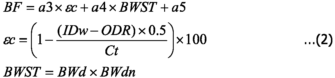 BF: the bead pressing force [N]εc: compressive strain on the inside in the tire radial direction of the bead core 5 [%}IDw: the inner diameter of the bead core 5 [mm]ODR: the diameter of the rim [mm]Ct: a thickness inward in the tire radial direction from the bead core 5 [mm]BWST: a bead wire configurationBWd: a wire diameter of the bead wire [mm]BWdn: a number of the bead wires 8 arranged on the most inside in the tire radial direction [integer]a3: a coefficient for obtaining the pressing force from the compressive straina4: a coefficient for obtaining the pressing force from the bead wire configurationa5: a constant
 - A bead pressing force prediction method, which is a method for predicting a pressing force of a bead portion of a tire equipped with a bead core in the bead portion, and which comprises a step of predicting the pressing force of the bead portion when the tire is fitted onto a rim of a wheel by using the following numeric expression (3):
[ Exp. 3 ] BF: the pressing force of the bead portions 4 [N]BOW: a distance between the center 5c in the tire axial direction of the bead core 5 and the outer surface 4a in the tire axial direction of the bead portion 4 [mm]a6: a coefficienta7: a constant
 - A bead pressing force prediction method, which is a method for predicting a pressing force of a bead portion of a tire equipped with a bead core in the bead portion, and which comprises a step of predicting the pressing force of the bead portion when the tire is fitted onto a rim of a wheel by using the following numeric expression (4):
[ Exp. 4 ] BF: the pressing force of the bead portions 4 [N]BOW: a distance between the center 5c in the tire axial direction of the bead core 5 and the outer surface 4a in the tire axial direction of the bead portion 4 [mm]εc: compressive strain on the inside in the tire radial direction of the bead core 5 [%}IDw: the inner diameter of the bead core 5 [mm]ODR: the diameter of the rim [mm]Ct: a thickness inward in the tire radial direction from the bead core 5 [mm]a8, a9: coefficientsa10: a constant
 - A bead pressing force prediction method, which is a method for predicting a pressing force of a bead portion of a tire equipped with a bead core in the bead portion, the bead core being composed of a bead wire, and which comprises a step of predicting the pressing force of the bead portion when the tire is fitted onto a rim of a wheel by using the following numeric expression (5):
[ Exp. 5 ] BF: the pressing force of the bead portions 4 [N]BOW: a distance between the center 5c in the tire axial direction of the bead core 5 and the outer surface 4a in the tire axial direction of the bead portion 4 [mm]εc: compressive strain on the inside in the tire radial direction of the bead core 5 [%}BWST: a width of the bead core 5 at the innermost position in the radial direction of the tire [mm]IDw: the inner diameter of the bead core 5 [mm]ODR: the diameter of the rim [mm]Ct: a thickness inward in the tire radial direction from the bead core 5 [mm]BWd: a wire diameter of the bead wire [mm]BWdn: a number of the bead wire(s) 8 arranged on the most inside in the tire radial direction [integer]all, a12, a13: coefficientsa14: a constant
 - The bead pressing force prediction method as set forth in claim 1, 2, 4, or 5, wherein
the pressing force of the bead portion is predicted by using an allowable maximum value and allowable minimum value of the diameter of the rim. - The bead pressing force prediction method as set forth in any one of claims 3 to 5, wherein
the distance between the center in the tire axial direction of the bead core and the outer surface in the tire axial direction of the bead portion is predicted by using the following numeric expression (6):
[ Exp. 6 ] BOW: the distance between the center 5c in the tire axial direction of the bead core 5 and the outer surface 4a in the tire axial direction of the bead portion 4 [mm]BG: a thickness of rubber on the outer side in the tire axial direction than the bead core 5 [mm]tch: a thickness of a chafer rubber 9 [mm]Nch: a number of the chafer rubber(s) 9 [integer]tc: a thickness of the carcass ply 6A [mm]ONc: a number of the carcass ply or plies 6A located axially outside the bead core 5 [integer]tj: a thickness of other member [mm]Nj: a number of the other member(s) [integer]BWmax: the maximum width of the bead core 5 [mm]a15: a coefficienta16: a thickness of other rubber [mm]a17: a constant
 - The bead pressing force prediction method as set forth in claim 7, wherein
the maximum width of the bead core is predicted by using the following numeric expression (7):
[ Exp. 7 ] BWmax: the maximum width of the bead core [mm]BWd: the wire diameter of the bead wiresBWdnmax: the maximum number of the bead wires arranged in the axial direction of the tire [integer]a18: a coefficienta19: a constant
 - The bead pressing force prediction method as set forth in claim 1, 2, 4, or 5, wherein
the thickness inward in the tire radial direction from the bead core is predicted by using the following numeric expression (8):
[ Exp. 8 ] Ti: a thickness of an inner liner [mm]Ni: a number of the inner liner(s) located inward in the tire radial direction of the bead core 5 [integer]tc: the thickness of the carcass ply 6A [mm]UNc: a number of the carcass ply or plies 6A located inward in the tire radial direction of the bead core 5 [integer]tch: a thickness of the chafer rubber 9 [mm]Nch: a number of the chafer rubber(s) 9 located inward in the tire radial direction of the bead core 5 [integer]tj: the thickness of the other member [mm]Nj: a number of the other member(s) located inward in the tire radial direction of the bead core 5 [integer]a20: a constanta21: a thickness of other rubber [mm]
 - A tire manufacturing method which is a method of manufacturing a tire comprising a step of configuring a bead portion so that a pressing force of the bead portion predicted by the bead pressing force prediction method as set forth in any one of claims 1 to 9 becomes 1000 to 10000 N.
- A tire, which is a tire of which pressing force of a bead portion predicted by the bead pressing force prediction method as set forth in any one of claims 1 to 9, is 1000 to 10000 N.
Applications Claiming Priority (2)
| Application Number | Priority Date | Filing Date | Title |
|---|---|---|---|
| JP2021026482A JP7574693B2 (en) | 2021-02-22 | 2021-02-22 | Bead tightening force prediction method, tire manufacturing method, and tire |
| PCT/JP2021/038056 WO2022176269A1 (en) | 2021-02-22 | 2021-10-14 | Bead clamping force prediction method, tire manufacturing method, and tire |
Publications (2)
| Publication Number | Publication Date |
|---|---|
| EP4275918A1 true EP4275918A1 (en) | 2023-11-15 |
| EP4275918A4 EP4275918A4 (en) | 2024-10-30 |
Family
ID=82931298
Family Applications (1)
| Application Number | Title | Priority Date | Filing Date |
|---|---|---|---|
| EP21926698.8A Withdrawn EP4275918A4 (en) | 2021-02-22 | 2021-10-14 | BEAD CLAMPING FORCE PREDICTION METHODS, TIRE MANUFACTURING PROCESSES AND TIRE |
Country Status (4)
| Country | Link |
|---|---|
| US (1) | US20240181731A1 (en) |
| EP (1) | EP4275918A4 (en) |
| JP (1) | JP7574693B2 (en) |
| WO (1) | WO2022176269A1 (en) |
Family Cites Families (11)
| Publication number | Priority date | Publication date | Assignee | Title |
|---|---|---|---|---|
| JPS59124415A (en) * | 1982-12-30 | 1984-07-18 | Yokohama Rubber Co Ltd:The | Pneumatic tire |
| JPS63149207A (en) * | 1986-12-12 | 1988-06-22 | Yokohama Rubber Co Ltd:The | Pneumatic tire |
| FR2714179B1 (en) * | 1993-12-22 | 1996-03-01 | Michelin & Cie | Method for correcting variations in radial force between the tire and the ground. |
| JPH0958227A (en) * | 1995-08-28 | 1997-03-04 | Yokohama Rubber Co Ltd:The | Pneumatic tire for passenger car |
| JPH09109624A (en) * | 1995-10-19 | 1997-04-28 | Sumitomo Rubber Ind Ltd | Pneumatic tire |
| JP3124937B2 (en) * | 1996-11-20 | 2001-01-15 | 住友ゴム工業株式会社 | Pneumatic tire |
| JP6763188B2 (en) | 2016-04-18 | 2020-09-30 | 住友ゴム工業株式会社 | Pneumatic tires |
| CN106599413B (en) | 2016-11-30 | 2020-02-07 | 安徽佳通乘用子午线轮胎有限公司 | Tire bead parameter design method based on tire bead pressure |
| CN106739843A (en) | 2017-01-20 | 2017-05-31 | 安徽佳通乘用子午线轮胎有限公司 | Suitable for 5 ° of all steel loads of wedged bottom wheel rim without interior tire |
| JP7110897B2 (en) | 2018-10-11 | 2022-08-02 | 横浜ゴム株式会社 | pneumatic tire |
| JP7459630B2 (en) | 2020-04-10 | 2024-04-02 | 住友ゴム工業株式会社 | Bead tightening force prediction method, tire manufacturing method, and tire |
-
2021
- 2021-02-22 JP JP2021026482A patent/JP7574693B2/en active Active
- 2021-10-14 EP EP21926698.8A patent/EP4275918A4/en not_active Withdrawn
- 2021-10-14 WO PCT/JP2021/038056 patent/WO2022176269A1/en not_active Ceased
- 2021-10-14 US US18/547,319 patent/US20240181731A1/en active Pending
Also Published As
| Publication number | Publication date |
|---|---|
| WO2022176269A1 (en) | 2022-08-25 |
| EP4275918A4 (en) | 2024-10-30 |
| JP7574693B2 (en) | 2024-10-29 |
| US20240181731A1 (en) | 2024-06-06 |
| JP2022128120A (en) | 2022-09-01 |
Similar Documents
| Publication | Publication Date | Title |
|---|---|---|
| EP2910391B1 (en) | Pneumatic tire | |
| EP3482977B1 (en) | Heavy-duty pneumatic tire | |
| EP3156256B1 (en) | Pneumatic tire | |
| US11142027B2 (en) | Pneumatic tire | |
| US20040007305A1 (en) | Pneumatic tire | |
| EP2196327B1 (en) | Pneumatic tire | |
| EP3482976B1 (en) | Heavy-duty pneumatic tire | |
| EP3103658A1 (en) | Pneumatic tire | |
| EP3118027A1 (en) | Heavy-duty pneumatic tire | |
| EP2308694A1 (en) | Pneumatic tire | |
| EP3115231B1 (en) | Pneumatic tire | |
| EP2998128A1 (en) | Pneumatic tire | |
| EP3995322B1 (en) | Tire and belt layer | |
| EP3181375A1 (en) | Pneumatic tire | |
| EP3235664A1 (en) | Pneumatic tire | |
| US20240181731A1 (en) | Bead pressing force prediction method, tire manufacturing method, and tire | |
| EP3936660B1 (en) | Tire | |
| JP7459630B2 (en) | Bead tightening force prediction method, tire manufacturing method, and tire | |
| EP3366496B1 (en) | Run flat tire and method for manufacturing same | |
| EP4059741B1 (en) | Pneumatic tire | |
| EP3943660A1 (en) | Tire | |
| EP4155096A1 (en) | Pneumatic tire | |
| EP3792079A1 (en) | Heavy-duty pneumatic tire | |
| EP3900954B1 (en) | Pneumatic tyre | |
| EP4026709B1 (en) | Pneumatic tire and manufacturing methods therefor |
Legal Events
| Date | Code | Title | Description |
|---|---|---|---|
| STAA | Information on the status of an ep patent application or granted ep patent |
Free format text: STATUS: THE INTERNATIONAL PUBLICATION HAS BEEN MADE |
|
| PUAI | Public reference made under article 153(3) epc to a published international application that has entered the european phase |
Free format text: ORIGINAL CODE: 0009012 |
|
| STAA | Information on the status of an ep patent application or granted ep patent |
Free format text: STATUS: REQUEST FOR EXAMINATION WAS MADE |
|
| 17P | Request for examination filed |
Effective date: 20230810 |
|
| AK | Designated contracting states |
Kind code of ref document: A1 Designated state(s): AL AT BE BG CH CY CZ DE DK EE ES FI FR GB GR HR HU IE IS IT LI LT LU LV MC MK MT NL NO PL PT RO RS SE SI SK SM TR |
|
| P01 | Opt-out of the competence of the unified patent court (upc) registered |
Effective date: 20240327 |
|
| DAV | Request for validation of the european patent (deleted) | ||
| DAX | Request for extension of the european patent (deleted) | ||
| A4 | Supplementary search report drawn up and despatched |
Effective date: 20241001 |
|
| RIC1 | Information provided on ipc code assigned before grant |
Ipc: B60C 15/024 20060101ALI20240925BHEP Ipc: B29D 30/00 20060101ALI20240925BHEP Ipc: B60C 15/04 20060101ALI20240925BHEP Ipc: B29D 30/06 20060101ALI20240925BHEP Ipc: B60C 15/02 20060101ALI20240925BHEP Ipc: B60C 19/00 20060101AFI20240925BHEP |
|
| STAA | Information on the status of an ep patent application or granted ep patent |
Free format text: STATUS: THE APPLICATION IS DEEMED TO BE WITHDRAWN |
|
| 18D | Application deemed to be withdrawn |
Effective date: 20250423 |