EP4275878A2 - Textile covering for electronic device - Google Patents
Textile covering for electronic device Download PDFInfo
- Publication number
- EP4275878A2 EP4275878A2 EP23199982.2A EP23199982A EP4275878A2 EP 4275878 A2 EP4275878 A2 EP 4275878A2 EP 23199982 A EP23199982 A EP 23199982A EP 4275878 A2 EP4275878 A2 EP 4275878A2
- Authority
- EP
- European Patent Office
- Prior art keywords
- seamless tube
- textile covering
- fibers
- electronic device
- textile
- Prior art date
- Legal status (The legal status is an assumption and is not a legal conclusion. Google has not performed a legal analysis and makes no representation as to the accuracy of the status listed.)
- Withdrawn
Links
Images



Classifications
-
- G—PHYSICS
- G06—COMPUTING OR CALCULATING; COUNTING
- G06F—ELECTRIC DIGITAL DATA PROCESSING
- G06F3/00—Input arrangements for transferring data to be processed into a form capable of being handled by the computer; Output arrangements for transferring data from processing unit to output unit, e.g. interface arrangements
- G06F3/01—Input arrangements or combined input and output arrangements for interaction between user and computer
- G06F3/03—Arrangements for converting the position or the displacement of a member into a coded form
- G06F3/033—Pointing devices displaced or positioned by the user, e.g. mice, trackballs, pens or joysticks; Accessories therefor
- G06F3/0354—Pointing devices displaced or positioned by the user, e.g. mice, trackballs, pens or joysticks; Accessories therefor with detection of two-dimensional [2D] relative movements between the device, or an operating part thereof, and a plane or surface, e.g. 2D mice, trackballs, pens or pucks
- G06F3/03545—Pens or stylus
-
- B—PERFORMING OPERATIONS; TRANSPORTING
- B43—WRITING OR DRAWING IMPLEMENTS; BUREAU ACCESSORIES
- B43K—IMPLEMENTS FOR WRITING OR DRAWING
- B43K21/00—Propelling pencils
- B43K21/006—Pencil-barrels
-
- B—PERFORMING OPERATIONS; TRANSPORTING
- B43—WRITING OR DRAWING IMPLEMENTS; BUREAU ACCESSORIES
- B43K—IMPLEMENTS FOR WRITING OR DRAWING
- B43K29/00—Combinations of writing implements with other articles
- B43K29/08—Combinations of writing implements with other articles with measuring, computing or indicating devices
-
- B—PERFORMING OPERATIONS; TRANSPORTING
- B43—WRITING OR DRAWING IMPLEMENTS; BUREAU ACCESSORIES
- B43K—IMPLEMENTS FOR WRITING OR DRAWING
- B43K5/00—Pens with ink reservoirs in holders, e.g. fountain-pens
- B43K5/005—Pen barrels
-
- B—PERFORMING OPERATIONS; TRANSPORTING
- B43—WRITING OR DRAWING IMPLEMENTS; BUREAU ACCESSORIES
- B43K—IMPLEMENTS FOR WRITING OR DRAWING
- B43K7/00—Ball-point pens
- B43K7/005—Pen barrels
-
- B—PERFORMING OPERATIONS; TRANSPORTING
- B43—WRITING OR DRAWING IMPLEMENTS; BUREAU ACCESSORIES
- B43K—IMPLEMENTS FOR WRITING OR DRAWING
- B43K8/00—Pens with writing-points other than nibs or balls
- B43K8/003—Pen barrels
-
- D—TEXTILES; PAPER
- D03—WEAVING
- D03D—WOVEN FABRICS; METHODS OF WEAVING; LOOMS
- D03D1/00—Woven fabrics designed to make specified articles
- D03D1/0088—Fabrics having an electronic function
-
- D—TEXTILES; PAPER
- D03—WEAVING
- D03D—WOVEN FABRICS; METHODS OF WEAVING; LOOMS
- D03D15/00—Woven fabrics characterised by the material, structure or properties of the fibres, filaments, yarns, threads or other warp or weft elements used
- D03D15/50—Woven fabrics characterised by the material, structure or properties of the fibres, filaments, yarns, threads or other warp or weft elements used characterised by the properties of the yarns or threads
- D03D15/567—Shapes or effects upon shrinkage
-
- D—TEXTILES; PAPER
- D03—WEAVING
- D03D—WOVEN FABRICS; METHODS OF WEAVING; LOOMS
- D03D3/00—Woven fabrics characterised by their shape
- D03D3/02—Tubular fabrics
-
- B—PERFORMING OPERATIONS; TRANSPORTING
- B29—WORKING OF PLASTICS; WORKING OF SUBSTANCES IN A PLASTIC STATE IN GENERAL
- B29C—SHAPING OR JOINING OF PLASTICS; SHAPING OF MATERIAL IN A PLASTIC STATE, NOT OTHERWISE PROVIDED FOR; AFTER-TREATMENT OF THE SHAPED PRODUCTS, e.g. REPAIRING
- B29C63/00—Lining or sheathing, i.e. applying preformed layers or sheathings of plastics; Apparatus therefor
- B29C63/0017—Lining or sheathing, i.e. applying preformed layers or sheathings of plastics; Apparatus therefor characterised by the choice of the material
-
- B—PERFORMING OPERATIONS; TRANSPORTING
- B29—WORKING OF PLASTICS; WORKING OF SUBSTANCES IN A PLASTIC STATE IN GENERAL
- B29C—SHAPING OR JOINING OF PLASTICS; SHAPING OF MATERIAL IN A PLASTIC STATE, NOT OTHERWISE PROVIDED FOR; AFTER-TREATMENT OF THE SHAPED PRODUCTS, e.g. REPAIRING
- B29C63/00—Lining or sheathing, i.e. applying preformed layers or sheathings of plastics; Apparatus therefor
- B29C63/24—Lining or sheathing, i.e. applying preformed layers or sheathings of plastics; Apparatus therefor using threads
-
- B—PERFORMING OPERATIONS; TRANSPORTING
- B29—WORKING OF PLASTICS; WORKING OF SUBSTANCES IN A PLASTIC STATE IN GENERAL
- B29C—SHAPING OR JOINING OF PLASTICS; SHAPING OF MATERIAL IN A PLASTIC STATE, NOT OTHERWISE PROVIDED FOR; AFTER-TREATMENT OF THE SHAPED PRODUCTS, e.g. REPAIRING
- B29C63/00—Lining or sheathing, i.e. applying preformed layers or sheathings of plastics; Apparatus therefor
- B29C63/38—Lining or sheathing, i.e. applying preformed layers or sheathings of plastics; Apparatus therefor by liberation of internal stresses
- B29C63/42—Lining or sheathing, i.e. applying preformed layers or sheathings of plastics; Apparatus therefor by liberation of internal stresses using tubular layers or sheathings
-
- B—PERFORMING OPERATIONS; TRANSPORTING
- B29—WORKING OF PLASTICS; WORKING OF SUBSTANCES IN A PLASTIC STATE IN GENERAL
- B29K—INDEXING SCHEME ASSOCIATED WITH SUBCLASSES B29B, B29C OR B29D, RELATING TO MOULDING MATERIALS OR TO MATERIALS FOR MOULDS, REINFORCEMENTS, FILLERS OR PREFORMED PARTS, e.g. INSERTS
- B29K2995/00—Properties of moulding materials, reinforcements, fillers, preformed parts or moulds
- B29K2995/0037—Other properties
- B29K2995/0049—Heat shrinkable
-
- B—PERFORMING OPERATIONS; TRANSPORTING
- B29—WORKING OF PLASTICS; WORKING OF SUBSTANCES IN A PLASTIC STATE IN GENERAL
- B29L—INDEXING SCHEME ASSOCIATED WITH SUBCLASS B29C, RELATING TO PARTICULAR ARTICLES
- B29L2031/00—Other particular articles
- B29L2031/34—Electrical apparatus, e.g. sparking plugs or parts thereof
- B29L2031/3475—Displays, monitors, TV-sets, computer screens
-
- B—PERFORMING OPERATIONS; TRANSPORTING
- B29—WORKING OF PLASTICS; WORKING OF SUBSTANCES IN A PLASTIC STATE IN GENERAL
- B29L—INDEXING SCHEME ASSOCIATED WITH SUBCLASS B29C, RELATING TO PARTICULAR ARTICLES
- B29L2031/00—Other particular articles
- B29L2031/725—Drawing or writing equipment
- B29L2031/7252—Pens, ball-point pens
-
- D—TEXTILES; PAPER
- D10—INDEXING SCHEME ASSOCIATED WITH SUBLASSES OF SECTION D, RELATING TO TEXTILES
- D10B—INDEXING SCHEME ASSOCIATED WITH SUBLASSES OF SECTION D, RELATING TO TEXTILES
- D10B2331/00—Fibres made from polymers obtained otherwise than by reactions only involving carbon-to-carbon unsaturated bonds, e.g. polycondensation products
- D10B2331/04—Fibres made from polymers obtained otherwise than by reactions only involving carbon-to-carbon unsaturated bonds, e.g. polycondensation products polyesters, e.g. polyethylene terephthalate [PET]
-
- D—TEXTILES; PAPER
- D10—INDEXING SCHEME ASSOCIATED WITH SUBLASSES OF SECTION D, RELATING TO TEXTILES
- D10B—INDEXING SCHEME ASSOCIATED WITH SUBLASSES OF SECTION D, RELATING TO TEXTILES
- D10B2401/00—Physical properties
- D10B2401/04—Heat-responsive characteristics
Definitions
- the seamless tube 1 12 takes the form of a cylinder having a substantially uniform diameter along its length.
- suitable textile coverings for an electronic device may have a variety of other forms or structures.
- FIG. 2 shows another example of a textile covering 200 for the pen 104 that comprises a seamless tube 208 including a tapered end that form-fits to a tapered portion of the pen 104.
- Each heat-shrink fiber 320 may be configured to shrink when the seamless tube 308 is heated to a temperature above a threshold temperature, thereby constricting the seamless tube 308 around the barrel 326 of the pen 304.
- the seamless tube 308 may be woven with a slightly larger diameter than the barrel 326 of the pen 304. After sliding and positioning the seamless tube 308 over the barrel 326 of pen 304, the tube may be heated above a threshold temperature, such as approximately 250-260 °C for a polymer yarn, to cause the heat-shrink fibers 320 to constrict and squeeze the tube against the barrel of the pen. In this manner, the seamless tube 308 may accommodate and be securely fitted to a variety of form factors of the underlying device.
- the heat-shrink fibers 320 may enable a seamless tube to accommodate a tapered portion of an electronic device without weaving a tapered end into the seamless tube itself.
- the length of seamless tube 308 of FIG. 3 may be extended to also enclose the tapered end 330 of the pen 304. Once installed over the barrel 326 and tapered end 330, the seamless tube 308 is heated above a threshold temperature that causes the heat-shrink fibers to constrict and form-fit a distal end of the tube to the tapered end.
- a seamless tube of a textile covering may additionally or alternatively include one or more adhesive fibers woven into the tube.
- the one or more adhesive fibers may fuse or adhere the seamless tube to the underlying structure of an electronic device.
- adhesive fibers that may be utilized include nylon and polyester filaments that melt or fuse when heated above a threshold temperature.
- a textile covering 400 may comprise a seamless tube 416 that includes one or more adhesive fibers 412.
- the one or more adhesive fibers may be incorporated in any suitable manner.
- one or more adhesive fibers 412 may be woven into seamless tube 416 in an alternating manner with one or more structural fibers 420.
- the seamless tube 416 may be adhered to a surface of the pen 404 by activating the one or more adhesive fibers 412 when the textile covering 400 is assembled on the pen.
Landscapes
- Engineering & Computer Science (AREA)
- Theoretical Computer Science (AREA)
- Textile Engineering (AREA)
- General Engineering & Computer Science (AREA)
- Human Computer Interaction (AREA)
- Physics & Mathematics (AREA)
- General Physics & Mathematics (AREA)
- Mechanical Engineering (AREA)
- Woven Fabrics (AREA)
- Yarns And Mechanical Finishing Of Yarns Or Ropes (AREA)
- Treatment Of Fiber Materials (AREA)
Abstract
Description
- Some electronic devices may include a covering that provides a visually-appealing appearance and/or a pleasing tactile user interface. Providing a suitable textile covering for an electronic device that embodies these characteristics while also avoiding additional complexity and/or cost in corresponding manufacturing and assembly processes can prove challenging.
- This Summary is provided to introduce a selection of concepts in a simplified form that are further described below in the Detailed Description. This Summary is not intended to identify key features or essential features of the claimed subject matter, nor is it intended to be used to limit the scope of the claimed subject matter. Furthermore, the claimed subject matter is not limited to implementations that solve any or all disadvantages noted in any part of this disclosure.
- Examples are disclosed that relate to textile coverings for electronic devices and methods for manufacturing textile coverings for electronic devices. In one example, a textile covering for an electronic device comprises one or more structural fibers woven into a seamless tube, the seamless tube configured to encircle at least a portion of the electronic device. The textile covering also comprises one or more heat-shrink fibers woven into the seamless tube. The heat-shrink fibers shrink when the seamless tube is heated above a threshold temperature, thereby constricting the seamless tube around the electronic device. Additionally or alternatively, the textile covering may comprise one or more adhesive fibers woven into the seamless tube. The one or more adhesive fibers adhere the textile covering to the electronic device.
- Another example provides a method for manufacturing a textile covering for an electronic device. The method comprises weaving one or more structural fibers into a seamless tube, the seamless tube configured to encircle at least a portion of the electronic device. The method also comprises weaving one or more heat-shrink fibers and/or one or more adhesive fibers into the seamless tube. When the textile covering comprises the one or more heat-shrink fibers, the method comprises heating the seamless tube above a threshold temperature, thereby constricting the seamless tube around the electronic device. When the textile covering comprises the one or more adhesive fibers, the method comprises adhering the textile covering to the electronic device via the adhesive fibers.
-
-
FIG. 1 shows an example of a textile covering for an electronic device according to examples of the present disclosure. -
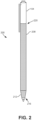
FIG. 2 illustrates another example of a textile covering for an electronic device according to examples of the present disclosure. -
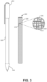
FIG. 3 shows an unassembled view of a textile covering for an electronic device including one or more heat-shrink fibers. -
FIG. 4 shows an unassembled view of a textile covering for an electronic device including one or more adhesive fibers. -
FIG. 5 shows an end view of the textile covering ofFIG. 1 . -
FIG. 6 shows an end view of the textile covering ofFIG. 2 viewed from a tapered end. -
FIG. 7 shows an end view of the textile covering ofFIG. 2 viewed from the non-tapered end. -
FIG. 8 shows an unassembled view of a textile covering for an electronic device including one or more conductive fibers. -
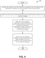
FIG. 9 is a block diagram of an example method for manufacturing a textile covering for an electronic device according to examples of the present disclosure. - Electronic device coverings may provide a device with a visually pleasing and/or personalized appearance, as well as provide a comfortable tactile experience when touched. For example, a textile covering may mask unappealing parts of the electronic device, such as areas that are formed from different materials, openings in the device, or components such as speakers, lights, or sensors,
- In some examples, the textile covering may be configured as a tube that encircles at least a portion of the electronic device. However, tubular textile coverings that include one or more seams may provide a less-than-desirable user experience. For example, a seam may detract from the appearance of the covering and the underlying device. Further, a seam also may hinder or negatively impact the user's tactile interactions with the covering, particularly if it obstructs or overlies a location where the user intends to touch or grip the device.
- Additionally, utilizing a seam may add complexity and/or cost to the covering's assembly and manufacturing processes. For example, in addition to sewing the seam itself, the tube may further require trimming, smoothing, and/or other post-processing procedures to smooth raw edges, treat, or otherwise finish the seam.
- Accordingly, and in one potential advantage of the present disclosure, a textile covering for an electronic device comprises a seamless tube. As described in more detail below, utilizing the seamless tube may simplify the covering's assembly and/or manufacturing, while also contributing to a pleasing visual and tactile user experience. The seamless tubes may include heat-shrink fibers and/or adhesive fibers to improve manufacturabitity and related installation considerations of the covering.
- In some examples, textile coverings of the present disclosure also may provide electronic devices with an intuitive tactile user interface. For example, as described in more detail below, one or more locations on the device may be designated by portions of the textile having distinctive characteristic(s), such as a unique or contrasting tactile feel, a different color, etc. In this manner, users may be guided or naturally drawn to touch or grip the device at such locations.
-
FIG. 1 shows one example of a seamless, tubular textile covering 100 encircling a portion of an electronic device. In the example ofFIG. 1 , the electronic device comprises a hand-held pen 104 (or stylus) configured to provide user input to a computing device. Thepen 104 may also include one or more components, such as buttons, sensors and/or haptic feedback actuators. In some designs, these components could detract from the device's appearance. In such examples, the textile covering 100 may provide the device with a more pleasing and uniform aesthetic, while also augmenting a user's tactile experience with the device. - As shown in
FIG. 1 and described in more detail below, the textile covering 100 comprises one or morestructural fibers 108, such as a thread or other yarn that is woven into aseamless tube 112. In different examples the structural fiber(s) 108 may comprise natural and/or synthetic fibers, such as cotton, silk, wool, nylon, polyester, metallic, composite, and/or other materials. Additionally, and as described in more detail below, the textile covering may include one or more heat shrink fibers and/or one or more adhesive fibers woven into the seamless tube. - The
seamless tube 112 may be formed via any suitable technique, such as by weaving the one or morestructural fibers 108 on a loom. In other examples, knitting, sewing, felting, or other techniques may be utilized. As described below, the yarns may be woven together in a plain weave pattern, in which a single crosswise or weft fiber alternates over and under a single lengthwise or warp fiber. It will be appreciated that the seamless tube may have any other suitable dimensions and textile characteristics that accommodate different types and configurations of electronic devices. For example, the seamless tube may be configured to cover the entire electronic device or only a portion of the device. - In some examples, multiple textile coverings may be created by weaving a single, continuous seamless tube that is then cut to produce coverings of a desired length. Each covering may then be finished using any suitable finishing processes, and treated as a piece part during assembly of the electronic device. Producing the textile covering in this manner may provide operational and cost advantages. However, it will also be appreciated that the textile covering may be produced in any other suitable manner, including producing one at a time.
- In the example of
FIG. 1 and with reference also toFIG. 5 , the seamless tube 1 12 takes the form of a cylinder having a substantially uniform diameter along its length. In other examples, suitable textile coverings for an electronic device may have a variety of other forms or structures. For example,FIG. 2 shows another example of a textile covering 200 for thepen 104 that comprises aseamless tube 208 including a tapered end that form-fits to a tapered portion of thepen 104. - In this example, the
seamless tube 208 comprises atapered end 212 configured to encircle and envelop thetapered portion 216 of thepen 104.FIG. 6 shows an end view of theseamless tube 208 viewed from thetapered end 212.FIG. 7 shows an end view of theseamless tube 208 from thenon-tapered end 220 opposite thetapered end 212. In various examples, the non-tapered portion of theseamless tube 208 may have any suitable circumference, and similarly may taper down to any suitable circumference at the distal end of thetapered end 212. The circumference may taper down over any suitable distance. In different examples, any suitable dimensions and configurations of a seamless tube comprising one or more tapered ends may be utilized to accommodate different configurations of electronic devices. - It will also be appreciated that various characteristics of the textile, such as the EPI and PPI, may be configured in any suitable manner to accommodate the structure of the tapered
seamless tube 208. For example, these characteristics may change in locations where the textile tapers. In this manner, the textile covering 200 may conform to an underlying structure of the electronic device to provide a desired form factor or achieve an intended user experience. - A variety of suitable methods may be used to create such varying forms or structures. In one example of producing a tapered end, the
seamless tube 208 may be woven on a loom that includes one or more adjustable reeds. When the loom is set up, a lengthwise or warp fiber may be threaded through heddles that move the structural fibers into a pattern, then through a "V" reed that sets a density of the fibers. By collapsing the V reed, the fibers may be compacted into a denser structure that reduces the diameter of the seamless tube to produce a tapered end. In this manner, theseamless tube 208 may be woven with a variety of textures and/or shapes. - Additionally and in some examples, different types of fibers may be utilized to alter the shape, texture, and/or other properties of the seamless tube. For example, and with reference again to
FIG. 1 , thestructural fibers 108 ofseamless tube 112 may include two or more different fibers that each comprise a different material. In one example, thestructural fibers 108 may include a nylon air-textured yarn along with a stiffer metallic fiber. In this manner, different structural fibers may utilize materials having different properties and/or other characteristics, such as varying stiffness/softness, elasticity, weight, etc., to provide a variety of tactile user experiences. Additionally and as described in more detail below, other types of fibers including heat-shrinking, adhesive, and/or conductive fibers, may be woven into the seamless tube. - As noted above, incorporating different textures into a textile covering may augment a user's tactile experience with an electronic device. Accordingly, the
seamless tube 112 may comprise a plurality of differently-textured areas to provide a user of thepen 104 with a different tactile experience in each area. For example, the textile covering 100 may provide agrip area 122 that features a softer texture, such as a sateen weave, as compared to other areas of the textile covering. In this manner, the user may have a more comfortable tactile experience and may be more inclined to grip the pen at thegrip area 122. - In some examples, the textile covering may be made thicker in one or more areas to provide the user with visual and tactile cues for where and/or how to grip the device. For example, the grip feature described above may comprise a raised
area 116 that projects outwardly from theseamless tube 112. The structural fibers in the raisedarea 116 may differ from the structural fibers in the rest of theseamless tube 112. For example,cutout view 120 depicts thestructural fibers 108 that comprise most of theseamless tube 112 in the example ofFIG. 1 . In contrast and as schematically shown incutout view 124, the raisedarea 116 of theseamless tube 112 comprises largerstructural fibers 130. As one example, the largerstructural fibers 130 may comprise a thick yarn with a greater diameter and heavier weight than thestructural fibers 108, - Additionally and in some examples, differently-textured areas on the textile covering may be used to guide the user to a location of an underlying component of the
pen 104. Such components may include one or more haptic feedback mechanisms, such as a linear resonant actuator, input buttons, pressure or touch sensors, biometric sensors, etc. Utilizing unique textures at these locations may also enhance tactile feedback when the user interacts with such components, - Such different textures in a textile covering may be provided in a variety of ways. For example, as described above, a loom may be used to weave various textures, forms, and materials into the
seamless tube 112. In other examples, one or more post-processing treatments may be applied to change the texture of theseamless tube 112. Some non-limiting examples of post-processing treatments may include trimming, chemical processing, or applying additional materials onto theseamless tube 112. In other examples, the yarns or other structural fibers may have any other suitable structure configurable to create differently textured areas within theseamless tube 112. - In some examples, different textures may also be provided by incorporating two or more different weave patterns at different locations of the textile covering. For example, one or more of satin, twill, basket weave, and plain weave patterns may utilized at different locations. Accordingly, each weave pattern may provide a different tactile experience when touched.
- For example and with continued reference to
FIG. 1 , theseamless tube 112 may include a roughtextured area 132 in which thestructural fibers 108 may be interwoven with a different weave pattern than in the remainder of theseamless tube 112. As illustrated incutout view 136, in this example thestructural fibers 108 in the roughtextured area 132 may be woven together in a basket weave pattern, wherein two or morestructural fibers 108 are grouped together and woven as one. In contrast, and as shown in thecutout view 120, in the remainder of theseamless tube 112 the samestructural fibers 108 may be woven together in a plain weave pattern. - In this manner, the basket weave pattern may provide a coarser texture in the
rough area 132 as compared to the plain weave pattern utilized in other portions of the cover. It will also be appreciated that in other examples, different weave patterns may be incorporated to provide other effects, such as making the texture smoother. - The
seamless tube 112 may additionally or alternatively include one or more differently-colored areas. Like the differently-textured areas, different colors may indicate various functional areas on thepen 104, such as a location of a button or a sensor. For example, the largestructural fibers 130 in the raisedarea 116 may be given a different color that contrasts with thestructural fibers 108 in the remainder of the covering. This may highlight thegrip area 122 for users. In another example, the roughtextured area 132 may be a different color than the remainder of theseamless tube 112 to indicate the location of a button or sensor. - In some examples, different weave patterns may be used to incorporate different colors into the
seamless tube 112. For example, a jacquard weave may be used to incorporate structural fibers of different colors at different positions on theseamless tube 112 to weave differently-colored areas or different patterns directly into the textile. - It will also be appreciated that such differently-colored areas may be provided in any suitable manner, such as using one or more post-processing treatments. Some non-limiting examples of post-processing color treatments include dying, bleaching, or depositing one or more colored materials on the
seamless tube 112. It will be appreciated that these and other post-processing treatments described herein may be applied at any point during manufacturing or assembly of the textile covering 100 andpen 104, including before and/or after the textile covering 100 is fitted over the device. - As described in more detail below and with reference now to
FIGS. 3-8 , a non-tapered seamless tube and/or a tapered seamless tube as described above may further comprise one or more heat-shrink fibers, one or more adhesive fibers, one or more conductive fibers, an adhesive layer, and/or any combination of these features.FIG. 3 shows an example of an unassembled non-tapered textile covering 300 and corresponding electronic device in the form ofpen 304. Like the examples described above with reference toFIGS. 1 and2 , the textile covering 300 comprises aseamless tube 308 woven with one or morestructural fibers 312. In some examples, to install the textile covering 300 on thepen 304, theseamless tube 308 may be slid over one end of thepen 304. It will also be appreciated that the textile covering 300 may be installed on thepen 304 in any other suitable manner. - To facilitate an easier assembly process, in some examples the
seamless tube 308 may comprise one or more heat-shrink fibers. In these examples, and in one potential advantage of the present disclosure, the heat-shrink fibers may be configured to stretch while being slid over thepen 304, and then constrict around at least a portion of the pen when heated. In the example ofFIG. 3 and as shown incutout 316, one or more heat-shrinkfibers 320 may be woven into theseamless tube 308 in an alternating manner with thestructural fibers 312. In other examples, the one or more heat-shrinkfibers 320 may be incorporated into theseamless tube 308 in any other suitable manner. - The one or more heat-shrink
fibers 320 may comprise any suitable heat-shrink material. Some examples of suitable heat-shrinkfibers 320 include a polyester, lycra, or elastane core surrounded by a natural or synthetic material such as nylon. In this manner, the one or more heat-shrinkfibers 320 may complement the material properties of thestructural fibers 312 by providing theseamless tube 308 with heat-shrink properties. - Each heat-
shrink fiber 320 may be configured to shrink when theseamless tube 308 is heated to a temperature above a threshold temperature, thereby constricting theseamless tube 308 around thebarrel 326 of thepen 304. In some examples, to facilitate easier assembly, theseamless tube 308 may be woven with a slightly larger diameter than thebarrel 326 of thepen 304. After sliding and positioning theseamless tube 308 over thebarrel 326 ofpen 304, the tube may be heated above a threshold temperature, such as approximately 250-260 °C for a polymer yarn, to cause the heat-shrinkfibers 320 to constrict and squeeze the tube against the barrel of the pen. In this manner, theseamless tube 308 may accommodate and be securely fitted to a variety of form factors of the underlying device. - For example, the heat-shrink
fibers 320 may enable a seamless tube to accommodate a tapered portion of an electronic device without weaving a tapered end into the seamless tube itself. In one example, the length ofseamless tube 308 ofFIG. 3 may be extended to also enclose thetapered end 330 of thepen 304. Once installed over thebarrel 326 andtapered end 330, theseamless tube 308 is heated above a threshold temperature that causes the heat-shrink fibers to constrict and form-fit a distal end of the tube to the tapered end. - In other examples, a seamless tube that includes a woven tapered end, such as the
seamless tube 208 ofFIG. 2 , may incorporate heat-shrink fibers within the woven tapered end. In this manner, the heat-shrink fibers may enable the tapered end to more securely seat around the corresponding underlying tapered structure. In some examples, the heat-shrink fibers may enable the tapered end of a seamless tube to shrink to a narrower diameter than may be woven on a loom. - In some examples, a seamless tube of a textile covering may additionally or alternatively include one or more adhesive fibers woven into the tube. In these examples, the one or more adhesive fibers may fuse or adhere the seamless tube to the underlying structure of an electronic device. Examples of adhesive fibers that may be utilized include nylon and polyester filaments that melt or fuse when heated above a threshold temperature.
- In one example and with reference now to
FIG. 4 , a textile covering 400 may comprise aseamless tube 416 that includes one or moreadhesive fibers 412. The one or more adhesive fibers may be incorporated in any suitable manner. For example, and as shown incutout 408, one or moreadhesive fibers 412 may be woven intoseamless tube 416 in an alternating manner with one or morestructural fibers 420. In this manner, theseamless tube 416 may be adhered to a surface of thepen 404 by activating the one or moreadhesive fibers 412 when the textile covering 400 is assembled on the pen. - In other examples, a textile covering may be adhered to an electronic device via a layer or film of adhesive material deposited on an inner surface of the covering. For example,
FIG. 5 shows an end view of the textile covering 100 ofFIG. 1 . As shown inFIG. 5 , the textile covering 100 may include an inneradhesive layer 156 on the inner surface of theseamless tube 112, with the adhesive layer configured to adhere the tube to thepen 104. Theadhesive layer 156 may comprise any suitable adhesive material, such as a polyurethane or thermoplasti c heat-activated film, a pressure-sensitive coating, or other suitable adhesive. In this example, theadhesive layer 156 is positioned adjacent to the barrel ofpen 104 when theseamless tube 112 is slid over the pen. In other examples, theadhesive layer 156 may initially be formed on an outer surface of theseamless tube 112, which is then inverted before or during assembly of thepen 104. In different examples, the adhesive layer may cover substantially all of the inner surface of theseamless tube 112, or one or more portions of the inner surface. -
FIGS. 6 and 7 illustrate similar end views of the textile covering 200 ofFIG. 2 .FIG. 6 shows an end view of theseamless tube 208 viewed from thetapered end 212.FIG. 7 shows an end view of the textile covering 200 from the oppositenon-tapered end 220. As shown inFIGS. 6 and 7 , the textile covering 200 may also comprise an inneradhesive layer 226, which may follow the shape of the inner surface ofseamless tube 208 into thetapered end 212. - In some examples, one or more of the textile coverings described herein may be configured to be interchangeable with other coverings. In this manner, and with reference to the example of
FIG. 1 , thepen 104 may accommodate one or more different textiles coverings in addition to the textile covering 100. In this manner, different textile coverings may be selected to accommodate different ergonomic preferences and/or accessibility requirements of various users. For example, different features of the textile covering 100 may be particularly configured for users living with arthritis or other dexterity-related conditions, for left-handed or right-handed users, or others. The textile covering 100 may also be interchangeable for cosmetic purposes, such as to enable users to customize the device's color. - In some examples, a seamless tube of a textile covering may additionally or alternatively include one or more conductive fibers woven into the tube that may complement functionality of an underlying electronic device. For example, sensing and/or output functionali ty of a device may be provided or enhanced by incorporating one or more conductive fibers into a textile covering.
- With reference now to
FIG. 8 , a textile covering 800 may include electronic functionality that complements apen 804. As schematically illustrated incutout 808, one or moreconductive fibers 812 may be sewn intoseamless tube 816 over one or morestructural fibers 820. In other examples, theconductive fibers 812 may be woven or incorporated into theseamless tube 816 in any other suitable manner. For example, theconductive fibers 812 may be woven into theseamless tube 816 along with thestructural fibers 820 in a manner similar to the heat-shrinkfibers 320 in the example ofFIG. 3 described above, or similar to theadhesive fibers 412 in the example ofFIG. 4 . - The one or more
conductive fibers 812 may comprise any suitable material or structure. In some examples, each of theconductive fibers 812 may comprise an intrinsically conductive wire covered by a textile material, such as a silver or copper core covered with nylon or polyester. For example, a conductive yarn may be formed via a pull through yarn process. In this manner, robust, wrapped wires may be produced that may be woven into theseamless tube 816. - In another example, each of the one or more
conductive fibers 812 may comprise a nonconductive material, such as a polymer, monofilament, or staple filament, that is treated with a conductor, such as copper or silver, and formed into a yarn. In other examples, eachconductive fiber 812 may comprise a conductive yarn coated with an enamel dielectric coating. In this manner, the dielectric coating may prevent theconductive fibers 812 from short-circuiting. - The one or more
conductive fibers 812 may provide the textile covering 800 with touch-sensing or other electronic capability. For example, the one or moreconductive fibers 812 may comprise a resistive or capacitive touch sensor, pressure sensor, and/or proximity sensor, an antenna, an inductive coil for wireless charging, an inductive sensor, or any other suitable electronic component. Theconductive fibers 812 may additionally or alternatively facilitate connections with one or more output components and/or indicators, such as standalone lights or LED arrays, which in some examples may be printed on flexible circuit boards. - Utilizing conductive fibers in this manner may provide the
pen 804 with a wide range of functionality. For example, the one or moreconductive fibers 812 may comprise a touch sensor integrated into the textile covering 800 and configured to detect how a user is holding thepen 804. In some examples, the user's grip on thepen 804 may be used to predict how the user's hand may occlude a display of a tablet computing device, which may respond by rearranging how user interface elements are displayed. Similar inputs may also help the tablet computing device filter out noise from the user's hand contacting a touch-screen display, or rearrange the user interface to accommodate preferences of left- or right-handed users. In yet another example, the one or moreconductive fibers 812 may also provide biometric sensing capabilities, which may be used to help a computing device identify the user. - Accordingly, by weaving the one or more
conductive fibers 812 into theseamless tube 816, sensing functionality may be provided by the textile covering 800. In some examples, the one or moreconductive fibers 812 may form a continuous sensor around the entirety of theseamless tube 816. In other examples, electronic functionality may be provided by depositing one or more conductive traces on the textile material. For example, conductive traces may be printed on an inside or outside surface of the textile by processes such as silk screening or ink jet printing. - It will be appreciated that textile coverings of the present disclosure may or may not include electronic functionality and/or conductive components. For example, a textile covering configured to cover an electronic device for cosmetic and/or tactile purposes may not include conductive properties.
- With reference now to
FIG. 9 , a flow diagram is provided depicting anexample method 900 for manufacturing a textile covering for an electronic device. The following description ofmethod 900 is provided with reference to the materials and components described herein and shown inFIGS. 1-8 . It will be appreciated thatmethod 900 also may be performed in other contexts using other suitable materials and components, - At 904, the
method 900 includes weaving one or more structural fibers into a seamless tube that is configured to encircle at least a portion of the electronic device. At 908, themethod 900 includes weaving one or more heat-shrink fibers and/or one or more adhesive fibers into the seamless tube. At 912, themethod 900 includes, when the textile covering comprises the one or more heat-shrink fibers, heating the seamless tube above a threshold temperature to constrict the seamless tube around the electronic device. At 916, themethod 900 includes, when the textile covering comprises the one or more adhesive fibers, adhering the textile covering to the electronic device via the adhesive fibers. - The following paragraphs provide additional support for the claims of the subject application. One aspect provides a textile covering for an electronic device, the textile covering comprising: one or more structural fibers woven into a seamless tube, the seamless tube configured to encircle at least a portion of the electronic device; and one or more heat-shrink fibers woven into the seamless tube, wherein the heat-shrink fibers shrink when the seamless tube is heated above a threshold temperature, thereby constricting the seamless tube around the electronic device. The textile covering may additionally or alternatively include, wherein the seamless tube further comprises a tapered end. The textile covering may additionally or alternatively include, wherein the one or more heat-shrink fibers comprise one or more polyester or elastane fibers. The textile covering may additionally or alternatively include, an adhesive layer configured to adhere the textile covering to the electronic device. The textile covering may additionally or alternatively include, one or more adhesive fibers woven into the seamless tube, wherein the one or more adhesive fibers adhere the textile covering to the electronic device. The textile covering may additionally or alternatively include, wherein the one or more structural fibers comprise two or more different structural fibers that each comprise a different material. The textile covering may additionally or alternatively include, wherein the seamless tube further comprises a plurality of differently-textured areas. The textile covering may additionally or alternatively include, wherein each of the differently-textured areas comprises a differently-sized structural fiber. The textile covering may additionally or alternatively include, wherein each of the differently-textured areas comprises a different weave pattern. The textile covering may additionally or alternatively include, wherein one or more of the plurality of differently-textured areas indicate an underlying component of the electronic device. The textile covering may additionally or alternatively include, one or more conductive fibers woven into the seamless tube. The textile covering may additionally or alternatively include, wherein the one or more conductive fibers provide inputs to the electronic device. The textile covering may additionally or alternatively include, wherein the electronic device comprises a hand-held pen configured to provide user input to a computing device.
- Another aspect provides a textile covering for an electronic device, the textile covering comprising: one or more structural fibers woven into a seamless tube, the seamless tube configured to encircle at least a portion of the electronic device; and one or more adhesive fibers woven into the seamless tube, wherein the one or more adhesive fibers adhere the textile covering to the electronic device. The textile covering may additionally or alternatively include, wherein the seamless tube further comprises a tapered end. The textile covering may additionally or alternatively include, wherein the one or more structural fibers comprise two or more different structural fibers that each comprise a different material. The textile covering may additionally or alternatively include, wherein the seamless tube further comprises a plurality of differently-textured areas. The textile covering may additionally or alternatively include, wherein each of the differently-textured areas comprises a differently-sized structural fiber. The textile covering may additionally or alternatively include, wherein each of the differently-textured areas comprises a different weave pattern. The textile covering may additionally or alternatively include, wherein one or more of the plurality of differently-textured areas indicate an underlying component of the electronic device. The textile covering may additionally or alternatively include, one or more conductive fibers woven into the seamless tube. The textile covering may additionally or alternatively include, wherein the one or more conductive fibers provide inputs to the electronic device. The textile covering may additionally or alternatively include, wherein the electronic device comprises a hand-held pen configured to provide user input to a computing device.
- Another aspect provides a method for manufacturing a textile covering for an electronic device, the method comprising: weaving one or more structural fibers into a seamless tube, the seamless tube configured to encircle at least a portion of the electronic device, weaving one or more heat-shrink fibers and/or one or more adhesive fibers into the seamless tube; when the textile covering comprises the one or more heat-shrink fibers, heating the seamless tube above a threshold temperature, thereby constricting the seamless tube around the electronic device; and when the textile covering comprises the one or more adhesive fibers, adhering the textile covering to the electronic device via the adhesive fibers.
- It will be understood that the configurations and/or approaches described herein are exemplary in nature, and that these specific embodiments or examples are not to be considered in a limiting sense, because numerous variations are possible. The specific routines or methods described herein may represent one or more of any number of strategies. As such, various acts illustrated and/or described may be performed in the sequence illustrated and/or described, in other sequences, in parallel, or omitted. Likewise, the order of the above-described processes may be changed.
- The subject matter of the present disclosure includes all novel and non-obvious combinations and sub-combinations of the various processes, systems and configurations, and other features, functions, acts, and/or properties disclosed herein, as well as any and all equivalents thereof.
- The present teaching may also extend to one of more of the following numbered clauses:
- 1. A textile covering for an electronic device, the textile covering comprising:
- one or more structural fibers woven into a seamless tube, the seamless tube configured to encircle at least a portion of the electronic device; and
- one or more heat-shrink fibers woven into the seamless tube,
- wherein the heat-shrink fibers shrink when the seamless tube is heated above a threshold temperature, thereby constricting the seamless tube around the electronic device.
- 2. The textile covering of clause 1, wherein the seamless tube further comprises a tapered end.
- 3. The textile covering of clause 1, further comprising an adhesive layer configured to adhere the textile covering to the electronic device.
- 4. The textile covering of clause 1, further comprising one or more adhesive fibers woven into the seamless tube, wherein the one or more adhesive fibers adhere the textile covering to the electronic device.
- 5. The textile covering of clause 1, wherein the one or more structural fibers comprise two or more different structural fibers that each comprise a different material.
- 6. The textile covering of clause 1, wherein the seamless tube further comprises a plurality of differently-textured areas.
- 7. The textile covering of clause 6, wherein one or more of the plurality of differently-textured areas indicate an underlying component of the electronic device.
- 8. The textile covering of clause 1, further comprising one or more conductive fibers woven into the seamless tube.
- 9. The textile covering of clause 8, wherein the one or more conductive fibers provide inputs to the electronic device.
- 10. A textile covering for an electronic device, the textile covering comprising:
- one or more structural fibers woven into a seamless tube, the seamless tube configured to encircle at least a portion of the electronic device; and
- one or more adhesive fibers woven into the seamless tube, wherein the one or more adhesive fibers adhere the textile covering to the electronic device.
- 11. The textile covering of clause 10, wherein the seamless tube further comprises a tapered end.
- 12. The textile covering of clause 10, wherein the one or more structural fibers comprise two or more different structural fibers that each comprise a different material.
- 13. The textile covering of clause 10, wherein the seamless tube further comprises a plurality of differently-textured areas.
- 14. The textile covering of
clause 13, wherein one or more of the plurality of differently-textured areas indicate an underlying component of the electronic device. - 15. The textile covering of clause 10, further comprising one or more conductive fibers woven into the seamless tube.
Claims (15)
- A textile covering for an electronic device, the textile covering comprising:one or more structural fibers woven into a seamless tube, the seamless tube configured to encircle at least a portion of the electronic device;one or more conductive fibers woven into the seamless tube; andone or more heat-shrink fibers woven into the seamless tube,wherein the heat-shrink fibers shrink when the seamless tube is heated above a threshold temperature, thereby constricting the seamless tube around the electronic device.
- The textile covering of claim 1, wherein the seamless tube further comprises a tapered end.
- The textile covering of claim 1, further comprising an adhesive layer configured to adhere the textile covering to the electronic device.
- The textile covering of claim 1, further comprising one or more adhesive fibers woven into the seamless tube, wherein the one or more adhesive fibers adhere the textile covering to the electronic device.
- The textile covering of claim 1, wherein the one or more structural fibers comprise two or more different structural fibers that each comprise a different material.
- The textile covering of claim 1, wherein the seamless tube further comprises a plurality of differently-textured areas.
- The textile covering of claim 6, wherein one or more of the plurality of differently-textured areas are configured for indicating an underlying component of the electronic device.
- The textile covering of claim 1, wherein the one or more conductive fibers provide inputs to the electronic device; optionally the one or more conductive fibers form a continuous sensor around the seamless tube.
- The textile covering of claim 1, further configured to encircle a hand-held pen configured to provide user input to a computing device.
- A textile covering for an electronic device, the textile covering comprising:one or more structural fibers woven into a seamless tube, the seamless tube configured to encircle at least a portion of the electronic device;one or more conductive fibers woven into the seamless tube; andone or more adhesive fibers woven into the seamless tube, wherein the one or more adhesive fibers adhere the textile covering to the electronic device.
- The textile covering of claim 10, wherein the seamless tube further comprises a tapered end.
- The textile covering of claim 10, wherein the one or more structural fibers comprise two or more different structural fibers that each comprise a different material.
- The textile covering of claim 10, wherein the seamless tube further comprises a plurality of differently-textured areas; optionally wherein one or more of the plurality of differently-textured areas are configured for indicating an underlying component of the electronic device.
- The textile covering of claim 10, wherein the one or more conductive fibers provide inputs to the electronic device; optionally the one or more conductive fibers form a continuous sensor around the seamless tube.
- The textile covering of claim 10, further configured to encircle a hand-held pen configured to provide user input to a computing device.
Applications Claiming Priority (3)
| Application Number | Priority Date | Filing Date | Title |
|---|---|---|---|
| US16/285,033 US20200270778A1 (en) | 2019-02-25 | 2019-02-25 | Textile covering for electronic device |
| EP20710377.1A EP3931673B1 (en) | 2019-02-25 | 2020-02-10 | Textile covering for electronic device |
| PCT/US2020/017402 WO2020176231A1 (en) | 2019-02-25 | 2020-02-10 | Textile covering for electronic device |
Related Parent Applications (2)
| Application Number | Title | Priority Date | Filing Date |
|---|---|---|---|
| EP20710377.1A Division-Into EP3931673B1 (en) | 2019-02-25 | 2020-02-10 | Textile covering for electronic device |
| EP20710377.1A Division EP3931673B1 (en) | 2019-02-25 | 2020-02-10 | Textile covering for electronic device |
Publications (2)
| Publication Number | Publication Date |
|---|---|
| EP4275878A2 true EP4275878A2 (en) | 2023-11-15 |
| EP4275878A3 EP4275878A3 (en) | 2024-02-21 |
Family
ID=69780330
Family Applications (2)
| Application Number | Title | Priority Date | Filing Date |
|---|---|---|---|
| EP20710377.1A Active EP3931673B1 (en) | 2019-02-25 | 2020-02-10 | Textile covering for electronic device |
| EP23199982.2A Withdrawn EP4275878A3 (en) | 2019-02-25 | 2020-02-10 | Textile covering for electronic device |
Family Applications Before (1)
| Application Number | Title | Priority Date | Filing Date |
|---|---|---|---|
| EP20710377.1A Active EP3931673B1 (en) | 2019-02-25 | 2020-02-10 | Textile covering for electronic device |
Country Status (3)
| Country | Link |
|---|---|
| US (1) | US20200270778A1 (en) |
| EP (2) | EP3931673B1 (en) |
| WO (1) | WO2020176231A1 (en) |
Families Citing this family (5)
| Publication number | Priority date | Publication date | Assignee | Title |
|---|---|---|---|---|
| US11507206B2 (en) | 2019-05-13 | 2022-11-22 | Microsoft Technology Licensing, Llc | Force-sensing input device |
| US10942585B2 (en) | 2019-07-22 | 2021-03-09 | Zspace, Inc. | Trackability enhancement of a passive stylus |
| USD936142S1 (en) * | 2021-03-12 | 2021-11-16 | Jianfei Lan | Pen |
| US12018411B2 (en) | 2021-05-10 | 2024-06-25 | Under Armour, Inc. | Method of forming an upper for an article of footwear |
| US12492492B2 (en) | 2021-05-21 | 2025-12-09 | Microsoft Technology Licensing, Llc | Single repeat woven panel |
Family Cites Families (10)
| Publication number | Priority date | Publication date | Assignee | Title |
|---|---|---|---|---|
| US2970937A (en) * | 1958-08-15 | 1961-02-07 | Belden Mfg Co | Method of forming insulated wire |
| GB2075991B (en) * | 1980-05-13 | 1983-12-07 | Raychem Sa Nv | Hot melt adhesive compositions containing polyamides |
| GB9711160D0 (en) * | 1997-05-30 | 1997-07-23 | Raychem Ltd | Cutting heat-shrinkable fabrics |
| US6962735B2 (en) * | 2001-08-31 | 2005-11-08 | Milliken & Company | Textile printing substrate |
| CN101642992A (en) * | 2009-09-11 | 2010-02-10 | 深圳市宏商材料科技股份有限公司 | Use of heat-shrinkage mark sleeve, and writing pen and refill sleeved with mark sleeve |
| JP6161498B2 (en) * | 2012-11-06 | 2017-07-12 | 東和化成株式会社 | Input pen and method for manufacturing the same |
| TWM454570U (en) * | 2012-12-10 | 2013-06-01 | zhen-hua Wu | Structure improvement of touch control pen |
| US9307685B2 (en) * | 2014-07-16 | 2016-04-05 | Federal-Mogul Powertrain, Inc. | Protective sleeve with bonded wire filaments and methods of construction thereof |
| US10082913B2 (en) * | 2015-05-10 | 2018-09-25 | Microsoft Technology Licensing, Llc | Embroidered sensor assembly |
| TWM545570U (en) * | 2017-03-21 | 2017-07-21 | meng-chun Wang | Joint angle adjustment mechanism |
-
2019
- 2019-02-25 US US16/285,033 patent/US20200270778A1/en not_active Abandoned
-
2020
- 2020-02-10 EP EP20710377.1A patent/EP3931673B1/en active Active
- 2020-02-10 EP EP23199982.2A patent/EP4275878A3/en not_active Withdrawn
- 2020-02-10 WO PCT/US2020/017402 patent/WO2020176231A1/en not_active Ceased
Also Published As
| Publication number | Publication date |
|---|---|
| EP3931673B1 (en) | 2023-11-01 |
| US20200270778A1 (en) | 2020-08-27 |
| EP4275878A3 (en) | 2024-02-21 |
| EP3931673A1 (en) | 2022-01-05 |
| WO2020176231A1 (en) | 2020-09-03 |
Similar Documents
| Publication | Publication Date | Title |
|---|---|---|
| EP4275878A2 (en) | Textile covering for electronic device | |
| RU2377347C2 (en) | Method for making of knitted glove and knitted glove | |
| CA2770333C (en) | Glove with conductive fingertips | |
| US10876229B2 (en) | Conductive yarn structure for interactive textiles | |
| CN104270973B (en) | Seamless ridge reinforced glove | |
| US7908891B2 (en) | Knitted glove | |
| JP6288623B2 (en) | Textile products and metal fibers | |
| US20190352808A1 (en) | Electronically functional yarn and textile | |
| WO2013055759A1 (en) | Process for making knit embroidered conductive gloves | |
| EP1797228A1 (en) | Knitted glove with controlled stitch stretch capability | |
| WO2017111687A1 (en) | Electrically conductive yarn and a product including the yarn | |
| Roh | Conductive Yarn Embroidered Circuits for System on | |
| CN205467702U (en) | Single face chamois leather matte material | |
| US20140165658A1 (en) | Process for making knit embroidered conductive gloves | |
| KR20040104682A (en) | Switch | |
| JP6910627B2 (en) | Sewing thread for sewing machines used in electric circuits | |
| KR20060029641A (en) | Touch sensing interface | |
| Ahteck | Electronic Embedded Lace: A Sampler of Functional Interactive Tatting Techniques and Circuits | |
| EP4611579B1 (en) | Knitted grip strengthening glove | |
| CN201976795U (en) | Glove structure for capacitive touch screen operation | |
| CN219731197U (en) | Twisted yarn-dyed imitation fashion fabric | |
| KR20190072488A (en) | Fiber-based capacitive pressure sensor | |
| Chen | The design of tactile knitted e-textiles for interactive applications | |
| KR101944742B1 (en) | Surface finishing material for an automobile interior material containing conductive embroidery fabric and automobile interior material using the same | |
| AU2012100306A4 (en) | Glove with conductive fingertips |
Legal Events
| Date | Code | Title | Description |
|---|---|---|---|
| PUAI | Public reference made under article 153(3) epc to a published international application that has entered the european phase |
Free format text: ORIGINAL CODE: 0009012 |
|
| STAA | Information on the status of an ep patent application or granted ep patent |
Free format text: STATUS: THE APPLICATION HAS BEEN PUBLISHED |
|
| AC | Divisional application: reference to earlier application |
Ref document number: 3931673 Country of ref document: EP Kind code of ref document: P |
|
| AK | Designated contracting states |
Kind code of ref document: A2 Designated state(s): AL AT BE BG CH CY CZ DE DK EE ES FI FR GB GR HR HU IE IS IT LI LT LU LV MC MK MT NL NO PL PT RO RS SE SI SK SM TR |
|
| REG | Reference to a national code |
Ref country code: DE Ref legal event code: R079 Free format text: PREVIOUS MAIN CLASS: B29L0031340000 Ipc: G06F0003035400 |
|
| PUAL | Search report despatched |
Free format text: ORIGINAL CODE: 0009013 |
|
| AK | Designated contracting states |
Kind code of ref document: A3 Designated state(s): AL AT BE BG CH CY CZ DE DK EE ES FI FR GB GR HR HU IE IS IT LI LT LU LV MC MK MT NL NO PL PT RO RS SE SI SK SM TR |
|
| RIC1 | Information provided on ipc code assigned before grant |
Ipc: B29L 31/00 20060101ALI20240112BHEP Ipc: B29L 31/34 20060101ALI20240112BHEP Ipc: B43K 29/08 20060101ALI20240112BHEP Ipc: B43K 21/00 20060101ALI20240112BHEP Ipc: D03D 1/00 20060101ALI20240112BHEP Ipc: B43K 8/00 20060101ALI20240112BHEP Ipc: B43K 7/00 20060101ALI20240112BHEP Ipc: B43K 5/00 20060101ALI20240112BHEP Ipc: B29C 63/24 20060101ALI20240112BHEP Ipc: B29C 63/00 20060101ALI20240112BHEP Ipc: D03D 3/02 20060101ALI20240112BHEP Ipc: B43K 23/00 20060101ALI20240112BHEP Ipc: B29C 63/42 20060101ALI20240112BHEP Ipc: G06F 3/0354 20130101AFI20240112BHEP |
|
| STAA | Information on the status of an ep patent application or granted ep patent |
Free format text: STATUS: REQUEST FOR EXAMINATION WAS MADE |
|
| 17P | Request for examination filed |
Effective date: 20240819 |
|
| RBV | Designated contracting states (corrected) |
Designated state(s): AL AT BE BG CH CY CZ DE DK EE ES FI FR GB GR HR HU IE IS IT LI LT LU LV MC MK MT NL NO PL PT RO RS SE SI SK SM TR |
|
| STAA | Information on the status of an ep patent application or granted ep patent |
Free format text: STATUS: THE APPLICATION HAS BEEN WITHDRAWN |
|
| 18W | Application withdrawn |
Effective date: 20241119 |