EP4275872A1 - Rotating manifolds and associated systems and methods for vacuum bagging large composite structures - Google Patents
Rotating manifolds and associated systems and methods for vacuum bagging large composite structures Download PDFInfo
- Publication number
- EP4275872A1 EP4275872A1 EP23153964.4A EP23153964A EP4275872A1 EP 4275872 A1 EP4275872 A1 EP 4275872A1 EP 23153964 A EP23153964 A EP 23153964A EP 4275872 A1 EP4275872 A1 EP 4275872A1
- Authority
- EP
- European Patent Office
- Prior art keywords
- vacuum
- hub
- conduits
- compressed air
- rotating manifold
- Prior art date
- Legal status (The legal status is an assumption and is not a legal conclusion. Google has not performed a legal analysis and makes no representation as to the accuracy of the status listed.)
- Granted
Links
Images






Classifications
-
- B—PERFORMING OPERATIONS; TRANSPORTING
- B29—WORKING OF PLASTICS; WORKING OF SUBSTANCES IN A PLASTIC STATE IN GENERAL
- B29C—SHAPING OR JOINING OF PLASTICS; SHAPING OF MATERIAL IN A PLASTIC STATE, NOT OTHERWISE PROVIDED FOR; AFTER-TREATMENT OF THE SHAPED PRODUCTS, e.g. REPAIRING
- B29C70/00—Shaping composites, i.e. plastics material comprising reinforcements, fillers or preformed parts, e.g. inserts
- B29C70/04—Shaping composites, i.e. plastics material comprising reinforcements, fillers or preformed parts, e.g. inserts comprising reinforcements only, e.g. self-reinforcing plastics
- B29C70/28—Shaping operations therefor
- B29C70/30—Shaping by lay-up, i.e. applying fibres, tape or broadsheet on a mould, former or core; Shaping by spray-up, i.e. spraying of fibres on a mould, former or core
- B29C70/34—Shaping by lay-up, i.e. applying fibres, tape or broadsheet on a mould, former or core; Shaping by spray-up, i.e. spraying of fibres on a mould, former or core and shaping or impregnating by compression, i.e. combined with compressing after the lay-up operation
- B29C70/342—Shaping by lay-up, i.e. applying fibres, tape or broadsheet on a mould, former or core; Shaping by spray-up, i.e. spraying of fibres on a mould, former or core and shaping or impregnating by compression, i.e. combined with compressing after the lay-up operation using isostatic pressure
-
- B—PERFORMING OPERATIONS; TRANSPORTING
- B29—WORKING OF PLASTICS; WORKING OF SUBSTANCES IN A PLASTIC STATE IN GENERAL
- B29C—SHAPING OR JOINING OF PLASTICS; SHAPING OF MATERIAL IN A PLASTIC STATE, NOT OTHERWISE PROVIDED FOR; AFTER-TREATMENT OF THE SHAPED PRODUCTS, e.g. REPAIRING
- B29C70/00—Shaping composites, i.e. plastics material comprising reinforcements, fillers or preformed parts, e.g. inserts
- B29C70/04—Shaping composites, i.e. plastics material comprising reinforcements, fillers or preformed parts, e.g. inserts comprising reinforcements only, e.g. self-reinforcing plastics
- B29C70/28—Shaping operations therefor
- B29C70/40—Shaping or impregnating by compression not applied
- B29C70/42—Shaping or impregnating by compression not applied for producing articles of definite length, i.e. discrete articles
- B29C70/44—Shaping or impregnating by compression not applied for producing articles of definite length, i.e. discrete articles using isostatic pressure, e.g. pressure difference-moulding, vacuum bag-moulding, autoclave-moulding or expanding rubber-moulding
- B29C70/446—Moulding structures having an axis of symmetry or at least one channel, e.g. tubular structures, frames
-
- B—PERFORMING OPERATIONS; TRANSPORTING
- B29—WORKING OF PLASTICS; WORKING OF SUBSTANCES IN A PLASTIC STATE IN GENERAL
- B29C—SHAPING OR JOINING OF PLASTICS; SHAPING OF MATERIAL IN A PLASTIC STATE, NOT OTHERWISE PROVIDED FOR; AFTER-TREATMENT OF THE SHAPED PRODUCTS, e.g. REPAIRING
- B29C70/00—Shaping composites, i.e. plastics material comprising reinforcements, fillers or preformed parts, e.g. inserts
- B29C70/04—Shaping composites, i.e. plastics material comprising reinforcements, fillers or preformed parts, e.g. inserts comprising reinforcements only, e.g. self-reinforcing plastics
- B29C70/28—Shaping operations therefor
- B29C70/30—Shaping by lay-up, i.e. applying fibres, tape or broadsheet on a mould, former or core; Shaping by spray-up, i.e. spraying of fibres on a mould, former or core
- B29C70/32—Shaping by lay-up, i.e. applying fibres, tape or broadsheet on a mould, former or core; Shaping by spray-up, i.e. spraying of fibres on a mould, former or core on a rotating mould, former or core
-
- B—PERFORMING OPERATIONS; TRANSPORTING
- B29—WORKING OF PLASTICS; WORKING OF SUBSTANCES IN A PLASTIC STATE IN GENERAL
- B29C—SHAPING OR JOINING OF PLASTICS; SHAPING OF MATERIAL IN A PLASTIC STATE, NOT OTHERWISE PROVIDED FOR; AFTER-TREATMENT OF THE SHAPED PRODUCTS, e.g. REPAIRING
- B29C70/00—Shaping composites, i.e. plastics material comprising reinforcements, fillers or preformed parts, e.g. inserts
- B29C70/04—Shaping composites, i.e. plastics material comprising reinforcements, fillers or preformed parts, e.g. inserts comprising reinforcements only, e.g. self-reinforcing plastics
- B29C70/28—Shaping operations therefor
- B29C70/54—Component parts, details or accessories; Auxiliary operations, e.g. feeding or storage of prepregs or SMC after impregnation or during ageing
-
- B—PERFORMING OPERATIONS; TRANSPORTING
- B29—WORKING OF PLASTICS; WORKING OF SUBSTANCES IN A PLASTIC STATE IN GENERAL
- B29C—SHAPING OR JOINING OF PLASTICS; SHAPING OF MATERIAL IN A PLASTIC STATE, NOT OTHERWISE PROVIDED FOR; AFTER-TREATMENT OF THE SHAPED PRODUCTS, e.g. REPAIRING
- B29C70/00—Shaping composites, i.e. plastics material comprising reinforcements, fillers or preformed parts, e.g. inserts
- B29C70/04—Shaping composites, i.e. plastics material comprising reinforcements, fillers or preformed parts, e.g. inserts comprising reinforcements only, e.g. self-reinforcing plastics
- B29C70/28—Shaping operations therefor
- B29C70/54—Component parts, details or accessories; Auxiliary operations, e.g. feeding or storage of prepregs or SMC after impregnation or during ageing
- B29C70/544—Details of vacuum bags, e.g. materials or shape
-
- B—PERFORMING OPERATIONS; TRANSPORTING
- B29—WORKING OF PLASTICS; WORKING OF SUBSTANCES IN A PLASTIC STATE IN GENERAL
- B29C—SHAPING OR JOINING OF PLASTICS; SHAPING OF MATERIAL IN A PLASTIC STATE, NOT OTHERWISE PROVIDED FOR; AFTER-TREATMENT OF THE SHAPED PRODUCTS, e.g. REPAIRING
- B29C35/00—Heating, cooling or curing, e.g. crosslinking or vulcanising; Apparatus therefor
- B29C35/02—Heating or curing, e.g. crosslinking or vulcanizing during moulding, e.g. in a mould
- B29C35/04—Heating or curing, e.g. crosslinking or vulcanizing during moulding, e.g. in a mould using liquids, gas or steam
- B29C35/045—Heating or curing, e.g. crosslinking or vulcanizing during moulding, e.g. in a mould using liquids, gas or steam using gas or flames
- B29C2035/046—Heating or curing, e.g. crosslinking or vulcanizing during moulding, e.g. in a mould using liquids, gas or steam using gas or flames dried air
-
- B—PERFORMING OPERATIONS; TRANSPORTING
- B29—WORKING OF PLASTICS; WORKING OF SUBSTANCES IN A PLASTIC STATE IN GENERAL
- B29C—SHAPING OR JOINING OF PLASTICS; SHAPING OF MATERIAL IN A PLASTIC STATE, NOT OTHERWISE PROVIDED FOR; AFTER-TREATMENT OF THE SHAPED PRODUCTS, e.g. REPAIRING
- B29C35/00—Heating, cooling or curing, e.g. crosslinking or vulcanising; Apparatus therefor
- B29C35/16—Cooling
- B29C2035/1658—Cooling using gas
- B29C2035/1666—Cooling using gas dried air
-
- B—PERFORMING OPERATIONS; TRANSPORTING
- B29—WORKING OF PLASTICS; WORKING OF SUBSTANCES IN A PLASTIC STATE IN GENERAL
- B29L—INDEXING SCHEME ASSOCIATED WITH SUBCLASS B29C, RELATING TO PARTICULAR ARTICLES
- B29L2031/00—Other particular articles
- B29L2031/30—Vehicles, e.g. ships or aircraft, or body parts thereof
- B29L2031/3076—Aircrafts
- B29L2031/3082—Fuselages
-
- F—MECHANICAL ENGINEERING; LIGHTING; HEATING; WEAPONS; BLASTING
- F16—ENGINEERING ELEMENTS AND UNITS; GENERAL MEASURES FOR PRODUCING AND MAINTAINING EFFECTIVE FUNCTIONING OF MACHINES OR INSTALLATIONS; THERMAL INSULATION IN GENERAL
- F16L—PIPES; JOINTS OR FITTINGS FOR PIPES; SUPPORTS FOR PIPES, CABLES OR PROTECTIVE TUBING; MEANS FOR THERMAL INSULATION IN GENERAL
- F16L39/00—Joints or fittings for double-walled or multi-channel pipes or pipe assemblies
- F16L39/04—Joints or fittings for double-walled or multi-channel pipes or pipe assemblies allowing adjustment or movement
-
- F—MECHANICAL ENGINEERING; LIGHTING; HEATING; WEAPONS; BLASTING
- F16—ENGINEERING ELEMENTS AND UNITS; GENERAL MEASURES FOR PRODUCING AND MAINTAINING EFFECTIVE FUNCTIONING OF MACHINES OR INSTALLATIONS; THERMAL INSULATION IN GENERAL
- F16L—PIPES; JOINTS OR FITTINGS FOR PIPES; SUPPORTS FOR PIPES, CABLES OR PROTECTIVE TUBING; MEANS FOR THERMAL INSULATION IN GENERAL
- F16L41/00—Branching pipes; Joining pipes to walls
- F16L41/02—Branch units, e.g. made in one piece, welded, riveted
- F16L41/03—Branch units, e.g. made in one piece, welded, riveted comprising junction pieces for four or more pipe members
Definitions
- the present disclosure is generally related to manufacturing composite structures and, more particularly, to rotating manifolds, methods, and associated systems for vacuum bagging large composite structures.
- Composite structures are widely used as high-strength, low-weight materials to replace metals, such as in aerospace applications.
- Vacuum-bagging is commonly used during manufacturing of composite structures. Complications arise when vacuum-bagging large composite structures, such as large fuselage structures requiring rotation, particularly during rotation as vacuum tubes typically become entangled and reduce efficacy of the vacuum draw.
- the disclosed rotating manifold includes an axle, a hub rotatable relative to the axle about an axis of rotation, and a compressed air line housed in the axle.
- the rotating manifold further includes a vacuum in fluid communication with the hub.
- the rotating manifold further includes a plurality of conduits connected to the hub. Each conduit of the plurality of conduits is in fluid communication with the vacuum line and houses a compressed air line arm in fluid communication with the compressed air line.
- the disclosed system includes a rotating manifold.
- the rotating manifold includes an axle, a hub rotatable relative to the axle about an axis of rotation, and a compressed air line housed in the axle.
- the rotating manifold further includes a vacuum in fluid communication with the hub.
- the rotating manifold further includes a plurality of conduits connected to the hub. Each conduit of the plurality of conduits is in fluid communication with the vacuum line and houses a compressed air line arm in fluid communication with the compressed air line.
- the system further includes a vacuum source in fluid communication with the rotating manifold by way of the vacuum line.
- the disclosed method for drawing vacuum through the disclosed system includes steps of (1) drawing air though the compressed air line into the hub; (2) directing the air through the plurality of conduits via the hub; and (3) actuating a vacuum assembly to enable vacuum draw through the vacuum bag (240).
- the disclosed method includes steps of (1) positioning a vacuum bag into engagement with the composite layup; (2) coupling a rotating manifold with the vacuum bag; and (3) drawing vacuum from the vacuum bag by way of the rotating manifold.
- a rotating manifold comprises:
- the rotating manifold is one wherein the plurality of conduits are substantially equidistantly distributed about the hub.
- the rotating manifold is one wherein each conduit of the plurality of conduits radially extends from the hub.
- the rotating manifold is one wherein each conduit of the plurality of conduits comprises at least one of a tube, a hose, and a pipe.
- the rotating manifold is one wherein each conduit of the plurality of conduits is magnetically connected to the hub.
- the rotating manifold is one wherein each conduit of the plurality of conduits comprises a vacuum valve assembly.
- the rotating manifold is one wherein the vacuum valve assembly comprises a plunger.
- the rotating manifold is one wherein the vacuum valve assembly comprises a valve configured to control vacuum flow through the vacuum valve assembly.
- the rotating manifold is one wherein the valve is pneumatically actuatable between at least a first position and a second position.
- the rotating manifold is one wherein the vacuum valve assembly comprises an actuator.
- the rotating manifold further comprises a bearing located between the hub and the axle.
- the rotating manifold is one wherein the hub comprises a plurality of vacuum ports configured to engage the plurality of conduits.
- the rotating manifold is one wherein each vacuum port of the plurality of vacuum ports comprises a valve configured to selectively control vacuum flow through each conduit of the plurality of conduits.
- a system for vacuum bagging a composite layup the system comprises:
- the system is one wherein each conduit of the plurality of conduits is connected to the hub with a magnet.
- the system is one wherein each conduit of the plurality of conduits comprises a vacuum valve assembly.
- the system is one wherein the vacuum source draws at least 100 cubic feet per minute.
- the system further comprises a vacuum bag on an outside surface of the composite layup.
- the system further comprises a tool.
- the system is one wherein the tool is a drum-shaped mandrel.
- a method of vacuum bagging a composite layup over a drum-shaped mandrel comprises: positioning a vacuum bag into engagement with the composite layup;
- the rotating manifold comprises:
- the method is one wherein the coupling comprises positioning the plurality of conduits into engagement with the vacuum bag.
- the method further comprises applying the composite layup to an outside surface of the drum-shaped mandrel prior to the positioning.
- the method further comprises rotating the drum-shaped mandrel simultaneously with the drawing.
- a method for drawing vacuum through the system comprises:
- example means that one or more feature, structure, element, component, characteristic, and/or operational step described in connection with the example is included in at least one aspect, embodiment, and/or implementation of the subject matter according to the present disclosure.
- the phrases “an example,” “another example,” “one or more examples,” and similar language throughout the present disclosure may, but do not necessarily, refer to the same example.
- the subject matter characterizing any one example may, but does not necessarily, include the subject matter characterizing any other example.
- subject matter characterizing any one example may be, but is not necessarily, combined with the subject matter characterizing any other example.
- the rotating manifold 100 is designed for high volume vacuum bagging for compaction of composite materials.
- the rotating manifold 100 may include a modular high volume plenum system utilizing a rotational plenum design where high volume vacuum draw is distributed with compressed air to a plurality of pneumatically actuated vacuum valve assemblies via a plurality of conduits.
- the subcomponents of the modular high volume plenum system are held together via magnets for easy assembly and disassembly.
- the rotating manifold 100 includes a hub 110 and a compressed air line 116 housed in the axle 154, see FIG. 2 .
- the hub 110 is rotatable relative to the compressed air line 116 about an axis of rotation A, see FIG. 4 .
- the compressed air line 116 is housed in an axle 154 such that the hub 110 is rotatable relative to the axle 154 and a center axis A defined by the axle 154, see FIG. 4 .
- the axle 154 may be of any desired diameter for use with the rotating manifold 100. In one example, the axle 154 is approximately 5" in diameter.
- the hub 110 may be rotatable about the axle 154 via a bearing 114 located on an outside surface of the hub 110.
- the hub 110 may be rotatable about the axle 154 via both the bearing 114 and a second bearing 114b located on an outside surface of the hub 110, see FIG. 6 .
- the compressed air line 116 passes through the hub 110 and is in fluid communication with the compressed air manifold 160 which is housed inside the compressed air hub 112.
- the compressed air line 116 see FIG. 4 , may extend beyond the axle 154 and may further extend perpendicular to the axle 154 via a rotational compressed air elbow fitting 152.
- the rotational compressed air elbow fitting 152 may be configured to maintain necessary supply of compressed air through the compressed air line 116.
- the axle 154 further includes a vacuum line 150 in fluid communication with the hub 110.
- the vacuum line 150 is configured to selectively draw vacuum through the hub 110.
- the vacuum line 150 is housed within the axle 154, see FIG. 9 , such that it surrounds the compressed air line 116.
- the vacuum line 150 may pivot to extend perpendicular to the axle 154 to couple with a vacuum source 210.
- the compressed air line 116 and vacuum line 150 are both housed inside the axle 154 and may both have a center axis A.
- the hub 110 may further be coupled with a compressed air hub 112.
- the compressed air hub 112 houses a compressed air manifold 160.
- the compressed air manifold 160 includes a plurality of ports 162 in fluid communication with the compressed air line 116. Each port 162' of the plurality of ports 162 may be individually controllable such that each may distribute compressed air based upon automated or manual control.
- the rotating manifold 100 further includes a plurality of conduits 118 connected to the hub 110.
- Each conduit 118' of the plurality of conduits 118 is in fluid communication with the vacuum line 150 such that each is configured to draw vacuum.
- each conduit 118' of the plurality of conduits 118 includes a compressed air line arm 116' that is in fluid communication with the compressed air line 116 via the compressed air manifold 160, see FIG. 4 .
- each conduit 118' of the plurality of conduits 118 radially extends from the hub 110.
- Each conduit 118' of the plurality of conduits 118 may comprise an elastic material, such as a rubber material.
- each conduit 118' of the plurality of conduits 118 may be at least one of a tube, a hose, and a pipe. In one or more examples, the plurality of conduits 118 are substantially equidistantly distributed about the hub 110. Further, in another example, each conduit 118' of the plurality of conduits 118 is magnetically connected to the hub 110.
- each conduit 118' of the plurality of conduits 118 includes a vacuum valve assembly 120.
- FIG. 7 and FIG. 8 illustrate perspective views of the vacuum valve assembly 120 portion of the rotating manifold.
- the vacuum valve assembly 120 may include a movable sealing member, such as a plunger 130.
- the plunger 130 is configured to move between at least two positions to block or allow vacuum draw based upon an actuator 124.
- the vacuum valve assembly 120 may further include a valve 122 configured to control vacuum flow through the vacuum valve assembly 120.
- the valve 122 is pneumatically actuatable between at least a first position and a second position.
- valve 122 is a pneumatic compressed air valve that controls an actuator 124 to actuate the plunger 130. Upon pressure from the compressed air line 116, the valve 122 supplies air pressure to actuate the actuator 124 for releasing the plunger 130 to an open position to allow vacuum draw from the vacuum line 150.
- the hub 110 includes a plurality of vacuum ports 140 configured to engage the plurality of conduits 118.
- each vacuum port 140' of the plurality of vacuum ports 140 includes a valve 142 configured to selectively control vacuum flow through each conduit 118' of the plurality of conduits 118.
- the valve 142 may be automated or manually controlled.
- the system 200 is designed for effective compaction of large composite structures, and particularly for fuselage structures for aircrafts.
- the composite layup 260 includes at least one ply of composite material (e.g., a composite ply) placed on (e.g., over) a tool 250.
- the composite layup 260 can include any number (e.g., one or more) of composite plies.
- the composite material includes a reinforcement material embedded in a polymeric matrix material. In one or more examples, the composite material is pre-impregnated ("pre-preg") thermoset composite material.
- the system 200 includes a rotating manifold 100.
- the rotating manifold 100 includes a hub 110 and a compressed air line 116 housed in the hub 110.
- the hub 110 is rotatable relative to the compressed air line 116 about an axis of rotation A.
- the compressed air line 116 is housed in an axle 154 such that the hub 110 is rotatable relative to the axle 154 and a center axis A defined by the axle 154, see FIG. 4 .
- the hub 110 is rotatable about the axle 154 via a bearing 114 located on an outside surface of the hub 110.
- the hub 110 may be rotatable about the axle 154 via both the bearing 114 and a second bearing 114b located on an outside surface of the hub 110, see FIG. 6 .
- the axle 154 further includes a vacuum line 150 in fluid communication with the hub 110 via the axle 154.
- the vacuum line 150 is configured to selectively draw vacuum through the hub 110 by way of the vacuum source 210.
- the vacuum line 150 is housed within the axle 154, see FIG. 9 , such that it surrounds the compressed air line 116.
- the rotating manifold 100 of the system 200 further includes a plurality of conduits 118 connected to the hub 110.
- Each conduit 118' of the plurality of conduits 118 is in fluid communication with the compressed air line 116.
- each conduit 118' of the plurality of conduits 118 is connected to the hub 110 with a magnet.
- each conduit 118' of the plurality of conduits 118 comprises a vacuum valve assembly 120.
- the system 200 further includes a vacuum source 210 in fluid communication with the rotating manifold 100 by way of the hub 110 via vacuum line 150 within the axle 154.
- the vacuum source 210 may draw any amount of vacuum suitable for the intended application, such as a high flow vacuum draw. In one example, the vacuum source 210 draws at least 100 cubic feet per minute.
- the system 200 includes a vacuum bag 240.
- the vacuum bag 240 is positioned on an outside surface of the composite layup 260.
- the vacuum bag 240 includes an impermeable layer 242.
- the impermeable layer 242 is substantially impermeable to fluids, including air.
- the impermeable layer 242 comprises a polymeric material.
- the impermeable layer 242 comprises rubber.
- the impermeable layer 242 comprises a Mosites TM rubber sheet.
- the vacuum bag 240 further includes a flow media layer 244.
- the flow media layer 244 comprises a biplanar mesh.
- the flow media layer 244 is a sheet of material, such as a biplanar mesh.
- the system 200 further includes a tool 250.
- the tool 250 may be any size or configuration based upon the desired structure.
- the tool 250 may be a mandrel.
- the tool 250 is a drum-shaped mandrel 252.
- the method 300 includes positioning 320 a vacuum bag 240 into engagement with the composite layup 260.
- the vacuum bag 240 includes an impermeable layer 242.
- the impermeable layer 242 is substantially impermeable to fluids, including air.
- the impermeable layer 242 comprises a polymeric material.
- the impermeable layer 242 comprises rubber.
- the impermeable layer 242 comprises a Mosites TM rubber sheet.
- the vacuum bag 240 further includes a flow media layer 244.
- the flow media layer 244 comprises a biplanar mesh.
- the flow media layer 244 is a sheet of material, such as a biplanar mesh.
- the method 300 includes coupling 330 a rotating manifold 100 with the vacuum bag 240.
- the rotating manifold 100 includes a hub 110 and a compressed air line 116 housed in the hub 110.
- the rotating manifold 100 of the method 300 further includes a plurality of conduits 118 in fluid communication with the compressed air line 116 by way of the hub 110, wherein the hub 110 is rotatable relative to the compressed air line 116.
- the coupling 330 comprises positioning the plurality of conduits 118 into engagement with the vacuum bag 240.
- the method 300 further includes drawing 340 vacuum from the vacuum bag 240 via the vacuum source 210 by way of the rotating manifold 100. Referring to FIG. 11 , the method 300 further includes applying 310 the composite layup 260 to an outside surface of the drum-shaped mandrel 252 prior to the positioning 320. In one or more examples, the method 300 further includes rotating 350 the drum-shaped mandrel 252 simultaneously with the drawing 340.
- the method 400 includes drawing 410 air though the compressed air line 116 into the hub 110.
- the method 400 further includes directing 420 the air through the plurality of conduits 118 via the hub 110.
- the method 400 further includes actuating 430 the vacuum valve assembly 120 to enable vacuum draw through the vacuum bag 240. Upon actuating 430, vacuum may be drawn via each vacuum valve assembly 120 in fluid communication with the vacuum line 150 by way of the vacuum source 210.
- service method 1100 may include specification and design (block 1104) of aircraft 1102 and material procurement (Block 1106).
- component and subassembly manufacturing (Block 1108) and system integration (Block 1110) of aircraft 1102 may take place.
- aircraft 1102 may go through certification and delivery (Block 1112) to be placed in service (Block 1114).
- aircraft 1102 may be scheduled for routine maintenance and service (Block 1116). Routine maintenance and service may include modification, reconfiguration, refurbishment, etc. of one or more systems of aircraft 1102.
- Each of the processes of service method 1100 may be performed or carried out by a system integrator, a third party, and/or an operator (e.g., a customer).
- a system integrator may include, without limitation, any number of aircraft manufacturers and major-system subcontractors
- a third party may include, without limitation, any number of vendors, subcontractors, and suppliers
- an operator may be an airline, leasing company, military entity, service organization, and so on.
- aircraft 1102 produced by service method 1100 may include airframe 1118 with a plurality of high-level systems 1120 and interior 1122.
- high-level systems 1120 include one or more of propulsion system 1124, electrical system 1126, hydraulic system 1128, and environmental system 1130. Any number of other systems may be included.
- propulsion system 1124 one or more of propulsion system 1124, electrical system 1126, hydraulic system 1128, and environmental system 1130. Any number of other systems may be included.
- propulsion system 1124 include one or more of propulsion system 1124, electrical system 1126, hydraulic system 1128, and environmental system 1130. Any number of other systems may be included.
- an aerospace example is shown, the principles disclosed herein may be applied to other industries, such as the automotive industry. Accordingly, in addition to aircraft 1102, the principles disclosed herein may apply to other vehicles, e.g., land vehicles, marine vehicles, space vehicles, etc.
- Rotating manifold(s), system(s) and method(s) shown or described herein may be employed during any one or more of the stages of the manufacturing and service method 1100.
- components or subassemblies corresponding to component and subassembly manufacturing (block 1108) may be fabricated or manufactured in a manner similar to components or subassemblies produced while aircraft 1102 is in service (Block 1114).
- one or more examples of the rotating manifold(s), system(s) and method(s), or combination thereof may be utilized during production stages component and subassembly manufacturing (Block 1108) and system integration (Block 1110), for example, by substantially expediting assembly of or reducing the cost of aircraft 1102.
- one or more examples of the system or method realizations, or a combination thereof may be utilized, for example and without limitation, while aircraft 1102 is in service (Block 1114) and/or during maintenance and service (Block 1116).
- rotating manifold(s), system(s) and method(s) disclosed herein include a variety of components, features, and functionalities. It should be understood that the various examples of the rotating manifold(s), system(s) and method(s) disclosed herein may include any of the components, features, and functionalities of any of the other examples of the rotating manifold(s), system(s) and method(s) disclosed herein in any combination, and all of such possibilities are intended to be within the scope of the present disclosure.
Landscapes
- Chemical & Material Sciences (AREA)
- Engineering & Computer Science (AREA)
- Composite Materials (AREA)
- Mechanical Engineering (AREA)
- Casting Or Compression Moulding Of Plastics Or The Like (AREA)
- Moulding By Coating Moulds (AREA)
Abstract
Description
- The present disclosure is generally related to manufacturing composite structures and, more particularly, to rotating manifolds, methods, and associated systems for vacuum bagging large composite structures.
- Composite structures are widely used as high-strength, low-weight materials to replace metals, such as in aerospace applications. Vacuum-bagging is commonly used during manufacturing of composite structures. Complications arise when vacuum-bagging large composite structures, such as large fuselage structures requiring rotation, particularly during rotation as vacuum tubes typically become entangled and reduce efficacy of the vacuum draw.
- Accordingly, those skilled in the art continue with research and development efforts in the field of improving vacuum-bagging large composite structures.
- Disclosed are rotating manifolds.
- In an example, the disclosed rotating manifold includes an axle, a hub rotatable relative to the axle about an axis of rotation, and a compressed air line housed in the axle. The rotating manifold further includes a vacuum in fluid communication with the hub. The rotating manifold further includes a plurality of conduits connected to the hub. Each conduit of the plurality of conduits is in fluid communication with the vacuum line and houses a compressed air line arm in fluid communication with the compressed air line.
- Also disclosed are systems for vacuum bagging a composite layup.
- In an example, the disclosed system includes a rotating manifold. The rotating manifold includes an axle, a hub rotatable relative to the axle about an axis of rotation, and a compressed air line housed in the axle. The rotating manifold further includes a vacuum in fluid communication with the hub. The rotating manifold further includes a plurality of conduits connected to the hub. Each conduit of the plurality of conduits is in fluid communication with the vacuum line and houses a compressed air line arm in fluid communication with the compressed air line. The system further includes a vacuum source in fluid communication with the rotating manifold by way of the vacuum line.
- Also discloses are methods for drawing vacuum through the disclosed system.
- In an example, the disclosed method for drawing vacuum through the disclosed system includes steps of (1) drawing air though the compressed air line into the hub; (2) directing the air through the plurality of conduits via the hub; and (3) actuating a vacuum assembly to enable vacuum draw through the vacuum bag (240).
- Also disclosed are methods for vacuum bagging a composite layup over a tool, such as a drum-shaped mandrel.
- In an example, the disclosed method includes steps of (1) positioning a vacuum bag into engagement with the composite layup; (2) coupling a rotating manifold with the vacuum bag; and (3) drawing vacuum from the vacuum bag by way of the rotating manifold.
- According to an aspect of the present disclosure a rotating manifold comprises:
- an axle;
- a hub rotatable relative to the axle about an axis of rotation;
- a compressed air line housed in the axle;
- Advantageously, the rotating manifold is one wherein the plurality of conduits are substantially equidistantly distributed about the hub.
- Preferably, the rotating manifold is one wherein each conduit of the plurality of conduits radially extends from the hub.
- Preferably, the rotating manifold is one wherein each conduit of the plurality of conduits comprises at least one of a tube, a hose, and a pipe.
- Preferably, the rotating manifold is one wherein each conduit of the plurality of conduits is magnetically connected to the hub.
- Preferably, the rotating manifold is one wherein each conduit of the plurality of conduits comprises a vacuum valve assembly.
- Preferably, the rotating manifold is one wherein the vacuum valve assembly comprises a plunger.
- Preferably, the rotating manifold is one wherein the vacuum valve assembly comprises a valve configured to control vacuum flow through the vacuum valve assembly.
- Preferably, the rotating manifold is one wherein the valve is pneumatically actuatable between at least a first position and a second position.
- Preferably, the rotating manifold is one wherein the vacuum valve assembly comprises an actuator.
- Preferably, the rotating manifold further comprises a bearing located between the hub and the axle.
- Preferably, the rotating manifold is one wherein the hub comprises a plurality of vacuum ports configured to engage the plurality of conduits.
- Preferably, the rotating manifold is one wherein each vacuum port of the plurality of vacuum ports comprises a valve configured to selectively control vacuum flow through each conduit of the plurality of conduits.
- According to another aspect of the present disclosure a system for vacuum bagging a composite layup, the system comprises:
- a rotating manifold, the rotating manifold comprising:
- an axle;
- a hub rotatable relative to the axle about an axis of rotation;
- a compressed air line housed in the axle;
- Advantageously, the system is one wherein each conduit of the plurality of conduits is connected to the hub with a magnet.
- Preferably, the system is one wherein each conduit of the plurality of conduits comprises a vacuum valve assembly.
- Preferably, the system is one wherein the vacuum source draws at least 100 cubic feet per minute.
- Preferably, the system further comprises a vacuum bag on an outside surface of the composite layup.
- Preferably, the system further comprises a tool.
- Preferably, the system is one wherein the tool is a drum-shaped mandrel.
- According to yet another aspect of the present disclosure a method of vacuum bagging a composite layup over a drum-shaped mandrel, the method comprises:
positioning a vacuum bag into engagement with the composite layup; - coupling a rotating manifold with the vacuum bag; and
- drawing vacuum from the vacuum bag by way of the rotating manifold.
- Advantageously, the method is one wherein the rotating manifold comprises:
- an axle;
- a hub rotatable relative to the axle about an axis of rotation;
- a compressed air line housed in the axle;
- a vacuum line in fluid communication with the hub; and
a plurality of conduits connected to the hub, wherein each conduit of the plurality of conduits is in fluid communication with the vacuum line and wherein each conduit of the plurality of conduits houses a compressed air line arm in fluid communication with the compressed air line. - Preferably, the method is one wherein the coupling comprises positioning the plurality of conduits into engagement with the vacuum bag.
- Preferably, the method further comprises applying the composite layup to an outside surface of the drum-shaped mandrel prior to the positioning.
- Preferably, the method further comprises rotating the drum-shaped mandrel simultaneously with the drawing.
- A method for drawing vacuum through the system comprises:
- drawing air though the compressed air line into the hub;
- directing the air through the plurality of conduits via the hub; and
- Other examples of the disclosed rotating manifolds, systems, and methods will become apparent from the following detailed description, the accompanying drawings, and the appended claims.
-
-
FIG. 1 is a perspective view of a rotating manifold coupled with a tool; -
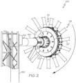
FIG. 2 is a perspective view of a portion of the rotating manifold ofFIG. 1 ; -
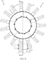
FIG. 3 is a perspective view of a portion of the rotating manifold ofFIG. 1 ; -
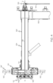
FIG. 4 is a cross-sectional view of a portion of the rotating manifold ofFIG. 1 ; -
FIG. 5 is a perspective view of a portion of the rotating manifold ofFIG. 1 ; -
FIG. 6 is an exploded perspective view of a portion of the rotating manifold ofFIG. 1 ; -
FIG. 7 is a perspective view of a portion of the rotating manifold ofFIG. 1 ; -
FIG. 8 is front perspective view of a portion of the rotating manifold ofFIG. 1 ; -
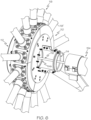
FIG. 9 is a cross-sectional schematic of a portion of the rotating manifold ofFIG. 1 ; -
FIG. 10 is a cross-sectional schematic of a system for vacuum bagging a composite layup; -
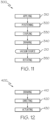
FIG. 11 is a flow diagram of a method for vacuum bagging a composite layup; -
FIG. 12 isa flow diagram of a method for drawing a vacuum through the system ofFIG. 10 ; -
FIG. 13 is a flow diagram of an aircraft manufacturing and service methodology; and -
FIG. 14 is a schematic block diagram of an example of an aircraft. - The following detailed description refers to the accompanying drawings, which illustrate specific examples described by the present disclosure. Other examples having different structures and operations do not depart from the scope of the present disclosure. Like reference numerals may refer to the same feature, element, or component in the different drawings.
- Illustrative, non-exhaustive examples, which may be, but are not necessarily, claimed, of the subject matter according the present disclosure are provided below. Reference herein to "example" means that one or more feature, structure, element, component, characteristic, and/or operational step described in connection with the example is included in at least one aspect, embodiment, and/or implementation of the subject matter according to the present disclosure. Thus, the phrases "an example," "another example," "one or more examples," and similar language throughout the present disclosure may, but do not necessarily, refer to the same example. Further, the subject matter characterizing any one example may, but does not necessarily, include the subject matter characterizing any other example. Moreover, the subject matter characterizing any one example may be, but is not necessarily, combined with the subject matter characterizing any other example.
- Referring to
FIG. 1 , disclosed is arotating manifold 100. Therotating manifold 100 is designed for high volume vacuum bagging for compaction of composite materials. Therotating manifold 100 may include a modular high volume plenum system utilizing a rotational plenum design where high volume vacuum draw is distributed with compressed air to a plurality of pneumatically actuated vacuum valve assemblies via a plurality of conduits. In one example, the subcomponents of the modular high volume plenum system are held together via magnets for easy assembly and disassembly. - Still referring to
Fig. 1 , in one or more examples, therotating manifold 100 includes ahub 110 and acompressed air line 116 housed in theaxle 154, seeFIG. 2 . Thehub 110 is rotatable relative to thecompressed air line 116 about an axis of rotation A, seeFIG. 4 . In one example, thecompressed air line 116 is housed in anaxle 154 such that thehub 110 is rotatable relative to theaxle 154 and a center axis A defined by theaxle 154, seeFIG. 4 . Theaxle 154 may be of any desired diameter for use with therotating manifold 100. In one example, theaxle 154 is approximately 5" in diameter. Further, in one example, thehub 110 may be rotatable about theaxle 154 via abearing 114 located on an outside surface of thehub 110. Thehub 110 may be rotatable about theaxle 154 via both thebearing 114 and asecond bearing 114b located on an outside surface of thehub 110, seeFIG. 6 . - The
compressed air line 116 passes through thehub 110 and is in fluid communication with thecompressed air manifold 160 which is housed inside thecompressed air hub 112. Thecompressed air line 116, seeFIG. 4 , may extend beyond theaxle 154 and may further extend perpendicular to theaxle 154 via a rotational compressedair elbow fitting 152. The rotational compressedair elbow fitting 152 may be configured to maintain necessary supply of compressed air through thecompressed air line 116. - Referring to
FIG. 4 , in one or more examples, theaxle 154 further includes avacuum line 150 in fluid communication with thehub 110. Thevacuum line 150 is configured to selectively draw vacuum through thehub 110. In one example, thevacuum line 150 is housed within theaxle 154, seeFIG. 9 , such that it surrounds thecompressed air line 116. Thevacuum line 150 may pivot to extend perpendicular to theaxle 154 to couple with avacuum source 210. Thecompressed air line 116 andvacuum line 150 are both housed inside theaxle 154 and may both have a center axis A. - Referring to
FIG. 3 ,FIG. 4 , andFIG. 5 , in one or more examples, thehub 110 may further be coupled with acompressed air hub 112. Thecompressed air hub 112 houses acompressed air manifold 160. Thecompressed air manifold 160 includes a plurality ofports 162 in fluid communication with thecompressed air line 116. Each port 162' of the plurality ofports 162 may be individually controllable such that each may distribute compressed air based upon automated or manual control. - Referring to
FIG. 6 , therotating manifold 100 further includes a plurality ofconduits 118 connected to thehub 110. Each conduit 118' of the plurality ofconduits 118 is in fluid communication with thevacuum line 150 such that each is configured to draw vacuum. Further, each conduit 118' of the plurality ofconduits 118 includes a compressed air line arm 116' that is in fluid communication with thecompressed air line 116 via thecompressed air manifold 160, seeFIG. 4 . In one example, each conduit 118' of the plurality ofconduits 118 radially extends from thehub 110. Each conduit 118' of the plurality ofconduits 118 may comprise an elastic material, such as a rubber material. In one example, each conduit 118' of the plurality ofconduits 118 may be at least one of a tube, a hose, and a pipe. In one or more examples, the plurality ofconduits 118 are substantially equidistantly distributed about thehub 110. Further, in another example, each conduit 118' of the plurality ofconduits 118 is magnetically connected to thehub 110. - Referring to
FIG. 7 andFIG. 8 , in one or more examples, each conduit 118' of the plurality ofconduits 118 includes avacuum valve assembly 120.FIG. 7 andFIG. 8 illustrate perspective views of thevacuum valve assembly 120 portion of the rotating manifold. Thevacuum valve assembly 120 may include a movable sealing member, such as aplunger 130. Theplunger 130 is configured to move between at least two positions to block or allow vacuum draw based upon anactuator 124. Thevacuum valve assembly 120 may further include avalve 122 configured to control vacuum flow through thevacuum valve assembly 120. In one example, thevalve 122 is pneumatically actuatable between at least a first position and a second position. In another example, thevalve 122 is a pneumatic compressed air valve that controls anactuator 124 to actuate theplunger 130. Upon pressure from thecompressed air line 116, thevalve 122 supplies air pressure to actuate theactuator 124 for releasing theplunger 130 to an open position to allow vacuum draw from thevacuum line 150. - Referring to
FIG. 10 , in one or more examples, thehub 110 includes a plurality ofvacuum ports 140 configured to engage the plurality ofconduits 118. In one example, each vacuum port 140' of the plurality ofvacuum ports 140 includes avalve 142 configured to selectively control vacuum flow through each conduit 118' of the plurality ofconduits 118. Thevalve 142 may be automated or manually controlled. - Referring to
FIG. 10 , also disclosed is asystem 200 for vacuum bagging acomposite layup 260. Thesystem 200 is designed for effective compaction of large composite structures, and particularly for fuselage structures for aircrafts. Thecomposite layup 260 includes at least one ply of composite material (e.g., a composite ply) placed on (e.g., over) atool 250. Thecomposite layup 260 can include any number (e.g., one or more) of composite plies. The composite material includes a reinforcement material embedded in a polymeric matrix material. In one or more examples, the composite material is pre-impregnated ("pre-preg") thermoset composite material. - Still referring to
FIG. 10 , thesystem 200 includes arotating manifold 100. therotating manifold 100 includes ahub 110 and acompressed air line 116 housed in thehub 110. Thehub 110 is rotatable relative to thecompressed air line 116 about an axis of rotation A. In one example, thecompressed air line 116 is housed in anaxle 154 such that thehub 110 is rotatable relative to theaxle 154 and a center axis A defined by theaxle 154, seeFIG. 4 . In one example, thehub 110 is rotatable about theaxle 154 via abearing 114 located on an outside surface of thehub 110. Thehub 110 may be rotatable about theaxle 154 via both thebearing 114 and asecond bearing 114b located on an outside surface of thehub 110, seeFIG. 6 . - Referring to
FIG. 4 , in one or more examples, theaxle 154 further includes avacuum line 150 in fluid communication with thehub 110 via theaxle 154. Thevacuum line 150 is configured to selectively draw vacuum through thehub 110 by way of thevacuum source 210. In one example, thevacuum line 150 is housed within theaxle 154, seeFIG. 9 , such that it surrounds thecompressed air line 116. - The
rotating manifold 100 of thesystem 200 further includes a plurality ofconduits 118 connected to thehub 110. Each conduit 118' of the plurality ofconduits 118 is in fluid communication with thecompressed air line 116. In one example, each conduit 118' of the plurality ofconduits 118 is connected to thehub 110 with a magnet. In another example, each conduit 118' of the plurality ofconduits 118 comprises avacuum valve assembly 120. - The
system 200 further includes avacuum source 210 in fluid communication with therotating manifold 100 by way of thehub 110 viavacuum line 150 within theaxle 154. Thevacuum source 210 may draw any amount of vacuum suitable for the intended application, such as a high flow vacuum draw. In one example, thevacuum source 210 draws at least 100 cubic feet per minute. - Referring to
FIG. 10 , thesystem 200 includes avacuum bag 240. In one example, thevacuum bag 240 is positioned on an outside surface of thecomposite layup 260. Thevacuum bag 240 includes animpermeable layer 242. Theimpermeable layer 242 is substantially impermeable to fluids, including air. In one example, theimpermeable layer 242 comprises a polymeric material. In another example, the impermeable layer 242comprises rubber. In one specific, non-limiting example, theimpermeable layer 242 comprises a Mosites™ rubber sheet. Thevacuum bag 240 further includes aflow media layer 244. In on example, theflow media layer 244 comprises a biplanar mesh. In another example, theflow media layer 244 is a sheet of material, such as a biplanar mesh. - Referring to
FIG. 1 andFIG. 10 , in one or more example, thesystem 200 further includes atool 250. Thetool 250 may be any size or configuration based upon the desired structure. In one example, thetool 250 may be a mandrel. In one specific example, thetool 250 is a drum-shapedmandrel 252. - Referring to
FIG. 11 , disclosed is amethod 300 of vacuum bagging acomposite layup 260 over a drum-shapedmandrel 252. Themethod 300 includes positioning 320 avacuum bag 240 into engagement with thecomposite layup 260. Thevacuum bag 240 includes animpermeable layer 242. Theimpermeable layer 242 is substantially impermeable to fluids, including air. In one example, theimpermeable layer 242 comprises a polymeric material. In another example, the impermeable layer 242comprises rubber. In one specific, non-limiting example, theimpermeable layer 242 comprises a Mosites™ rubber sheet. Thevacuum bag 240 further includes aflow media layer 244. In on example, theflow media layer 244 comprises a biplanar mesh. In another example, theflow media layer 244 is a sheet of material, such as a biplanar mesh. - Still referring to
FIG. 11 , themethod 300 includes coupling 330 arotating manifold 100 with thevacuum bag 240. Therotating manifold 100 includes ahub 110 and acompressed air line 116 housed in thehub 110. Therotating manifold 100 of themethod 300 further includes a plurality ofconduits 118 in fluid communication with thecompressed air line 116 by way of thehub 110, wherein thehub 110 is rotatable relative to thecompressed air line 116. In one example, thecoupling 330 comprises positioning the plurality ofconduits 118 into engagement with thevacuum bag 240. - The
method 300 further includes drawing 340 vacuum from thevacuum bag 240 via thevacuum source 210 by way of therotating manifold 100. Referring toFIG. 11 , themethod 300 further includes applying 310 thecomposite layup 260 to an outside surface of the drum-shapedmandrel 252 prior to thepositioning 320. In one or more examples, themethod 300 further includes rotating 350 the drum-shapedmandrel 252 simultaneously with the drawing 340. - Referring to
FIG. 12 , in one or more examples, disclosed is amethod 400 for drawing vacuum through thesystem 200. In one example, themethod 400 includes drawing 410 air though thecompressed air line 116 into thehub 110. Themethod 400 further includes directing 420 the air through the plurality ofconduits 118 via thehub 110. Themethod 400 further includes actuating 430 thevacuum valve assembly 120 to enable vacuum draw through thevacuum bag 240. Upon actuating 430, vacuum may be drawn via eachvacuum valve assembly 120 in fluid communication with thevacuum line 150 by way of thevacuum source 210. - Examples of the present disclosure may be described in the context of aircraft manufacturing and
service method 1100 as shown inFIG. 13 andaircraft 1102 as shown inFIG. 14 . During pre-production,service method 1100 may include specification and design (block 1104) ofaircraft 1102 and material procurement (Block 1106). During production, component and subassembly manufacturing (Block 1108) and system integration (Block 1110) ofaircraft 1102 may take place. Thereafter,aircraft 1102 may go through certification and delivery (Block 1112) to be placed in service (Block 1114). While in service,aircraft 1102 may be scheduled for routine maintenance and service (Block 1116). Routine maintenance and service may include modification, reconfiguration, refurbishment, etc. of one or more systems ofaircraft 1102. - Each of the processes of
service method 1100 may be performed or carried out by a system integrator, a third party, and/or an operator (e.g., a customer). For the purposes of this description, a system integrator may include, without limitation, any number of aircraft manufacturers and major-system subcontractors; a third party may include, without limitation, any number of vendors, subcontractors, and suppliers; and an operator may be an airline, leasing company, military entity, service organization, and so on. - As shown in
FIG. 14 ,aircraft 1102 produced byservice method 1100 may includeairframe 1118 with a plurality of high-level systems 1120 and interior 1122. Examples of high-level systems 1120 include one or more ofpropulsion system 1124,electrical system 1126,hydraulic system 1128, andenvironmental system 1130. Any number of other systems may be included. Although an aerospace example is shown, the principles disclosed herein may be applied to other industries, such as the automotive industry. Accordingly, in addition toaircraft 1102, the principles disclosed herein may apply to other vehicles, e.g., land vehicles, marine vehicles, space vehicles, etc. - Rotating manifold(s), system(s) and method(s) shown or described herein may be employed during any one or more of the stages of the manufacturing and
service method 1100. For example, components or subassemblies corresponding to component and subassembly manufacturing (block 1108) may be fabricated or manufactured in a manner similar to components or subassemblies produced whileaircraft 1102 is in service (Block 1114). Also, one or more examples of the rotating manifold(s), system(s) and method(s), or combination thereof may be utilized during production stages component and subassembly manufacturing (Block 1108) and system integration (Block 1110), for example, by substantially expediting assembly of or reducing the cost ofaircraft 1102. Similarly, one or more examples of the system or method realizations, or a combination thereof, may be utilized, for example and without limitation, whileaircraft 1102 is in service (Block 1114) and/or during maintenance and service (Block 1116). - Further, the disclosure comprises embodiments according to the following clauses:
- Clause 1. A rotating manifold (100) comprising:
- an axle (154);
- a hub (110) rotatable relative to the axle (154) about an axis of rotation (A);
- a compressed air line (116) housed in the axle (154);
a plurality of conduits (118) connected to the hub (110), wherein each conduit (118') of the plurality of conduits (118) is in fluid communication with the vacuum line (150) and wherein each conduit (118') of the plurality of conduits (118) houses a compressed air line arm (116') in fluid communication with the compressed air line (116). - Clause 2. The rotating manifold (100) according to Clause 1, wherein the plurality of conduits (118) are substantially equidistantly distributed about the hub (110).
- Clause 3. The rotating manifold (100) according to Clause 1 or 2, wherein each conduit (118') of the plurality of conduits (118) radially extends from the hub (110).
-
Clause 4. The rotating manifold (100) according to any of Clauses 1 to 3, wherein each conduit (118') of the plurality of conduits (118) comprises at least one of a tube, a hose, and a pipe. - Clause 5. The rotating manifold (100) according to any of Clauses 1 to 4, wherein each conduit (118') of the plurality of conduits (118) is magnetically connected to the hub (110).
- Clause 6. The rotating manifold (100) according to any of Clauses 1 to 5, wherein each conduit (118') of the plurality of conduits (118) comprises a vacuum valve assembly (120).
- Clause 7. The rotating manifold (100) according to Clause 6, wherein the vacuum valve assembly (120) comprises a plunger (130).
- Clause 8. The rotating manifold (100) according to Clause 6 or 7, wherein the vacuum valve assembly (120) comprises a valve (122) configured to control vacuum flow through the vacuum valve assembly (120).
- Clause 9. The rotating manifold (100) according to Clause 8, wherein the valve (122) is pneumatically actuatable between at least a first position and a second position.
- Clause 10. The rotating manifold (100) according to Clause 8 or 9, wherein the vacuum valve assembly (120) comprises an actuator (124).
- Clause 11. The rotating manifold (100) according to any of Clauses 1 to 10, further comprising a bearing (114) located between the hub (110) and the axle (154).
- Clause 12. The rotating manifold (100) according to any of Clauses 1 to 11, wherein the hub (110) comprises a plurality of vacuum ports (140) configured to engage the plurality of conduits (118).
- Clause 13. The rotating manifold (100) according to Clause 12, wherein each vacuum port (140') of the plurality of vacuum ports (140) comprises a valve (142) configured to selectively control vacuum flow through each conduit (118') of the plurality of conduits (118).
- Clause 14. A system (200) for vacuum bagging a composite layup (260), the system (200) comprising:
- a rotating manifold (100), the rotating manifold (100) comprising:
- an axle (154);
- a hub (110) rotatable relative to the axle (154) about an axis of rotation (A);
- a compressed air line (116) housed in the axle (154);
a plurality of conduits (118) connected to the hub (110), wherein each conduit (118') of the plurality of conduits (118) is in fluid communication with the vacuum line (150) and compressed air line (116), wherein each conduit (118') of the plurality of conduits (118) houses a compressed air line arm (116') in fluid communication with the compressed air line (116); and
a vacuum source (210) in fluid communication with the rotating manifold (100) by way of the vacuum line (150). - a rotating manifold (100), the rotating manifold (100) comprising:
- Clause 15. The system (200) according to Clause 14, wherein each conduit (118) of the plurality of conduits (118) is connected to the hub (110) with a magnet.
- Clause 16. The system (200) according to Clause 14 or 15, wherein each conduit (118) of the plurality of conduits (118) comprises a vacuum valve assembly (120).
- Clause 17. The system (200) according to any of Clauses 14 to 16, wherein the vacuum source (210) draws at least 100 cubic feet per minute.
- Clause 18. The system (200) according to any of Clauses 14 to 17, further comprising a vacuum bag (240) on an outside surface of the composite layup (260).
- Clause 19. The system (200) according to any of Clauses 14 to 18, further comprising a tool (250).
- Clause 20. The system (200) of Clause 19, wherein the tool (250) is a drum-shaped mandrel (252).
- Clause 21. A method (300) of vacuum bagging a composite layup (260) over a drum-shaped mandrel (252), the method (300) comprising:
positioning (320) a vacuum bag (240) into engagement with the composite layup (260);- coupling (330) a rotating manifold (100) with the vacuum bag (240); and
- drawing (340) vacuum from the vacuum bag (240) by way of the rotating manifold (100).
- Clause 22. The method (300) of Clause 21, wherein the rotating manifold (100) comprises:
- an axle (154);
- a hub (110) rotatable relative to the axle (154) about an axis of rotation (A);
- a compressed air line (116) housed in the axle (154);
a plurality of conduits (118) connected to the hub (110), wherein each conduit (118') of the plurality of conduits (118) is in fluid communication with the vacuum line (150) and wherein each conduit (118') of the plurality of conduits (118) houses a compressed air line arm (116') in fluid communication with the compressed air line (116). - Clause 23. The method (300) of Clause 22, wherein the coupling (330) comprises positioning the plurality of conduits (118) into engagement with the vacuum bag (240).
- Clause 24. The method (300) according to Clause 22 or 23, further comprising applying (310) the composite layup (260) to an outside surface of the drum-shaped mandrel (252) prior to the positioning (320).
- Clause 25. The method (300) according to any of Clauses 21 to 24, further comprising rotating (350) the drum-shaped mandrel (252) simultaneously with the drawing (340).
- Clause 26. A method (400) for drawing vacuum through the system (200) of any of Clauses 18 to 20, the method (400) comprising:
- drawing (410) air though the compressed air line (116) into the hub (110);
- directing (420) the air through the plurality of conduits (118) via the hub (110); and
- actuating (430) a vacuum valve assembly (120) to enable vacuum draw through the vacuum bag (240).
- Different examples of the rotating manifold(s), system(s) and method(s) disclosed herein include a variety of components, features, and functionalities. It should be understood that the various examples of the rotating manifold(s), system(s) and method(s) disclosed herein may include any of the components, features, and functionalities of any of the other examples of the rotating manifold(s), system(s) and method(s) disclosed herein in any combination, and all of such possibilities are intended to be within the scope of the present disclosure.
- Many modifications of examples set forth herein will come to mind to one skilled in the art to which the present disclosure pertains having the benefit of the teachings presented in the foregoing descriptions and the associated drawings.
- Therefore, it is to be understood that the present disclosure is not to be limited to the specific examples illustrated and that modifications and other examples are intended to be included within the scope of the appended claims. Moreover, although the foregoing description and the associated drawings describe examples of the present disclosure in the context of certain illustrative combinations of elements and/or functions, it should be appreciated that different combinations of elements and/or functions may be provided by alternative implementations without departing from the scope of the appended claims. Accordingly, parenthetical reference numerals in the appended claims are presented for illustrative purposes only and are not intended to limit the scope of the claimed subject matter to the specific examples provided in the present disclosure.
a plurality of conduits connected to the hub, wherein each conduit of the plurality of conduits is in fluid communication with the vacuum line and wherein each conduit of the plurality of conduits houses a compressed air line arm in fluid communication with the compressed air line.
a plurality of conduits connected to the hub, wherein each conduit of the plurality of conduits is in fluid communication with the vacuum line and compressed air line, wherein each conduit of the plurality of conduits houses a compressed air line arm in fluid communication with the compressed air line; and
a vacuum source in fluid communication with the rotating manifold (100) by way of the vacuum line.
Claims (15)
- A rotating manifold (100) comprising:an axle (154);a hub (110) rotatable relative to the axle (154) about an axis of rotation (A);a compressed air line (116) housed in the axle (154);a vacuum line (150) in fluid communication with the hub (110); and
a plurality of conduits (118) connected to the hub (110), wherein each conduit (118') of the plurality of conduits (118) is in fluid communication with the vacuum line (150) and wherein each conduit (118') of the plurality of conduits (118) houses a compressed air line arm (116') in fluid communication with the compressed air line (116). - The rotating manifold (100) according to Claim 1, wherein the plurality of conduits (118) are substantially equidistantly distributed about the hub (110).
- The rotating manifold (100) according to Claim 1 or 2, wherein each conduit (118') of the plurality of conduits (118) radially extends from the hub (110).
- The rotating manifold (100) according to any of Claims 1 to 3, wherein each conduit (118') of the plurality of conduits (118) comprises at least one of a tube, a hose, and a pipe.
- The rotating manifold (100) according to any of Claims 1 to 4, wherein each conduit (118') of the plurality of conduits (118) is magnetically connected to the hub (110).
- The rotating manifold (100) according to any of Claims 1 to 5, wherein each conduit (118') of the plurality of conduits (118) comprises a vacuum valve assembly (120).
- The rotating manifold (100) according to Claim 6, wherein the vacuum valve assembly (120) comprises a plunger (130), wherein the vacuum valve assembly (120) comprises a valve (122) configured to control vacuum flow through the vacuum valve assembly (120), wherein the valve (122) is pneumatically actuatable between at least a first position and a second position, wherein the vacuum valve assembly (120) comprises an actuator (124).
- The rotating manifold (100) according to any of Claims 1 to 7, further comprising a bearing (114) located between the hub (110) and the axle (154).
- The rotating manifold (100) according to any of Claims 1 to 8, wherein the hub (110) comprises a plurality of vacuum ports (140) configured to engage the plurality of conduits (118), wherein each vacuum port (140') of the plurality of vacuum ports (140) comprises a valve (142) configured to selectively control vacuum flow through each conduit (118') of the plurality of conduits (118).
- A system (200) for vacuum bagging a composite layup (260), the system (200) comprising:a rotating manifold (100), the rotating manifold (100) comprising:an axle (154);a hub (110) rotatable relative to the axle (154) about an axis of rotation (A);a compressed air line (116) housed in the axle (154);a vacuum line (150) in fluid communication with the hub (110); and
a plurality of conduits (118) connected to the hub (110), wherein each conduit (118') of the plurality of conduits (118) is in fluid communication with the vacuum line (150) and compressed air line (116), wherein each conduit (118') of the plurality of conduits (118) houses a compressed air line arm (116') in fluid communication with the compressed air line (116); and
a vacuum source (210) in fluid communication with the rotating manifold (100) by way of the vacuum line (150). - A method (300) of vacuum bagging a composite layup (260) over a drum-shaped mandrel (252), the method (300) comprising:positioning (320) a vacuum bag (240) into engagement with the composite layup (260);coupling (330) a rotating manifold (100) with the vacuum bag (240); anddrawing (340) vacuum from the vacuum bag (240) by way of the rotating manifold (100).
- The method (300) of Claim 11, wherein the rotating manifold (100) comprises:an axle (154);a hub (110) rotatable relative to the axle (154) about an axis of rotation (A);a compressed air line (116) housed in the axle (154);a vacuum line (150) in fluid communication with the hub (110); and
a plurality of conduits (118) connected to the hub (110), wherein each conduit (118') of the plurality of conduits (118) is in fluid communication with the vacuum line (150) and wherein each conduit (118') of the plurality of conduits (118) houses a compressed air line arm (116') in fluid communication with the compressed air line (116). - The method (300) of Claim 12, wherein the coupling (330) comprises positioning the plurality of conduits (118) into engagement with the vacuum bag (240).
- The method (300) according to Claim 12 or 13, further comprising applying (310) the composite layup (260) to an outside surface of the drum-shaped mandrel (252) prior to the positioning (320).
- The method (300) according to any of Claims 11 to 14, further comprising rotating (350) the drum-shaped mandrel (252) simultaneously with the drawing (340).
Applications Claiming Priority (1)
| Application Number | Priority Date | Filing Date | Title |
|---|---|---|---|
| US17/662,455 US12030262B2 (en) | 2022-05-09 | 2022-05-09 | Rotating manifolds and associated systems and methods for vacuum bagging large composite structures |
Publications (2)
| Publication Number | Publication Date |
|---|---|
| EP4275872A1 true EP4275872A1 (en) | 2023-11-15 |
| EP4275872B1 EP4275872B1 (en) | 2025-01-29 |
Family
ID=85150840
Family Applications (1)
| Application Number | Title | Priority Date | Filing Date |
|---|---|---|---|
| EP23153964.4A Active EP4275872B1 (en) | 2022-05-09 | 2023-01-30 | Rotating manifolds and associated systems and methods for vacuum bagging large composite structures |
Country Status (3)
| Country | Link |
|---|---|
| US (1) | US12030262B2 (en) |
| EP (1) | EP4275872B1 (en) |
| JP (1) | JP2023166337A (en) |
Citations (2)
| Publication number | Priority date | Publication date | Assignee | Title |
|---|---|---|---|---|
| EP2623302A1 (en) * | 2012-01-31 | 2013-08-07 | Eire Composites | Agitation assisted vacuum bagging process and apparatus therefor |
| US20140367039A1 (en) * | 2013-02-15 | 2014-12-18 | The Boeing Company | Systems and methods for compacting a charge of composite material |
Family Cites Families (5)
| Publication number | Priority date | Publication date | Assignee | Title |
|---|---|---|---|---|
| US3865525A (en) * | 1972-06-26 | 1975-02-11 | Owens Corning Fiberglass Corp | Apparatus for coating three dimensional objects |
| US8652388B2 (en) * | 2005-12-15 | 2014-02-18 | The Boeing Company | Rotational vacuum assisted resin transfer molding |
| US11312026B2 (en) | 2019-10-10 | 2022-04-26 | The Boeing Company | Placement and compaction of objects via vacuum |
| WO2021173910A1 (en) * | 2020-02-28 | 2021-09-02 | Tpi Composites, Inc. | Pre-kitted infusion package including vacuum bag with built-in infusion channels and consumables |
| US12030266B2 (en) | 2020-03-13 | 2024-07-09 | The Boeing Company | Scrolls that vacuum secure objects to complex surfaces |
-
2022
- 2022-05-09 US US17/662,455 patent/US12030262B2/en active Active
-
2023
- 2023-01-30 EP EP23153964.4A patent/EP4275872B1/en active Active
- 2023-05-01 JP JP2023075417A patent/JP2023166337A/en active Pending
Patent Citations (2)
| Publication number | Priority date | Publication date | Assignee | Title |
|---|---|---|---|---|
| EP2623302A1 (en) * | 2012-01-31 | 2013-08-07 | Eire Composites | Agitation assisted vacuum bagging process and apparatus therefor |
| US20140367039A1 (en) * | 2013-02-15 | 2014-12-18 | The Boeing Company | Systems and methods for compacting a charge of composite material |
Non-Patent Citations (2)
| Title |
|---|
| B-COMMAND: "Compact Slip Ring Solutions", 31 December 2020 (2020-12-31), pages 1 - 3, XP002809694, Retrieved from the Internet <URL:https://www.rotarx.com/wp-content/uploads/B-COMMAND-rotarX-Product-Overview-EN.pdf> [retrieved on 20230705] * |
| DSTI: "Food & beverage solutions, Packaging & Processing", 22 October 2020 (2020-10-22), pages 1 - 2, XP002809693, Retrieved from the Internet <URL:https://web.archive.org/web/20201022065414/https://www.dsti.com/pdfs/catalogs/DSTI-Packaging-Processing.pdf> [retrieved on 20230705] * |
Also Published As
| Publication number | Publication date |
|---|---|
| EP4275872B1 (en) | 2025-01-29 |
| US20230356481A1 (en) | 2023-11-09 |
| JP2023166337A (en) | 2023-11-21 |
| US12030262B2 (en) | 2024-07-09 |
Similar Documents
| Publication | Publication Date | Title |
|---|---|---|
| EP1388407B2 (en) | Preforming thermoplastic ducts | |
| CA2434870C (en) | Consolidation joining of thermoplastic laminate ducts | |
| EP3804968B1 (en) | Placement and compaction of objects via vacuum | |
| US10751955B2 (en) | Unitized composite structure manufacturing system | |
| US9586344B2 (en) | Method and system of forming a releasable support and method of pre-cure removal of a composite laminate | |
| US12030262B2 (en) | Rotating manifolds and associated systems and methods for vacuum bagging large composite structures | |
| US11964459B1 (en) | Systems and methods for removing a backing from a ply of composite material | |
| US12304159B2 (en) | Apparatus, system and method for applying composite layups | |
| EP4194172A1 (en) | Pliable structures and associated methods and systems for replicating a contour of a surface | |
| US20140116624A1 (en) | Pressure Debulking System | |
| US11919261B2 (en) | Automated removal apparatus, system, and method for selectively removing trimmed portions of a laminated ply in a ply-by-ply fabrication process | |
| US12472705B2 (en) | Methods for configuring a shape of a tool and associated systems and methods for manufacturing a composite structure | |
| EP4197719B1 (en) | Gripping apparatus and associated systems and methods for gripping flexible materials | |
| US12605908B2 (en) | Systems and methods for forming composite workpieces | |
| EP4406717A1 (en) | Method for preforming a workpiece, composite manufacturing method and system associcated therewith | |
| EP4491382A1 (en) | Curing tool assemblies, methods and systems for composite manufacturing | |
| US10823449B2 (en) | Composite duct with reinforcement |
Legal Events
| Date | Code | Title | Description |
|---|---|---|---|
| PUAI | Public reference made under article 153(3) epc to a published international application that has entered the european phase |
Free format text: ORIGINAL CODE: 0009012 |
|
| STAA | Information on the status of an ep patent application or granted ep patent |
Free format text: STATUS: THE APPLICATION HAS BEEN PUBLISHED |
|
| AK | Designated contracting states |
Kind code of ref document: A1 Designated state(s): AL AT BE BG CH CY CZ DE DK EE ES FI FR GB GR HR HU IE IS IT LI LT LU LV MC ME MK MT NL NO PL PT RO RS SE SI SK SM TR |
|
| STAA | Information on the status of an ep patent application or granted ep patent |
Free format text: STATUS: REQUEST FOR EXAMINATION WAS MADE |
|
| 17P | Request for examination filed |
Effective date: 20240416 |
|
| RBV | Designated contracting states (corrected) |
Designated state(s): AL AT BE BG CH CY CZ DE DK EE ES FI FR GB GR HR HU IE IS IT LI LT LU LV MC ME MK MT NL NO PL PT RO RS SE SI SK SM TR |
|
| GRAP | Despatch of communication of intention to grant a patent |
Free format text: ORIGINAL CODE: EPIDOSNIGR1 |
|
| STAA | Information on the status of an ep patent application or granted ep patent |
Free format text: STATUS: GRANT OF PATENT IS INTENDED |
|
| RIC1 | Information provided on ipc code assigned before grant |
Ipc: F16L 41/03 20060101ALI20240826BHEP Ipc: F16L 39/04 20060101ALI20240826BHEP Ipc: B29C 70/54 20060101ALI20240826BHEP Ipc: B29C 37/00 20060101ALI20240826BHEP Ipc: B29C 70/44 20060101AFI20240826BHEP |
|
| INTG | Intention to grant announced |
Effective date: 20240906 |
|
| GRAS | Grant fee paid |
Free format text: ORIGINAL CODE: EPIDOSNIGR3 |
|
| P01 | Opt-out of the competence of the unified patent court (upc) registered |
Free format text: CASE NUMBER: APP_61544/2024 Effective date: 20241118 |
|
| GRAA | (expected) grant |
Free format text: ORIGINAL CODE: 0009210 |
|
| STAA | Information on the status of an ep patent application or granted ep patent |
Free format text: STATUS: THE PATENT HAS BEEN GRANTED |
|
| AK | Designated contracting states |
Kind code of ref document: B1 Designated state(s): AL AT BE BG CH CY CZ DE DK EE ES FI FR GB GR HR HU IE IS IT LI LT LU LV MC ME MK MT NL NO PL PT RO RS SE SI SK SM TR |
|
| REG | Reference to a national code |
Ref country code: GB Ref legal event code: FG4D |
|
| REG | Reference to a national code |
Ref country code: CH Ref legal event code: EP |
|
| REG | Reference to a national code |
Ref country code: DE Ref legal event code: R096 Ref document number: 602023001800 Country of ref document: DE |
|
| REG | Reference to a national code |
Ref country code: IE Ref legal event code: FG4D |
|
| PGFP | Annual fee paid to national office [announced via postgrant information from national office to epo] |
Ref country code: AT Payment date: 20250417 Year of fee payment: 3 |
|
| REG | Reference to a national code |
Ref country code: NL Ref legal event code: MP Effective date: 20250129 |
|
| PG25 | Lapsed in a contracting state [announced via postgrant information from national office to epo] |
Ref country code: NL Free format text: LAPSE BECAUSE OF FAILURE TO SUBMIT A TRANSLATION OF THE DESCRIPTION OR TO PAY THE FEE WITHIN THE PRESCRIBED TIME-LIMIT Effective date: 20250129 |
|
| PG25 | Lapsed in a contracting state [announced via postgrant information from national office to epo] |
Ref country code: RS Free format text: LAPSE BECAUSE OF FAILURE TO SUBMIT A TRANSLATION OF THE DESCRIPTION OR TO PAY THE FEE WITHIN THE PRESCRIBED TIME-LIMIT Effective date: 20250429 |
|
| PG25 | Lapsed in a contracting state [announced via postgrant information from national office to epo] |
Ref country code: FI Free format text: LAPSE BECAUSE OF FAILURE TO SUBMIT A TRANSLATION OF THE DESCRIPTION OR TO PAY THE FEE WITHIN THE PRESCRIBED TIME-LIMIT Effective date: 20250129 |
|
| PG25 | Lapsed in a contracting state [announced via postgrant information from national office to epo] |
Ref country code: PL Free format text: LAPSE BECAUSE OF FAILURE TO SUBMIT A TRANSLATION OF THE DESCRIPTION OR TO PAY THE FEE WITHIN THE PRESCRIBED TIME-LIMIT Effective date: 20250129 |
|
| PG25 | Lapsed in a contracting state [announced via postgrant information from national office to epo] |
Ref country code: ES Free format text: LAPSE BECAUSE OF FAILURE TO SUBMIT A TRANSLATION OF THE DESCRIPTION OR TO PAY THE FEE WITHIN THE PRESCRIBED TIME-LIMIT Effective date: 20250129 |
|
| REG | Reference to a national code |
Ref country code: LT Ref legal event code: MG9D |
|
| PG25 | Lapsed in a contracting state [announced via postgrant information from national office to epo] |
Ref country code: NO Free format text: LAPSE BECAUSE OF FAILURE TO SUBMIT A TRANSLATION OF THE DESCRIPTION OR TO PAY THE FEE WITHIN THE PRESCRIBED TIME-LIMIT Effective date: 20250429 Ref country code: IS Free format text: LAPSE BECAUSE OF FAILURE TO SUBMIT A TRANSLATION OF THE DESCRIPTION OR TO PAY THE FEE WITHIN THE PRESCRIBED TIME-LIMIT Effective date: 20250529 |
|
| REG | Reference to a national code |
Ref country code: AT Ref legal event code: MK05 Ref document number: 1763046 Country of ref document: AT Kind code of ref document: T Effective date: 20250129 |
|
| PG25 | Lapsed in a contracting state [announced via postgrant information from national office to epo] |
Ref country code: HR Free format text: LAPSE BECAUSE OF FAILURE TO SUBMIT A TRANSLATION OF THE DESCRIPTION OR TO PAY THE FEE WITHIN THE PRESCRIBED TIME-LIMIT Effective date: 20250129 |
|
| PG25 | Lapsed in a contracting state [announced via postgrant information from national office to epo] |
Ref country code: LV Free format text: LAPSE BECAUSE OF FAILURE TO SUBMIT A TRANSLATION OF THE DESCRIPTION OR TO PAY THE FEE WITHIN THE PRESCRIBED TIME-LIMIT Effective date: 20250129 Ref country code: PT Free format text: LAPSE BECAUSE OF FAILURE TO SUBMIT A TRANSLATION OF THE DESCRIPTION OR TO PAY THE FEE WITHIN THE PRESCRIBED TIME-LIMIT Effective date: 20250529 |
|
| PG25 | Lapsed in a contracting state [announced via postgrant information from national office to epo] |
Ref country code: BG Free format text: LAPSE BECAUSE OF FAILURE TO SUBMIT A TRANSLATION OF THE DESCRIPTION OR TO PAY THE FEE WITHIN THE PRESCRIBED TIME-LIMIT Effective date: 20250129 Ref country code: GR Free format text: LAPSE BECAUSE OF FAILURE TO SUBMIT A TRANSLATION OF THE DESCRIPTION OR TO PAY THE FEE WITHIN THE PRESCRIBED TIME-LIMIT Effective date: 20250430 |
|
| PG25 | Lapsed in a contracting state [announced via postgrant information from national office to epo] |
Ref country code: AT Free format text: LAPSE BECAUSE OF FAILURE TO SUBMIT A TRANSLATION OF THE DESCRIPTION OR TO PAY THE FEE WITHIN THE PRESCRIBED TIME-LIMIT Effective date: 20250129 |
|
| PG25 | Lapsed in a contracting state [announced via postgrant information from national office to epo] |
Ref country code: SE Free format text: LAPSE BECAUSE OF FAILURE TO SUBMIT A TRANSLATION OF THE DESCRIPTION OR TO PAY THE FEE WITHIN THE PRESCRIBED TIME-LIMIT Effective date: 20250129 |
|
| PG25 | Lapsed in a contracting state [announced via postgrant information from national office to epo] |
Ref country code: LU Free format text: LAPSE BECAUSE OF NON-PAYMENT OF DUE FEES Effective date: 20250130 |
|
| PG25 | Lapsed in a contracting state [announced via postgrant information from national office to epo] |
Ref country code: SM Free format text: LAPSE BECAUSE OF FAILURE TO SUBMIT A TRANSLATION OF THE DESCRIPTION OR TO PAY THE FEE WITHIN THE PRESCRIBED TIME-LIMIT Effective date: 20250129 |
|
| PG25 | Lapsed in a contracting state [announced via postgrant information from national office to epo] |
Ref country code: DK Free format text: LAPSE BECAUSE OF FAILURE TO SUBMIT A TRANSLATION OF THE DESCRIPTION OR TO PAY THE FEE WITHIN THE PRESCRIBED TIME-LIMIT Effective date: 20250129 |
|
| PG25 | Lapsed in a contracting state [announced via postgrant information from national office to epo] |
Ref country code: MC Free format text: LAPSE BECAUSE OF FAILURE TO SUBMIT A TRANSLATION OF THE DESCRIPTION OR TO PAY THE FEE WITHIN THE PRESCRIBED TIME-LIMIT Effective date: 20250129 |
|
| PG25 | Lapsed in a contracting state [announced via postgrant information from national office to epo] |
Ref country code: IT Free format text: LAPSE BECAUSE OF FAILURE TO SUBMIT A TRANSLATION OF THE DESCRIPTION OR TO PAY THE FEE WITHIN THE PRESCRIBED TIME-LIMIT Effective date: 20250129 |
|
| PG25 | Lapsed in a contracting state [announced via postgrant information from national office to epo] |
Ref country code: BE Free format text: LAPSE BECAUSE OF NON-PAYMENT OF DUE FEES Effective date: 20250131 |
|
| PG25 | Lapsed in a contracting state [announced via postgrant information from national office to epo] |
Ref country code: EE Free format text: LAPSE BECAUSE OF FAILURE TO SUBMIT A TRANSLATION OF THE DESCRIPTION OR TO PAY THE FEE WITHIN THE PRESCRIBED TIME-LIMIT Effective date: 20250129 Ref country code: CZ Free format text: LAPSE BECAUSE OF FAILURE TO SUBMIT A TRANSLATION OF THE DESCRIPTION OR TO PAY THE FEE WITHIN THE PRESCRIBED TIME-LIMIT Effective date: 20250129 |
|
| REG | Reference to a national code |
Ref country code: BE Ref legal event code: MM Effective date: 20250131 |
|
| PG25 | Lapsed in a contracting state [announced via postgrant information from national office to epo] |
Ref country code: RO Free format text: LAPSE BECAUSE OF FAILURE TO SUBMIT A TRANSLATION OF THE DESCRIPTION OR TO PAY THE FEE WITHIN THE PRESCRIBED TIME-LIMIT Effective date: 20250129 |
|
| PG25 | Lapsed in a contracting state [announced via postgrant information from national office to epo] |
Ref country code: SK Free format text: LAPSE BECAUSE OF FAILURE TO SUBMIT A TRANSLATION OF THE DESCRIPTION OR TO PAY THE FEE WITHIN THE PRESCRIBED TIME-LIMIT Effective date: 20250129 |
|
| REG | Reference to a national code |
Ref country code: DE Ref legal event code: R097 Ref document number: 602023001800 Country of ref document: DE |
|
| PLBE | No opposition filed within time limit |
Free format text: ORIGINAL CODE: 0009261 |
|
| STAA | Information on the status of an ep patent application or granted ep patent |
Free format text: STATUS: NO OPPOSITION FILED WITHIN TIME LIMIT |
|
| 26N | No opposition filed |
Effective date: 20251030 |
|
| PG25 | Lapsed in a contracting state [announced via postgrant information from national office to epo] |
Ref country code: IE Free format text: LAPSE BECAUSE OF NON-PAYMENT OF DUE FEES Effective date: 20250130 |
|
| PGFP | Annual fee paid to national office [announced via postgrant information from national office to epo] |
Ref country code: DE Payment date: 20260128 Year of fee payment: 4 |
|
| PGFP | Annual fee paid to national office [announced via postgrant information from national office to epo] |
Ref country code: FR Payment date: 20260126 Year of fee payment: 4 |