EP4275810A1 - Damage evalulation device and damage evalulation method for press-forming dies - Google Patents
Damage evalulation device and damage evalulation method for press-forming dies Download PDFInfo
- Publication number
- EP4275810A1 EP4275810A1 EP22771139.7A EP22771139A EP4275810A1 EP 4275810 A1 EP4275810 A1 EP 4275810A1 EP 22771139 A EP22771139 A EP 22771139A EP 4275810 A1 EP4275810 A1 EP 4275810A1
- Authority
- EP
- European Patent Office
- Prior art keywords
- press
- die
- dies
- steel material
- forming
- Prior art date
- Legal status (The legal status is an assumption and is not a legal conclusion. Google has not performed a legal analysis and makes no representation as to the accuracy of the status listed.)
- Granted
Links
Images




Classifications
-
- B—PERFORMING OPERATIONS; TRANSPORTING
- B21—MECHANICAL METAL-WORKING WITHOUT ESSENTIALLY REMOVING MATERIAL; PUNCHING METAL
- B21D—WORKING OR PROCESSING OF SHEET METAL OR METAL TUBES, RODS OR PROFILES WITHOUT ESSENTIALLY REMOVING MATERIAL; PUNCHING METAL
- B21D28/00—Shaping by press-cutting; Perforating
- B21D28/24—Perforating, i.e. punching holes
- B21D28/26—Perforating, i.e. punching holes in sheets or flat parts
-
- B—PERFORMING OPERATIONS; TRANSPORTING
- B21—MECHANICAL METAL-WORKING WITHOUT ESSENTIALLY REMOVING MATERIAL; PUNCHING METAL
- B21D—WORKING OR PROCESSING OF SHEET METAL OR METAL TUBES, RODS OR PROFILES WITHOUT ESSENTIALLY REMOVING MATERIAL; PUNCHING METAL
- B21D37/00—Tools as parts of machines covered by this subclass
- B21D37/04—Movable or exchangeable mountings for tools
-
- B—PERFORMING OPERATIONS; TRANSPORTING
- B30—PRESSES
- B30B—PRESSES IN GENERAL
- B30B15/00—Details of, or accessories for, presses; Auxiliary measures in connection with pressing
- B30B15/28—Arrangements for preventing distortion of, or damage to, presses or parts thereof
-
- B—PERFORMING OPERATIONS; TRANSPORTING
- B21—MECHANICAL METAL-WORKING WITHOUT ESSENTIALLY REMOVING MATERIAL; PUNCHING METAL
- B21D—WORKING OR PROCESSING OF SHEET METAL OR METAL TUBES, RODS OR PROFILES WITHOUT ESSENTIALLY REMOVING MATERIAL; PUNCHING METAL
- B21D22/00—Shaping without cutting, by stamping, spinning, or deep-drawing
- B21D22/20—Deep-drawing
-
- B—PERFORMING OPERATIONS; TRANSPORTING
- B21—MECHANICAL METAL-WORKING WITHOUT ESSENTIALLY REMOVING MATERIAL; PUNCHING METAL
- B21D—WORKING OR PROCESSING OF SHEET METAL OR METAL TUBES, RODS OR PROFILES WITHOUT ESSENTIALLY REMOVING MATERIAL; PUNCHING METAL
- B21D22/00—Shaping without cutting, by stamping, spinning, or deep-drawing
- B21D22/20—Deep-drawing
- B21D22/26—Deep-drawing for making peculiarly, e.g. irregularly, shaped articles
-
- B—PERFORMING OPERATIONS; TRANSPORTING
- B21—MECHANICAL METAL-WORKING WITHOUT ESSENTIALLY REMOVING MATERIAL; PUNCHING METAL
- B21D—WORKING OR PROCESSING OF SHEET METAL OR METAL TUBES, RODS OR PROFILES WITHOUT ESSENTIALLY REMOVING MATERIAL; PUNCHING METAL
- B21D24/00—Special deep-drawing arrangements in, or in connection with, presses
- B21D24/16—Additional equipment in association with the tools, e.g. for shearing, for trimming
-
- B—PERFORMING OPERATIONS; TRANSPORTING
- B21—MECHANICAL METAL-WORKING WITHOUT ESSENTIALLY REMOVING MATERIAL; PUNCHING METAL
- B21D—WORKING OR PROCESSING OF SHEET METAL OR METAL TUBES, RODS OR PROFILES WITHOUT ESSENTIALLY REMOVING MATERIAL; PUNCHING METAL
- B21D28/00—Shaping by press-cutting; Perforating
- B21D28/02—Punching blanks or articles with or without obtaining scrap; Notching
- B21D28/10—Incompletely punching in such a manner that the parts are still coherent with the work
-
- B—PERFORMING OPERATIONS; TRANSPORTING
- B21—MECHANICAL METAL-WORKING WITHOUT ESSENTIALLY REMOVING MATERIAL; PUNCHING METAL
- B21D—WORKING OR PROCESSING OF SHEET METAL OR METAL TUBES, RODS OR PROFILES WITHOUT ESSENTIALLY REMOVING MATERIAL; PUNCHING METAL
- B21D35/00—Combined processes according to or processes combined with methods covered by groups B21D1/00 - B21D31/00
- B21D35/001—Shaping combined with punching, e.g. stamping and perforating
-
- B—PERFORMING OPERATIONS; TRANSPORTING
- B21—MECHANICAL METAL-WORKING WITHOUT ESSENTIALLY REMOVING MATERIAL; PUNCHING METAL
- B21D—WORKING OR PROCESSING OF SHEET METAL OR METAL TUBES, RODS OR PROFILES WITHOUT ESSENTIALLY REMOVING MATERIAL; PUNCHING METAL
- B21D37/00—Tools as parts of machines covered by this subclass
- B21D37/01—Selection of materials
-
- B—PERFORMING OPERATIONS; TRANSPORTING
- B21—MECHANICAL METAL-WORKING WITHOUT ESSENTIALLY REMOVING MATERIAL; PUNCHING METAL
- B21D—WORKING OR PROCESSING OF SHEET METAL OR METAL TUBES, RODS OR PROFILES WITHOUT ESSENTIALLY REMOVING MATERIAL; PUNCHING METAL
- B21D37/00—Tools as parts of machines covered by this subclass
- B21D37/08—Dies with different parts for several steps in a process
-
- B—PERFORMING OPERATIONS; TRANSPORTING
- B21—MECHANICAL METAL-WORKING WITHOUT ESSENTIALLY REMOVING MATERIAL; PUNCHING METAL
- B21D—WORKING OR PROCESSING OF SHEET METAL OR METAL TUBES, RODS OR PROFILES WITHOUT ESSENTIALLY REMOVING MATERIAL; PUNCHING METAL
- B21D37/00—Tools as parts of machines covered by this subclass
- B21D37/20—Making tools by operations not covered by a single other subclass
-
- B—PERFORMING OPERATIONS; TRANSPORTING
- B30—PRESSES
- B30B—PRESSES IN GENERAL
- B30B11/00—Presses specially adapted for forming shaped articles from material in particulate or plastic state, e.g. briquetting presses, tabletting presses
- B30B11/005—Control arrangements
-
- B—PERFORMING OPERATIONS; TRANSPORTING
- B30—PRESSES
- B30B—PRESSES IN GENERAL
- B30B11/00—Presses specially adapted for forming shaped articles from material in particulate or plastic state, e.g. briquetting presses, tabletting presses
- B30B11/02—Presses specially adapted for forming shaped articles from material in particulate or plastic state, e.g. briquetting presses, tabletting presses using a ram exerting pressure on the material in a moulding space
- B30B11/022—Presses specially adapted for forming shaped articles from material in particulate or plastic state, e.g. briquetting presses, tabletting presses using a ram exerting pressure on the material in a moulding space whereby the material is subjected to vibrations
-
- B—PERFORMING OPERATIONS; TRANSPORTING
- B30—PRESSES
- B30B—PRESSES IN GENERAL
- B30B15/00—Details of, or accessories for, presses; Auxiliary measures in connection with pressing
- B30B15/02—Dies; Inserts therefor; Mounting thereof; Moulds
-
- B—PERFORMING OPERATIONS; TRANSPORTING
- B30—PRESSES
- B30B—PRESSES IN GENERAL
- B30B15/00—Details of, or accessories for, presses; Auxiliary measures in connection with pressing
- B30B15/06—Platens or press rams
- B30B15/062—Press plates
- B30B15/064—Press plates with heating or cooling means
-
- B—PERFORMING OPERATIONS; TRANSPORTING
- B30—PRESSES
- B30B—PRESSES IN GENERAL
- B30B15/00—Details of, or accessories for, presses; Auxiliary measures in connection with pressing
- B30B15/34—Heating or cooling presses or parts thereof
-
- B—PERFORMING OPERATIONS; TRANSPORTING
- B30—PRESSES
- B30B—PRESSES IN GENERAL
- B30B9/00—Presses specially adapted for particular purposes
- B30B9/28—Presses specially adapted for particular purposes for forming shaped articles
-
- G—PHYSICS
- G01—MEASURING; TESTING
- G01M—TESTING STATIC OR DYNAMIC BALANCE OF MACHINES OR STRUCTURES; TESTING OF STRUCTURES OR APPARATUS, NOT OTHERWISE PROVIDED FOR
- G01M99/00—Subject matter not provided for in other groups of this subclass
- G01M99/008—Subject matter not provided for in other groups of this subclass by doing functionality tests
-
- B—PERFORMING OPERATIONS; TRANSPORTING
- B21—MECHANICAL METAL-WORKING WITHOUT ESSENTIALLY REMOVING MATERIAL; PUNCHING METAL
- B21D—WORKING OR PROCESSING OF SHEET METAL OR METAL TUBES, RODS OR PROFILES WITHOUT ESSENTIALLY REMOVING MATERIAL; PUNCHING METAL
- B21D55/00—Safety devices protecting the machine or the operator, specially adapted for apparatus or machines dealt with in this subclass
Definitions
- the present invention relates to a damage evaluation device and a damage evaluation method for a press-forming die.
- a high-tensile steel sheet having high strength has been applied to vehicle body frame components of vehicles from the viewpoint of weight reduction of the vehicle body and improvement of the collision safety.
- vehicle body frame components are mass-produced by press-forming using dies.
- high-tensile steel sheets have poor ductility and high strength, cracks, wrinkles, or spring back (poor dimensional accuracy) is remarkably generated by press-forming. Therefore, it is necessary to take measures against such forming defects.
- a high-tensile steel sheet is press-formed, not only forming defects as described above but also a die damage is one of major problems.
- Patent Literature 1 describes a method of applying a coating treatment by a physical vapor deposition (PVD) method to a formed surface in contact with a steel sheet in order to prevent seizure during press-forming.
- Patent Literatures 2 and 3 describe die steel materials in which die damages are made less likely to occur through optimization of components.
- Patent Literature 4 describes a method of evaluating die galling properties by sandwiching a band-shaped steel sheet by steel blocks facing to each other, drawing out the steel sheet in this state, and then observing a surface or the like of the steel blocks.
- Patent Literature 5 describes evaluation dies for evaluating die galling properties by performing press-forming with dies including a punch having three or more recessed parts on the outer periphery as viewed in parallel to a pressing direction and a fitting part into which a punch relatively moved in the pressing direction is fitted with a predetermined clearance.
- Patent Literatures 1 to 3 it is effective to adopt a die steel material having excellent durability or to perform a coating treatment as a countermeasure against die damages.
- steel materials for dies and a coating treatment are provided from various manufacturers, and it is difficult to select which die steel material and coating treatment are effective.
- the number of times of a sliding test or a press-forming test performed in the methods described in Patent Literatures 4 and 5 is limited to about several tens to several hundred times.
- the present invention has been made in view of the above problems, and an object of the invention is to provide a damage evaluation device and a damage evaluation method for a press-forming die that are capable of quantitatively evaluating a die damage for predetermined die steel material and coating treatment.
- a damage evaluation device for a press-forming die includes: evaluation dies installed in a pressing device configured to press-form a metal material; and an observation device configured to observe damage behavior of a die steel material and surface coating constituting the evaluation dies, wherein the evaluation dies include: a perforating unit configured to form a hole in the metal material; a first shearing unit configured to shear the metal material in which the hole is formed into a predetermined metal component shape; and a second shearing unit configured to separate a metal component from the metal material, and dies of the perforating unit, the first shearing unit and the second shearing unit are formed of the die steel material and have a structure that enables replacement with another die made of predetermined material and applied with predetermined surface coating treatment.
- the evaluation dies may include: a press-forming unit configured to press-form the metal material after shearing by the first shearing unit into a shape having a hat-shaped cross-section, the shape having a top portion face, vertical wall portions continuous with the top portion face, and flange portions continuous with the vertical wall portions; and a third shearing unit configured to shear a part of the flange portions, dies of the press-forming unit and the third shearing unit may be formed of the die steel material and have a structure that enables replacement with another die made of predetermined material and applied with predetermined surface coating treatment, and the second shearing unit may be configured to separate a metal component having the shape having the hat-shaped cross-section from the metal material after shearing by the third shearing unit.
- the shape having the hat-shaped cross-section may have a protruding shape on one of the vertical wall portions.
- a damage evaluation method for a press-forming die includes: a step of observing damage behavior of a die steel material and surface coating constituting evaluation dies after press-forming is repeated on a metal material for predetermined number of times using the evaluation dies installed in a pressing device, wherein the evaluation dies include: a perforating unit configured to form a hole in the metal material; a first shearing unit configured to shear the metal material in which the hole is formed into a predetermined metal component shape; and a second shearing unit configured to separate a metal component from the metal material, and dies of the perforating unit, the first shearing unit and the second shearing unit are formed of the die steel material and have a structure that enables replacement with another die made of predetermined material and applied with predetermined surface coating treatment.
- the evaluation dies may include: a press-forming unit configured to press-form the metal material after shearing by the first shearing unit into a shape having a hat-shaped cross-section, the shape having a top portion face, vertical wall portions continuous with the top portion face, and flange portions continuous with the vertical wall portions; and a third shearing unit configured to shear a part of the flange portions, dies of the press-forming unit and the third shearing unit may be formed of the die steel material and have a structure that enables replacement with another die made of predetermined material and applied with predetermined surface coating treatment, and the second shearing unit may be configured to separate a metal component having the shape having the hat-shaped cross-section from the metal material after shearing by the third shearing unit.
- the shape having the hat-shaped cross-section may have a protruding shape on one of the vertical wall portions.
- a damage evaluation device and a damage evaluation method for a press-forming die according to the present invention, it is possible to quantitatively evaluate a die damage for predetermined die steel material and coating treatment.
- FIG. 1 is a schematic diagram illustrating the overall structure of the damage evaluation device for a press-forming die according to the embodiment of the invention.
- a damage evaluation device 1 for a press-forming die according to the embodiment of the invention includes a pay-off reel 2, an uncoiler leveler 3, a pressing device 4, a conveyance device 5, a scrap bag 6, and an observation device 100.
- a coiled metal material (hereinafter, referred to as a coil material) S (mainly a high-tensile steel sheet) to be press-formed is set in the pay-off reel 2, and, first, the coil material S that is unwound is supplied to the uncoiler leveler 3.
- the coil material S that has been straightened by the uncoiler leveler 3 is sent to the inside of evaluation dies 10 attached to the pressing device 4.
- the coil material S is fed in the forward feeding direction by a predetermined pitch, and similar press-forming is repeated.
- the coil material S sent to the inside of the evaluation dies 10 is continuous, the coil material S is separated into component units in the final step of the evaluation dies 10, carried out to the outside of the pressing device 4 by the conveyance device 5, and then sent to the scrap bag 6 or the like. Then, the damage behavior of the die steel material and the surface coating constituting the evaluation dies 10 is observed using the observation device 100.
- the cross-section-hat-shaped component 30 includes a top portion face 30a, vertical wall portions 30b and flange portions 30c continuously formed from the top portion face 30a, and a joggle shape 30d formed on one of the vertical wall portions 30b.
- a high-tensile steel sheet having a tensile strength higher than or equal to 980 MPa in which a die damage significantly occurs is basically used as the coil material S, however, any material may be used.
- the width of the coil material S is, for example, about 200 mm in a case where the width of the top portion face is 50 mm, the height of the vertical wall is 50 mm, and the length of the flange is about 30 mm and may be determined from the size of the component to be press-formed.
- the surface of the coil material S may be either a non-plated material or a plated material.
- a non-plated material it is possible to evaluate the behavior of a die damage caused by seizure of the material to the die by press-forming. Meanwhile, in the case of a plated material, a hot-dip galvanized steel sheet, a hot-dip galvannealed steel sheet, an electrogalvanized steel sheet, or the like can be used for evaluation, and plating adhesion behavior or the like to a die can be evaluated for each type of plating.
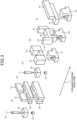
- FIGS. 3(a) to 3(f) are schematic diagrams illustrating a structure example of the evaluation dies 10.
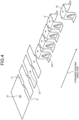
- FIG. 4 is a diagram illustrating the shape of the coil material S press-formed by the evaluation dies 10 illustrated in FIG. 3 .
- the evaluation dies 10 includes dies for performing six press-forming steps, namely, dies for a first piercing step, a blanking step, a second piercing step, a bending step, a flange trimming step, and a separate trimming step in order from the forward feeding direction of the coil material S.
- the dies are arranged side by side along a straight line and are collected in the evaluation dies 10.
- the dies include upper blades such as a piercing punch 11, blanking upper blades 12, bending blades 13, and trimming upper blades 14, lower blades such as a button die 15, a blanking lower blade 16, a punch 17, and a trimming lower blade 18, and sheet holders 19.
- upper blades such as a piercing punch 11, blanking upper blades 12, bending blades 13, and trimming upper blades 14, lower blades such as a button die 15, a blanking lower blade 16, a punch 17, and a trimming lower blade 18, and sheet holders 19.
- the sheet holders 19 may be made of, for example, general carbon steel such as S45C. Furthermore, in FIGS. 3(a) to 3(f) , the sheet holders 19 of the dies are illustrated separately, however, the sheet holders 19 of the respective dies may be manufactured as an integral body connected in the evaluation dies 10. In addition, since a large force is applied to the upper blades and the lower blades during press-forming, the upper blades and the lower blades are evaluation targets for occurrence of a die damage. Therefore, each die steel material has a replaceable structure and can be fixed to the main body of the evaluation dies 10, which are manufactured by casting or the like, with a bolt or the like.
- die steel materials can be replaced, as desired for the purpose of evaluation, with, for example, SKD11 of cold die steel or SKH51 of high-speed steel.
- coating treatment of the die steel material it is possible to evaluate the die damage behavior by not performing the coating treatment on each die steel material or performing a desired coating treatment such as PVD coating.
- an example as a replaceable structure of the die steel material is a structure that enables replacement in such a manner that the shear clearance of dies as a shearing means is always made constant by a positioning component such as a knock pin.
- the material and the surface coating of the dies in each of the press-forming steps are not necessarily the same.
- the dies have bilaterally symmetrical shapes, a combination of die materials and surface coatings that are different on the right and the left may be used in order to enhance the evaluation efficiency.
- piercing processing for forming a hole 20 (see FIG. 4 ) in the coil material S is performed using the piercing punch 11.
- the hole 20 formed by the dies illustrated in FIG. 3(a) is preferably formed so as to insert a pilot pin for positioning the coil material S in a subsequent step, formation of the hole 20 by the dies illustrated in FIG. 3(c) is optional.
- an outer peripheral portion 21 (see FIG. 4 ) of a cross-section-hat-shaped component 30 is sheared in a U shape from the coil material S using the blanking upper blades 12 and the blanking lower blade 16.
- the length and the shape of the coil material S to be sheared may be determined depending on the shape of the cross-section-hat-shaped component 30 to be press-formed.
- the corner portions sheared in the U shape may have a right angle or may have a rounded shape.
- the coil material S is press-formed into a hat-shaped cross-sectional shape having a top portion face 30a and vertical wall portions 30b and flange portions 30c continuous with the top portion face 30a using the bending blades 13.
- the vertical wall portions 30b and the flange portions 30c are press-formed by the bending blades 13.
- the hat-shaped cross-sectional shape can be determined as desired.
- the angle formed by the top portion face 30a and a vertical wall portion 30b is usually about 90 to 150 degrees, and a die damage is more likely to occur as the angle is closer to 90 degrees.
- bending may be performed at a bending angle less than or equal to 90 degrees using a cam mechanism or the like.
- a vertical wall portion 30b includes a joggle shape 30d (see FIGS. 2 and 4 ).
- a joggle shape 30d By forming the joggle shape portion through bending, a very high contact surface pressure is generated in the bending blades 13, and thus a die damage is likely to occur.
- the joggle shape 30d may have any shape and may be a triangular shape or a rectangular shape. The closer the joggle shape 30d is to a rectangular shape, the more likely the die is damaged.
- the projecting height of the joggle shape 30d may be set as desired. A die damage is more likely to occur as the projecting height is higher.
- a trimming upper blade 14 may shear a flange portion 30c simultaneously in the width direction, or as illustrated in FIG.
- a trimming upper blade 14 may have a shearing angle ⁇ 1 to have different timing for shearing a flange portion 30c in the width direction. Furthermore, as illustrated in FIG. 6(a) , the flange portion 30c may be sheared in parallel to the pressing direction, or as illustrated in FIG. 6(b) , the flange portion 30c may be sheared at a predetermined shear angle ⁇ 2 using a cam mechanism or the like. As described above, the flange trimming step can be designed as desired depending on a presumed mass production pressing step.
- the coil material S is connected until the press-forming step before the separate trimming step, and one cross-section-hat-shaped component 30 is separated from the connected coil material S in the separate trimming step by the trimming upper blades 14 illustrated in FIG. 3(f) .
- the coil material S may be cut horizontally by linearly shearing the coil material S at a connecting portion with a cross-section-hat-shaped component 30 that follows, or as illustrated in FIG. 7(b) , the top portion face 30a, the vertical wall portions 30b, and the flange portions 30c may be cut vertically by shearing at a time.
- a die damage is more likely to occur in vertical cutting than in flat cutting.
- continuous press-forming is performed using the damage evaluation device 1 for a press-forming die according to the embodiment of the invention.
- the time required for 1000 times of press-forming is about 50 minutes, and it is possible to perform many times of press-forming in a short time as compared with the sliding test or the press-forming test which are evaluation methods of die damages.
- the press-forming may be performed without stopping up to a target number of times of press-forming, or the press-forming may be stopped at predetermined number of times of press-forming such as 100 times, 1000 times, 2000 times, or 5000 times, and the evaluation dies 10 may be taken out to observe the damage behavior of the die steel material in each of the press-forming steps.
- the observation method by the observation device 100 may be determined as desired depending on the evaluation purpose such as appearance observation by photographing, detailed observation by a portable small microscope, or investigation of the wear amount by imitating the die shape with a cured resin.
- the quality of the die steel material and the effectiveness of the surface coating may be evaluated by changing at least two or more conditions such as the quality of the die steel material, the presence or absence of the surface coating, or the type of the surface coating and comparing the damage behavior before and after the change.
- a cross-section-hat-shaped component formed by the evaluation dies was set to have a width of the top portion face of 50 mm, a height of the vertical walls of 50 mm, a length of the flanges of 30 mm, and a vertical length in the cross-section of 50 mm, and the boundaries between the top portion face and the vertical wall portions and between the vertical wall portions and the flanges have a bending radius of 10 mm.
- the top portion face was provided with connecting portions of 10 mm each for connecting with preceding and following cross-section-hat-shaped components.
- a triangular joggle shape having a length of the base of 40 mm, a height of 40 mm, and a projecting height of 5 mm was formed on one of the vertical wall portions of the cross-section-hat-shaped component.
- the bending radius of the joggle shape was set to 5 mm.
- the other vertical wall portion was not formed with the joggle shape.
- the angles formed by the top portion face and the vertical wall portions and the angles formed by the vertical wall portions and the flange portions were both set to 90 degrees.
- the target coil material was a non-plated high-tensile steel sheet having tensile strengths of 1470 MPa and 980 MPa, and the sheet thickness was set to 1.4 mm.
- the width of the coil material was set to 200 mm on the basis of the hat-shaped cross-sectional shape to be formed.
- Evaluation dies were set to have six press-forming steps of a first piercing step, a blanking step, a second piercing step, a bending step, a flange trimming step, and a separate trimming step in order from the forward feeding direction of the coil material.
- a round hole having a diameter of 12 mm was punched out at the center of a connecting portion of a cross-section-hat-shaped component so that a pilot pin for positioning in a subsequent step can be inserted.
- the second piercing step a round hole having a diameter of 7 mm was punched out at the center of a top portion face of the cross-section-hat-shaped component.
- the gap (clearance) between a piercing punch and a button die was set to 12.5% of the sheet thickness of the coil material.
- U-shaped outer peripheral portions having a length of 85 mm and a width of 20 mm were sheared symmetrically with respect to the center of the coil material.
- the corners were set to have a rounded shape with a radius of 10 mm.
- the gap (clearance) between a blanking blade and a lower blade was set to 12.5% of the sheet thickness of the coil material.
- the top portion face was held with a sheet holder, and then the cross-section-hat-shaped component was formed with the bending blades.
- the sheet holding force was set to 5 tons.
- the cross-section-hat-shaped component was held with a sheet holder, and then flange portions on both sides were sheared by about 4 mm from the flange ends.
- the sheet holding force was set to 5 tons.
- the shearing angle and the shear angle were set to 0 degrees.
- the gap between a trimming blade and a lower blade was set to 12.5% of the sheet thickness of the coil material.
- the separate trimming step was set to linearly shear the center of a connecting portion of the cross-section-hat-shaped component.
- the gap between a trimming blade and a lower blade was set to 12.5% of the sheet thickness of the coil material.
- Table 1 shows combinations of a coil material and die steel materials and a coating treatment in the six press-forming steps when a continuous press test was performed with the evaluation dies.
- a continuous press test was performed using the above evaluation dies.
- a pressing device used was a mechanical pressing device with a pressing capability of 250 tons, and continuous press-forming was performed at a forming speed of 30 spm.
- the coil material was loaded to the evaluation dies at a pitch of 70 mm by an uncoiler leveler.
- As for lubrication of the coil material rustproof oil at the time of receiving the coil was used as it is.
- the continuous press test was performed, and after the number of times of pressing reached 100, 1000, 2000, 5000, 8000, and 10000 times, the evaluation dies was taken out from the pressing device, and the damage behavior of the die steel material was observed.
- Tables 2 to 8 The damage behavior of the die steel material at the time of each observation is shown in Tables 2 to 8.
- Table 2 shows the damage behavior of the die steel material in the first piercing step
- Table 3 shows the damage behavior of the die steel material in the blanking step
- Table 4 shows the damage behavior of the die steel material in the third piercing step
- Tables 5 and 6 show the damage behavior of the die steel material with and without the joggle shape in the bending step
- Tables 7 and 8 show the damage behavior of the die steel material with and without the joggle shape in the flange trimming step.
- the die was damaged earlier in the bending blade with the joggle shape than the bending blade without the joggle shape. This is because the contact surface pressure between the material and the die at the time of forming is higher in the case where there is a joggle shape and that the surface coating and the die steel material are more likely to be damaged.
- the die was damaged earlier in the trimming blade on the side without the joggle shape than in the trimming blade on the side with the joggle shape. Since no shape is formed on the side without the joggle shape and the rigidity of the vertical wall is low, spring back of the cross section is larger than that on the side with the joggle shape.
- a damage evaluation device and a damage evaluation method for a press-forming die that are capable of quantitatively evaluating a die damage for predetermined die steel material and coating treatment.
Landscapes
- Engineering & Computer Science (AREA)
- Mechanical Engineering (AREA)
- Physics & Mathematics (AREA)
- General Physics & Mathematics (AREA)
- Chemical & Material Sciences (AREA)
- Materials Engineering (AREA)
- Mounting, Exchange, And Manufacturing Of Dies (AREA)
- Shaping Metal By Deep-Drawing, Or The Like (AREA)
Abstract
Description
- The present invention relates to a damage evaluation device and a damage evaluation method for a press-forming die.
- In recent years, a high-tensile steel sheet having high strength has been applied to vehicle body frame components of vehicles from the viewpoint of weight reduction of the vehicle body and improvement of the collision safety. In general, vehicle body frame components are mass-produced by press-forming using dies. However, since high-tensile steel sheets have poor ductility and high strength, cracks, wrinkles, or spring back (poor dimensional accuracy) is remarkably generated by press-forming. Therefore, it is necessary to take measures against such forming defects. When a high-tensile steel sheet is press-formed, not only forming defects as described above but also a die damage is one of major problems.
- In general, in a case where the strength of a material increases, a load required for shearing for cutting the material increases, and in press-forming using a die, a contact surface pressure to the die increases. Therefore, chipping or wear of the dies steel material, seizure of the material, or the like is likely to occur. In addition, if press-forming is continued in a state where the die is damaged, not only the appearance of the press-formed product is impaired, but also the quality of the sheared surface is deteriorated, which may greatly affect the formability in a next press-forming step, hydrogen embrittlement resistance after the product is formed, or the like. From such a background, measures against die damages such as chipping, wear, and seizure of a die steel material or a surface coating film are proposed.
- Specifically, Patent Literature 1 describes a method of applying a coating treatment by a physical vapor deposition (PVD) method to a formed surface in contact with a steel sheet in order to prevent seizure during press-forming. Moreover,
Patent Literatures Patent Literature 4 describes a method of evaluating die galling properties by sandwiching a band-shaped steel sheet by steel blocks facing to each other, drawing out the steel sheet in this state, and then observing a surface or the like of the steel blocks. In addition,Patent Literature 5 describes evaluation dies for evaluating die galling properties by performing press-forming with dies including a punch having three or more recessed parts on the outer periphery as viewed in parallel to a pressing direction and a fitting part into which a punch relatively moved in the pressing direction is fitted with a predetermined clearance. -
- Patent Literature 1:
JP 5135479 B2 - Patent Literature 2:
JP 2011-189419 A - Patent Literature 3:
JP 4737606 B2 - Patent Literature 4:
JP 4677804 B2 - Patent Literature 5:
JP 2010-167437 A - As described in Patent Literatures 1 to 3, it is effective to adopt a die steel material having excellent durability or to perform a coating treatment as a countermeasure against die damages. However, in recent years, steel materials for dies and a coating treatment are provided from various manufacturers, and it is difficult to select which die steel material and coating treatment are effective. Meanwhile, the number of times of a sliding test or a press-forming test performed in the methods described in
Patent Literatures - The present invention has been made in view of the above problems, and an object of the invention is to provide a damage evaluation device and a damage evaluation method for a press-forming die that are capable of quantitatively evaluating a die damage for predetermined die steel material and coating treatment.
- A damage evaluation device for a press-forming die according to the present invention includes: evaluation dies installed in a pressing device configured to press-form a metal material; and an observation device configured to observe damage behavior of a die steel material and surface coating constituting the evaluation dies, wherein the evaluation dies include: a perforating unit configured to form a hole in the metal material; a first shearing unit configured to shear the metal material in which the hole is formed into a predetermined metal component shape; and a second shearing unit configured to separate a metal component from the metal material, and dies of the perforating unit, the first shearing unit and the second shearing unit are formed of the die steel material and have a structure that enables replacement with another die made of predetermined material and applied with predetermined surface coating treatment.
- The evaluation dies may include: a press-forming unit configured to press-form the metal material after shearing by the first shearing unit into a shape having a hat-shaped cross-section, the shape having a top portion face, vertical wall portions continuous with the top portion face, and flange portions continuous with the vertical wall portions; and a third shearing unit configured to shear a part of the flange portions, dies of the press-forming unit and the third shearing unit may be formed of the die steel material and have a structure that enables replacement with another die made of predetermined material and applied with predetermined surface coating treatment, and the second shearing unit may be configured to separate a metal component having the shape having the hat-shaped cross-section from the metal material after shearing by the third shearing unit.
- The shape having the hat-shaped cross-section may have a protruding shape on one of the vertical wall portions.
- A damage evaluation method for a press-forming die according to the present invention includes: a step of observing damage behavior of a die steel material and surface coating constituting evaluation dies after press-forming is repeated on a metal material for predetermined number of times using the evaluation dies installed in a pressing device, wherein the evaluation dies include: a perforating unit configured to form a hole in the metal material; a first shearing unit configured to shear the metal material in which the hole is formed into a predetermined metal component shape; and a second shearing unit configured to separate a metal component from the metal material, and dies of the perforating unit, the first shearing unit and the second shearing unit are formed of the die steel material and have a structure that enables replacement with another die made of predetermined material and applied with predetermined surface coating treatment.
- The evaluation dies may include: a press-forming unit configured to press-form the metal material after shearing by the first shearing unit into a shape having a hat-shaped cross-section, the shape having a top portion face, vertical wall portions continuous with the top portion face, and flange portions continuous with the vertical wall portions; and a third shearing unit configured to shear a part of the flange portions, dies of the press-forming unit and the third shearing unit may be formed of the die steel material and have a structure that enables replacement with another die made of predetermined material and applied with predetermined surface coating treatment, and the second shearing unit may be configured to separate a metal component having the shape having the hat-shaped cross-section from the metal material after shearing by the third shearing unit.
- The shape having the hat-shaped cross-section may have a protruding shape on one of the vertical wall portions.
- According to a damage evaluation device and a damage evaluation method for a press-forming die according to the present invention, it is possible to quantitatively evaluate a die damage for predetermined die steel material and coating treatment.
-
-
FIG. 1 is a schematic diagram illustrating an overall structure of a damage evaluation device for a press-forming die according to an embodiment of the present invention. -
FIG. 2 is a diagram illustrating the structure of a cross-section-hat-shaped component. -
FIG. 3 is a schematic diagram illustrating a structure example of an evaluation die. -
FIG. 4 is a diagram illustrating the shape of a coil material press-formed by the evaluation dies illustrated inFIG. 3 . -
FIG. 5 is a diagram for explaining a flange trimming step. -
FIG. 6 is a diagram for explaining the flange trimming step. -
FIG. 7 is a diagram for explaining a separate trimming step. - Hereinafter, a damage evaluation device and a damage evaluation method for a press-forming die according to an embodiment of the present invention will be described with reference to the drawings.
- First, the overall structure of the damage evaluation device for a press-forming die according to the embodiment of the invention will be described with reference to
FIG. 1 . -
FIG. 1 is a schematic diagram illustrating the overall structure of the damage evaluation device for a press-forming die according to the embodiment of the invention. As illustrated inFIG. 1 , a damage evaluation device 1 for a press-forming die according to the embodiment of the invention includes a pay-off reel 2, anuncoiler leveler 3, apressing device 4, aconveyance device 5, a scrap bag 6, and anobservation device 100. In the damage evaluation device 1 for a press-forming die as the embodiment of the invention, a coiled metal material (hereinafter, referred to as a coil material) S (mainly a high-tensile steel sheet) to be press-formed is set in the pay-off reel 2, and, first, the coil material S that is unwound is supplied to theuncoiler leveler 3. Next, the coil material S that has been straightened by theuncoiler leveler 3 is sent to the inside of evaluation dies 10 attached to thepressing device 4. Next, after the coil material S is press-formed using the evaluation dies 10, the coil material S is fed in the forward feeding direction by a predetermined pitch, and similar press-forming is repeated. Next, although the coil material S sent to the inside of theevaluation dies 10 is continuous, the coil material S is separated into component units in the final step of theevaluation dies 10, carried out to the outside of thepressing device 4 by theconveyance device 5, and then sent to the scrap bag 6 or the like. Then, the damage behavior of the die steel material and the surface coating constituting theevaluation dies 10 is observed using theobservation device 100. - Next, the structure of the
evaluation dies 10 will be described with reference toFIGS. 2 to 7 . Note that, in the following description, evaluation dies for continuously press-forming a cross-section-hat-shaped component 30 as illustrated inFIGS. 2(a) to 2(c) will be described as an example. As illustrated inFIGS. 2(a) to 2(c) , the cross-section-hat-shaped component 30 includes atop portion face 30a,vertical wall portions 30b andflange portions 30c continuously formed from thetop portion face 30a, and ajoggle shape 30d formed on one of thevertical wall portions 30b. When the cross-section-hat-shaped component 30 is press-formed, a high-tensile steel sheet having a tensile strength higher than or equal to 980 MPa in which a die damage significantly occurs is basically used as the coil material S, however, any material may be used. In addition, the width of the coil material S is, for example, about 200 mm in a case where the width of the top portion face is 50 mm, the height of the vertical wall is 50 mm, and the length of the flange is about 30 mm and may be determined from the size of the component to be press-formed. Moreover, the surface of the coil material S may be either a non-plated material or a plated material. In the case of a non-plated material, it is possible to evaluate the behavior of a die damage caused by seizure of the material to the die by press-forming. Meanwhile, in the case of a plated material, a hot-dip galvanized steel sheet, a hot-dip galvannealed steel sheet, an electrogalvanized steel sheet, or the like can be used for evaluation, and plating adhesion behavior or the like to a die can be evaluated for each type of plating. -
FIGS. 3(a) to 3(f) are schematic diagrams illustrating a structure example of the evaluation dies 10.FIG. 4 is a diagram illustrating the shape of the coil material S press-formed by the evaluation dies 10 illustrated inFIG. 3 . As illustrated inFIGS. 3(a) to 3(f) , the evaluation dies 10 includes dies for performing six press-forming steps, namely, dies for a first piercing step, a blanking step, a second piercing step, a bending step, a flange trimming step, and a separate trimming step in order from the forward feeding direction of the coil material S. The dies are arranged side by side along a straight line and are collected in the evaluation dies 10. The dies include upper blades such as a piercingpunch 11, blankingupper blades 12, bendingblades 13, and trimmingupper blades 14, lower blades such as abutton die 15, a blankinglower blade 16, apunch 17, and a trimminglower blade 18, andsheet holders 19. - Since no large force is applied to the
sheet holders 19 during press-forming, thesheet holders 19 may be made of, for example, general carbon steel such as S45C. Furthermore, inFIGS. 3(a) to 3(f) , thesheet holders 19 of the dies are illustrated separately, however, thesheet holders 19 of the respective dies may be manufactured as an integral body connected in the evaluation dies 10. In addition, since a large force is applied to the upper blades and the lower blades during press-forming, the upper blades and the lower blades are evaluation targets for occurrence of a die damage. Therefore, each die steel material has a replaceable structure and can be fixed to the main body of the evaluation dies 10, which are manufactured by casting or the like, with a bolt or the like. These die steel materials can be replaced, as desired for the purpose of evaluation, with, for example, SKD11 of cold die steel or SKH51 of high-speed steel. In addition, regarding the coating treatment of the die steel material, it is possible to evaluate the die damage behavior by not performing the coating treatment on each die steel material or performing a desired coating treatment such as PVD coating. - Note that, an example as a replaceable structure of the die steel material is a structure that enables replacement in such a manner that the shear clearance of dies as a shearing means is always made constant by a positioning component such as a knock pin. Incidentally, the material and the surface coating of the dies in each of the press-forming steps are not necessarily the same. In addition, if the dies have bilaterally symmetrical shapes, a combination of die materials and surface coatings that are different on the right and the left may be used in order to enhance the evaluation efficiency.
- Hereinafter, each of the press-forming steps will be described.
- As illustrated in
FIGS. 3(a) and 3(c) , in the first and second piercing steps, piercing processing for forming a hole 20 (seeFIG. 4 ) in the coil material S is performed using the piercingpunch 11. However, although thehole 20 formed by the dies illustrated inFIG. 3(a) is preferably formed so as to insert a pilot pin for positioning the coil material S in a subsequent step, formation of thehole 20 by the dies illustrated inFIG. 3(c) is optional. - As illustrated in
FIG. 3(b) , in the blanking step, an outer peripheral portion 21 (seeFIG. 4 ) of a cross-section-hat-shapedcomponent 30 is sheared in a U shape from the coil material S using the blankingupper blades 12 and the blankinglower blade 16. The length and the shape of the coil material S to be sheared may be determined depending on the shape of the cross-section-hat-shapedcomponent 30 to be press-formed. Incidentally, the corner portions sheared in the U shape may have a right angle or may have a rounded shape. - As illustrated in
FIG. 3(d) , in the bending step, the coil material S is press-formed into a hat-shaped cross-sectional shape having atop portion face 30a andvertical wall portions 30b andflange portions 30c continuous with thetop portion face 30a using thebending blades 13. Specifically, after the top portion face portion of the coil material S is held by thesheet holder 19, thevertical wall portions 30b and theflange portions 30c are press-formed by thebending blades 13. Note that the hat-shaped cross-sectional shape can be determined as desired. For example, the angle formed by thetop portion face 30a and avertical wall portion 30b is usually about 90 to 150 degrees, and a die damage is more likely to occur as the angle is closer to 90 degrees. In addition, bending may be performed at a bending angle less than or equal to 90 degrees using a cam mechanism or the like. - In the present embodiment, a
vertical wall portion 30b includes ajoggle shape 30d (seeFIGS. 2 and4 ). By forming the joggle shape portion through bending, a very high contact surface pressure is generated in thebending blades 13, and thus a die damage is likely to occur. As illustrated inFIGS. 2(a) to 2(c) , by forming thejoggle shape 30d only in one of thevertical wall portions 30b, the difference in the occurrence behavior of a die damage due to the presence or absence of the joggle shape can be evaluated by one time of press-forming. In addition, thejoggle shape 30d may have any shape and may be a triangular shape or a rectangular shape. The closer thejoggle shape 30d is to a rectangular shape, the more likely the die is damaged. Furthermore, the projecting height of thejoggle shape 30d may be set as desired. A die damage is more likely to occur as the projecting height is higher. - As illustrated in
FIG. 3(e) , in the flange trimming step, parts of theflange portions 30c of the cross-section-hat-shapedcomponent 30 press-formed by the bending step are sheared by the trimmingupper blades 14. Specifically, after the cross-section-hat-shapedcomponent 30 is held by thesheet holder 19 having the same shape as that of the cross-section-hat-shapedcomponent 30, theflange portions 30c protruding from thesheet holder 19 are sheared by the trimmingupper blades 14. As illustrated inFIG. 5(a) , a trimmingupper blade 14 may shear aflange portion 30c simultaneously in the width direction, or as illustrated inFIG. 5(b) , a trimmingupper blade 14 may have a shearing angle θ1 to have different timing for shearing aflange portion 30c in the width direction. Furthermore, as illustrated inFIG. 6(a) , theflange portion 30c may be sheared in parallel to the pressing direction, or as illustrated inFIG. 6(b) , theflange portion 30c may be sheared at a predetermined shear angle θ2 using a cam mechanism or the like. As described above, the flange trimming step can be designed as desired depending on a presumed mass production pressing step. - As illustrated in
FIG. 4 , the coil material S is connected until the press-forming step before the separate trimming step, and one cross-section-hat-shapedcomponent 30 is separated from the connected coil material S in the separate trimming step by the trimmingupper blades 14 illustrated inFIG. 3(f) . Note that, in the separate trimming step, as illustrated inFIG. 7(a) , the coil material S may be cut horizontally by linearly shearing the coil material S at a connecting portion with a cross-section-hat-shapedcomponent 30 that follows, or as illustrated inFIG. 7(b) , thetop portion face 30a, thevertical wall portions 30b, and theflange portions 30c may be cut vertically by shearing at a time. In general, a die damage is more likely to occur in vertical cutting than in flat cutting. - Next, a damage evaluation method for a press-forming die according to an embodiment of the invention will be described.
- In the damage evaluation method for a press-forming die according to the embodiment of the invention, continuous press-forming is performed using the damage evaluation device 1 for a press-forming die according to the embodiment of the invention. Although it depends on the specifications of a pressing device to be used, for example, in a case where continuous press-forming is performed at 20 shots per minute (spm) in which press-forming is performed 20 times per minute, the time required for 1000 times of press-forming is about 50 minutes, and it is possible to perform many times of press-forming in a short time as compared with the sliding test or the press-forming test which are evaluation methods of die damages.
- During the continuous press-forming, the press-forming may be performed without stopping up to a target number of times of press-forming, or the press-forming may be stopped at predetermined number of times of press-forming such as 100 times, 1000 times, 2000 times, or 5000 times, and the evaluation dies 10 may be taken out to observe the damage behavior of the die steel material in each of the press-forming steps. The observation method by the
observation device 100 may be determined as desired depending on the evaluation purpose such as appearance observation by photographing, detailed observation by a portable small microscope, or investigation of the wear amount by imitating the die shape with a cured resin. - Note that, in addition to the observation of the damage behavior of the die steel material depending on the number of times of press-forming, the quality of the die steel material and the effectiveness of the surface coating may be evaluated by changing at least two or more conditions such as the quality of the die steel material, the presence or absence of the surface coating, or the type of the surface coating and comparing the damage behavior before and after the change.
- In the present example, a cross-section-hat-shaped component formed by the evaluation dies was set to have a width of the top portion face of 50 mm, a height of the vertical walls of 50 mm, a length of the flanges of 30 mm, and a vertical length in the cross-section of 50 mm, and the boundaries between the top portion face and the vertical wall portions and between the vertical wall portions and the flanges have a bending radius of 10 mm. The top portion face was provided with connecting portions of 10 mm each for connecting with preceding and following cross-section-hat-shaped components. A triangular joggle shape having a length of the base of 40 mm, a height of 40 mm, and a projecting height of 5 mm was formed on one of the vertical wall portions of the cross-section-hat-shaped component. The bending radius of the joggle shape was set to 5 mm. The other vertical wall portion was not formed with the joggle shape. The angles formed by the top portion face and the vertical wall portions and the angles formed by the vertical wall portions and the flange portions were both set to 90 degrees. The target coil material was a non-plated high-tensile steel sheet having tensile strengths of 1470 MPa and 980 MPa, and the sheet thickness was set to 1.4 mm. The width of the coil material was set to 200 mm on the basis of the hat-shaped cross-sectional shape to be formed.
- Evaluation dies were set to have six press-forming steps of a first piercing step, a blanking step, a second piercing step, a bending step, a flange trimming step, and a separate trimming step in order from the forward feeding direction of the coil material. In the first piercing step, a round hole having a diameter of 12 mm was punched out at the center of a connecting portion of a cross-section-hat-shaped component so that a pilot pin for positioning in a subsequent step can be inserted. In the second piercing step, a round hole having a diameter of 7 mm was punched out at the center of a top portion face of the cross-section-hat-shaped component. In the first and second piercing steps, the gap (clearance) between a piercing punch and a button die was set to 12.5% of the sheet thickness of the coil material.
- In the blanking step, U-shaped outer peripheral portions having a length of 85 mm and a width of 20 mm were sheared symmetrically with respect to the center of the coil material. The corners were set to have a rounded shape with a radius of 10 mm. The gap (clearance) between a blanking blade and a lower blade was set to 12.5% of the sheet thickness of the coil material. In the bending step, the top portion face was held with a sheet holder, and then the cross-section-hat-shaped component was formed with the bending blades. The sheet holding force was set to 5 tons. In the flange trimming step, the cross-section-hat-shaped component was held with a sheet holder, and then flange portions on both sides were sheared by about 4 mm from the flange ends. The sheet holding force was set to 5 tons. The shearing angle and the shear angle were set to 0 degrees. The gap between a trimming blade and a lower blade was set to 12.5% of the sheet thickness of the coil material. The separate trimming step was set to linearly shear the center of a connecting portion of the cross-section-hat-shaped component. The gap between a trimming blade and a lower blade was set to 12.5% of the sheet thickness of the coil material.
- Table 1 shows combinations of a coil material and die steel materials and a coating treatment in the six press-forming steps when a continuous press test was performed with the evaluation dies. By comparing the continuous press conditions of No. 1 and No. 2, it is possible to investigate the influence of the difference in the die steel material on the die damage behavior. By comparing the continuous press conditions of No. 1 and No. 3, it is possible to investigate the influence of the difference in the material strength of the coil material on the die damage. It is possible to investigate the influence of the presence or absence of surface coating on the die damage by comparing the continuous press conditions of No. 1 and No. 5 or No. 2 and No. 4. By comparing the continuous press conditions of No. 5 and No. 6, it is possible to investigate the influence of the difference in the type of the surface coating on the die damage. Note that, for the die steel material in the bending step, in the case of no surface coating, seizure of the coil material occurs in several times of press-forming, and therefore, the surface coating treatment was performed for all the continuous press conditions.
Table 1 No. Coil Material Piercing Step Blanking Step Piercing Step Bending Step Flange Trimming Step Separate Trimming Step Piercing Punch Button Die Blanking Blade Lower Blade Piercing Punch Button Die Bending Blade Punch Trimming Blade Lower Blade Trimming Blade Lower Blade 1 1470 Mpa Steel Material A No Coating Steel Material B No Coating Steel Material A No Coating Steel Material A No Coating Steel Material A No Coating Steel Material B No Coating Steel Material A Coating A Steel Material A No Coating Steel Material A No Coating Steel Material A No Coating Steel Material A No Coating Steel Material A No Coating 2 1470 Mpa Steel Material B No Coating Steel Material B No Coating Steel Material B No Coating Steel Material A No Coating Steel Material B No Coating Steel Material B No Coating Steel Material B Coating A Steel Material A No Coating Steel Material B No Coating Steel Material A No Coating Steel Material B No Coating Steel Material A No Coating 3 980 Mpa Steel Material A No Coating Steel Material B No Coating Steel Material A No Coating Steel Material A No Coating Steel Material A No Coating Steel Material B No Coating Steel Material A Coating A Steel Material A No Coating Steel Material A No Coating Steel Material A No Coating Steel Material A No Coating Steel Material A No Coating 4 1470 Mpa Steel Material B Coating A Steel Material B No Coating Steel Material B Coating A Steel Material A No Coating Steel Material B Coating A Steel Material B No Coating Steel Material B Coating A Steel Material A No Coating Steel Material B Coating A Steel Material A No Coating Steel Material B Coating A Steel Material A No Coating 5 1470 Mpa Steel Material A Coating A Steel Material B No Coating Steel Material A Coating A Steel Material A No Coating Steel Material A Coating A Steel Material B No Coating Steel Material A Coating A Steel Material A No Coating Steel Material A Coating A Steel Material A No Coating Steel Material A Coating A Steel Material A No Coating 6 1470 Mpa Steel Material A Coating B Steel Material B No Coating Steel Material A Coating B Steel Material A No Coating Steel Material A Coating B Steel Material B No Coating Steel Material A Coating B Steel Material A No Coating Steel Material A Coating B Steel Material A No Coating Steel Material A Coating B Steel Material A No Coating - A continuous press test was performed using the above evaluation dies. A pressing device used was a mechanical pressing device with a pressing capability of 250 tons, and continuous press-forming was performed at a forming speed of 30 spm. After one time of press-forming, the coil material was loaded to the evaluation dies at a pitch of 70 mm by an uncoiler leveler. As for lubrication of the coil material, rustproof oil at the time of receiving the coil was used as it is. The continuous press test was performed, and after the number of times of pressing reached 100, 1000, 2000, 5000, 8000, and 10000 times, the evaluation dies was taken out from the pressing device, and the damage behavior of the die steel material was observed. The damage behavior of the die steel material at the time of each observation is shown in Tables 2 to 8. Table 2 shows the damage behavior of the die steel material in the first piercing step, Table 3 shows the damage behavior of the die steel material in the blanking step, Table 4 shows the damage behavior of the die steel material in the third piercing step, Tables 5 and 6 show the damage behavior of the die steel material with and without the joggle shape in the bending step, and Tables 7 and 8 show the damage behavior of the die steel material with and without the joggle shape in the flange trimming step. A case where there was almost no damage was evaluated as "good", a case where the length of a damage was a minute damage of less than 1 mm was evaluated as "fair", and a case where the length of a damage was a large damage greater than or equal to 1 mm was evaluated as "bad".
Table 2 No. Coil Material Die Steel Material Number of Times of Press-Forming Steel Material Coating 100 1,000 2,000 5,000 8,000 10,000 1 1470 A No Coating good good good bad bad bad 2 1470 B No Coating good good good fair fair bad 3 980 A No Coating good good good good good good 4 1470 B A good good good good good good 5 1470 A A good good good bad bad bad 6 1470 A B good good bad bad bad bad Table 3 No. Coil Material Die Steel Material Number of Times of Press-Forming Steel Material Coating 100 1,000 2,000 5,000 8,000 10,000 1 1470 A No Coating good fair fair bad bad bad 2 1470 B No Coatinq good good good good bad bad 3 980 A No Coating good good good good fair fair 4 1470 B A good good good good fair fair 5 1470 A A good fair fair bad bad 6 1470 A B good fair bad bad bad Table 4 No. Coil Material Die Steel Material Number of Times of Press-Forming Steel Material Coating 100 1,000 2,000 5,000 8,000 10,000 1 1470 A No Coating good good good bad bad bad 2 1470 B No Coating good good good good good good 3 980 A No Coating good good good good good bad 4 1470 B A good good good good good good 5 1470 A A good good good good good good 6 1470 A B good good good bad bad bad Table 5 No. Coil Material Die Steel Material Number of Times of Press-Forming Steel Material Coating 100 1,000 2,000 5,000 8,000 10,000 1 1470 A A good good good bad bad bad 2 1470 B A good good good good good good 3 980 A A good good good fair bad bad 4 1470 B A good good good good good good 5 1470 A A good good good bad bad bad 6 1470 A B good good bad bad bad bad Table 6 No. Coil Material Die Steel Material Number of Times of Press-Forming Steel Material Coating 100 1,000 2,000 5,000 8,000 10,000 1 1470 A A good good good good good good 2 1470 B A good good good good good good 3 980 A A good good good good good good 4 1470 B A good good good good good good 5 1470 A A good good good good good good 6 1470 A B good good good bad bad bad Table 7 No. Coil Material Die Steel Material Number of Times of Press-Forming Steel Material Coating 100 1,000 2,000 5,000 8,000 10,000 1 1470 A No Coating good good good good good bad 2 1470 B No Coating good good good good good good 3 980 A No Coating good good good good good bad 4 1470 B A good good good good good good 5 1470 A A good good good good good bad 6 1470 A B good good good good bad bad Table 8 No. Coil Material Die Steel Material Number of Times of Press-Forming Steel Material Coating 100 1,000 2,000 5,000 8,000 10,000 1 1470 A No Coating good fair bad bad bad bad 2 1470 B No Coating good good good fair bad bad 3 980 A No Coating good good good fair bad bad 4 1470 B A good good good fair fair fair 5 1470 A A good fair fair bad bad bad 6 1470 A B good fair bad bad bad bad - From the above results, it was confirmed that die damage in each press-forming step can be quantitatively evaluated with the number of times of press-forming equivalent to that of mass production pressing. By the continuous press test in which the combination of the die steel material and the surface coating in the press-forming steps was changed, it was also confirmed that a die damage occurs earlier as the material strength of the coil material is higher. Furthermore, it was also confirmed that the die steel material B is superior in durability to the die steel material A and that damages are less likely to occur in a case where surface coating treatment is performed. It was further confirmed that, in a case of the same coil material and the same die steel material, the surface coating A is superior in durability to the surface coating B. Focusing on the forming conditions, the die was damaged earlier in the bending blade with the joggle shape than the bending blade without the joggle shape. This is because the contact surface pressure between the material and the die at the time of forming is higher in the case where there is a joggle shape and that the surface coating and the die steel material are more likely to be damaged. In addition, focusing on the shearing conditions, in the flange trimming step, the die was damaged earlier in the trimming blade on the side without the joggle shape than in the trimming blade on the side with the joggle shape. Since no shape is formed on the side without the joggle shape and the rigidity of the vertical wall is low, spring back of the cross section is larger than that on the side with the joggle shape. This is because holding of the sheet at the time of flange trimming is not sufficient, and shearing is unstable such as that the flange ends are displaced. As a result, it has been confirmed that, according to the present invention, it is possible to quantitatively evaluate die damages generated in mass production press-forming of automobile body frame parts and the like to which a high-tensile steel sheet is applied, for predetermined die steel material and surface coating treatment and to provide selection criteria for die steel material and surface coating treatment to be used in mass production press-forming.
- Although the embodiments applied with the invention made by the present inventors have been described above, the present invention is not limited by the description and the drawings included as a part of the disclosure of the present invention according to the embodiments. That is, other embodiments, examples, operation technology, and the like implemented by those skilled in the art on the basis of the present embodiments are all included in the scope of the invention.
- According to the present invention, it is possible to provide a damage evaluation device and a damage evaluation method for a press-forming die that are capable of quantitatively evaluating a die damage for predetermined die steel material and coating treatment.
-
- 1
- DAMAGE EVALUATION DEVICE FOR PRESS-FORMING DIE
- 2
- PAY-OFF REEL
- 3
- UNCOILER LEVELER
- 4
- PRESSING DEVICE
- 5
- CONVEYANCE DEVICE
- 6
- SCRAP BAG
- 10
- EVALUATION DIE
- 11
- PIERCING PUNCH
- 12
- BLANKING UPPER BLADE
- 13
- BENDING BLADE
- 14
- TRIMMING UPPER BLADE
- 15
- BUTTON DIE
- 16
- BLANKING LOWER BLADE
- 17
- PUNCH
- 18
- TRIMMING LOWER BLADE
- 19
- SHEET HOLDER
- 20
- HOLE
- 21
- OUTER PERIPHERAL PORTION
- 30
- CROSS-SECTION-HAT-SHAPED COMPONENT
- 30a
- TOP PORTION FACE
- 30b
- VERTICAL WALL PORTION
- 30c
- FLANGE PORTION
- 30d
- JOGGLE SHAPE
- 100
- OBSERVATION DEVICE
- S
- COIL MATERIAL
Claims (6)
- A damage evaluation device for a press-forming die, the damage evaluation device comprising:evaluation dies installed in a pressing device configured to press-form a metal material; andan observation device configured to observe damage behavior of a die steel material and surface coating constituting the evaluation dies,wherein the evaluation dies include:a perforating unit configured to form a hole in the metal material;a first shearing unit configured to shear the metal material in which the hole is formed into a predetermined metal component shape; anda second shearing unit configured to separate a metal component from the metal material, anddies of the perforating unit, the first shearing unit and the second shearing unit are formed of the die steel material and have a structure that enables replacement with another die made of predetermined material and applied with predetermined surface coating treatment.
- The damage evaluation device for a press-forming die according to claim 1, wherein
the evaluation dies include:a press-forming unit configured to press-form the metal material after shearing by the first shearing unit into a shape having a hat-shaped cross-section, the shape having a top portion face, vertical wall portions continuous with the top portion face, and flange portions continuous with the vertical wall portions; anda third shearing unit configured to shear a part of the flange portions,dies of the press-forming unit and the third shearing unit are formed of the die steel material and have a structure that enables replacement with another die made of predetermined material and applied with predetermined surface coating treatment, andthe second shearing unit is configured to separate a metal component having the shape having the hat-shaped cross-section from the metal material after shearing by the third shearing unit. - The damage evaluation device for a press-forming die according to claim 2, wherein the shape having the hat-shaped cross-section has a protruding shape on one of the vertical wall portions.
- A damage evaluation method for a press-forming die, the damage evaluation method comprising:a step of observing damage behavior of a die steel material and surface coating constituting evaluation dies after press-forming is repeated on a metal material for predetermined number of times using the evaluation dies installed in a pressing device,wherein the evaluation dies include:a perforating unit configured to form a hole in the metal material;a first shearing unit configured to shear the metal material in which the hole is formed into a predetermined metal component shape; anda second shearing unit configured to separate a metal component from the metal material, anddies of the perforating unit, the first shearing unit and the second shearing unit are formed of the die steel material and have a structure that enables replacement with another die made of predetermined material and applied with predetermined surface coating treatment.
- The damage evaluation method for a press-forming die according to claim 4,wherein the evaluation dies include:a press-forming unit configured to press-form the metal material after shearing by the first shearing unit into a shape having a hat-shaped cross-section, the shape having a top portion face, vertical wall portions continuous with the top portion face, and flange portions continuous with the vertical wall portions; anda third shearing unit configured to shear a part of the flange portions,dies of the press-forming unit and the third shearing unit are formed of the die steel material and have a structure that enables replacement with another die made of predetermined material and applied with predetermined surface coating treatment, andthe second shearing unit is configured to separate a metal component having the shape having the hat-shaped cross-section from the metal material after shearing by the third shearing unit.
- The damage evaluation method for a press-forming die according to claim 5, wherein the shape having the hat-shaped cross-section has a protruding shape on one of the vertical wall portions.
Applications Claiming Priority (2)
| Application Number | Priority Date | Filing Date | Title |
|---|---|---|---|
| JP2021042002 | 2021-03-16 | ||
| PCT/JP2022/009295 WO2022196385A1 (en) | 2021-03-16 | 2022-03-04 | Damage evalulation device and damage evalulation method for press-forming dies |
Publications (3)
| Publication Number | Publication Date |
|---|---|
| EP4275810A1 true EP4275810A1 (en) | 2023-11-15 |
| EP4275810A4 EP4275810A4 (en) | 2024-06-12 |
| EP4275810B1 EP4275810B1 (en) | 2025-10-08 |
Family
ID=83322311
Family Applications (1)
| Application Number | Title | Priority Date | Filing Date |
|---|---|---|---|
| EP22771139.7A Active EP4275810B1 (en) | 2021-03-16 | 2022-03-04 | Damage evalulation device and damage evalulation method for press-forming dies |
Country Status (7)
| Country | Link |
|---|---|
| US (1) | US12472715B2 (en) |
| EP (1) | EP4275810B1 (en) |
| JP (1) | JP7787872B2 (en) |
| KR (1) | KR102925035B1 (en) |
| CN (1) | CN116981523B (en) |
| MX (1) | MX2023010416A (en) |
| WO (1) | WO2022196385A1 (en) |
Family Cites Families (27)
| Publication number | Priority date | Publication date | Assignee | Title |
|---|---|---|---|---|
| JPH0721216U (en) * | 1993-01-20 | 1995-04-18 | 村田機械株式会社 | Punch press |
| JP3756744B2 (en) * | 2000-07-20 | 2006-03-15 | トヨタ自動車株式会社 | Forging die damage morphology prediction method |
| JP4526799B2 (en) * | 2003-10-22 | 2010-08-18 | パナソニック株式会社 | Die for press working and press working method |
| JP2005305510A (en) * | 2004-04-22 | 2005-11-04 | Sumitomo Metal Ind Ltd | Press tool |
| JP4737606B2 (en) | 2004-11-18 | 2011-08-03 | 日立金属株式会社 | Cold die steel with excellent deformation suppression characteristics and galling resistance |
| JP4677804B2 (en) * | 2005-03-16 | 2011-04-27 | Jfeスチール株式会社 | Method for evaluating squeezing property of press mold and test apparatus therefor |
| KR101220725B1 (en) * | 2005-12-29 | 2013-01-09 | 주식회사 포스코 | Method and apparatus for evaluating galling and continous formability of steel sheet |
| US9132567B2 (en) * | 2007-03-23 | 2015-09-15 | Dayton Progress Corporation | Tools with a thermo-mechanically modified working region and methods of forming such tools |
| JP2010167437A (en) * | 2009-01-21 | 2010-08-05 | Kobe Steel Ltd | Die and method for evaluating die galling |
| CN101819118B (en) * | 2009-11-25 | 2012-01-04 | 上海交通大学 | Wearing characteristics detection die of tool material for steel plate material punching |
| JP2011189419A (en) | 2010-03-12 | 2011-09-29 | Hitachi Metals Ltd | Coated tool excellent in wear resistance |
| EP2700734B1 (en) * | 2011-04-18 | 2018-09-12 | Kabushiki Kaisha Kobe Seiko Sho (Kobe Steel, Ltd.) | Press forming die, and method of manufacturing press forming die protection film |
| KR101454793B1 (en) * | 2012-12-13 | 2014-10-27 | 부산대학교 산학협력단 | Two step shearing method of hot-stamped ultra-high-strength material for preventing damage of press cutting mold |
| JP6192820B2 (en) * | 2013-06-19 | 2017-09-06 | ブルーデラー アーゲーBruderer Aktiengesellschaft | Method of warping a machine bed and / or press ram of a punch press and punch press |
| JP6136779B2 (en) * | 2013-09-02 | 2017-05-31 | スズキ株式会社 | Vehicle door hinge device |
| WO2018016517A1 (en) | 2016-07-21 | 2018-01-25 | 日立金属株式会社 | Wear test device |
| JP6878999B2 (en) * | 2017-03-28 | 2021-06-02 | 日本製鉄株式会社 | Die for punching and punching method using it |
| MX2020003891A (en) * | 2017-09-28 | 2020-08-20 | Nippon Steel Corp | Plated steel sheet, plated steel sheet coil, method for producing hot pressed article, and automobile component. |
| CN107687984A (en) * | 2017-09-29 | 2018-02-13 | 中铁隧道局集团有限公司 | Hob abrasion test experiments platform and supporting measurement evaluation method |
| JP6874803B2 (en) * | 2018-11-19 | 2021-05-19 | Jfeスチール株式会社 | Gnawing resistance evaluation method |
| US12311451B2 (en) | 2019-03-12 | 2025-05-27 | Nippon Steel Corporation | Cutting method and cut article |
| KR102206081B1 (en) * | 2019-06-25 | 2021-01-22 | 한국생산기술연구원 | Progressive mold and progressive mold apparatus for testing wear property |
| JP7283570B2 (en) * | 2020-02-26 | 2023-05-30 | Jfeスチール株式会社 | Shear mold and press molding method |
| KR102348564B1 (en) * | 2020-06-09 | 2022-01-06 | 주식회사 포스코 | Shearing method |
| CN112387785A (en) * | 2020-09-29 | 2021-02-23 | 南京钢铁股份有限公司 | Shearing control method for preventing surface damage of die table steel |
| JP2024155441A (en) * | 2023-04-21 | 2024-10-31 | 株式会社テクノステート | Method and device for predicting damage to press die |
| CN119510167A (en) * | 2023-08-23 | 2025-02-25 | 宝山钢铁股份有限公司 | A metal sheet shear edge quality evaluation method and punching die |
-
2022
- 2022-03-04 WO PCT/JP2022/009295 patent/WO2022196385A1/en not_active Ceased
- 2022-03-04 KR KR1020237031323A patent/KR102925035B1/en active Active
- 2022-03-04 CN CN202280020993.1A patent/CN116981523B/en active Active
- 2022-03-04 EP EP22771139.7A patent/EP4275810B1/en active Active
- 2022-03-04 MX MX2023010416A patent/MX2023010416A/en unknown
- 2022-03-04 US US18/276,370 patent/US12472715B2/en active Active
- 2022-03-04 JP JP2023506964A patent/JP7787872B2/en active Active
Also Published As
| Publication number | Publication date |
|---|---|
| CN116981523B (en) | 2026-01-02 |
| US20240123700A1 (en) | 2024-04-18 |
| KR102925035B1 (en) | 2026-02-06 |
| CN116981523A (en) | 2023-10-31 |
| WO2022196385A1 (en) | 2022-09-22 |
| EP4275810A4 (en) | 2024-06-12 |
| US12472715B2 (en) | 2025-11-18 |
| KR20230145173A (en) | 2023-10-17 |
| JPWO2022196385A1 (en) | 2022-09-22 |
| EP4275810B1 (en) | 2025-10-08 |
| MX2023010416A (en) | 2023-09-18 |
| JP7787872B2 (en) | 2025-12-17 |
Similar Documents
| Publication | Publication Date | Title |
|---|---|---|
| CN100574921C (en) | High-strength component and its manufacturing method | |
| US12311451B2 (en) | Cutting method and cut article | |
| US11123785B2 (en) | Surface-treated steel sheet part having cut end surface, and cutting method therefor | |
| JP7140298B2 (en) | Processed product and method for manufacturing processed product | |
| JP6766365B2 (en) | Bending resistance evaluation device and evaluation method for metal plates | |
| Abe et al. | Shearing of ultra-high strength steel sheets with step punch | |
| US12275053B2 (en) | Shearing die and press-forming method | |
| EP4275810B1 (en) | Damage evalulation device and damage evalulation method for press-forming dies | |
| US20250091115A1 (en) | Method for shearing amorphous alloy foils | |
| US8820614B2 (en) | Magnesium alloy joined part and production method thereof | |
| CN119136926A (en) | Method for manufacturing metal component, mold, and metal component | |
| EP4129514A1 (en) | Method for manufacturing pressed component, method for manufacturing blank material, and steel sheet | |
| JP7406091B2 (en) | Manufacturing method for cutting molds and cutting parts | |
| EP4458488A1 (en) | Processing device, method for manufacturing metal member, and metal member | |
| EP4474086A1 (en) | Steel material, automobile component, shearing device, and manufacturing method for steel material | |
| EP3508294B1 (en) | Shearing method | |
| EP4173736A1 (en) | Metal sheet shearing method, pressed component manufacturing method, metal sheet, and shearing die for metal sheet | |
| JP2007307616A (en) | Metal plate shearing method, shear tool and metal plate processed product obtained by shearing | |
| Majerniková et al. | The effect of punch-die clearance on blanked edge quality in fine blanking of steel sheets | |
| EP4268987B1 (en) | Press forming method |
Legal Events
| Date | Code | Title | Description |
|---|---|---|---|
| STAA | Information on the status of an ep patent application or granted ep patent |
Free format text: STATUS: THE INTERNATIONAL PUBLICATION HAS BEEN MADE |
|
| PUAI | Public reference made under article 153(3) epc to a published international application that has entered the european phase |
Free format text: ORIGINAL CODE: 0009012 |
|
| STAA | Information on the status of an ep patent application or granted ep patent |
Free format text: STATUS: REQUEST FOR EXAMINATION WAS MADE |
|
| 17P | Request for examination filed |
Effective date: 20230807 |
|
| AK | Designated contracting states |
Kind code of ref document: A1 Designated state(s): AL AT BE BG CH CY CZ DE DK EE ES FI FR GB GR HR HU IE IS IT LI LT LU LV MC MK MT NL NO PL PT RO RS SE SI SK SM TR |
|
| REG | Reference to a national code |
Ref country code: DE Ref legal event code: R079 Free format text: PREVIOUS MAIN CLASS: B21D0037000000 Ipc: B21D0022200000 Ref country code: DE Ref legal event code: R079 Ref document number: 602022022742 Country of ref document: DE Free format text: PREVIOUS MAIN CLASS: B21D0037000000 Ipc: B21D0022200000 |
|
| A4 | Supplementary search report drawn up and despatched |
Effective date: 20240515 |
|
| RIC1 | Information provided on ipc code assigned before grant |
Ipc: B21D 24/16 20060101ALN20240509BHEP Ipc: G01N 3/56 20060101ALN20240509BHEP Ipc: B30B 15/28 20060101ALN20240509BHEP Ipc: B21D 55/00 20060101ALN20240509BHEP Ipc: B21D 28/10 20060101ALI20240509BHEP Ipc: B21D 28/26 20060101ALI20240509BHEP Ipc: B21D 37/20 20060101ALI20240509BHEP Ipc: B21D 37/08 20060101ALI20240509BHEP Ipc: B21D 35/00 20060101ALI20240509BHEP Ipc: B21D 37/04 20060101ALI20240509BHEP Ipc: B21D 37/01 20060101ALI20240509BHEP Ipc: B21D 22/20 20060101AFI20240509BHEP |
|
| DAV | Request for validation of the european patent (deleted) | ||
| DAX | Request for extension of the european patent (deleted) | ||
| GRAP | Despatch of communication of intention to grant a patent |
Free format text: ORIGINAL CODE: EPIDOSNIGR1 |
|
| STAA | Information on the status of an ep patent application or granted ep patent |
Free format text: STATUS: GRANT OF PATENT IS INTENDED |
|
| RIC1 | Information provided on ipc code assigned before grant |
Ipc: B21D 22/20 20060101AFI20250617BHEP Ipc: B21D 37/01 20060101ALI20250617BHEP Ipc: B21D 37/04 20060101ALI20250617BHEP Ipc: B21D 35/00 20060101ALI20250617BHEP Ipc: B21D 37/08 20060101ALI20250617BHEP Ipc: B21D 37/20 20060101ALI20250617BHEP Ipc: B21D 28/26 20060101ALI20250617BHEP Ipc: B21D 28/10 20060101ALI20250617BHEP Ipc: B30B 11/00 20060101ALI20250617BHEP Ipc: B30B 11/02 20060101ALI20250617BHEP Ipc: B30B 15/06 20060101ALI20250617BHEP Ipc: B30B 15/34 20060101ALI20250617BHEP Ipc: G01M 99/00 20110101ALI20250617BHEP Ipc: B21D 55/00 20060101ALN20250617BHEP Ipc: B21D 24/16 20060101ALN20250617BHEP |
|
| INTG | Intention to grant announced |
Effective date: 20250710 |
|
| GRAS | Grant fee paid |
Free format text: ORIGINAL CODE: EPIDOSNIGR3 |
|
| GRAA | (expected) grant |
Free format text: ORIGINAL CODE: 0009210 |
|
| STAA | Information on the status of an ep patent application or granted ep patent |
Free format text: STATUS: THE PATENT HAS BEEN GRANTED |
|
| AK | Designated contracting states |
Kind code of ref document: B1 Designated state(s): AL AT BE BG CH CY CZ DE DK EE ES FI FR GB GR HR HU IE IS IT LI LT LU LV MC MK MT NL NO PL PT RO RS SE SI SK SM TR |
|
| REG | Reference to a national code |
Ref country code: GB Ref legal event code: FG4D Ref country code: CH Ref legal event code: F10 Free format text: ST27 STATUS EVENT CODE: U-0-0-F10-F00 (AS PROVIDED BY THE NATIONAL OFFICE) Effective date: 20251008 |
|
| REG | Reference to a national code |
Ref country code: DE Ref legal event code: R096 Ref document number: 602022022742 Country of ref document: DE |
|
| REG | Reference to a national code |
Ref country code: IE Ref legal event code: FG4D |
|
| REG | Reference to a national code |
Ref country code: NL Ref legal event code: MP Effective date: 20251008 |
|
| REG | Reference to a national code |
Ref country code: AT Ref legal event code: MK05 Ref document number: 1844440 Country of ref document: AT Kind code of ref document: T Effective date: 20251008 |
|
| PG25 | Lapsed in a contracting state [announced via postgrant information from national office to epo] |
Ref country code: NL Free format text: LAPSE BECAUSE OF FAILURE TO SUBMIT A TRANSLATION OF THE DESCRIPTION OR TO PAY THE FEE WITHIN THE PRESCRIBED TIME-LIMIT Effective date: 20251008 |
|
| PG25 | Lapsed in a contracting state [announced via postgrant information from national office to epo] |
Ref country code: ES Free format text: LAPSE BECAUSE OF FAILURE TO SUBMIT A TRANSLATION OF THE DESCRIPTION OR TO PAY THE FEE WITHIN THE PRESCRIBED TIME-LIMIT Effective date: 20251008 |
|
| REG | Reference to a national code |
Ref country code: LT Ref legal event code: MG9D |
|
| PG25 | Lapsed in a contracting state [announced via postgrant information from national office to epo] |
Ref country code: NO Free format text: LAPSE BECAUSE OF FAILURE TO SUBMIT A TRANSLATION OF THE DESCRIPTION OR TO PAY THE FEE WITHIN THE PRESCRIBED TIME-LIMIT Effective date: 20260108 |
|
| PGFP | Annual fee paid to national office [announced via postgrant information from national office to epo] |
Ref country code: DE Payment date: 20260326 Year of fee payment: 5 |
|
| PG25 | Lapsed in a contracting state [announced via postgrant information from national office to epo] |
Ref country code: FI Free format text: LAPSE BECAUSE OF FAILURE TO SUBMIT A TRANSLATION OF THE DESCRIPTION OR TO PAY THE FEE WITHIN THE PRESCRIBED TIME-LIMIT Effective date: 20251008 Ref country code: AT Free format text: LAPSE BECAUSE OF FAILURE TO SUBMIT A TRANSLATION OF THE DESCRIPTION OR TO PAY THE FEE WITHIN THE PRESCRIBED TIME-LIMIT Effective date: 20251008 Ref country code: HR Free format text: LAPSE BECAUSE OF FAILURE TO SUBMIT A TRANSLATION OF THE DESCRIPTION OR TO PAY THE FEE WITHIN THE PRESCRIBED TIME-LIMIT Effective date: 20251008 |
|
| PG25 | Lapsed in a contracting state [announced via postgrant information from national office to epo] |
Ref country code: RS Free format text: LAPSE BECAUSE OF FAILURE TO SUBMIT A TRANSLATION OF THE DESCRIPTION OR TO PAY THE FEE WITHIN THE PRESCRIBED TIME-LIMIT Effective date: 20260108 |
|
| PG25 | Lapsed in a contracting state [announced via postgrant information from national office to epo] |
Ref country code: IS Free format text: LAPSE BECAUSE OF FAILURE TO SUBMIT A TRANSLATION OF THE DESCRIPTION OR TO PAY THE FEE WITHIN THE PRESCRIBED TIME-LIMIT Effective date: 20260208 |
|
| PGFP | Annual fee paid to national office [announced via postgrant information from national office to epo] |
Ref country code: FR Payment date: 20260330 Year of fee payment: 5 |
|
| PG25 | Lapsed in a contracting state [announced via postgrant information from national office to epo] |
Ref country code: PT Free format text: LAPSE BECAUSE OF FAILURE TO SUBMIT A TRANSLATION OF THE DESCRIPTION OR TO PAY THE FEE WITHIN THE PRESCRIBED TIME-LIMIT Effective date: 20260209 |
|
| PG25 | Lapsed in a contracting state [announced via postgrant information from national office to epo] |
Ref country code: PL Free format text: LAPSE BECAUSE OF FAILURE TO SUBMIT A TRANSLATION OF THE DESCRIPTION OR TO PAY THE FEE WITHIN THE PRESCRIBED TIME-LIMIT Effective date: 20251008 |
|
| PG25 | Lapsed in a contracting state [announced via postgrant information from national office to epo] |
Ref country code: LV Free format text: LAPSE BECAUSE OF FAILURE TO SUBMIT A TRANSLATION OF THE DESCRIPTION OR TO PAY THE FEE WITHIN THE PRESCRIBED TIME-LIMIT Effective date: 20251008 |
|
| PG25 | Lapsed in a contracting state [announced via postgrant information from national office to epo] |
Ref country code: BG Free format text: LAPSE BECAUSE OF FAILURE TO SUBMIT A TRANSLATION OF THE DESCRIPTION OR TO PAY THE FEE WITHIN THE PRESCRIBED TIME-LIMIT Effective date: 20251008 |