EP4275523A1 - Atomizer and electronic atomization device - Google Patents
Atomizer and electronic atomization device Download PDFInfo
- Publication number
- EP4275523A1 EP4275523A1 EP22745007.9A EP22745007A EP4275523A1 EP 4275523 A1 EP4275523 A1 EP 4275523A1 EP 22745007 A EP22745007 A EP 22745007A EP 4275523 A1 EP4275523 A1 EP 4275523A1
- Authority
- EP
- European Patent Office
- Prior art keywords
- atomizing
- atomizer
- central axis
- cavity
- air inlet
- Prior art date
- Legal status (The legal status is an assumption and is not a legal conclusion. Google has not performed a legal analysis and makes no representation as to the accuracy of the status listed.)
- Pending
Links
Images



Classifications
-
- A—HUMAN NECESSITIES
- A24—TOBACCO; CIGARS; CIGARETTES; SIMULATED SMOKING DEVICES; SMOKERS' REQUISITES
- A24F—SMOKERS' REQUISITES; MATCH BOXES; SIMULATED SMOKING DEVICES
- A24F40/00—Electrically operated smoking devices; Component parts thereof; Manufacture thereof; Maintenance or testing thereof; Charging means specially adapted therefor
- A24F40/40—Constructional details, e.g. connection of cartridges and battery parts
- A24F40/48—Fluid transfer means, e.g. pumps
- A24F40/485—Valves; Apertures
-
- A—HUMAN NECESSITIES
- A24—TOBACCO; CIGARS; CIGARETTES; SIMULATED SMOKING DEVICES; SMOKERS' REQUISITES
- A24F—SMOKERS' REQUISITES; MATCH BOXES; SIMULATED SMOKING DEVICES
- A24F40/00—Electrically operated smoking devices; Component parts thereof; Manufacture thereof; Maintenance or testing thereof; Charging means specially adapted therefor
- A24F40/40—Constructional details, e.g. connection of cartridges and battery parts
- A24F40/48—Fluid transfer means, e.g. pumps
-
- A—HUMAN NECESSITIES
- A24—TOBACCO; CIGARS; CIGARETTES; SIMULATED SMOKING DEVICES; SMOKERS' REQUISITES
- A24F—SMOKERS' REQUISITES; MATCH BOXES; SIMULATED SMOKING DEVICES
- A24F40/00—Electrically operated smoking devices; Component parts thereof; Manufacture thereof; Maintenance or testing thereof; Charging means specially adapted therefor
- A24F40/10—Devices using liquid inhalable precursors
-
- A—HUMAN NECESSITIES
- A24—TOBACCO; CIGARS; CIGARETTES; SIMULATED SMOKING DEVICES; SMOKERS' REQUISITES
- A24F—SMOKERS' REQUISITES; MATCH BOXES; SIMULATED SMOKING DEVICES
- A24F40/00—Electrically operated smoking devices; Component parts thereof; Manufacture thereof; Maintenance or testing thereof; Charging means specially adapted therefor
- A24F40/40—Constructional details, e.g. connection of cartridges and battery parts
- A24F40/46—Shape or structure of electric heating means
-
- H—ELECTRICITY
- H05—ELECTRIC TECHNIQUES NOT OTHERWISE PROVIDED FOR
- H05B—ELECTRIC HEATING; ELECTRIC LIGHT SOURCES NOT OTHERWISE PROVIDED FOR; CIRCUIT ARRANGEMENTS FOR ELECTRIC LIGHT SOURCES, IN GENERAL
- H05B3/00—Ohmic-resistance heating
- H05B3/20—Heating elements having extended surface area substantially in a two-dimensional [2D] plane, e.g. plate-heater
- H05B3/22—Heating elements having extended surface area substantially in a two-dimensional [2D] plane, e.g. plate-heater non-flexible
- H05B3/26—Heating elements having extended surface area substantially in a two-dimensional [2D] plane, e.g. plate-heater non-flexible heating conductor mounted on insulating base
-
- H—ELECTRICITY
- H05—ELECTRIC TECHNIQUES NOT OTHERWISE PROVIDED FOR
- H05B—ELECTRIC HEATING; ELECTRIC LIGHT SOURCES NOT OTHERWISE PROVIDED FOR; CIRCUIT ARRANGEMENTS FOR ELECTRIC LIGHT SOURCES, IN GENERAL
- H05B3/00—Ohmic-resistance heating
- H05B3/40—Heating elements having the shape of rods or tubes
- H05B3/42—Heating elements having the shape of rods or tubes non-flexible
-
- H—ELECTRICITY
- H05—ELECTRIC TECHNIQUES NOT OTHERWISE PROVIDED FOR
- H05B—ELECTRIC HEATING; ELECTRIC LIGHT SOURCES NOT OTHERWISE PROVIDED FOR; CIRCUIT ARRANGEMENTS FOR ELECTRIC LIGHT SOURCES, IN GENERAL
- H05B2203/00—Aspects relating to Ohmic resistive heating covered by group H05B3/00
- H05B2203/021—Heaters specially adapted for heating liquids
-
- H—ELECTRICITY
- H05—ELECTRIC TECHNIQUES NOT OTHERWISE PROVIDED FOR
- H05B—ELECTRIC HEATING; ELECTRIC LIGHT SOURCES NOT OTHERWISE PROVIDED FOR; CIRCUIT ARRANGEMENTS FOR ELECTRIC LIGHT SOURCES, IN GENERAL
- H05B2203/00—Aspects relating to Ohmic resistive heating covered by group H05B3/00
- H05B2203/022—Heaters specially adapted for heating gaseous material
Definitions
- This application relates to the field of atomizing technologies, and in particular, to an atomizer and an electronic atomizing device that includes the atomizer.
- Electronic atomizing device generally includes an atomizer and a power supply, where the power supply supplies power to the atomizer, the atomizer converts electrical energy into heat energy, and an aerosol-generating substrate is converted by the heat energy into an aerosol that can be inhaled by a user.
- the power supply supplies power to the atomizer
- the atomizer converts electrical energy into heat energy
- an aerosol-generating substrate is converted by the heat energy into an aerosol that can be inhaled by a user.
- a large amount of aerosol remaining in an atomizing cavity of the atomizer is converted into condensate, and the condensate leaks from the bottom of the atomizer to form leakage liquid, and the leakage liquid enters the power supply to erode the power supply and even cause explosion of the power supply, thereby affecting service life and safety of the power supply.
- the actual amount of aerosol inhaled by the user is reduced due to residual aerosol in the atomizing cavity.
- an atomizer and an electronic atomizing device that includes the atomizer are provided.
- An electronic atomizing device includes:
- the central axis of the air inlet channel is parallel or coincident with the central axis of the atomizer, and the atomizing surface is planar and at an acute angle to the central axis of the atomizer.
- the acute angle between the atomizing surface and the central axis of the atomizer ranges from 30° to 60°.
- the base assembly has a flow guide surface spaced apart from the atomizing surface and defining a part of the boundary of the atomizing cavity, and the flow guide surface is parallel to the atomizing surface.
- the tangent of the air inlet channel at the connection point in communication with the atomizing cavity is parallel to the extension direction of the air inlet channel.
- the atomizing core includes a substrate, a heating body, a first electrode body, and a second electrode body, the atomizing surface is located on the substrate, the heating body, the first electrode body, and the second electrode body are all disposed on the atomizing surface, the atomizing cavity has an outlet for a gas to flow out, and both the first electrode body and the second electrode body are electrically connected to the heating body and disposed close to the end of the atomizing surface away from the outlet.
- the heating body comprises a curved section and two straight sections disposed in parallel, the curved section is connected to the end of the straight section close to the outlet, the first electrode body and the second electrode body are respectively connected to ends of the two straight sections away from the outlet, and the orthographic projection of the air inlet channel on the atomizing surface is located between the curved section and the first and second electrode bodies.
- the base assembly has an abutting surface, and the edge of the atomizing surface abuts against the abutting surface.
- the atomizer further comprises a housing, wherein both the atomizing core and the base assembly are connected to the housing, the housing is provided with an inhalation channel for outputting aerosol and communicating with the atomizing cavity, and the flowing direction of gas in the inhalation channel forms an acute angle with the flowing direction of the gas in the atomizing cavity.
- the inhalation channel includes a first suction section and a second suction section that are in communication with each other, the length of the second suction section is greater than three times the length of the first suction section, the first suction section is in communication with the outside, the central axis of the first suction section coincides with the central axis of the atomizer, and the second suction section is in communication with the atomizing cavity and the central axis of the second suction section is spaced apart from the central axis of the atomizer.
- the central axis of the second suction section has a curved portion and a vertical portion that are connected to each other, the vertical portion is parallel to the central axis of the atomizer, and the curved portion forms an angle with the central axis of the atomizer.
- An electronic atomizing device includes a power supply and the atomizer according to any one of the foregoing embodiments, wherein the atomizer is connected to the power supply.
- a technical effect of an embodiment of this application is as follows: because the angle between the tangent of the air inlet channel at the connection point in communication with the atomizing cavity and the tangent of the atomizing surface is acute, the direction in which the gas flows into the atomizing cavity from the air inlet channel is an acute angle with the direction in which the gas flows in the atomizing cavity. Therefore, a relatively large direction deflection of the air flow entering the atomizing cavity from the air inlet channel is avoided, and a vortex is reduced in the air flow in the atomizing cavity. In this way, a kinetic energy loss of the air flow can be reduced, so that the air flow in the atomizing cavity has a relatively large flow rate.
- the leakage liquid formed by leakage of the condensate from the air inlet channel to the outside of the atomizer can be reduced, thereby reducing generation of the leakage liquid.
- the aerosol discharged into the atomizing cavity can be absorbed by the user as much as possible, to increase the effective absorption amount of the aerosol in a unit time.
- an electronic atomizing device 10 provided in an embodiment of this application includes an atomizer 20 and a power supply 30.
- the atomizer 20 may form a detachable connection relationship with the power supply 30.
- the power supply 30 supplies power to the atomizer 20.
- the atomizer 20 converts electrical energy into thermal energy, and an atomizing medium is atomized under the effect of thermal energy into aerosol that can be inhaled by a user.
- the atomizing medium may be an aerosol-generating substrate such as an oil liquid.
- the atomizer 20 includes a base assembly 100, an atomizing core 200, a top cover assembly 300, and a housing 400.
- Both the top cover assembly 300 and the atomizing core 200 are disposed in the housing 400, and at least a part of the base assembly 100 is accommodated in the housing 400.
- a liquid storage cavity 420 is formed between the top cover assembly 300 and the housing 400, and the liquid storage cavity 420 is configured to store a liquid atomizing medium.
- a liquid discharge channel 310 is provided on the top cover assembly 300, and the liquid discharge channel 310 is communication with the liquid storage cavity 420.
- the atomizing core 200 is disposed on the top cover assembly 300, and the atomizing medium in the liquid storage cavity 420 flows into the atomizing core 200 through the liquid discharge channel 310, so that the atomizing core 200 atomizes the atomizing medium to form the aerosol.
- an air inlet channel 110 is provided on the base assembly 100.
- the air inlet channel 110 may be a linear channel, for example, the central axis of the air inlet channel 110 and the central axis of the atomizer 20 are parallel to or coincide with each other. In other words, the central axis of the air inlet channel 110 extends in the vertical direction.
- Both the top cover assembly 300 and the housing 400 are connected to the base assembly 100. Referring to FIG. 3 , FIG. 6 , and FIG. 7 , an abutting surface 130 is provided on the base assembly 100.
- Both the atomizing core 200 and the top cover assembly 300 can form an abutting relationship with the abutting surface 130, so that the abutting surface 130 can bear and limit installation of the atomizing core 200 and the top cover assembly 300, thereby improving installation accuracy and installation efficiency.
- an inhalation channel 410 is provided on the housing 400, and the aerosol is finally discharged through the inhalation channel 410 and inhaled by the user.
- the inhalation channel 410 includes a first suction section 411 and a second suction section 412.
- the first suction section 411 and the second suction section 412 are in communication with each other.
- the first suction section 411 is connected to the outside.
- the user may inhale the aerosol at the end of the first suction section 411.
- the central axis of the first suction section 411 may be a straight line extending in the vertical direction.
- the central axis of the first suction section 411 may coincide with the central axis of the atomizer 20.
- the length of the first suction section 411 is relatively small, and the length of the second suction section 412 is relatively large. In some embodiments, the length of the second suction section 412 is greater than three times the length of the first suction section 411.
- the central axis of the second suction section 412 is a curve, so that the curved central axis is spaced from the central axis of the atomizer 20.
- the curved central axis has a curved portion and a vertical portion that are connected to each other, the vertical portion is parallel to the central axis of the atomizer 20, and the curved portion forms an angle with the central axis of the atomizer 20.
- the atomizing core 200 includes a substrate 210, a heating body 220, a first electrode body 231, and a second electrode body 232.
- the substrate 210 may be made of a porous ceramic material, so that the substrate 210 has a large quantity of micropores to form a specific porosity. By means of capillary action of the micropores, the substrate 210 can absorb the atomizing medium that flows from the liquid storage cavity 420 into the liquid discharge channel 310. Therefore, the substrate 210 can transfer and buffer the atomizing medium.
- An atomizing cavity 240 is formed between the substrate 210 and the base assembly 100.
- the substrate 210 has an atomizing surface 211, and the atomizing surface 211 defines a part of a boundary of the atomizing cavity 240 and is configured to atomize the atomizing medium.
- the second suction section 412 of the inhalation channel 410 is in direct communication with the atomizing cavity 240, and the air inlet channel 110 is also in communication with the atomizing cavity 240.
- the external gas enters the atomizing cavity 240 through the air inlet channel 110.
- the external gas carries the aerosol in the atomizing cavity 240 and successively passes through the second suction section 412 and the first suction section 411 to be inhaled by the user.
- the external gas successively passes through the air inlet channel 110, the atomizing cavity 240, the second suction section 412, and the first suction section 411 to enter the oral cavity of the user.
- the dashed arrow in FIG. 3 represents a flow path of the gas during inhalation.
- the heating body 220, the first electrode body 231, and the second electrode body 232 are all disposed on the atomizing surface 211.
- the three may be directly attached to the atomizing surface 211, or a groove is provided on the atomizing surface 211, and the heating body 220, the first electrode body 231, and the second electrode body 232 are at least partially accommodated in the groove.
- the heating body 220 may be made of metal or an alloy material, and both the first electrode body 231 and the second electrode body 232 may be made of metal or an alloy material.
- the resistivity of the heating body 220 may be greater than the resistivity of the first electrode body 231 and the second electrode body 232.
- the heating body 220, the first electrode body 231, and the second electrode body 232 are electrically connected to each other to form a series circuit. Heat generated by the heating body 220 in a unit time is far greater than heat generated by the first electrode body 231 and the second electrode body 232 in a unit time. Heat generated by the first electrode body 231 and the second electrode body 232 is extremely small and may be ignored.
- the heating body 220 includes a curved section 222 and a straight section 221.
- the curved section 222 may be semi-circular arc-shaped.
- the number of straight sections 221 is two.
- the two straight sections 221 are spaced apart from each other and arranged in parallel, and ends of the two straight sections 221 are aligned with each other.
- the curved section 222 is connected to ends of the two straight sections 221 at the same time, so that the entire heating body 220 is substantially U-shaped.
- the first electrode body 231 and the second electrode body 232 are respectively connected to the other ends of the two straight sections 221.
- the first electrode body 231 and the second electrode body 232 are respectively electrically connected to a positive electrode and a negative electrode of the power supply 30, so that the power supply 30 supplies power to the heating body 220 through the first electrode body 231 and the second electrode body 232.
- the heating body 220 generates heat
- the atomizing medium soaked in the heating body 220 and the atomizing medium on the atomizing surface 211 absorb the heat for atomizing to form the aerosol, and the aerosol is first discharged into the atomizing cavity 240.
- the atomizing cavity 240 has an outlet 241 for gas to flow out of the atomizing cavity 240, and the outlet 241 is disposed close to the second suction section 412. Hence, the gas flowing out of the outlet 241 will directly enter the second suction section 412. Along the direction in which the central axis of the atomizer 20 extends, the outlet 241 is closer to the first suction section 411 than the air inlet channel 110. Generally speaking, the outlet 241 is located obliquely above the air inlet channel 110.
- the flowing direction of the gas flowing into the atomizing cavity 240 from the air inlet channel 110 forms an acute angle A with the flowing direction of the gas in the atomizing cavity 240.
- the angle formed between the tangent of the air inlet channel 110 at the connection point in communication with the atomizing cavity 240 and the tangent of the atomizing surface 211 is the acute angle A. That is, the angle formed between the tangent of the inner wall surface of the air inlet channel 110 close to the end of the atomizing cavity 240 and the tangent of the atomizing surface 211 is the acute angle A.
- the air inlet channel 110 has an end opening on the base assembly 100 that directly communicates with the atomizing cavity 240, and the normal direction of the end opening forms the acute angle A with the tangent of the atomizing surface 211.
- the atomizing surface 211 is a plane and forms an acute angle B with the central axis of the atomizer 20, and the acute angle B and the acute angle A may be equal.
- the atomizing surface 211 is inclined relative to the reference plane, that is, the atomizing surface 211 is an inclined plane.
- the direction of the gas flowing into the atomizing cavity 240 from the air inlet channel 110 may form the acute angle A with the flowing direction of the gas in the atomizing cavity 240.
- the acute angle B formed between the atomizing surface 211 and the central axis of the atomizer 20 ranges from 30° to 60°, and a specific value of the acute angle B may be 30°, 45°, 50°, 60°, or the like.
- the air inlet channel 110 is of a linear structure, and the tangent at the connection point between the air inlet channel 110 and the atomizing cavity 240 is actually parallel to the extension direction of the air inlet channel 110.
- the air inlet channel 110 may alternatively be configured with another structure, for example, an elbow structure.
- the airflow enters the atomizing cavity in the tangential direction at the connection point between the air inlet channel 110 and the atomizing cavity 240, and the tangential direction is actually the direction of the airflow flowing into the atomizing cavity 240.
- the atomizing surface 211 is of a planar structure, and the angle is formed between the tangent of the air inlet channel 110 at the connection point with the atomizing cavity 240 and the tangent of the atomizing surface 211, that is, the angle is formed between the tangent and a tangent plane of the atomizing surface 211 at the connection point. It should be understood that the atomizing surface 211 is of a planar structure, and the tangent plane of the atomizing surface 211 is actually the atomizing surface. In other embodiments, the atomizing surface 211 may further be configured with another structure, for example, an arc cylinder surface or a sphere surface. After being in contact with an acute angle of the atomizing surface 211, the airflow flows to the outlet 241 along the atomizing surface 211.
- the atomizing surface 211 is disposed perpendicular to the central axis of the atomizer 20, the atomizing surface 211 will be parallel to the foregoing reference plane, that is, the atomizing surface 211 is a horizontal plane that is not disposed obliquely.
- the gas that flows into the atomizing cavity 240 vertically upward from the air inlet channel 110 collides with the atomizing surface 211 to form a "frontal collision", and with guidance of the atomizing surface 211, the gas after the collision changes the flowing direction, so that the air flowing direction is deflected from the vertical direction by 90° and converted into the horizontal direction, that is, the direction of the gas flowing into the atomizing cavity 240 from the air inlet channel 110 is perpendicular to the flowing direction of the gas in the atomizing cavity 240.
- the following adverse effects are caused: (1) the gas entering the atomizing cavity 240 "frontally collides" with the atomizing surface 211.
- the deflection direction of the gas flow is relatively large (that is, deflection by 90°), so that kinetic energy loss of the gas flow is relatively large.
- the speed of the gas flow is reduced, and on the other hand, the gas flow forms a relatively large turbulence in the atomizing cavity 240, and a strong vortex is generated.
- the concentration of the aerosol is reduced, thereby reducing an amount of aerosol actually inhaled by the user in a unit time.
- the aerosol remaining in the atomizing cavity 240 cools to form condensate, and the condensate further leaks out of the atomizer 20 through the air inlet channel 110 to form leakage liquid.
- the leakage liquid may cause erosion to the power supply 30, thereby reducing the service life of the power supply 30, and even causing a risk of assurance of the power supply 30.
- the atomizing surface 211 is an oblique plane, which can effectively prevent the gas flowing into the atomizing cavity 240 vertically upward from the air inlet channel 110 from colliding with the atomizing surface 211 to form a "frontal collision", and ensure that the gas and the atomizing surface 211 form an "oblique collision".
- the direction of the gas flowing into the atomizing cavity 240 from the air inlet channel 110 and the flowing direction of the gas in the atomizing cavity 240 form an acute angle.
- the air flowing direction is deflected from the vertical direction by less than 90° and converted into an oblique upward direction, thereby producing at least the following beneficial effects: (1) the kinetic energy loss of the air flow after the "oblique collision” is greatly reduced relative to that of the "frontal collision", so as to ensure that the airflow still maintains a relatively large flow rate. In addition, a turbulence of the airflow in the atomizing cavity 240 is reduced, and generation of the vortex is further reduced.
- the airflow with the relatively large flow rate quickly leaves the atomizing cavity 240 and enters the inhalation channel 410 to be inhaled by the user, and the stagnation amount and the stagnation time of the aerosol in the atomizing cavity 240 are greatly reduced, so as to reduce formation of the condensate and the leakage liquid, prevent erosion of the leakage liquid to the power supply 30, and improve service life and safety of the power supply 30.
- the gas in the atomizing cavity 240 maintains a relatively large flow rate, the gas can quickly take away the heat generated by the heating body 220, so as to prevent the heating body 220 from being damaged due to an excessively high temperature, and improve the service life of the heating body 220.
- the entire atomizing core 200 may be obliquely disposed, so as to reduce the total volume of the atomizing cavity 240. Therefore, the total amount of retained aerosol accommodated in the atomizing cavity 240 can be reduced, and formation of condensate and leakage liquid can also be reduced.
- the aerosol remaining in the atomizing cavity 240 is reduced, and the concentration and the effective absorption amount of the aerosol can be increased, that is, the acquisition amount of the aerosol by the user in a unit time can be increased.
- the curved section 222 is connected to the end of the straight section 221 close to the outlet 241, and the first electrode body 231 and the second electrode body 232 are respectively connected to the ends of the two straight sections 221 away from the outlet 241, that is, the first electrode body 231 and the second electrode body 232 are disposed close to the air inlet channel 110.
- the first electrode body 231 and the second electrode body 232 are also disposed close to the end of the atomizing surface 211 away from the outlet 241, that is, the first electrode body 231 and the second electrode body 232 are disposed close to the lower end of the atomizing surface 211.
- the orthographic projection of the air inlet channel 110 on the atomizing surface 211 is located between the curved section 222, the first electrode body 231, and the second electrode body 232. Therefore, gas that flows vertically upward from the air inlet channel 110 into the atomizing cavity 240 is difficult to contact the first electrode body 231 and the second electrode body 232, so as to avoid turbulence caused by a collision between the airflow and the first electrode body 231 and the second electrode body 232 and generating a vortex, prevent the speed of the airflow from decreasing, and ensure that gas with a relatively large flow rate carries the aerosol and quickly leaves the atomizing cavity 240, which can also reduce formation of condensate and leakage liquid.
- the base has a flow guide surface 120, which defines a part of the boundary of the atomizing cavity 240 and is located below the atomizing surface 211, and the flow guide surface 120 is disposed parallel to the atomizing surface 211.
- the space of the atomizing cavity 240 may be further compressed.
- the volume of the atomizing cavity 240 may be compressed to less than 45 mm 3 , so as to reduce the total amount of retained aerosol accommodated in the atomizing cavity 240, and further reduce formation of condensate and leakage liquid.
- a relatively large deflection and a vortex are prevented from being generated in the direction of the airflow that enters the atomizing cavity 240 from the air inlet channel 110, so as to avoid a kinetic energy loss caused by the deflection, further ensure that the air flow in the atomizing cavity 240 has a relatively large flow rate, and also reduce formation of condensate and leakage liquid.
- the flowing direction of the gas in the inhalation channel 410 forms an acute angle with the flowing direction of the gas in the atomizing cavity 240.
- the airflow flowing out of the atomizing cavity 240 is prevented from being deflected by a direction greater than or equal to 90° in the process of flowing into the inhalation channel 410, thereby reducing the energy loss caused by a collision between the airflow and the housing 400, so that the airflow also maintains a relatively large flow rate in the inhalation channel 410.
- formation of condensate and leakage liquid can also be reduced.
Landscapes
- Electrostatic Spraying Apparatus (AREA)
- Disinfection, Sterilisation Or Deodorisation Of Air (AREA)
Abstract
Description
- This application claims priority to
Chinese Patent Application No. 202120219542.3, filed with the China National Intellectual Property Administration on January 26, 2021 - This application relates to the field of atomizing technologies, and in particular, to an atomizer and an electronic atomizing device that includes the atomizer.
- Electronic atomizing device generally includes an atomizer and a power supply, where the power supply supplies power to the atomizer, the atomizer converts electrical energy into heat energy, and an aerosol-generating substrate is converted by the heat energy into an aerosol that can be inhaled by a user. For a conventional atomizer, a large amount of aerosol remaining in an atomizing cavity of the atomizer is converted into condensate, and the condensate leaks from the bottom of the atomizer to form leakage liquid, and the leakage liquid enters the power supply to erode the power supply and even cause explosion of the power supply, thereby affecting service life and safety of the power supply. In addition, the actual amount of aerosol inhaled by the user is reduced due to residual aerosol in the atomizing cavity.
- According to various exemplary embodiments of this application, an atomizer and an electronic atomizing device that includes the atomizer are provided.
- An electronic atomizing device includes:
- a base assembly provided with an air inlet channel in communication with the outside; and
- an atomizing core, and an atomizing cavity in communication with the air inlet channel and formed between the atomizing core and the base assembly, wherein the atomizing core has an atomizing surface configured to atomize an atomizing medium and define a part of the boundary of the atomizing cavity, and the angle formed between the tangent of the air inlet channel at the connection point in communication with the atomizing cavity and the tangent of the atomizing surface is acute.
- In an embodiment, the central axis of the air inlet channel is parallel or coincident with the central axis of the atomizer, and the atomizing surface is planar and at an acute angle to the central axis of the atomizer.
- In an embodiment, the acute angle between the atomizing surface and the central axis of the atomizer ranges from 30° to 60°.
- In an embodiment, the base assembly has a flow guide surface spaced apart from the atomizing surface and defining a part of the boundary of the atomizing cavity, and the flow guide surface is parallel to the atomizing surface.
- In an embodiment, the tangent of the air inlet channel at the connection point in communication with the atomizing cavity is parallel to the extension direction of the air inlet channel.
- In an embodiment, the atomizing core includes a substrate, a heating body, a first electrode body, and a second electrode body, the atomizing surface is located on the substrate, the heating body, the first electrode body, and the second electrode body are all disposed on the atomizing surface, the atomizing cavity has an outlet for a gas to flow out, and both the first electrode body and the second electrode body are electrically connected to the heating body and disposed close to the end of the atomizing surface away from the outlet.
- In an embodiment, the heating body comprises a curved section and two straight sections disposed in parallel, the curved section is connected to the end of the straight section close to the outlet, the first electrode body and the second electrode body are respectively connected to ends of the two straight sections away from the outlet, and the orthographic projection of the air inlet channel on the atomizing surface is located between the curved section and the first and second electrode bodies.
- In an embodiment, the base assembly has an abutting surface, and the edge of the atomizing surface abuts against the abutting surface.
- In an embodiment, the atomizer further comprises a housing, wherein both the atomizing core and the base assembly are connected to the housing, the housing is provided with an inhalation channel for outputting aerosol and communicating with the atomizing cavity, and the flowing direction of gas in the inhalation channel forms an acute angle with the flowing direction of the gas in the atomizing cavity.
- In an embodiment, the inhalation channel includes a first suction section and a second suction section that are in communication with each other, the length of the second suction section is greater than three times the length of the first suction section, the first suction section is in communication with the outside, the central axis of the first suction section coincides with the central axis of the atomizer, and the second suction section is in communication with the atomizing cavity and the central axis of the second suction section is spaced apart from the central axis of the atomizer.
- In an embodiment, the central axis of the second suction section has a curved portion and a vertical portion that are connected to each other, the vertical portion is parallel to the central axis of the atomizer, and the curved portion forms an angle with the central axis of the atomizer.
- An electronic atomizing device includes a power supply and the atomizer according to any one of the foregoing embodiments, wherein the atomizer is connected to the power supply.
- A technical effect of an embodiment of this application is as follows: because the angle between the tangent of the air inlet channel at the connection point in communication with the atomizing cavity and the tangent of the atomizing surface is acute, the direction in which the gas flows into the atomizing cavity from the air inlet channel is an acute angle with the direction in which the gas flows in the atomizing cavity. Therefore, a relatively large direction deflection of the air flow entering the atomizing cavity from the air inlet channel is avoided, and a vortex is reduced in the air flow in the atomizing cavity. In this way, a kinetic energy loss of the air flow can be reduced, so that the air flow in the atomizing cavity has a relatively large flow rate. This ensures that the air flow quickly carries the aerosol to leave the atomizing cavity, and reduces the stagnation amount and the stagnation time of the aerosol in the atomizing cavity, thereby reducing condensate generated in the atomizing cavity. In view of the decrease of the condensate, the leakage liquid formed by leakage of the condensate from the air inlet channel to the outside of the atomizer can be reduced, thereby reducing generation of the leakage liquid. In addition, the aerosol discharged into the atomizing cavity can be absorbed by the user as much as possible, to increase the effective absorption amount of the aerosol in a unit time.
- To describe the technical solutions in embodiments of this application or the conventional technology more clearly, the following briefly describes the accompanying drawings required for describing the embodiments or the conventional technology. Apparently, the accompanying drawings in the following description show only some embodiments of this application, and a person of ordinary skill in the art may still derive other accompanying drawings from the accompanying drawings without creative efforts.
-
FIG. 1 is a schematic perspective view of an electronic atomizing device according to an embodiment; -
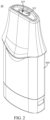
FIG. 2 is a schematic perspective view of an atomizer in the electronic atomizing device shown inFIG. 1 ; -
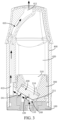
FIG. 3 is a schematic planar sectional view of the atomizer shown inFIG. 2 ; -
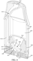
FIG. 4 is a schematic perspective sectional view of the atomizer shown inFIG. 2 ; -
FIG. 5 is a schematic view ofFIG. 4 from another perspective; -
FIG. 6 is a schematic partial perspective exploded sectional view of the atomizer shown inFIG. 2 ; -
FIG. 7 is a schematic longitudinal planar section view ofFIG. 6 in an assembled state; and -
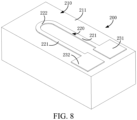
FIG. 8 is a schematic perspective view of an atomizing core in the atomizer shown inFIG. 2 . - To facilitate understanding of this application, the following describes this application more comprehensively with reference to related accompanying drawings.
- A preferred implementation of this application is provided in the accompanying drawings. However, this application may be implemented in many different forms, and is not limited to the implementations described in this specification. On the contrary, the implementations are provided to make understanding of the disclosed content of this application more comprehensive.
- It should be noted that, when an element is referred to as "being fixed to" another element, the element may be directly on the another element, or an intermediate element may be present. When an element is considered to be "connected to" another element, the element may be directly connected to the another element, or an intervening element may be present. The terms "inner", "outer", "left", "right", and similar expressions used in this specification are only for purposes of illustration but not indicate a unique implementation.
- Referring to
FIG. 1 ,FIG. 2 , andFIG. 3 , an electronic atomizingdevice 10 provided in an embodiment of this application includes anatomizer 20 and a power supply 30. Theatomizer 20 may form a detachable connection relationship with the power supply 30. The power supply 30 supplies power to theatomizer 20. Theatomizer 20 converts electrical energy into thermal energy, and an atomizing medium is atomized under the effect of thermal energy into aerosol that can be inhaled by a user. The atomizing medium may be an aerosol-generating substrate such as an oil liquid. Theatomizer 20 includes abase assembly 100, an atomizingcore 200, atop cover assembly 300, and ahousing 400. Both thetop cover assembly 300 and the atomizingcore 200 are disposed in thehousing 400, and at least a part of thebase assembly 100 is accommodated in thehousing 400. Aliquid storage cavity 420 is formed between thetop cover assembly 300 and thehousing 400, and theliquid storage cavity 420 is configured to store a liquid atomizing medium. Aliquid discharge channel 310 is provided on thetop cover assembly 300, and theliquid discharge channel 310 is communication with theliquid storage cavity 420. The atomizingcore 200 is disposed on thetop cover assembly 300, and the atomizing medium in theliquid storage cavity 420 flows into the atomizingcore 200 through theliquid discharge channel 310, so that the atomizingcore 200 atomizes the atomizing medium to form the aerosol. - In some embodiments, an
air inlet channel 110 is provided on thebase assembly 100. When the user inhales, external gas first enters the inside of theatomizer 20 through theair inlet channel 110. Theair inlet channel 110 may be a linear channel, for example, the central axis of theair inlet channel 110 and the central axis of theatomizer 20 are parallel to or coincide with each other. In other words, the central axis of theair inlet channel 110 extends in the vertical direction. Both thetop cover assembly 300 and thehousing 400 are connected to thebase assembly 100. Referring toFIG. 3 ,FIG. 6 , andFIG. 7 , anabutting surface 130 is provided on thebase assembly 100. Both theatomizing core 200 and thetop cover assembly 300 can form an abutting relationship with theabutting surface 130, so that theabutting surface 130 can bear and limit installation of theatomizing core 200 and thetop cover assembly 300, thereby improving installation accuracy and installation efficiency. - In some embodiments, an
inhalation channel 410 is provided on thehousing 400, and the aerosol is finally discharged through theinhalation channel 410 and inhaled by the user. Theinhalation channel 410 includes afirst suction section 411 and asecond suction section 412. Thefirst suction section 411 and thesecond suction section 412 are in communication with each other. Thefirst suction section 411 is connected to the outside. The user may inhale the aerosol at the end of thefirst suction section 411. The central axis of thefirst suction section 411 may be a straight line extending in the vertical direction. For example, the central axis of thefirst suction section 411 may coincide with the central axis of theatomizer 20. The length of thefirst suction section 411 is relatively small, and the length of thesecond suction section 412 is relatively large. In some embodiments, the length of thesecond suction section 412 is greater than three times the length of thefirst suction section 411. The central axis of thesecond suction section 412 is a curve, so that the curved central axis is spaced from the central axis of theatomizer 20. In this embodiment, the curved central axis has a curved portion and a vertical portion that are connected to each other, the vertical portion is parallel to the central axis of theatomizer 20, and the curved portion forms an angle with the central axis of theatomizer 20. - Referring to
FIG. 3 ,FIG. 4 , andFIG. 8 , in some embodiments, theatomizing core 200 includes asubstrate 210, aheating body 220, afirst electrode body 231, and asecond electrode body 232. Thesubstrate 210 may be made of a porous ceramic material, so that thesubstrate 210 has a large quantity of micropores to form a specific porosity. By means of capillary action of the micropores, thesubstrate 210 can absorb the atomizing medium that flows from theliquid storage cavity 420 into theliquid discharge channel 310. Therefore, thesubstrate 210 can transfer and buffer the atomizing medium. Anatomizing cavity 240 is formed between thesubstrate 210 and thebase assembly 100. Thesubstrate 210 has anatomizing surface 211, and theatomizing surface 211 defines a part of a boundary of theatomizing cavity 240 and is configured to atomize the atomizing medium. Thesecond suction section 412 of theinhalation channel 410 is in direct communication with theatomizing cavity 240, and theair inlet channel 110 is also in communication with theatomizing cavity 240. When the user inhales, the external gas enters theatomizing cavity 240 through theair inlet channel 110. The external gas carries the aerosol in theatomizing cavity 240 and successively passes through thesecond suction section 412 and thefirst suction section 411 to be inhaled by the user. Apparently, the external gas successively passes through theair inlet channel 110, theatomizing cavity 240, thesecond suction section 412, and thefirst suction section 411 to enter the oral cavity of the user. The dashed arrow inFIG. 3 represents a flow path of the gas during inhalation. Theheating body 220, thefirst electrode body 231, and thesecond electrode body 232 are all disposed on theatomizing surface 211. For example, the three may be directly attached to theatomizing surface 211, or a groove is provided on theatomizing surface 211, and theheating body 220, thefirst electrode body 231, and thesecond electrode body 232 are at least partially accommodated in the groove. - The
heating body 220 may be made of metal or an alloy material, and both thefirst electrode body 231 and thesecond electrode body 232 may be made of metal or an alloy material. The resistivity of theheating body 220 may be greater than the resistivity of thefirst electrode body 231 and thesecond electrode body 232. Theheating body 220, thefirst electrode body 231, and thesecond electrode body 232 are electrically connected to each other to form a series circuit. Heat generated by theheating body 220 in a unit time is far greater than heat generated by thefirst electrode body 231 and thesecond electrode body 232 in a unit time. Heat generated by thefirst electrode body 231 and thesecond electrode body 232 is extremely small and may be ignored. Theheating body 220 includes acurved section 222 and astraight section 221. There is onecurved section 222. Thecurved section 222 may be semi-circular arc-shaped. The number ofstraight sections 221 is two. The twostraight sections 221 are spaced apart from each other and arranged in parallel, and ends of the twostraight sections 221 are aligned with each other. Thecurved section 222 is connected to ends of the twostraight sections 221 at the same time, so that theentire heating body 220 is substantially U-shaped. Thefirst electrode body 231 and thesecond electrode body 232 are respectively connected to the other ends of the twostraight sections 221. Certainly, thefirst electrode body 231 and thesecond electrode body 232 are respectively electrically connected to a positive electrode and a negative electrode of the power supply 30, so that the power supply 30 supplies power to theheating body 220 through thefirst electrode body 231 and thesecond electrode body 232. When theheating body 220 generates heat, the atomizing medium soaked in theheating body 220 and the atomizing medium on theatomizing surface 211 absorb the heat for atomizing to form the aerosol, and the aerosol is first discharged into theatomizing cavity 240. - Referring to
FIG. 3 ,FIG. 4 , andFIG. 5 , theatomizing cavity 240 has anoutlet 241 for gas to flow out of theatomizing cavity 240, and theoutlet 241 is disposed close to thesecond suction section 412. Apparently, the gas flowing out of theoutlet 241 will directly enter thesecond suction section 412. Along the direction in which the central axis of theatomizer 20 extends, theoutlet 241 is closer to thefirst suction section 411 than theair inlet channel 110. Generally speaking, theoutlet 241 is located obliquely above theair inlet channel 110. When the user inhales at the end of thefirst suction section 411, the flowing direction of the gas flowing into theatomizing cavity 240 from theair inlet channel 110 forms an acute angle A with the flowing direction of the gas in theatomizing cavity 240. For example, the angle formed between the tangent of theair inlet channel 110 at the connection point in communication with theatomizing cavity 240 and the tangent of theatomizing surface 211 is the acute angle A. That is, the angle formed between the tangent of the inner wall surface of theair inlet channel 110 close to the end of theatomizing cavity 240 and the tangent of theatomizing surface 211 is the acute angle A. In other words, theair inlet channel 110 has an end opening on thebase assembly 100 that directly communicates with theatomizing cavity 240, and the normal direction of the end opening forms the acute angle A with the tangent of theatomizing surface 211. Specifically, theatomizing surface 211 is a plane and forms an acute angle B with the central axis of theatomizer 20, and the acute angle B and the acute angle A may be equal. In other words, taking the horizontal plane perpendicular to the central axis of theatomizer 20 as a reference plane, theatomizing surface 211 is inclined relative to the reference plane, that is, theatomizing surface 211 is an inclined plane. Therefore, with the guidance of theatomizing surface 211, the direction of the gas flowing into theatomizing cavity 240 from theair inlet channel 110 may form the acute angle A with the flowing direction of the gas in theatomizing cavity 240. The acute angle B formed between the atomizingsurface 211 and the central axis of theatomizer 20 ranges from 30° to 60°, and a specific value of the acute angle B may be 30°, 45°, 50°, 60°, or the like. - It should be understood that, in this embodiment, the
air inlet channel 110 is of a linear structure, and the tangent at the connection point between theair inlet channel 110 and theatomizing cavity 240 is actually parallel to the extension direction of theair inlet channel 110. In other embodiments, theair inlet channel 110 may alternatively be configured with another structure, for example, an elbow structure. The airflow enters the atomizing cavity in the tangential direction at the connection point between theair inlet channel 110 and theatomizing cavity 240, and the tangential direction is actually the direction of the airflow flowing into theatomizing cavity 240. Further, in this embodiment, theatomizing surface 211 is of a planar structure, and the angle is formed between the tangent of theair inlet channel 110 at the connection point with theatomizing cavity 240 and the tangent of theatomizing surface 211, that is, the angle is formed between the tangent and a tangent plane of theatomizing surface 211 at the connection point. It should be understood that theatomizing surface 211 is of a planar structure, and the tangent plane of theatomizing surface 211 is actually the atomizing surface. In other embodiments, theatomizing surface 211 may further be configured with another structure, for example, an arc cylinder surface or a sphere surface. After being in contact with an acute angle of theatomizing surface 211, the airflow flows to theoutlet 241 along theatomizing surface 211. - If the
atomizing surface 211 is disposed perpendicular to the central axis of theatomizer 20, theatomizing surface 211 will be parallel to the foregoing reference plane, that is, theatomizing surface 211 is a horizontal plane that is not disposed obliquely. In this case, the gas that flows into theatomizing cavity 240 vertically upward from theair inlet channel 110 collides with theatomizing surface 211 to form a "frontal collision", and with guidance of theatomizing surface 211, the gas after the collision changes the flowing direction, so that the air flowing direction is deflected from the vertical direction by 90° and converted into the horizontal direction, that is, the direction of the gas flowing into theatomizing cavity 240 from theair inlet channel 110 is perpendicular to the flowing direction of the gas in theatomizing cavity 240. In this way, the following adverse effects are caused: (1) the gas entering theatomizing cavity 240 "frontally collides" with theatomizing surface 211. The deflection direction of the gas flow is relatively large (that is, deflection by 90°), so that kinetic energy loss of the gas flow is relatively large. On the one hand, the speed of the gas flow is reduced, and on the other hand, the gas flow forms a relatively large turbulence in theatomizing cavity 240, and a strong vortex is generated. In view of the reduced speed of the air flow and the formation of vortex, it is difficult for the gas to carry the aerosol to quickly exit theatomizing cavity 240 and enter theinhalation channel 410 to be absorbed by the user, so that a large amount of aerosol remains in theatomizing cavity 240 for a long time. Therefore, the concentration of the aerosol is reduced, thereby reducing an amount of aerosol actually inhaled by the user in a unit time. In addition, the aerosol remaining in theatomizing cavity 240 cools to form condensate, and the condensate further leaks out of theatomizer 20 through theair inlet channel 110 to form leakage liquid. The leakage liquid may cause erosion to the power supply 30, thereby reducing the service life of the power supply 30, and even causing a risk of assurance of the power supply 30. (2) Because the speed of the air flow is reduced and the vortex is formed, it is difficult for the gas to take away the heat generated by theheating body 220, and as a result, the temperature of theheating body 220 is excessively high, which affects the service life thereof. - However, for the
atomizer 20 in the foregoing embodiment, because theatomizing surface 211 is obliquely disposed, theatomizing surface 211 is an oblique plane, which can effectively prevent the gas flowing into theatomizing cavity 240 vertically upward from theair inlet channel 110 from colliding with theatomizing surface 211 to form a "frontal collision", and ensure that the gas and theatomizing surface 211 form an "oblique collision". In addition, with guidance of theatomizing surface 211, the direction of the gas flowing into theatomizing cavity 240 from theair inlet channel 110 and the flowing direction of the gas in theatomizing cavity 240 form an acute angle. Therefore, after the "oblique collision," the air flowing direction is deflected from the vertical direction by less than 90° and converted into an oblique upward direction, thereby producing at least the following beneficial effects: (1) the kinetic energy loss of the air flow after the "oblique collision" is greatly reduced relative to that of the "frontal collision", so as to ensure that the airflow still maintains a relatively large flow rate. In addition, a turbulence of the airflow in theatomizing cavity 240 is reduced, and generation of the vortex is further reduced. It is ensured that the airflow with the relatively large flow rate quickly leaves theatomizing cavity 240 and enters theinhalation channel 410 to be inhaled by the user, and the stagnation amount and the stagnation time of the aerosol in theatomizing cavity 240 are greatly reduced, so as to reduce formation of the condensate and the leakage liquid, prevent erosion of the leakage liquid to the power supply 30, and improve service life and safety of the power supply 30. (2) Because the gas in theatomizing cavity 240 maintains a relatively large flow rate, the gas can quickly take away the heat generated by theheating body 220, so as to prevent theheating body 220 from being damaged due to an excessively high temperature, and improve the service life of theheating body 220. (3) Because theatomizing surface 211 is obliquely disposed, theentire atomizing core 200 may be obliquely disposed, so as to reduce the total volume of theatomizing cavity 240. Therefore, the total amount of retained aerosol accommodated in theatomizing cavity 240 can be reduced, and formation of condensate and leakage liquid can also be reduced. (4) The aerosol remaining in theatomizing cavity 240 is reduced, and the concentration and the effective absorption amount of the aerosol can be increased, that is, the acquisition amount of the aerosol by the user in a unit time can be increased. - Referring to
FIG. 5 ,FIG. 6 , andFIG. 8 , in some embodiments, thecurved section 222 is connected to the end of thestraight section 221 close to theoutlet 241, and thefirst electrode body 231 and thesecond electrode body 232 are respectively connected to the ends of the twostraight sections 221 away from theoutlet 241, that is, thefirst electrode body 231 and thesecond electrode body 232 are disposed close to theair inlet channel 110. Apparently, thefirst electrode body 231 and thesecond electrode body 232 are also disposed close to the end of theatomizing surface 211 away from theoutlet 241, that is, thefirst electrode body 231 and thesecond electrode body 232 are disposed close to the lower end of theatomizing surface 211. The orthographic projection of theair inlet channel 110 on theatomizing surface 211 is located between thecurved section 222, thefirst electrode body 231, and thesecond electrode body 232. Therefore, gas that flows vertically upward from theair inlet channel 110 into theatomizing cavity 240 is difficult to contact thefirst electrode body 231 and thesecond electrode body 232, so as to avoid turbulence caused by a collision between the airflow and thefirst electrode body 231 and thesecond electrode body 232 and generating a vortex, prevent the speed of the airflow from decreasing, and ensure that gas with a relatively large flow rate carries the aerosol and quickly leaves theatomizing cavity 240, which can also reduce formation of condensate and leakage liquid. - Referring to
FIG. 3 , in some embodiments, the base has aflow guide surface 120, which defines a part of the boundary of theatomizing cavity 240 and is located below theatomizing surface 211, and theflow guide surface 120 is disposed parallel to theatomizing surface 211. By disposing theflow guide surface 120, the space of theatomizing cavity 240 may be further compressed. For example, the volume of theatomizing cavity 240 may be compressed to less than 45 mm3, so as to reduce the total amount of retained aerosol accommodated in theatomizing cavity 240, and further reduce formation of condensate and leakage liquid. In addition, due to the guiding function of theflow guide surface 120, a relatively large deflection and a vortex are prevented from being generated in the direction of the airflow that enters theatomizing cavity 240 from theair inlet channel 110, so as to avoid a kinetic energy loss caused by the deflection, further ensure that the air flow in theatomizing cavity 240 has a relatively large flow rate, and also reduce formation of condensate and leakage liquid. - Referring to
FIG. 3 , in some embodiments, the flowing direction of the gas in theinhalation channel 410 forms an acute angle with the flowing direction of the gas in theatomizing cavity 240. In this way, the airflow flowing out of theatomizing cavity 240 is prevented from being deflected by a direction greater than or equal to 90° in the process of flowing into theinhalation channel 410, thereby reducing the energy loss caused by a collision between the airflow and thehousing 400, so that the airflow also maintains a relatively large flow rate in theinhalation channel 410. In this way, formation of condensate and leakage liquid can also be reduced. - The technical features in the foregoing embodiments may be randomly combined. For concise description, not all possible combinations of the technical features in the embodiments are described. However, provided that combinations of the technical features do not conflict with each other, the combinations of the technical features are considered as falling within the scope described in this specification.
- The foregoing embodiments merely express several implementations of this application. The descriptions thereof are relatively specific and detailed, but should not be understood as limitations to the scope of this application. It should be noted that for a person of ordinary skill in the art, several transformations and improvements can be made without departing from the idea of this application. These transformations and improvements belong to the protection scope of this application. Therefore, the protection scope of the patent of this application shall be subject to the appended claims.
Claims (12)
- An atomizer, comprising:a base assembly provided with an air inlet channel in communication with outside; andan atomizing core, and an atomizing cavity in communication with the air inlet channel and formed between the atomizing core and the base assembly, wherein the atomizing core has an atomizing surface configured to atomize an atomizing medium and define a part of the boundary of the atomizing cavity, and the angle formed between the tangent of the air inlet channel at the connection point in communication with the atomizing cavity and the tangent of the atomizing surface is acute.
- The atomizer of claim 1, wherein the central axis of the air inlet channel is parallel or coincident with the central axis of the atomizer, and the atomizing surface is planar and forms an acute angle with the central axis of the atomizer.
- The atomizer of claim 2, wherein the acute angle between the atomizing surface and the central axis of the atomizer ranges from 30° to 60°.
- The atomizer of claim 2, wherein the base assembly has a flow guide surface spaced apart from the atomizing surface and defining a part of the boundary of the atomizing cavity, and the flow guide surface is parallel to the atomizing surface.
- The atomizer of claim 1, wherein the tangent of the air inlet channel at the connection point in communication with the atomizing cavity is parallel to the extension direction of the air inlet channel.
- The atomizer of claim 2, wherein the atomizing core comprises a substrate, a heating body, a first electrode body, and a second electrode body, the atomizing surface is located on the substrate, wherein the heating body, the first electrode body, and the second electrode body are all disposed on the atomizing surface, the atomizing cavity has an outlet for gas to flow out, and both the first electrode body and the second electrode body are electrically connected to the heating body and disposed close to the end of the atomizing surface away from the outlet.
- The atomizer of claim 6, wherein the heating body comprises a curved section and two straight sections disposed in parallel, the curved section is connected to the end of the straight section close to the outlet, the first electrode body and the second electrode body are respectively connected to ends of the two straight sections away from the outlet, and the orthographic projection of the air inlet channel on the atomizing surface is located between the curved section and the first and second electrode bodies.
- The atomizer of claim 2, wherein the base assembly has an abutting surface, and the edge of the atomizing surface abuts against the abutting surface.
- The atomizer of claim 1, further comprising a housing, wherein both the atomizing core and the base assembly are connected to the housing, the housing is provided with an inhalation channel for outputting aerosol and communicating with the atomizing cavity, and the flowing direction of gas in the inhalation channel forms an acute angle with the flowing direction of the gas in the atomizing cavity.
- The atomizer of claim 9, wherein the inhalation channel comprises a first suction section and a second suction section that are in communication with each other, the length of the second suction section is greater than three times the length of the first suction section, the first suction section is in communication with the outside, and the central axis of the first suction section coincides with the central axis of the atomizer, the second suction section is in communication with the atomizing cavity, and the central axis of the second suction section is spaced apart from the central axis of the atomizer.
- The atomizer of claim 10, wherein the central axis of the second suction section has a curved portion and a vertical portion that are connected to each other, the vertical portion is parallel to the central axis of the atomizer, and the curved portion forms an angle with the central axis of the atomizer.
- An electronic atomizing device, comprising a power supply and the atomizer of any one of claims 1 to 11 connected to the power supply.
Applications Claiming Priority (2)
| Application Number | Priority Date | Filing Date | Title |
|---|---|---|---|
| CN202120219542.3U CN215075497U (en) | 2021-01-26 | 2021-01-26 | Atomizer and electronic atomization device |
| PCT/CN2022/070412 WO2022161129A1 (en) | 2021-01-26 | 2022-01-06 | Atomizer and electronic atomization device |
Publications (2)
| Publication Number | Publication Date |
|---|---|
| EP4275523A1 true EP4275523A1 (en) | 2023-11-15 |
| EP4275523A4 EP4275523A4 (en) | 2024-12-18 |
Family
ID=79325498
Family Applications (1)
| Application Number | Title | Priority Date | Filing Date |
|---|---|---|---|
| EP22745007.9A Pending EP4275523A4 (en) | 2021-01-26 | 2022-01-06 | ATOMIZER AND ELECTRONIC ATOMIZATION DEVICE |
Country Status (4)
| Country | Link |
|---|---|
| US (1) | US20230346035A1 (en) |
| EP (1) | EP4275523A4 (en) |
| CN (1) | CN215075497U (en) |
| WO (1) | WO2022161129A1 (en) |
Families Citing this family (24)
| Publication number | Priority date | Publication date | Assignee | Title |
|---|---|---|---|---|
| CN215075497U (en) * | 2021-01-26 | 2021-12-10 | 深圳麦克韦尔科技有限公司 | Atomizer and electronic atomization device |
| CN113892696A (en) * | 2021-09-14 | 2022-01-07 | 深圳麦克韦尔科技有限公司 | Atomizer and electronic atomization device |
| CN216568378U (en) * | 2021-10-29 | 2022-05-24 | 深圳市卓力能技术有限公司 | Atomizer |
| CN116264913A (en) * | 2021-12-16 | 2023-06-20 | 深圳市卓力能技术有限公司 | An atomizer and electronic atomization equipment |
| CN216875045U (en) * | 2021-12-18 | 2022-07-05 | 深圳麦克韦尔科技有限公司 | Atomization assembly and electronic atomizer |
| AU2022421006A1 (en) * | 2021-12-22 | 2024-05-30 | Nicoventures Trading Limited | Aerosol delivery system |
| CN116406838A (en) * | 2021-12-30 | 2023-07-11 | 深圳麦克韦尔科技有限公司 | Electronic atomization device and its atomizer |
| CN116406837A (en) * | 2021-12-30 | 2023-07-11 | 深圳麦克韦尔科技有限公司 | An electronic atomization device and atomizer thereof |
| WO2023123248A1 (en) * | 2021-12-30 | 2023-07-06 | 深圳麦克韦尔科技有限公司 | Electronic atomization device and atomizer therefor |
| WO2023123165A1 (en) * | 2021-12-30 | 2023-07-06 | 深圳麦克韦尔科技有限公司 | Electronic vaporization apparatus and vaporizer thereof |
| WO2023123243A1 (en) * | 2021-12-30 | 2023-07-06 | 深圳麦克韦尔科技有限公司 | Electronic atomisation device, atomiser, and assembly method for atomiser |
| CN217986687U (en) * | 2022-03-29 | 2022-12-09 | 比亚迪精密制造有限公司 | Electronic cigarette atomization assembly and electronic cigarette |
| CA3247994A1 (en) * | 2022-04-25 | 2025-07-09 | Ald Group Limited | Atomizer |
| WO2024032420A1 (en) * | 2022-08-12 | 2024-02-15 | 常州市派腾电子技术服务有限公司 | Atomization assembly, atomization device, and aerosol generation device |
| CN115349678A (en) * | 2022-08-12 | 2022-11-18 | 深圳市卓尔悦电子科技有限公司 | Atomization device and aerosol generation device |
| WO2024032475A1 (en) * | 2022-08-12 | 2024-02-15 | 常州市派腾电子技术服务有限公司 | Atomization assembly, atomization device, and aerosol generation device |
| WO2024032412A1 (en) * | 2022-08-12 | 2024-02-15 | 常州市派腾电子技术服务有限公司 | Atomization device and aerosol generating device |
| CN115517406A (en) * | 2022-09-02 | 2022-12-27 | 深圳雪雾科技有限公司 | An atomization component and an electronic atomization device |
| CN117814533A (en) * | 2022-09-29 | 2024-04-05 | 深圳麦克韦尔科技有限公司 | Atomizer and electronic atomization device |
| CN115606868A (en) * | 2022-10-09 | 2023-01-17 | 海南摩尔兄弟科技有限公司 | Atomizing core and aerosol generating device |
| CN116326833A (en) * | 2022-12-05 | 2023-06-27 | 深圳雪雾科技有限公司 | An electronic atomization device |
| CN118141161A (en) * | 2022-12-05 | 2024-06-07 | 思摩尔国际控股有限公司 | Electronic atomization device and atomizer thereof |
| CN119423375A (en) * | 2023-07-28 | 2025-02-14 | 深圳市琨坦盛达科技有限公司 | Atomization device and atomization equipment |
| CN120154146A (en) * | 2023-12-16 | 2025-06-17 | 尼科创业贸易有限公司 | Atomizer, cigarette cartridge and aerosol supply system for aerosol supply system |
Family Cites Families (15)
| Publication number | Priority date | Publication date | Assignee | Title |
|---|---|---|---|---|
| US9723876B2 (en) * | 2013-03-15 | 2017-08-08 | Altria Client Services Llc | Electronic smoking article |
| CN206119183U (en) * | 2016-10-20 | 2017-04-26 | 湖南中烟工业有限责任公司 | Atomizer and electron cigarette thereof |
| CN108078009B (en) * | 2016-11-22 | 2024-02-27 | 湖南中烟工业有限责任公司 | Oblique ultrasonic atomizing piece structure and atomizer, electronic cigarette |
| CN206443207U (en) * | 2016-12-30 | 2017-08-29 | 湖南中烟工业有限责任公司 | A kind of spray chamber and ultrasonic electronic cigarette |
| KR102406337B1 (en) * | 2017-04-13 | 2022-06-07 | 차이나 토바코 후난 인더스트리얼 코포레이션 리미티드 | Ultrasonic Atomized Electronic Cigarette |
| CN206949535U (en) * | 2017-05-16 | 2018-02-02 | 湖南中烟工业有限责任公司 | A kind of ultrasonic electronic tobacco atomizer and the electronic cigarette |
| CN207444273U (en) * | 2017-06-30 | 2018-06-05 | 珠海优德科技有限公司 | A kind of electronic smoke atomizer of single-shot side air inlet oil dripping |
| CN208446610U (en) * | 2018-05-24 | 2019-02-01 | 常州市派腾电子技术服务有限公司 | Atomizers and Electronic Cigarettes |
| CN210538906U (en) * | 2019-05-14 | 2020-05-19 | 深圳麦克韦尔科技有限公司 | Electronic atomization device |
| EP3984389A4 (en) * | 2019-06-14 | 2022-07-20 | Shenzhen Smoore Technology Limited | ELECTRONIC ATOMIZER DEVICE, AND ASSOCIATED ATOMIZER AND HEATER ASSEMBLY |
| CN211211432U (en) * | 2019-10-30 | 2020-08-11 | 深圳市合元科技有限公司 | Atomization component and electronic cigarette |
| CN210611013U (en) * | 2019-06-28 | 2020-05-26 | 深圳市合元科技有限公司 | Electronic cigarette atomizer and electronic cigarette |
| CN211910515U (en) * | 2019-12-17 | 2020-11-13 | 深圳市合元科技有限公司 | Atomizers and Electronic Cigarettes |
| CN111920104A (en) * | 2020-07-28 | 2020-11-13 | 深圳麦克韦尔科技有限公司 | Atomizing core, atomizer and electronic atomization device |
| CN215075497U (en) * | 2021-01-26 | 2021-12-10 | 深圳麦克韦尔科技有限公司 | Atomizer and electronic atomization device |
-
2021
- 2021-01-26 CN CN202120219542.3U patent/CN215075497U/en active Active
-
2022
- 2022-01-06 WO PCT/CN2022/070412 patent/WO2022161129A1/en not_active Ceased
- 2022-01-06 EP EP22745007.9A patent/EP4275523A4/en active Pending
-
2023
- 2023-07-11 US US18/350,689 patent/US20230346035A1/en active Pending
Also Published As
| Publication number | Publication date |
|---|---|
| WO2022161129A1 (en) | 2022-08-04 |
| US20230346035A1 (en) | 2023-11-02 |
| CN215075497U (en) | 2021-12-10 |
| EP4275523A4 (en) | 2024-12-18 |
Similar Documents
| Publication | Publication Date | Title |
|---|---|---|
| US20230346035A1 (en) | Vaporizer and electronic vaporization apparatus | |
| CN113892696A (en) | Atomizer and electronic atomization device | |
| US20250288012A1 (en) | Atomizer and electronic atomizing device having the same | |
| CN216493517U (en) | Electronic cigarette components and electronic cigarettes | |
| CN219069464U (en) | Nebulizers and aerosol generating devices | |
| CN220000756U (en) | Suction nozzle assembly and electronic cigarette | |
| CN218737265U (en) | Electronic atomization device and atomizer thereof | |
| CN219047365U (en) | Atomizing device | |
| CN116491704A (en) | Nebulizers and Vaping Devices | |
| EP4166015B1 (en) | Electronic atomizing device and atomizer thereof | |
| CN216088897U (en) | Electronic atomization device and atomizer thereof | |
| CN216293055U (en) | Electronic cigarette atomization assembly and electronic cigarette | |
| CN115944116A (en) | Nebulizers and aerosol generating devices | |
| CN224022898U (en) | Atomizer and aerosol generating device | |
| CN218889284U (en) | Atomizer and electronic atomization device | |
| CN224069725U (en) | Atomizing device | |
| CN224022902U (en) | Atomizer and aerosol generating device | |
| CN117256949A (en) | Electronic atomizing device | |
| CN222031473U (en) | Nozzle and atomizer | |
| CN221355782U (en) | Atomization components and atomization devices | |
| CN219373810U (en) | Atomizing assembly and electromagnetic atomizer | |
| CN222264401U (en) | Nebulizers and nebulizing devices | |
| CN220192214U (en) | Atomization components and aerosol forming devices | |
| CN218571389U (en) | Atomization devices and atomization equipment | |
| CN217284802U (en) | Electronic atomization device and atomizer thereof |
Legal Events
| Date | Code | Title | Description |
|---|---|---|---|
| STAA | Information on the status of an ep patent application or granted ep patent |
Free format text: STATUS: THE INTERNATIONAL PUBLICATION HAS BEEN MADE |
|
| PUAI | Public reference made under article 153(3) epc to a published international application that has entered the european phase |
Free format text: ORIGINAL CODE: 0009012 |
|
| STAA | Information on the status of an ep patent application or granted ep patent |
Free format text: STATUS: REQUEST FOR EXAMINATION WAS MADE |
|
| 17P | Request for examination filed |
Effective date: 20230809 |
|
| AK | Designated contracting states |
Kind code of ref document: A1 Designated state(s): AL AT BE BG CH CY CZ DE DK EE ES FI FR GB GR HR HU IE IS IT LI LT LU LV MC MK MT NL NO PL PT RO RS SE SI SK SM TR |
|
| DAV | Request for validation of the european patent (deleted) | ||
| DAX | Request for extension of the european patent (deleted) | ||
| RAP3 | Party data changed (applicant data changed or rights of an application transferred) |
Owner name: SHENZHEN SMOORE TECHNOLOGY LIMITED |
|
| REG | Reference to a national code |
Ref country code: DE Ref legal event code: R079 Free format text: PREVIOUS MAIN CLASS: A24F0040400000 Ipc: A24F0040485000 |
|
| A4 | Supplementary search report drawn up and despatched |
Effective date: 20241119 |
|
| RIC1 | Information provided on ipc code assigned before grant |
Ipc: A24F 40/10 20200101ALN20241113BHEP Ipc: H05B 3/42 20060101ALI20241113BHEP Ipc: A24F 40/485 20200101AFI20241113BHEP |
|
| RAP3 | Party data changed (applicant data changed or rights of an application transferred) |
Owner name: SHENZHEN SMOORE TECHNOLOGY LIMITED |