EP4274533B1 - Medical device support system including rotational control mechanism - Google Patents
Medical device support system including rotational control mechanism Download PDFInfo
- Publication number
- EP4274533B1 EP4274533B1 EP21844492.5A EP21844492A EP4274533B1 EP 4274533 B1 EP4274533 B1 EP 4274533B1 EP 21844492 A EP21844492 A EP 21844492A EP 4274533 B1 EP4274533 B1 EP 4274533B1
- Authority
- EP
- European Patent Office
- Prior art keywords
- stop
- rotation
- hub
- medical device
- shaft
- Prior art date
- Legal status (The legal status is an assumption and is not a legal conclusion. Google has not performed a legal analysis and makes no representation as to the accuracy of the status listed.)
- Active
Links
Images




Classifications
-
- A—HUMAN NECESSITIES
- A61—MEDICAL OR VETERINARY SCIENCE; HYGIENE
- A61B—DIAGNOSIS; SURGERY; IDENTIFICATION
- A61B90/00—Instruments, implements or accessories specially adapted for surgery or diagnosis and not covered by any of the groups A61B1/00 - A61B50/00, e.g. for luxation treatment or for protecting wound edges
- A61B90/03—Automatic limiting or abutting means, e.g. for safety
-
- A—HUMAN NECESSITIES
- A61—MEDICAL OR VETERINARY SCIENCE; HYGIENE
- A61B—DIAGNOSIS; SURGERY; IDENTIFICATION
- A61B90/00—Instruments, implements or accessories specially adapted for surgery or diagnosis and not covered by any of the groups A61B1/00 - A61B50/00, e.g. for luxation treatment or for protecting wound edges
- A61B90/30—Devices for illuminating a surgical field, the devices having an interrelation with other surgical devices or with a surgical procedure
- A61B90/35—Supports therefor
-
- A—HUMAN NECESSITIES
- A61—MEDICAL OR VETERINARY SCIENCE; HYGIENE
- A61B—DIAGNOSIS; SURGERY; IDENTIFICATION
- A61B90/00—Instruments, implements or accessories specially adapted for surgery or diagnosis and not covered by any of the groups A61B1/00 - A61B50/00, e.g. for luxation treatment or for protecting wound edges
- A61B90/50—Supports for surgical instruments, e.g. articulated arms
-
- E—FIXED CONSTRUCTIONS
- E05—LOCKS; KEYS; WINDOW OR DOOR FITTINGS; SAFES
- E05D—HINGES OR SUSPENSION DEVICES FOR DOORS, WINDOWS OR WINGS
- E05D11/00—Additional features or accessories of hinges
- E05D11/06—Devices for limiting the opening movement of hinges
-
- E—FIXED CONSTRUCTIONS
- E05—LOCKS; KEYS; WINDOW OR DOOR FITTINGS; SAFES
- E05F—DEVICES FOR MOVING WINGS INTO OPEN OR CLOSED POSITION; CHECKS FOR WINGS; WING FITTINGS NOT OTHERWISE PROVIDED FOR, CONCERNED WITH THE FUNCTIONING OF THE WING
- E05F3/00—Closers or openers with braking devices, e.g. checks; Construction of pneumatic or liquid braking devices
- E05F3/20—Closers or openers with braking devices, e.g. checks; Construction of pneumatic or liquid braking devices in hinges
-
- F—MECHANICAL ENGINEERING; LIGHTING; HEATING; WEAPONS; BLASTING
- F21—LIGHTING
- F21V—FUNCTIONAL FEATURES OR DETAILS OF LIGHTING DEVICES OR SYSTEMS THEREOF; STRUCTURAL COMBINATIONS OF LIGHTING DEVICES WITH OTHER ARTICLES, NOT OTHERWISE PROVIDED FOR
- F21V21/00—Supporting, suspending, or attaching arrangements for lighting devices; Hand grips
- F21V21/14—Adjustable mountings
- F21V21/26—Pivoted arms
- F21V21/28—Pivoted arms adjustable in more than one plane
-
- A—HUMAN NECESSITIES
- A61—MEDICAL OR VETERINARY SCIENCE; HYGIENE
- A61B—DIAGNOSIS; SURGERY; IDENTIFICATION
- A61B90/00—Instruments, implements or accessories specially adapted for surgery or diagnosis and not covered by any of the groups A61B1/00 - A61B50/00, e.g. for luxation treatment or for protecting wound edges
- A61B90/03—Automatic limiting or abutting means, e.g. for safety
- A61B2090/033—Abutting means, stops, e.g. abutting on tissue or skin
- A61B2090/034—Abutting means, stops, e.g. abutting on tissue or skin abutting on parts of the device itself
- A61B2090/035—Abutting means, stops, e.g. abutting on tissue or skin abutting on parts of the device itself preventing further rotation
-
- A—HUMAN NECESSITIES
- A61—MEDICAL OR VETERINARY SCIENCE; HYGIENE
- A61B—DIAGNOSIS; SURGERY; IDENTIFICATION
- A61B90/00—Instruments, implements or accessories specially adapted for surgery or diagnosis and not covered by any of the groups A61B1/00 - A61B50/00, e.g. for luxation treatment or for protecting wound edges
- A61B90/50—Supports for surgical instruments, e.g. articulated arms
- A61B2090/508—Supports for surgical instruments, e.g. articulated arms with releasable brake mechanisms
-
- A—HUMAN NECESSITIES
- A61—MEDICAL OR VETERINARY SCIENCE; HYGIENE
- A61G—TRANSPORT, PERSONAL CONVEYANCES OR ACCOMMODATION SPECIALLY ADAPTED FOR PATIENTS OR DISABLED PERSONS; OPERATING TABLES OR CHAIRS; CHAIRS FOR DENTISTRY; FUNERAL DEVICES
- A61G12/00—Accommodation for nursing, e.g. in hospitals, not covered by groups A61G1/00 - A61G11/00, e.g. trolleys for transport of medicaments or food; Prescription lists
- A61G12/002—Supply appliances, e.g. columns for gas, fluid, electricity supply
- A61G12/004—Supply appliances, e.g. columns for gas, fluid, electricity supply mounted on the ceiling
-
- E—FIXED CONSTRUCTIONS
- E05—LOCKS; KEYS; WINDOW OR DOOR FITTINGS; SAFES
- E05Y—INDEXING SCHEME ASSOCIATED WITH SUBCLASSES E05D AND E05F, RELATING TO CONSTRUCTION ELEMENTS, ELECTRIC CONTROL, POWER SUPPLY, POWER SIGNAL OR TRANSMISSION, USER INTERFACES, MOUNTING OR COUPLING, DETAILS, ACCESSORIES, AUXILIARY OPERATIONS NOT OTHERWISE PROVIDED FOR, APPLICATION THEREOF
- E05Y2999/00—Subject-matter not otherwise provided for in this subclass
-
- F—MECHANICAL ENGINEERING; LIGHTING; HEATING; WEAPONS; BLASTING
- F16—ENGINEERING ELEMENTS AND UNITS; GENERAL MEASURES FOR PRODUCING AND MAINTAINING EFFECTIVE FUNCTIONING OF MACHINES OR INSTALLATIONS; THERMAL INSULATION IN GENERAL
- F16D—COUPLINGS FOR TRANSMITTING ROTATION; CLUTCHES; BRAKES
- F16D49/00—Brakes with a braking member co-operating with the periphery of a drum, wheel-rim, or the like
- F16D49/08—Brakes with a braking member co-operating with the periphery of a drum, wheel-rim, or the like shaped as an encircling band extending over approximately 360 degrees
Definitions
- This application relates generally to a rotational control mechanism for a medical device suspension system or carry system for use in, for example, a hospital examination room, a clinic, a surgery room or an emergency room, and more particularly to a rotational control mechanism that simplifies rotational control of an extension arm about a shaft of the medical device support system and provides at least 360° (360 degrees) rotation of the extension arm about the shaft.
- Medical device suspension systems or carry systems are used in health treatment settings such as hospital examination rooms, clinics, surgery rooms and emergency rooms. These systems may suspend or support any variety of medical devices or components including surgical lights, supply consoles, patient monitors, camera detector heads, medical instruments, ventilator systems, suction devices, among others.
- the systems typically include a shaft or support spindle that is suspended from the ceiling or mounted to a wall or stand, and one or more generally horizontal extension arms mounted for rotational movement about the shaft.
- Each extension arm typically has a hub at its proximal end mounted to the shaft for pivotable movement about the shaft, and a support at its distal end for supporting a medical device.
- the extension arm can be rotatably adjusted about the shaft to a desired angular position to provide appropriate access to medical devices and components associated with the arm.
- US2020030056 relates to a medical device support system including a central shaft, an extension arm, and a brake assembly.
- the extension arm has a support for a medical device and a hub at its proximal end mounted to the central shaft for pivotable movement about the central shaft.
- the brake assembly is secured in the hub for rotation therewith and includes first and second backing portions and first and second liners supported by the backing portions. At least the first liner is supported by the first backing portion by the first liner being snap-fitted to the first backing portion.
- the brake assembly includes an actuator configured to flex the first and second backing portions to urge the first and second liners toward and away from each other to respectively increase and decrease a frictional braking force to the central shaft.
- extension arm It is desirable to limit the rotation of the extension arm about the shaft for example to prevent collision of medical devices at the distal ends of the arms, or to prevent undue strain on electrical or communication lines passing through the shaft and the extension arm.
- the extension arm is equipped with a fixed feature in the hub that contacts a fixed feature on the shaft that prevents further rotation.
- rotational control mechanisms in some medical device suspension systems or carry systems, there remain various shortcomings, drawbacks, and disadvantages relative to certain applications.
- the rotational control mechanism limits rotation of the extension arm to below 360° (360 degrees), which may limit options for some installations.
- Other rotational control mechanisms require multiple stacked components, which increase the volumetric footprint of the mechanisms and complicates their integration into the hub of the extension arm.
- the application relates to a rotational control mechanism for a medical device support system, in which the rotational control mechanism enables at least 360° (360 degrees) rotation of the extension arm about the shaft, and also embodies fewer components and a smaller volumetric footprint than heretofore attained, thus simplifying and adding efficiency to the factory assembly and field service of the medical device support system.
- a medical device support system includes a shaft, an extension arm, a guide channel member, and a floating stop.
- the extension arm may have a support for a medical device and a hub at its proximal end mounted to the shaft for pivotable movement about a rotation axis of the shaft.
- the guide channel member may be fixed to the shaft.
- the guide channel member may include an elongated cavity that defines first and second contact faces at opposite ends of the cavity.
- the floating stop may be movable within the elongated cavity of the guide channel member and movable relative to the hub.
- the hub may be pivotably mounted for a range of at least 360° (360 degrees) rotation about the rotation axis, wherein the at least 360° (360 degrees) rotation range is based on a compound of a first rotation range and a second rotation range, wherein the first rotation range is defined by a fixed stop of the hub configured to move between first and second contact faces of a radially outer portion of the floating stop, wherein the second rotation range is defined by a radially inner portion of the floating stop configured to move between the first and second contact faces of the elongated cavity of the guide channel member.
- the invention may include one or more of the following additional features separately or in combination.
- the guide channel member may include a rotation boundary member that is fixed to the shaft, the rotation boundary member defining as boundaries the first and second contact faces at opposite ends of the cavity.
- the rotation boundary member may include a ring shape structure and the ring shape structure may be fixed to the shaft.
- the elongated cavity may have an arc shape.
- the guide channel member may include a lower guide wall for axially supporting the floating stop.
- the guide channel member may include an arc shape track and the floating stop may include an arc shape groove, wherein the arc shape groove slidably receives the arc shape track to angularly guide the floating stop within the elongated cavity and about the rotation axis.
- the floating stop may be configured to prevent rotation of the hub about the rotation axis beyond the at least 360° (360 degrees) rotation range.
- the hub may be pivotably mounted for at least 360° (360 degrees) rotation from a first stop to a second stop and vice versa, wherein the first stop limits counterclockwise rotation of the hub about the rotation axis and the second stop limits clockwise rotation of the hub about the rotation axis.
- the first stop may include the fixed stop of the hub in engagement with the first contact face of the radially outer portion of the floating stop, and the radially inner portion of the floating stop in engagement with the first contact face of the elongated cavity of the guide channel member.
- the second stop may include the fixed stop of the hub in engagement with the second contact face of the radially outer portion of the floating stop, and the radially inner portion of the floating stop in engagement with the second contact face of the elongated cavity of the guide channel member.
- the radially outer portion of the floating stop and the radially inner portion of the floating stop may lie in the same plane and the plane may be perpendicular to the rotation axis.
- the fixed stop of the hub and the radially inner portion of the floating stop may lie in the same plane and the plane may be perpendicular to the rotation axis.
- the radially outer portion of the floating stop may include a tab, and the first and second contact faces of the radially outer portion of the floating stop may be on opposite peripheral sides of the tab.
- the radially inner portion of the floating stop may have first and second contact faces on opposite sides thereof, and the second rotation range may be defined by movement of the radially inner portion between a location at which the first contact face of the radially inner portion engages the first contact face of the elongated cavity of the guide channel member and a location at which the second contact face of the radially inner portion engages the second contact face of the elongated cavity of the guide channel member.
- the shaft may have an axial hollow and a radial aperture and the ring shape structure may be fixed to the shaft at a position to allow passage of electrical and communication lines through the axial hollow, through the ring shape structure, through the radial aperture, and into a longitudinally extending cavity in the extension arm.
- the hub of the extension arm may include upper and lower pivot bearings configured to pivotably engage the hub with the shaft, and a radial opening positioned axially between the upper and lower pivot bearings, and the ring shape structure may be positioned to allow passage of the electrical and communication lines between the upper and lower pivot bearings, through the radial opening of the hub, and into the longitudinally extending cavity in the extension arm.
- a medical device support system includes a shaft, an extension arm, a guide channel member, and a floating stop.
- the extension arm may have a support for a medical device and a hub at its proximal end mounted to the shaft for pivotable movement about a rotation axis of the shaft.
- the guide channel member may be fixed to the shaft.
- the guide channel member may include an elongated cavity that defines first and second contact faces at opposite ends of the cavity.
- the floating stop may be movable within the elongated cavity of the guide channel member and movable relative to the hub.
- the hub may be pivotably mounted for a range of at least 360° (360 degrees) rotation about the rotation axis from a first stop to a second stop and vice versa, wherein the first stop limits counterclockwise rotation of the hub about the rotation axis and the second stop limits clockwise rotation of the hub about the rotation axis, wherein the first stop includes a radially inner portion of the floating stop in engagement with the first contact face of the elongated cavity of the guide channel member, and wherein the second stop includes the radially inner portion of the floating stop in engagement with the second contact face of the elongated cavity of the guide channel member.
- the invention may include one or more of the following additional features separately or in combination.
- the first stop may include the fixed stop of the hub in engagement with the first contact face of the radially outer portion of the floating stop
- the second stop may include the fixed stop of the hub in engagement with the second contact face of the radially outer portion of the floating stop.
- a method of rotating an extension arm about a shaft of a medical device support system the extension arm having a support for a medical device and a hub at its proximal end mounted to the shaft for pivotable movement about a rotation axis of the shaft, wherein a guide channel member is fixed to the shaft, wherein the guide channel member includes an elongated cavity that defines first and second contact faces at opposite ends of the cavity, wherein a floating stop is movable within the elongated cavity of the guide channel member and movable relative to the hub, the method including rotating the hub over a range of at least 360° (360 degrees) about the rotation axis, wherein the at least 360° (360 degrees) rotation range is based on a compound of movement over a first rotation range and movement over a second rotation range, wherein movement over the first rotation range includes moving a fixed stop of the hub between first and second contact faces of a radially outer portion of the floating stop, and wherein movement over the second rotation range includes moving
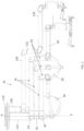
- Figs. 1-8 show a medical device support system 10 that includes a shaft 14, at least one extension arm 16 having a support 20 for a medical device 30 and a hub 34 at its proximal end mounted to the shaft 14 for pivotable movement about a rotation axis A-A of the shaft 14, and a rotational control mechanism 40 integrated into the hub 34 for controlling the amount of rotation of the extension arm 16 about the shaft 14.
- the rotational control mechanism 40 includes a guide channel member 44, a fixed stop 70 connected to a wall of the hub 34, and a floating stop 60 having a radially outer portion 80 and a radially inner portion 90, the radially inner portion 90 being relatively closer to the rotation axis A-A than the radially outer portion 80.
- the guide channel member 44 in the illustrative embodiment includes a rotation boundary member 46 that is fixed to the shaft 14.
- the guide channel member 44 includes an elongated cavity 50 that defines first and second contact faces 52, 54 at opposite ends of the cavity 50.
- the floating stop 60 is movable within the elongated cavity 50 of the guide channel member 44 and movable relative to the hub 34.
- the hub 34 is pivotably mounted for a range of at least 360° (360 degrees) rotation about the rotation axis A-A, wherein the at least 360° (360 degrees) rotation range is based on a compound of a first rotation range and a second rotation range.
- the first rotation range is defined by the fixed stop 70 of the hub 34 configured to move between first and second contact faces 82, 84 of the radially outer portion 80 of the floating stop 60.
- the second rotation range is defined by the radially inner portion 90 of the floating stop 60 configured to move between the first and second contact faces 52, 54 of the elongated cavity 50 of the guide channel member 44.
- the illustrative medical device support system 10 is a suspension type carrying support system for use in a hospital examination room, a clinic, a surgery room, an emergency room, among others.
- the shaft 14 extends along an axis A-A, which also represents the rotation axis A-A of the shaft 14 about which the extension arm 16 pivots.
- the shaft 14 may be fixed to a ceiling support 110 to remain stationary relative to the ceiling.
- the medical device support system 10 may have any suitable suspension or carrying structure and that the shaft 14 may be attached to a ceiling as shown, or to a wall, floor, movable cart, or a combination of the foregoing.
- the shaft 14 of the medical device support system 10 has a cylindrical shape in axial cross section and defines an axial hollow 112 and radial aperture 116 therein, and extends vertically downward from the ceiling support 110.
- a column section 114 surrounds an upper portion of the shaft 14.
- the axial hollow 112 and the column section 114 house upper portions of accessory and service lines such as power cables for surgical lights and other power requirements, control wiring for control electronics, optical fibers for data communication, and/or tubing for irrigation, suction, etc.
- a plurality of extension arms 16, three in the illustrative embodiment, are mounted for rotatable movement to the shaft 14 and extend laterally outward from the shaft 14. In the Fig. 1 embodiment, the extension arms 16 extend horizontally, or perpendicularly, relative to the shaft 14.
- An additional extension arm 130, support arm 132, and medical device 134 may be pivotably mounted to a separate central shaft 136 radially offset from the central shaft 14.
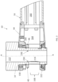
- each extension arm hub 34 may include upper and lower bearing mounts 150, 152, shown in Figs. 2-6 , that house respective upper and lower pivot bearings mounted to the shaft 14. Any suitable pivot bearings may be used to enable the relative rotational movement between the extension arm 16 and the shaft 14, including for example ball bearings, sleeve bearings, bushings, rotary joints and/or swivel joints.
- a brake assembly 160 may be secured in the hub 34 for rotation therewith to selectively increase and decrease a frictional braking force to the shaft 14.
- the brake assembly 160 is positioned below the upper bearing 150 and above the guide channel member 44 or the rotation boundary member 46 of the guide channel member 44.
- Each hub 34 provides a radial opening 164 positioned axially between the upper and lower pivot bearings 150, 152 for routing accessory and service lines from the axial hollow 112 and/or the upper column section 114 through the radial aperture 116 and to a longitudinally extending cavity 166 of the extension arm 16, and/or vice versa.
- Each hub 34 is also provided with an access opening 168 to enable access to the shaft 14, the rotational control mechanism 40, the upper and lower pivot bearings 150, 152, the brake assembly 160, accessory and service lines, and/or other components within the hub 34.
- a suitable brake assembly 160 and access opening 168 for the illustrative embodiment are described in U.S. Patent Application Nos. 16/517,703 ; 16/517,704 ; 16/517,707 ; and 16/517,708 .
- the rotational control mechanism 40 is made up of a combination of components from the hub 34 of the extension arm 16, the guide channel member 44, and the floating stop 60.
- the hub 34 includes the fixed stop 70.
- the floating stop 60 includes the radially outer portion 80 and the radially inner portion 90.
- the guide channel member 44 includes an elongated cavity 50.
- the extension arm 16 and its hub 34 and the fixed stop 70 of the rotational control mechanism 40 are movable relative to the shaft 14.
- the floating stop 60 including its radially outer and inner portions 80, 90 is movable within the elongated cavity 50 of the guide channel mechanism 44 and movable relative to the hub 34 and the fixed stop 70.
- Each of the components of the rotational control mechanism 40 provides contact faces, that is, faces for abutting engagement, to control the amount of rotation of the extension arm 16 about the rotation axis A-A of the shaft 14.
- the fixed stop 70 has first and second contact faces 72, 74 on opposite peripheral ends of the fixed stop 70.
- the radially outer portion 80 has first and second contact faces 82, 84 on opposite peripheral ends of the radially outer portion 80.
- the radially inner portion 90 has first and second contact faces 92, 94 on opposite peripheral ends of the radially inner portion 90.
- the elongated cavity 50 defines first and second contact faces 52, 54 at opposite ends of the cavity 50.
- the floating stop 60 is configured to prevent rotation of the hub 34 about the rotation axis A-A beyond the at least 360° (360 degrees) rotation range.
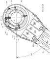
- the hub 34 is pivotably mounted for at least 360° (360 degrees) rotation from a first stop shown in Fig. 8 to a second stop shown in Fig. 10 , and vice versa.
- the first stop limits counterclockwise rotation of the hub 34 about the rotation axis A-A.
- the first stop defines the most counterclockwise rotation the hub 34 and thus the extension arm 16 obtain about the shaft 14.
- the first stop, or most counterclockwise rotation of the extension arm 16 positions the extension arm 16 at 54° (54 degrees) relative to a horizontal line across the page. As shown in Fig.
- the second stop limits clockwise rotation of the hub 34 about the rotation axis A-A.
- the second stop defines the most clockwise rotation the hub 34 and associated extension arm 16 obtain about the shaft 14.
- the second stop, or most clockwise rotation of the extension arm 16 positions the extension arm 16 at 54° (54 degrees) relative to the horizontal line across the page.
- the rotation of the extension arm 16 and its hub 34 about the shaft 14 is 360° (360 degrees), which, going from Fig. 8 to Fig. 10 , is 360° (360 degrees).
- the first stop includes the fixed stop 70 of the hub 34 in engagement with the first contact face 82 of the radially outer portion 80 of the floating stop 60, and the radially inner portion 90 of the floating stop 60 in engagement with the first contact face 52 of the elongated cavity 50 of the guide channel member 44.
- the second stop includes the fixed stop 70 of the hub 34 in engagement with the second contact face 84 of the radially outer portion 80 of the floating stop 60, and the radially inner portion 90 of the floating stop 60 in engagement with the second contact face 54 of the elongated cavity 50 of the guide channel member 44.
- the rotational control mechanism 40 facilitates the at least 360° (360 degrees) rotation range based on a compound of a first rotation range and a second rotation range.
- the first rotation range is defined by the fixed stop 70 of the hub 34 being configured to move between the first and second contact faces 82, 84 of the radially outer portion 80 of the floating stop 60.
- the angular span between the first and second contact faces 72, 74 of the fixed stop 70 is about 20-degrees.
- the radially outer portion 80 of the floating stop 60 has an angular span of about 20-degrees between its first and second contact faces 82, 84.
- the first rotation range is defined by movement of the fixed stop 70 between a location shown in Fig. 8 at which the first contact face 72 of the fixed stop 70 engages the first contact face 82 of the radially outer portion 80 of the floating stop 60 and a location at which the second contact face 74 of the fixed stop 70 engages the second contact face 84 of the radially outer portion 80 of the floating stop 60.
- the first rotation range is defined by the fixed stop 70 moving from the position shown in Fig.
- the first rotation range of the rotational control mechanism 40 is approximately 320° (320 degrees) (360 minus 20 minus 20).
- the second rotation range is defined by the radially inner portion 90 of the floating stop 60 being configured to move between the first and second contact faces 52, 54 of the elongated cavity 50 of the guide channel member 44.
- the angular span between the first and second contact faces 52, 54 of the elongated cavity 50 is about 60-degrees.
- the radially inner portion 90 of the floating stop 60 has an angular span of about 20-degrees between its first and second contact faces 92, 94.
- the second rotation range is defined by movement of the radially inner portion 90 of the floating stop 60 between a location at which the first contact face 92 of the radially inner portion 90 engages the first contact face 52 of the elongated cavity 50 of the guide channel member 44 and a location shown in Fig.
- the second rotation range is defined by the radially inner portion 90 moving from the position shown in Fig. 8 where the first contact face 92 abuttingly engages the first contact face 52, to a position where the second contact face 94 abuttingly engages the second contact face 54; that is, in Fig.
- the radially inner portion 90 moves from the first contact face 52 of the elongated cavity 50 clockwise to the second contact face 54 of the elongated cavity 50.
- the second rotation range of the rotational control mechanism 40 is approximately 40° (40 degrees) (60 minus 20).
- the first and second rotation ranges usually will not be completed in serial fashion but rather at least partially in parallel fashion.
- Fig. 9 for example, where the hub 34, relative to the Fig. 8 position, has been rotated clockwise about the shaft 14 about 180° (180 degrees) to a position at which the fixed stop 70 has reached 180° (180 degrees) from the radially outer portion 80 of the floating stop 60, that is, the middle of the first rotation range, and the radially inner portion 90 has reached the middle of the elongated cavity 50, that is, the middle of the second rotation range.
- the rotational control mechanism 40 can provide a greater than 360° (360 degrees) rotation range by adjusting any of its components, for the example the width (angular span) of any of the elongated cavity 50, the fixed stop 70, the radially outer portion 80 of the floating stop 60, and/or the radially inner portion 90 of the floating stop 60.
- the fixed stop 70 is 1.0° (1.0 degree) smaller in width in Figs. 8-10
- the first stop, or most counterclockwise rotation of the extension arm 16 positions the extension arm 16 at 55° (55 degrees) relative to a horizontal line across the page, and in Fig.
- the second stop, or most clockwise rotation of the extension arm 16 positions the extension arm 16 at 54° (54 degrees) relative to the horizontal line across the page.
- the total rotation of the extension arm 16 and its hub 34 about the shaft 14 is then 361° (361 degrees), where the first rotation range is 321° (321 degrees) (360 minus 19 minus 20) and the second rotation range is 40° (40 degrees) (60 minus 20).
- the angular span between the first and second contact faces 72, 74 may be in a range from about 1-degree to about 60-degrees, even more particularly between 1-degree and 45-degrees, such as about 20-degrees in the illustrated embodiment.
- the radially outer portion 80 of the floating stop 60 may have an angular span in a range from about 1-degree to about 60-degrees, even more particularly between 1-degree and 45-degrees, such as about 20-degrees in the illustrated embodiment.
- the elongated cavity 50 forms an arcuate segment defined by an angular span between the opposite first and second contact faces 52, 54 that may be in a range from about 1-degree to about 180-degrees, and even more particularly from about 10-degrees to about 90-degrees, such as about 60-degrees in the illustrated embodiment.
- the radially inner portion 90 of the floating stop 60 may have an angular span in a range from about 1-degree to about 60-degrees, even more particularly between 1-degree and 45-degrees, such as about 20-degrees in the illustrated embodiment.
- the at least 360-degrees range provided by the rotational control mechanism 40 may be in a range from 360-degrees to less than 720-degrees, more particularly from 360-degrees to 540-degrees, and even more particularly from 360-degrees to 450-degrees, such as about 360-degrees in the illustrated embodiment.
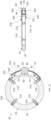
- Figs. 7 and 11-13 show greater detail of the guide channel member 44 and the floating stop 60 of the rotation control mechanism 40.
- the guide channel member 44 includes the rotation boundary member 46, an upper guide member 200, and a lower guide member 202.
- the rotation boundary member 46 includes a ring shape structure wherein the inner diameter of the ring shape structure is slightly greater than the outer diameter of the shaft 14 to enable the rotation boundary member 46 to be slid axially onto the shaft 14 during assembly.
- the central axis of the ring shape structure coincides with the rotation axis A-A.
- the rotation boundary member 46 is fixed to the shaft 14 by four fasteners 210.
- the fasteners 210 are socket set screws.
- the fasteners 210 are threaded into respective threaded openings 220 in the rotation boundary member 46 and into respective blind holes 230 in the shaft 14.
- the centerlines of the fasteners 210, the threaded openings 220, and the blind holes 230 protrude radially from and perpendicular to the rotation axis A-A.
- the guide channel member 44 is fixed to the shaft 14 and, as shown in Fig. 12 , the tops of the fasteners 210 are below the outer radius of the ring shape structure. As such, the tops of the fasteners 210 will not interfere with the fixed stop 70 during rotation of the extension arm 16 about the rotation axis A-A.
- the fasteners 210 and the threaded openings 220 are positioned angularly outside of the arcuate span of the elongated cavity 50, and angularly outside of the upper and lower guide members 200, 202. It will be appreciated that the quantity and location of the fasteners 210 and the threaded openings 220 need not be limited as such, and other embodiments are contemplated. Any number of fasteners 210 may be used so long as the rotation boundary member 46 is securely fastened to the shaft 14.
- three fasteners 210 and three threaded openings 220 may be used, where two are located adjacent to the respective opposite sides of the elongated cavity 50 and angularly outside of the upper and lower guide members 200, 202 and one is located diametrically opposite the angular center of the elongated cavity 50.
- the shaft 14 would have three blind holes 230 to accommodate the corresponding three fasteners 210.
- the fasteners 210, or even a single fastener 210, and a corresponding threaded opening or openings 220 in the rotation boundary member 46 may be located within the arcuate span of the elongated cavity 50, that is, between the opposite first and second contact faces 52, 54 of the elongated cavity 50.
- the threaded openings 220 may be in the arc shape wall of the cavity 50 for example.
- the guide channel member 44 is fixed to the shaft 14 and the tops of the fasteners 210 are below the outer radius of the arc shape wall such that the tops of the fasteners 210 will not interfere with the movement of the floating stop 60 within the elongated cavity 50 during rotation of the extension arm 16 about the rotation axis A-A.
- the rotation boundary member 46 includes a ring shape structure.
- Other shape structures may be suitable and are contemplated.
- the rotation boundary member 46 may instead include an arc shape structure wherein the inner radius of the arc shape structure is slightly greater than the outer radius of the shaft 14 to enable the rotation boundary member 46 to be snugly fitted on the shaft 14 during assembly.
- Such arc shape structure would have an arcuate span sized to provide the elongated cavity 50 and the two fasteners 210 located adjacent to the respective opposite sides of the elongated cavity 50 and angularly outside of the upper and lower guide members 200, 202, in which case the shaft 14 would have two corresponding blind holes 230 to accommodate the two fasteners 210.
- the upper guide member 200 and the lower guide member 202 are mounted to the rotation boundary member 46 by respective upper and lower fasteners 240, 242.
- the fasteners 240, 242 are socket flat head cap screws.
- the upper fasteners 240 are inserted through through hole openings 250 in the upper guide member 200 and threaded into respective threaded openings 260 in the rotation boundary member 46.
- the lower fasteners 242 are inserted through through hole openings 252 in the lower guide member 202 and threaded into respective threaded openings 262 in the rotation boundary member 46.
- the centerlines of the fasteners 240, 242, the through hole openings 250, 252, and the threaded openings 260, 262 extend axially and are parallel to the rotation axis A-A.
- the upper guide member 200 is secured to the rotation boundary member 46 and the tops of the flat heads of the upper fasteners 240 are substantially flush with or slightly below the upper surface of the upper guide member 200.
- the lower guide member 202 is secured to the rotation boundary member 46 and the tops of the flat heads of the lower fasteners 242 are substantially flush with or slightly below the lower surface of the lower guide member 200.
- the upper and lower guide members 200, 202 add relatively little height to the guide channel member 44, thereby contributing to the rotational control mechanism 40 having a relatively smaller volumetric footprint than heretofore attained.
- the fasteners 240, 242, the through hole openings 250, 252, and the threaded openings 260, 262 are positioned angularly outside of the arcuate span of the elongated cavity 50, and angularly inside of the fasteners 210 and threaded openings 220 used for securing the rotation boundary member 46 to the shaft 14.
- the upper and lower guide members 200, 202 have an identical geometry for economy of manufacture. As such, the upper guide member 200 and the upper fasteners 240 are staggered angularly relative to the lower guide member 202 and the lower fasteners 242, in the illustrative embodiment approximately 10° (10 degrees).
- the quantity and location of the fasteners 240, 242, the through hole openings 250, 252 and the threaded openings 260, 262 may be different from that illustrated, and other embodiments are contemplated.
- Any number of fasteners 240, 242 may be used so long as the upper and lower guide members 200, 202 are securely fastened to the rotation boundary member 46.
- a single fastener may be used to secure the upper guide member 200 to the rotation boundary member 46
- a single fastener may be used to secure the lower guide member 202 to the rotation boundary member 46, where the guide members 200, 202 are provided with projections and/or recesses that engage respective recesses and/or projections in the rotation boundary member 46 to prevent movement therebetween.
- the fasteners 240, 242, the through hole openings 250, 252, and the threaded openings 260, 262 may instead be positioned angularly outside of the fasteners 210 and the threaded openings 220 used for securing the rotation boundary member 46 to the shaft 14; in this way, the fasteners 210 and the threaded openings 220, as well as the blind holes 230 in the shaft 14, may be evenly spaced, i.e. equally angularly spaced, about the rotation axis A-A.
- the upper and lower guide members 200, 202 may have different geometries and different corresponding locations for the through hole openings 250, 252 to accommodate the fasteners 240, 242.
- the upper and lower guide members 200, 202 support, retain, and guide the floating stop 60.
- the upper guide member 200 includes an upper arc shape wall 280 and an upper arc shape track 290 projecting downwardly from the upper arc shape wall 280.
- the lower guide member 202 includes a lower arc shape wall 282 and a lower arc shape track 292 projecting upwardly from the lower arc shape wall 282.
- the floating stop 60 has an arc shape and includes upper and lower arc shape grooves 300, 302 in respective upper and lower surfaces of the floating stop 60.
- the floating stop 60 has an inner radius that is a first radial distance from the rotation axis A-A and an outer radius that is a second radial distance from the rotation axis A-A.
- the upper and lower arc shape grooves 300, 302 are located a radial distance from the rotation axis A-A that is greater than the first radial distance and less than the second radial distance. As shown in Figs. 12 and 13 , the upper and lower arc shape grooves 300, 302 are positioned at substantially the same radial distance from the rotation axis A-A as the respective upper and lower arc shape tracks 290, 292.
- the rotation boundary member 46 has an arc shape cut out that forms the elongated cavity 50, the opposite ends of the arc shape cut out providing the boundaries that form the first and second contact faces 52, 54 at opposite ends of the cavity 50.
- the arc shape cut out has an arc shape wall that is located a radial distance from the rotation axis A-A that is slightly less than the first radial distance that the inner radius of the floating stop 60 is located from the rotation axis A-A, this enables the inner radius of the floating stop 60 to slidably and/or freely move relative to the arc shape wall of the arc shape cut out during movement of the floating stop 60 within the elongated cavity 50 formed by the arc shape cut out.
- the upper and lower arc shape walls 280, 282 of the respective upper and lower guide members 200, 202 axially support the floating stop 60.
- the lower arc shape wall 282 axially supports the floating stop 60 to prevent axially downward movement of the floating stop 60 due to for example gravitational forces or incidental downward forces exhibited by the floating stop 60 during movement within the elongated cavity 50.
- the upper arc shape guide wall 280 axially supports the floating stop 60 to prevent axially upward movement of the floating stop 60 due to for example incidental upward forces exhibited by the floating stop 60 during movement within the elongated cavity 50.
- the upper and lower arc shape grooves 300, 302 of the floating stop 60 slidably receive the respective upper and lower arc shape tracks 290, 292 to radially retain the floating stop 60 and to angularly guide the floating stop 60 within the elongated cavity 50 and about the rotation axis A-A.
- the floating stop 60 includes the afore described radially outer portion 80 and radially inner portion 90.
- the radially outer portion 80 is located radially outward from the upper and lower arc shape tracks 290, 292 and the upper and lower arc shape grooves 300, 302.
- the radially inner portion 90 of the floating stop 60 is located radially inward from the upper and lower arc shape tracks 290, 292 and the upper and lower arc shape grooves 300, 302.
- the rotational control mechanism 40 can provide a greater than 360° (360 degrees) rotation range by adjusting the width (angular span) of the radially outer portion 80 of the floating stop 60, and/or the radially inner portion 90 of the floating stop 60.
- the angular span of the radially outer portion 80 of the floating stop 60 i.e. the portion of the floating stop 60 radially outward from the upper and lower arc shape tracks 290, 292 and the upper and lower arc shape grooves 300, 302 may be made relatively smaller than what is shown in the illustrative embodiment.
- the angular span of the radially inner portion 90 of the floating stop 60 i.e. the portion of the floating stop 60 radially inward from the upper and lower arc shape tracks 290, 292 and the upper and lower arc shape grooves 300, 302
- the upper guide member 200 may be omitted, for example where upward forces exhibited by the floating stop 60 during movement within the elongated cavity 50 do not cause the floating stop 60 to shift and/or bind within the elongated cavity 50.
- the amount of radially inward protrusion of the radially inner portion 90 of the floating stop 60 relative to the outer radius of the guide channel member 44, or relative to the upper and lower arc shape tracks 290, 292 is such that the first and second contact faces 92, 94 of the radially inner portion 90 are at the same radial distance from the rotation axis A-A (or on the same circumference) as the first and second contact faces 52, 54 of the elongated cavity 50, and thus in operation abuttingly engage the respective first and second contact faces 52, 54.
- the fixed stop 70 is formed as part of the hub structure of the hub 34 and includes a block 70 with beveled edges forming the respective first and second contact faces 72, 74 on opposite peripheral sides of the block 70.
- the block 70, or fixed stop 70 protrudes axially downward from the hub structure that houses the brake assembly 160, which positions the fixed stop 70 and its first and second contact faces 72, 74 at the same axial location as the radially outer portion 80 of the floating stop 60 and its first and second contact faces 82, 84.
- the fixed stop 70 need not be formed as part of the hub structure of the hub 34 and may instead be a separate block that is attached to the hub structure.
- the amount of radially outward protrusion of the radially outer portion 80 of the floating stop 60 relative to the outer radius of the guide channel member 44, or relative to the upper and lower arc shape tracks 290, 292 is such that the first and second contact faces 82, 84 of the radially outer portion 80 are at the same radial distance from the rotation axis A-A (or on the same circumference) as the first and second contact faces 72, 74 of the fixed stop 70, and thus in operation abuttingly engage the respective first and second contact faces 72, 74.
- the radially outer portion 80 of the floating stop 60 and the radially inner portion 90 of the floating stop 60 lie in the same plane and the plane is perpendicular to the rotation axis A-A.
- the rotational control mechanism 40 embodies fewer components and a smaller volumetric footprint than heretofore attained and simplifies and adds efficiency to the factory assembly and field service of the medical device support system 10.
- the radially outer portion 80 of the floating stop 60 and the elongated cavity 50 of the guide channel member 44 lie in the same plane and the plane is perpendicular to the rotation axis A-A.
- the radially outer portion 80, the radially inner portion 90, and the elongated cavity 50 lie in the same plane perpendicular to the rotation axis A-A.
- the invention need not be limited as such and other embodiments are contemplated.
- the radially outer portion 80 may be located in a plane axially above or axially below the plane in which the radially inner portion 90 and the elongated cavity 50 lies.
- the radially outer portion 80 may be located in a plane axially above or axially below the plane in which the radially inner portion 90 lies, and the elongated cavity 50 may have an axial height such that the radially outer portion 80 and the radially inner portion 90, although themselves in different planes, both lie in the axial height plane of the elongated cavity 50.
- the fixed stop 70 of the hub 34 and the radially inner portion 90 of the floating stop 60 lie in the same plane and the plane is perpendicular to the rotation axis A-A.
- the rotational control mechanism 40 embodies fewer components and a smaller volumetric footprint than heretofore attained and simplifies and adds efficiency to the factory assembly and field service of the medical device support system 10.
- the fixed stop 70 of the hub 34 and the elongated cavity 50 of the guide channel member 44 lie in the same plane and the plane is perpendicular to the rotation axis A-A.
- the fixed stop 70, the radially inner portion 90, and the elongated cavity 50 lie in the same plane perpendicular to the rotation axis A-A.
- the invention need not be limited as such and other embodiments are contemplated.
- the fixed stop 70 may be located in a plane axially above or axially below the plane in which the radially inner portion 90 and the elongated cavity 50 lies.
- the fixed stop 70 may be located in a plane axially above or axially below the plane in which the radially inner portion 90 lies, and the elongated cavity 50 may have an axial height such that the fixed stop 70 and the radially inner portion 90, although themselves in different planes, both lie in the axial height plane of the elongated cavity 50.
- the radially outer portion 80, the radially inner portion 90, the elongated cavity 50, and the fixed stop 70 all lie in the same plane perpendicular to the rotation axis A-A.
- the rotational control mechanism 40 embodies fewer components and a smaller volumetric footprint than heretofore attained and simplifies and adds efficiency to the factory assembly and field service of the medical device support system 10.
- FIG. 14 there is shown a flowchart 400 of a method of rotating an extension arm 16 about a shaft 14 of a medical device support system 10 such as shown in Fig. 1 .
- the extension arm 16 has a support 20 for a medical device 30 and a hub 34 at its proximal end mounted to the shaft 14 for pivotable movement about a rotation axis A-A of the shaft 14.
- a guide channel member 44 is fixed to the shaft 14 and includes an elongated cavity 50 that defines first and second contact faces 52, 54 at opposite ends of the cavity 50.
- a floating stop 60 is movable within the elongated cavity 50 of the guide channel member 44 and movable relative to the hub 34.
- the method includes at step 410 rotating the hub 34 over a range of at least 360° (360 degrees) about the rotation axis A-A, wherein the at least 360° (360 degrees) rotation range is based on a compound of movement over a first rotation range and movement over a second rotation range.
- the movement over the first rotation range includes moving a fixed stop 70 of the hub 34 between first and second contact faces 82, 84 of a radially outer portion 80 the floating stop 60.
- the movement over the second rotation range includes moving a radially inner portion 90 of the floating stop 60 between the first and second contact faces 52, 54 of the elongated cavity 50 of the guide channel member 44.
Landscapes
- Health & Medical Sciences (AREA)
- Life Sciences & Earth Sciences (AREA)
- Surgery (AREA)
- Engineering & Computer Science (AREA)
- Animal Behavior & Ethology (AREA)
- Veterinary Medicine (AREA)
- Public Health (AREA)
- General Health & Medical Sciences (AREA)
- Pathology (AREA)
- Medical Informatics (AREA)
- Molecular Biology (AREA)
- Biomedical Technology (AREA)
- Oral & Maxillofacial Surgery (AREA)
- Nuclear Medicine, Radiotherapy & Molecular Imaging (AREA)
- Heart & Thoracic Surgery (AREA)
- General Engineering & Computer Science (AREA)
- Mechanical Engineering (AREA)
- Nursing (AREA)
- Accommodation For Nursing Or Treatment Tables (AREA)
- Manipulator (AREA)
- External Artificial Organs (AREA)
- Dental Tools And Instruments Or Auxiliary Dental Instruments (AREA)
- Microscoopes, Condenser (AREA)
Description
- This application relates generally to a rotational control mechanism for a medical device suspension system or carry system for use in, for example, a hospital examination room, a clinic, a surgery room or an emergency room, and more particularly to a rotational control mechanism that simplifies rotational control of an extension arm about a shaft of the medical device support system and provides at least 360° (360 degrees) rotation of the extension arm about the shaft.
- Medical device suspension systems or carry systems are used in health treatment settings such as hospital examination rooms, clinics, surgery rooms and emergency rooms. These systems may suspend or support any variety of medical devices or components including surgical lights, supply consoles, patient monitors, camera detector heads, medical instruments, ventilator systems, suction devices, among others. The systems typically include a shaft or support spindle that is suspended from the ceiling or mounted to a wall or stand, and one or more generally horizontal extension arms mounted for rotational movement about the shaft. Each extension arm typically has a hub at its proximal end mounted to the shaft for pivotable movement about the shaft, and a support at its distal end for supporting a medical device. The extension arm can be rotatably adjusted about the shaft to a desired angular position to provide appropriate access to medical devices and components associated with the arm.
-
US2020030056 relates to a medical device support system including a central shaft, an extension arm, and a brake assembly. The extension arm has a support for a medical device and a hub at its proximal end mounted to the central shaft for pivotable movement about the central shaft. The brake assembly is secured in the hub for rotation therewith and includes first and second backing portions and first and second liners supported by the backing portions. At least the first liner is supported by the first backing portion by the first liner being snap-fitted to the first backing portion. The brake assembly includes an actuator configured to flex the first and second backing portions to urge the first and second liners toward and away from each other to respectively increase and decrease a frictional braking force to the central shaft. - It is desirable to limit the rotation of the extension arm about the shaft for example to prevent collision of medical devices at the distal ends of the arms, or to prevent undue strain on electrical or communication lines passing through the shaft and the extension arm. In most current support systems, the extension arm is equipped with a fixed feature in the hub that contacts a fixed feature on the shaft that prevents further rotation.
- For rotational control mechanisms in some medical device suspension systems or carry systems, there remain various shortcomings, drawbacks, and disadvantages relative to certain applications. For example, in some systems the rotational control mechanism limits rotation of the extension arm to below 360° (360 degrees), which may limit options for some installations. Other rotational control mechanisms require multiple stacked components, which increase the volumetric footprint of the mechanisms and complicates their integration into the hub of the extension arm.
- Accordingly, there remains a need for further contributions in this area of technology.
- The invention is disclosed in the claims.
- The application relates to a rotational control mechanism for a medical device support system, in which the rotational control mechanism enables at least 360° (360 degrees) rotation of the extension arm about the shaft, and also embodies fewer components and a smaller volumetric footprint than heretofore attained, thus simplifying and adding efficiency to the factory assembly and field service of the medical device support system.
- According to one aspect of the invention, a medical device support system includes a shaft, an extension arm, a guide channel member, and a floating stop. The extension arm may have a support for a medical device and a hub at its proximal end mounted to the shaft for pivotable movement about a rotation axis of the shaft. The guide channel member may be fixed to the shaft. The guide channel member may include an elongated cavity that defines first and second contact faces at opposite ends of the cavity. The floating stop may be movable within the elongated cavity of the guide channel member and movable relative to the hub. The hub may be pivotably mounted for a range of at least 360° (360 degrees) rotation about the rotation axis, wherein the at least 360° (360 degrees) rotation range is based on a compound of a first rotation range and a second rotation range, wherein the first rotation range is defined by a fixed stop of the hub configured to move between first and second contact faces of a radially outer portion of the floating stop, wherein the second rotation range is defined by a radially inner portion of the floating stop configured to move between the first and second contact faces of the elongated cavity of the guide channel member.
- The invention may include one or more of the following additional features separately or in combination.
- The guide channel member may include a rotation boundary member that is fixed to the shaft, the rotation boundary member defining as boundaries the first and second contact faces at opposite ends of the cavity.
- The rotation boundary member may include a ring shape structure and the ring shape structure may be fixed to the shaft.
- The elongated cavity may have an arc shape.
- The guide channel member may include a lower guide wall for axially supporting the floating stop.
- The guide channel member may include an arc shape track and the floating stop may include an arc shape groove, wherein the arc shape groove slidably receives the arc shape track to angularly guide the floating stop within the elongated cavity and about the rotation axis.
- The floating stop may be configured to prevent rotation of the hub about the rotation axis beyond the at least 360° (360 degrees) rotation range.
- The hub may be pivotably mounted for at least 360° (360 degrees) rotation from a first stop to a second stop and vice versa, wherein the first stop limits counterclockwise rotation of the hub about the rotation axis and the second stop limits clockwise rotation of the hub about the rotation axis.
- The first stop may include the fixed stop of the hub in engagement with the first contact face of the radially outer portion of the floating stop, and the radially inner portion of the floating stop in engagement with the first contact face of the elongated cavity of the guide channel member.
- The second stop may include the fixed stop of the hub in engagement with the second contact face of the radially outer portion of the floating stop, and the radially inner portion of the floating stop in engagement with the second contact face of the elongated cavity of the guide channel member.
- The radially outer portion of the floating stop and the radially inner portion of the floating stop may lie in the same plane and the plane may be perpendicular to the rotation axis.
- The fixed stop of the hub and the radially inner portion of the floating stop may lie in the same plane and the plane may be perpendicular to the rotation axis.
- The radially outer portion of the floating stop may include a tab, and the first and second contact faces of the radially outer portion of the floating stop may be on opposite peripheral sides of the tab.
- The radially inner portion of the floating stop may have first and second contact faces on opposite sides thereof, and the second rotation range may be defined by movement of the radially inner portion between a location at which the first contact face of the radially inner portion engages the first contact face of the elongated cavity of the guide channel member and a location at which the second contact face of the radially inner portion engages the second contact face of the elongated cavity of the guide channel member.
- The shaft may have an axial hollow and a radial aperture and the ring shape structure may be fixed to the shaft at a position to allow passage of electrical and communication lines through the axial hollow, through the ring shape structure, through the radial aperture, and into a longitudinally extending cavity in the extension arm.
- The hub of the extension arm may include upper and lower pivot bearings configured to pivotably engage the hub with the shaft, and a radial opening positioned axially between the upper and lower pivot bearings, and the ring shape structure may be positioned to allow passage of the electrical and communication lines between the upper and lower pivot bearings, through the radial opening of the hub, and into the longitudinally extending cavity in the extension arm.
- According to another aspect of the invention, a medical device support system includes a shaft, an extension arm, a guide channel member, and a floating stop. The extension arm may have a support for a medical device and a hub at its proximal end mounted to the shaft for pivotable movement about a rotation axis of the shaft. The guide channel member may be fixed to the shaft. The guide channel member may include an elongated cavity that defines first and second contact faces at opposite ends of the cavity. The floating stop may be movable within the elongated cavity of the guide channel member and movable relative to the hub. The hub may be pivotably mounted for a range of at least 360° (360 degrees) rotation about the rotation axis from a first stop to a second stop and vice versa, wherein the first stop limits counterclockwise rotation of the hub about the rotation axis and the second stop limits clockwise rotation of the hub about the rotation axis, wherein the first stop includes a radially inner portion of the floating stop in engagement with the first contact face of the elongated cavity of the guide channel member, and wherein the second stop includes the radially inner portion of the floating stop in engagement with the second contact face of the elongated cavity of the guide channel member.
- The invention may include one or more of the following additional features separately or in combination.
- The first stop may include the fixed stop of the hub in engagement with the first contact face of the radially outer portion of the floating stop, and the second stop may include the fixed stop of the hub in engagement with the second contact face of the radially outer portion of the floating stop.
- According to another aspect of the invention, there is provided a method of rotating an extension arm about a shaft of a medical device support system, the extension arm having a support for a medical device and a hub at its proximal end mounted to the shaft for pivotable movement about a rotation axis of the shaft, wherein a guide channel member is fixed to the shaft, wherein the guide channel member includes an elongated cavity that defines first and second contact faces at opposite ends of the cavity, wherein a floating stop is movable within the elongated cavity of the guide channel member and movable relative to the hub, the method including rotating the hub over a range of at least 360° (360 degrees) about the rotation axis, wherein the at least 360° (360 degrees) rotation range is based on a compound of movement over a first rotation range and movement over a second rotation range, wherein movement over the first rotation range includes moving a fixed stop of the hub between first and second contact faces of a radially outer portion of the floating stop, and wherein movement over the second rotation range includes moving a radially inner portion of the floating stop between the first and second contact faces of the elongated cavity of the guide channel member.
- The annexed drawings, which are not necessarily to scale, show various aspects of the invention.
-
Fig. 1 is a front elevational view of a medical device support system in accordance with an embodiment of the invention. -
Fig. 2 is a cross section view of a shaft and extension arm hub connection of theFig. 1 medical device support system, showing a rotational control mechanism in accordance with an embodiment of the invention. -
Fig. 3 is a bottom isometric view of theFig. 2 shaft and extension arm hub connection, showing a rotation boundary member attached to the shaft. -
Fig. 4 is a view similar to theFig. 3 view but omitting the rotation boundary member on the shaft to show underlying detail. -
Fig. 5 is an exploded bottom isometric view of theFig. 2 shaft and extension arm hub connection. -
Fig. 6 is a top isometric view similar to theFig. 4 view but omitting extension hub structure to show underlying detail. -
Fig. 7 is an exploded top isometric view of the rotational control mechanism, showing a guide channel member and a floating stop of the rotational control mechanism, the guide channel member including a rotation boundary member attached to the shaft and an elongated cavity that accommodates the floating stop. -
Fig. 8 shows a top cross section view of the rotational control mechanism of the medical device support system ofFig. 1 , showing a maximum counterclockwise position of a floating stop of the rotational control mechanism. -
Fig. 9 shows a top cross section view of the rotational control mechanism of the medical device support system ofFig. 1 , showing a mid-rotation position of the floating stop of the rotational control mechanism. -
Fig. 10 shows a top cross section view of the rotational control mechanism of the medical device support system ofFig. 1 , showing a maximum clockwise position of the floating stop of the rotational control mechanism, where the rotation is at least 360° (360 degrees) rotation from that shown inFig. 8 . -
Fig. 11 is an exploded top isometric view of the rotational control mechanism, similar to theFig. 7 view but showing the fasteners inserted in the rotation boundary member of the guide channel member. -
Fig. 12 is a top cross section view of the guide channel member and floating stop of the rotational control mechanism. -
Fig. 13 is a side cross section view of theFig. 12 rotational control mechanism. -
Fig. 14 shows a flowchart of a method of rotating an extension arm about a shaft of a medical device support system in accordance with an embodiment of the invention. - While the present invention can take many different forms, for the purpose of promoting an understanding of the principles of the invention, reference will now be made to the embodiments illustrated in the drawings and specific language will be used to describe the same.
-
Figs. 1-8 show a medicaldevice support system 10 that includes ashaft 14, at least oneextension arm 16 having asupport 20 for amedical device 30 and ahub 34 at its proximal end mounted to theshaft 14 for pivotable movement about a rotation axis A-A of theshaft 14, and arotational control mechanism 40 integrated into thehub 34 for controlling the amount of rotation of theextension arm 16 about theshaft 14. Therotational control mechanism 40 includes aguide channel member 44, a fixedstop 70 connected to a wall of thehub 34, and a floatingstop 60 having a radiallyouter portion 80 and a radiallyinner portion 90, the radiallyinner portion 90 being relatively closer to the rotation axis A-A than the radiallyouter portion 80. Theguide channel member 44 in the illustrative embodiment includes arotation boundary member 46 that is fixed to theshaft 14. Theguide channel member 44 includes anelongated cavity 50 that defines first and second contact faces 52, 54 at opposite ends of thecavity 50. The floatingstop 60 is movable within theelongated cavity 50 of theguide channel member 44 and movable relative to thehub 34. Thehub 34 is pivotably mounted for a range of at least 360° (360 degrees) rotation about the rotation axis A-A, wherein the at least 360° (360 degrees) rotation range is based on a compound of a first rotation range and a second rotation range. The first rotation range is defined by the fixedstop 70 of thehub 34 configured to move between first and second contact faces 82, 84 of the radiallyouter portion 80 of the floatingstop 60. The second rotation range is defined by the radiallyinner portion 90 of the floatingstop 60 configured to move between the first and second contact faces 52, 54 of theelongated cavity 50 of theguide channel member 44. - Referring to
Figs. 1 and2 , the illustrative medicaldevice support system 10 is a suspension type carrying support system for use in a hospital examination room, a clinic, a surgery room, an emergency room, among others. Theshaft 14 extends along an axis A-A, which also represents the rotation axis A-A of theshaft 14 about which theextension arm 16 pivots. Theshaft 14 may be fixed to aceiling support 110 to remain stationary relative to the ceiling. It will be appreciated, of course, that the medicaldevice support system 10 may have any suitable suspension or carrying structure and that theshaft 14 may be attached to a ceiling as shown, or to a wall, floor, movable cart, or a combination of the foregoing. Theshaft 14 of the medicaldevice support system 10 has a cylindrical shape in axial cross section and defines an axial hollow 112 andradial aperture 116 therein, and extends vertically downward from theceiling support 110. Acolumn section 114 surrounds an upper portion of theshaft 14. The axial hollow 112 and thecolumn section 114 house upper portions of accessory and service lines such as power cables for surgical lights and other power requirements, control wiring for control electronics, optical fibers for data communication, and/or tubing for irrigation, suction, etc. A plurality ofextension arms 16, three in the illustrative embodiment, are mounted for rotatable movement to theshaft 14 and extend laterally outward from theshaft 14. In theFig. 1 embodiment, theextension arms 16 extend horizontally, or perpendicularly, relative to theshaft 14. Anadditional extension arm 130,support arm 132, andmedical device 134 may be pivotably mounted to a separatecentral shaft 136 radially offset from thecentral shaft 14. - The
hub 34 is located at the proximal end of theextension arm 16. In the illustrative embodiment, to aid in the pivotable movement of theextension arm 16 about theshaft 14, eachextension arm hub 34 may include upper and lower bearing mounts 150, 152, shown inFigs. 2-6 , that house respective upper and lower pivot bearings mounted to theshaft 14. Any suitable pivot bearings may be used to enable the relative rotational movement between theextension arm 16 and theshaft 14, including for example ball bearings, sleeve bearings, bushings, rotary joints and/or swivel joints. Abrake assembly 160 may be secured in thehub 34 for rotation therewith to selectively increase and decrease a frictional braking force to theshaft 14. In the illustrative embodiment, thebrake assembly 160 is positioned below theupper bearing 150 and above theguide channel member 44 or therotation boundary member 46 of theguide channel member 44. Eachhub 34 provides aradial opening 164 positioned axially between the upper andlower pivot bearings upper column section 114 through theradial aperture 116 and to a longitudinally extendingcavity 166 of theextension arm 16, and/or vice versa. Eachhub 34 is also provided with an access opening 168 to enable access to theshaft 14, therotational control mechanism 40, the upper andlower pivot bearings brake assembly 160, accessory and service lines, and/or other components within thehub 34. Asuitable brake assembly 160 and access opening 168 for the illustrative embodiment are described inU.S. Patent Application Nos. 16/517,703 ;16/517,704 16/517,707 16/517,708 - Reference is now made to
Figs. 8-10 , which show greater detail of therotational control mechanism 40. Therotational control mechanism 40 is made up of a combination of components from thehub 34 of theextension arm 16, theguide channel member 44, and the floatingstop 60. Thehub 34 includes the fixedstop 70. The floatingstop 60 includes the radiallyouter portion 80 and the radiallyinner portion 90. Theguide channel member 44 includes anelongated cavity 50. InFigs. 8-10 , it can be seen that theextension arm 16 and itshub 34 and the fixedstop 70 of therotational control mechanism 40 are movable relative to theshaft 14. As is also apparent fromFigs. 8-10 , the floatingstop 60 including its radially outer andinner portions elongated cavity 50 of theguide channel mechanism 44 and movable relative to thehub 34 and the fixedstop 70. - Each of the components of the
rotational control mechanism 40 provides contact faces, that is, faces for abutting engagement, to control the amount of rotation of theextension arm 16 about the rotation axis A-A of theshaft 14. The fixedstop 70 has first and second contact faces 72, 74 on opposite peripheral ends of the fixedstop 70. The radiallyouter portion 80 has first and second contact faces 82, 84 on opposite peripheral ends of the radiallyouter portion 80. The radiallyinner portion 90 has first and second contact faces 92, 94 on opposite peripheral ends of the radiallyinner portion 90. Theelongated cavity 50 defines first and second contact faces 52, 54 at opposite ends of thecavity 50. In this way, therotational control mechanism 40 embodies fewer components and a smaller volumetric footprint than heretofore attained and simplifies and adds efficiency to the factory assembly and field service of the medicaldevice support system 10. - The floating
stop 60 is configured to prevent rotation of thehub 34 about the rotation axis A-A beyond the at least 360° (360 degrees) rotation range. Thehub 34 is pivotably mounted for at least 360° (360 degrees) rotation from a first stop shown inFig. 8 to a second stop shown inFig. 10 , and vice versa. As shown inFig. 8 , the first stop limits counterclockwise rotation of thehub 34 about the rotation axis A-A. Thus, the first stop defines the most counterclockwise rotation thehub 34 and thus theextension arm 16 obtain about theshaft 14. InFig. 8 , the first stop, or most counterclockwise rotation of theextension arm 16, positions theextension arm 16 at 54° (54 degrees) relative to a horizontal line across the page. As shown inFig. 10 , the second stop limits clockwise rotation of thehub 34 about the rotation axis A-A. Thus, the second stop defines the most clockwise rotation thehub 34 and associatedextension arm 16 obtain about theshaft 14. InFig. 10 , the second stop, or most clockwise rotation of theextension arm 16, positions theextension arm 16 at 54° (54 degrees) relative to the horizontal line across the page. As is apparent fromFigs. 8 and10 , the rotation of theextension arm 16 and itshub 34 about theshaft 14 is 360° (360 degrees), which, going fromFig. 8 to Fig. 10 , is 360° (360 degrees). - Two abutting engagements form the first or most counterclockwise stop and two abutting engagements form the second or most clockwise stop. Referring to
Fig. 8 , the first stop includes the fixedstop 70 of thehub 34 in engagement with thefirst contact face 82 of the radiallyouter portion 80 of the floatingstop 60, and the radiallyinner portion 90 of the floatingstop 60 in engagement with thefirst contact face 52 of theelongated cavity 50 of theguide channel member 44. Referring toFig. 10 , the second stop includes the fixedstop 70 of thehub 34 in engagement with thesecond contact face 84 of the radiallyouter portion 80 of the floatingstop 60, and the radiallyinner portion 90 of the floatingstop 60 in engagement with thesecond contact face 54 of theelongated cavity 50 of theguide channel member 44. - The
rotational control mechanism 40 facilitates the at least 360° (360 degrees) rotation range based on a compound of a first rotation range and a second rotation range. As previously noted, the first rotation range is defined by the fixedstop 70 of thehub 34 being configured to move between the first and second contact faces 82, 84 of the radiallyouter portion 80 of the floatingstop 60. In the illustrated embodiment, the angular span between the first and second contact faces 72, 74 of the fixedstop 70 is about 20-degrees. The radiallyouter portion 80 of the floatingstop 60 has an angular span of about 20-degrees between its first and second contact faces 82, 84. With reference toFig. 8 , and assuming that the floatingstop 60 remains idle with rotation of thehub 34, the first rotation range is defined by movement of the fixedstop 70 between a location shown inFig. 8 at which thefirst contact face 72 of the fixedstop 70 engages thefirst contact face 82 of the radiallyouter portion 80 of the floatingstop 60 and a location at which thesecond contact face 74 of the fixedstop 70 engages thesecond contact face 84 of the radiallyouter portion 80 of the floatingstop 60. In other words, and again with reference toFig. 8 and assuming the floatingstop 60 remains stationary, the first rotation range is defined by the fixedstop 70 moving from the position shown inFig. 8 where thefirst contact face 72 abuttingly engages thefirst contact face 82, to a position where thesecond contact face 74 abuttingly engages thesecond contact face 84; that is, inFig. 8 , the fixedstop 70 moves from thefirst contact face 82 of the radially outer portion 80 (or right side thereof inFig. 8 ) clockwise to thesecond contact face 84 of the radially outer portion 80 (or left side thereof inFig. 8 ). In theFigs. 8-10 embodiment, the first rotation range of therotational control mechanism 40 is approximately 320° (320 degrees) (360 minus 20 minus 20). - The second rotation range is defined by the radially
inner portion 90 of the floatingstop 60 being configured to move between the first and second contact faces 52, 54 of theelongated cavity 50 of theguide channel member 44. In the illustrated embodiment, the angular span between the first and second contact faces 52, 54 of theelongated cavity 50 is about 60-degrees. The radiallyinner portion 90 of the floatingstop 60 has an angular span of about 20-degrees between its first and second contact faces 92, 94. With continued reference toFig. 8 , it is assumed that thehub 34 has rotated clockwise the first rotation range, that is, thesecond contact face 74 of the fixedstop 70 is in abutting engagement with thesecond contact face 84 of the radiallyouter portion 80 of the floatingstop 60, and thus continued clockwise rotation of thehub 34 causes thehub 34 and floatingstop 60 to rotate together clockwise in unison. The second rotation range is defined by movement of the radiallyinner portion 90 of the floatingstop 60 between a location at which thefirst contact face 92 of the radiallyinner portion 90 engages thefirst contact face 52 of theelongated cavity 50 of theguide channel member 44 and a location shown inFig. 10 at which thesecond contact face 94 of the radiallyinner portion 90 engages thesecond contact face 54 of theelongated cavity 50 of theguide channel member 44. In other words, and again with reference toFig. 8 and assuming thesecond contact face 74 is in abutting engagement with thesecond contact face 84, the second rotation range is defined by the radiallyinner portion 90 moving from the position shown inFig. 8 where thefirst contact face 92 abuttingly engages thefirst contact face 52, to a position where thesecond contact face 94 abuttingly engages thesecond contact face 54; that is, inFig. 8 , the radiallyinner portion 90 moves from thefirst contact face 52 of theelongated cavity 50 clockwise to thesecond contact face 54 of theelongated cavity 50. In theFigs. 8-10 embodiment, the second rotation range of therotational control mechanism 40 is approximately 40° (40 degrees) (60 minus 20). - As will be appreciated, in operation the first and second rotation ranges usually will not be completed in serial fashion but rather at least partially in parallel fashion. This is illustrated in
Fig. 9 , for example, where thehub 34, relative to theFig. 8 position, has been rotated clockwise about theshaft 14 about 180° (180 degrees) to a position at which the fixedstop 70 has reached 180° (180 degrees) from the radiallyouter portion 80 of the floatingstop 60, that is, the middle of the first rotation range, and the radiallyinner portion 90 has reached the middle of theelongated cavity 50, that is, the middle of the second rotation range. It will be appreciated that the movement of the fixedstop 70 between the first and second contact faces 82, 84 of the radiallyouter portion 80, and the movement of the radiallyinner portion 90 between the first and second contact faces 52, 54 of theelongated cavity 50, will vary depending on the friction between the respective rotating sliding surfaces of theguide channel member 44, thehub 34, and the floatingstop 60. Thus, whileFig. 8 shows the start of the first and second rotation ranges, andFig. 10 shows the completion of the first and second rotation ranges, what occurs between the start and completion of the first and second rotation ranges will depend on the friction between the rotating sliding surfaces. - It will be appreciated that the
rotational control mechanism 40 can provide a greater than 360° (360 degrees) rotation range by adjusting any of its components, for the example the width (angular span) of any of theelongated cavity 50, the fixedstop 70, the radiallyouter portion 80 of the floatingstop 60, and/or the radiallyinner portion 90 of the floatingstop 60. As an example, in the case where the fixedstop 70 is 1.0° (1.0 degree) smaller in width inFigs. 8-10 , then inFig. 8 , the first stop, or most counterclockwise rotation of theextension arm 16, positions theextension arm 16 at 55° (55 degrees) relative to a horizontal line across the page, and inFig. 10 , the second stop, or most clockwise rotation of theextension arm 16, positions theextension arm 16 at 54° (54 degrees) relative to the horizontal line across the page. The total rotation of theextension arm 16 and itshub 34 about theshaft 14 is then 361° (361 degrees), where the first rotation range is 321° (321 degrees) (360 minus 19 minus 20) and the second rotation range is 40° (40 degrees) (60 minus 20). - In exemplary embodiments, the angular span between the first and second contact faces 72, 74 (e.g., width of fixed stop 70) may be in a range from about 1-degree to about 60-degrees, even more particularly between 1-degree and 45-degrees, such as about 20-degrees in the illustrated embodiment. In exemplary embodiments, the radially
outer portion 80 of the floatingstop 60 may have an angular span in a range from about 1-degree to about 60-degrees, even more particularly between 1-degree and 45-degrees, such as about 20-degrees in the illustrated embodiment. In exemplary embodiments, theelongated cavity 50 forms an arcuate segment defined by an angular span between the opposite first and second contact faces 52, 54 that may be in a range from about 1-degree to about 180-degrees, and even more particularly from about 10-degrees to about 90-degrees, such as about 60-degrees in the illustrated embodiment. In exemplary embodiments, the radiallyinner portion 90 of the floatingstop 60 may have an angular span in a range from about 1-degree to about 60-degrees, even more particularly between 1-degree and 45-degrees, such as about 20-degrees in the illustrated embodiment. In exemplary embodiments, the at least 360-degrees range provided by therotational control mechanism 40 may be in a range from 360-degrees to less than 720-degrees, more particularly from 360-degrees to 540-degrees, and even more particularly from 360-degrees to 450-degrees, such as about 360-degrees in the illustrated embodiment. -
Figs. 7 and11-13 show greater detail of theguide channel member 44 and the floatingstop 60 of therotation control mechanism 40. Theguide channel member 44 includes therotation boundary member 46, anupper guide member 200, and alower guide member 202. In the illustrative embodiment, therotation boundary member 46 includes a ring shape structure wherein the inner diameter of the ring shape structure is slightly greater than the outer diameter of theshaft 14 to enable therotation boundary member 46 to be slid axially onto theshaft 14 during assembly. The central axis of the ring shape structure coincides with the rotation axis A-A. Therotation boundary member 46 is fixed to theshaft 14 by fourfasteners 210. In the illustrative embodiment, thefasteners 210 are socket set screws. Thefasteners 210 are threaded into respective threadedopenings 220 in therotation boundary member 46 and into respectiveblind holes 230 in theshaft 14. In the illustrative embodiment, the centerlines of thefasteners 210, the threadedopenings 220, and theblind holes 230 protrude radially from and perpendicular to the rotation axis A-A. When thefasteners 210 are tightened, theguide channel member 44 is fixed to theshaft 14 and, as shown inFig. 12 , the tops of thefasteners 210 are below the outer radius of the ring shape structure. As such, the tops of thefasteners 210 will not interfere with the fixedstop 70 during rotation of theextension arm 16 about the rotation axis A-A. - The
fasteners 210 and the threadedopenings 220 are positioned angularly outside of the arcuate span of theelongated cavity 50, and angularly outside of the upper andlower guide members fasteners 210 and the threadedopenings 220 need not be limited as such, and other embodiments are contemplated. Any number offasteners 210 may be used so long as therotation boundary member 46 is securely fastened to theshaft 14. For example, threefasteners 210 and three threadedopenings 220 may be used, where two are located adjacent to the respective opposite sides of theelongated cavity 50 and angularly outside of the upper andlower guide members elongated cavity 50. In this case, theshaft 14 would have threeblind holes 230 to accommodate the corresponding threefasteners 210. As another example, thefasteners 210, or even asingle fastener 210, and a corresponding threaded opening oropenings 220 in therotation boundary member 46, may be located within the arcuate span of theelongated cavity 50, that is, between the opposite first and second contact faces 52, 54 of theelongated cavity 50. In this case, the threadedopenings 220 may be in the arc shape wall of thecavity 50 for example. When thefasteners 210 are tightened, theguide channel member 44 is fixed to theshaft 14 and the tops of thefasteners 210 are below the outer radius of the arc shape wall such that the tops of thefasteners 210 will not interfere with the movement of the floatingstop 60 within theelongated cavity 50 during rotation of theextension arm 16 about the rotation axis A-A. - In the illustrative embodiment, the
rotation boundary member 46 includes a ring shape structure. Other shape structures may be suitable and are contemplated. For example, therotation boundary member 46 may instead include an arc shape structure wherein the inner radius of the arc shape structure is slightly greater than the outer radius of theshaft 14 to enable therotation boundary member 46 to be snugly fitted on theshaft 14 during assembly. Such arc shape structure would have an arcuate span sized to provide theelongated cavity 50 and the twofasteners 210 located adjacent to the respective opposite sides of theelongated cavity 50 and angularly outside of the upper andlower guide members shaft 14 would have two correspondingblind holes 230 to accommodate the twofasteners 210. - The
upper guide member 200 and thelower guide member 202 are mounted to therotation boundary member 46 by respective upper andlower fasteners fasteners upper fasteners 240 are inserted through throughhole openings 250 in theupper guide member 200 and threaded into respective threadedopenings 260 in therotation boundary member 46. Similarly, thelower fasteners 242 are inserted through throughhole openings 252 in thelower guide member 202 and threaded into respective threadedopenings 262 in therotation boundary member 46. In the illustrative embodiment, the centerlines of thefasteners hole openings openings upper fasteners 240 are tightened, theupper guide member 200 is secured to therotation boundary member 46 and the tops of the flat heads of theupper fasteners 240 are substantially flush with or slightly below the upper surface of theupper guide member 200. Similarly, when thelower fasteners 242 are tightened, thelower guide member 202 is secured to therotation boundary member 46 and the tops of the flat heads of thelower fasteners 242 are substantially flush with or slightly below the lower surface of thelower guide member 200. As will be appreciated, the upper andlower guide members guide channel member 44, thereby contributing to therotational control mechanism 40 having a relatively smaller volumetric footprint than heretofore attained. - As shown in
Figs. 7 ,11 and12 , thefasteners hole openings openings elongated cavity 50, and angularly inside of thefasteners 210 and threadedopenings 220 used for securing therotation boundary member 46 to theshaft 14. Also, in the illustrative embodiment, the upper andlower guide members upper guide member 200 and theupper fasteners 240 are staggered angularly relative to thelower guide member 202 and thelower fasteners 242, in the illustrative embodiment approximately 10° (10 degrees). As will be appreciated, the quantity and location of thefasteners hole openings openings fasteners lower guide members rotation boundary member 46. For example, a single fastener may be used to secure theupper guide member 200 to therotation boundary member 46, and a single fastener may be used to secure thelower guide member 202 to therotation boundary member 46, where theguide members rotation boundary member 46 to prevent movement therebetween. Also, thefasteners hole openings openings fasteners 210 and the threadedopenings 220 used for securing therotation boundary member 46 to theshaft 14; in this way, thefasteners 210 and the threadedopenings 220, as well as theblind holes 230 in theshaft 14, may be evenly spaced, i.e. equally angularly spaced, about the rotation axis A-A. It will further be appreciated that the upper andlower guide members hole openings fasteners - The upper and
lower guide members stop 60. Referring toFigs. 7 and11 , theupper guide member 200 includes an upperarc shape wall 280 and an upperarc shape track 290 projecting downwardly from the upperarc shape wall 280. Thelower guide member 202 includes a lowerarc shape wall 282 and a lowerarc shape track 292 projecting upwardly from the lowerarc shape wall 282. As shown inFigs. 11 and13 , the floatingstop 60 has an arc shape and includes upper and lowerarc shape grooves stop 60. The floatingstop 60 has an inner radius that is a first radial distance from the rotation axis A-A and an outer radius that is a second radial distance from the rotation axis A-A. The upper and lowerarc shape grooves Figs. 12 and 13 , the upper and lowerarc shape grooves - Together, the
rotation boundary member 46, the upper and lowerarc shape walls guide channel member 44 within which the floatingstop 60 moves. Therotation boundary member 46 has an arc shape cut out that forms theelongated cavity 50, the opposite ends of the arc shape cut out providing the boundaries that form the first and second contact faces 52, 54 at opposite ends of thecavity 50. The arc shape cut out has an arc shape wall that is located a radial distance from the rotation axis A-A that is slightly less than the first radial distance that the inner radius of the floatingstop 60 is located from the rotation axis A-A, this enables the inner radius of the floatingstop 60 to slidably and/or freely move relative to the arc shape wall of the arc shape cut out during movement of the floatingstop 60 within theelongated cavity 50 formed by the arc shape cut out. The upper and lowerarc shape walls lower guide members stop 60. The lowerarc shape wall 282 axially supports the floatingstop 60 to prevent axially downward movement of the floatingstop 60 due to for example gravitational forces or incidental downward forces exhibited by the floatingstop 60 during movement within theelongated cavity 50. The upper arcshape guide wall 280 axially supports the floatingstop 60 to prevent axially upward movement of the floatingstop 60 due to for example incidental upward forces exhibited by the floatingstop 60 during movement within theelongated cavity 50. The upper and lowerarc shape grooves stop 60 slidably receive the respective upper and lower arc shape tracks 290, 292 to radially retain the floatingstop 60 and to angularly guide the floatingstop 60 within theelongated cavity 50 and about the rotation axis A-A. - The floating
stop 60 includes the afore described radiallyouter portion 80 and radiallyinner portion 90. In the illustrative embodiment, the radiallyouter portion 80 is located radially outward from the upper and lower arc shape tracks 290, 292 and the upper and lowerarc shape grooves inner portion 90 of the floatingstop 60 is located radially inward from the upper and lower arc shape tracks 290, 292 and the upper and lowerarc shape grooves rotational control mechanism 40 can provide a greater than 360° (360 degrees) rotation range by adjusting the width (angular span) of the radiallyouter portion 80 of the floatingstop 60, and/or the radiallyinner portion 90 of the floatingstop 60. In one form, the angular span of the radiallyouter portion 80 of the floatingstop 60, i.e. the portion of the floatingstop 60 radially outward from the upper and lower arc shape tracks 290, 292 and the upper and lowerarc shape grooves inner portion 90 of the floatingstop 60, i.e. the portion of the floatingstop 60 radially inward from the upper and lower arc shape tracks 290, 292 and the upper and lowerarc shape grooves - As will be appreciated, in some embodiments the
upper guide member 200 may be omitted, for example where upward forces exhibited by the floatingstop 60 during movement within theelongated cavity 50 do not cause the floatingstop 60 to shift and/or bind within theelongated cavity 50. - Referring now to
Figs. 8-10 and12-13 , the amount of radially inward protrusion of the radiallyinner portion 90 of the floatingstop 60 relative to the outer radius of theguide channel member 44, or relative to the upper and lower arc shape tracks 290, 292, is such that the first and second contact faces 92, 94 of the radiallyinner portion 90 are at the same radial distance from the rotation axis A-A (or on the same circumference) as the first and second contact faces 52, 54 of theelongated cavity 50, and thus in operation abuttingly engage the respective first and second contact faces 52, 54. -
Figs. 3-5 and8-10 show greater detail of the fixedstop 70 of therotational control mechanism 40. In the illustrative embodiment, the fixedstop 70 is formed as part of the hub structure of thehub 34 and includes ablock 70 with beveled edges forming the respective first and second contact faces 72, 74 on opposite peripheral sides of theblock 70. Theblock 70, or fixedstop 70, protrudes axially downward from the hub structure that houses thebrake assembly 160, which positions the fixedstop 70 and its first and second contact faces 72, 74 at the same axial location as the radiallyouter portion 80 of the floatingstop 60 and its first and second contact faces 82, 84. As will be appreciated, the fixedstop 70 need not be formed as part of the hub structure of thehub 34 and may instead be a separate block that is attached to the hub structure. - Referring now to
Figs. 8-10 , the amount of radially outward protrusion of the radiallyouter portion 80 of the floatingstop 60 relative to the outer radius of theguide channel member 44, or relative to the upper and lower arc shape tracks 290, 292, is such that the first and second contact faces 82, 84 of the radiallyouter portion 80 are at the same radial distance from the rotation axis A-A (or on the same circumference) as the first and second contact faces 72, 74 of the fixedstop 70, and thus in operation abuttingly engage the respective first and second contact faces 72, 74. - Turning now to
Figs. 2-6 and8-10 , in the illustrative embodiment, the radiallyouter portion 80 of the floatingstop 60 and the radiallyinner portion 90 of the floatingstop 60 lie in the same plane and the plane is perpendicular to the rotation axis A-A. In this way, therotational control mechanism 40 embodies fewer components and a smaller volumetric footprint than heretofore attained and simplifies and adds efficiency to the factory assembly and field service of the medicaldevice support system 10. Also, the radiallyouter portion 80 of the floatingstop 60 and theelongated cavity 50 of theguide channel member 44 lie in the same plane and the plane is perpendicular to the rotation axis A-A. Thus, in the embodiment ofFigs. 2-6 and8-10 , the radiallyouter portion 80, the radiallyinner portion 90, and theelongated cavity 50 lie in the same plane perpendicular to the rotation axis A-A. Of course, the invention need not be limited as such and other embodiments are contemplated. For example, the radiallyouter portion 80 may be located in a plane axially above or axially below the plane in which the radiallyinner portion 90 and theelongated cavity 50 lies. In another example, the radiallyouter portion 80 may be located in a plane axially above or axially below the plane in which the radiallyinner portion 90 lies, and theelongated cavity 50 may have an axial height such that the radiallyouter portion 80 and the radiallyinner portion 90, although themselves in different planes, both lie in the axial height plane of theelongated cavity 50. - In the illustrative embodiment, the fixed
stop 70 of thehub 34 and the radiallyinner portion 90 of the floatingstop 60 lie in the same plane and the plane is perpendicular to the rotation axis A-A. In this way, therotational control mechanism 40 embodies fewer components and a smaller volumetric footprint than heretofore attained and simplifies and adds efficiency to the factory assembly and field service of the medicaldevice support system 10. Also, the fixedstop 70 of thehub 34 and theelongated cavity 50 of theguide channel member 44 lie in the same plane and the plane is perpendicular to the rotation axis A-A. Thus, in the embodiment ofFigs. 2-6 and8-10 , the fixedstop 70, the radiallyinner portion 90, and theelongated cavity 50 lie in the same plane perpendicular to the rotation axis A-A. Of course, the invention need not be limited as such and other embodiments are contemplated. For example, the fixedstop 70 may be located in a plane axially above or axially below the plane in which the radiallyinner portion 90 and theelongated cavity 50 lies. In another example, the fixedstop 70 may be located in a plane axially above or axially below the plane in which the radiallyinner portion 90 lies, and theelongated cavity 50 may have an axial height such that the fixedstop 70 and the radiallyinner portion 90, although themselves in different planes, both lie in the axial height plane of theelongated cavity 50. - In the illustrative embodiment, the radially
outer portion 80, the radiallyinner portion 90, theelongated cavity 50, and the fixedstop 70 all lie in the same plane perpendicular to the rotation axis A-A. In this way, therotational control mechanism 40 embodies fewer components and a smaller volumetric footprint than heretofore attained and simplifies and adds efficiency to the factory assembly and field service of the medicaldevice support system 10. - Referring now to
Fig. 14 , there is shown aflowchart 400 of a method of rotating anextension arm 16 about ashaft 14 of a medicaldevice support system 10 such as shown inFig. 1 . Theextension arm 16 has asupport 20 for amedical device 30 and ahub 34 at its proximal end mounted to theshaft 14 for pivotable movement about a rotation axis A-A of theshaft 14. Aguide channel member 44 is fixed to theshaft 14 and includes anelongated cavity 50 that defines first and second contact faces 52, 54 at opposite ends of thecavity 50. A floatingstop 60 is movable within theelongated cavity 50 of theguide channel member 44 and movable relative to thehub 34. The method includes atstep 410 rotating thehub 34 over a range of at least 360° (360 degrees) about the rotation axis A-A, wherein the at least 360° (360 degrees) rotation range is based on a compound of movement over a first rotation range and movement over a second rotation range. Atstep 420, the movement over the first rotation range includes moving a fixedstop 70 of thehub 34 between first and second contact faces 82, 84 of a radiallyouter portion 80 the floatingstop 60. Atstep 430, the movement over the second rotation range includes moving a radiallyinner portion 90 of the floatingstop 60 between the first and second contact faces 52, 54 of theelongated cavity 50 of theguide channel member 44. - Although the invention has been shown and described with respect to a certain embodiment or embodiments, it is obvious that equivalent alterations and modifications will occur to others skilled in the art upon the reading and understanding of this specification and the annexed drawings. In particular regard to the various functions performed by the above described elements (components, assemblies, devices, compositions, etc.), the terms (including a reference to a "means") used to describe such elements are intended to correspond, unless otherwise indicated, to any element which performs the specified function of the described element (i.e., that is functionally equivalent), even though not structurally equivalent to the disclosed structure which performs the function in the herein illustrated exemplary embodiment or embodiments of the invention. In addition, while a particular feature of the invention may have been described above with respect to only one or more of several illustrated embodiments, such feature may be combined with one or more other features of the other embodiments, as may be desired and advantageous for any given or particular application.
Claims (15)
- A medical device support sytem (10), comprising: a shaft (14); an extension arm (16) having a support for a medical device and a hub (34) at its proximal end mounted to the shaft for pivotable movement about a rotation axis of the shaft; a guide channel member (44) that is fixed to the shaft; whereir the guide channel member includes an elongated cavity (50) that defines first and second contact faces at opposite ends of the cavity; a floating stop (60) movable within the elongated cavity of the guide channel member and movable relative to the hub; wherein the hub is pivotably mounted for a range of at least 360° (360 degrees) rotation about the rotation axis, wherein the at least 360° (360 degrees) rotation range is based on a compound of a first rotation range and a second rotation range, wherein the first rotation range is defined by a fixed stop of the hub configured to move between first and second contact faces of a radially outer portion of the floating stop, wherein the second rotation range is defined by a radially inner portion of the floating stop configured to move between the first and second contact faces of the elongated cavity of the guide channel member.
- The medical device support system of claim 1, wherein the guide channel member includes a rotation boundary member that is fixed to the shaft, the rotation boundary member defining as boundaries the first and second contact faces at opposite ends of the cavity, optionally wherein the rotation boundary member includes a ring shape structure and the ring shape structure is fixed to the shaft.
- The medical device support system of claim 1 or 2, wherein the elongated cavity has an arc shape.
- The medical device support system of any one of claims 1-3, wherein the guide channel member includes a lower guide wall for axially supporting the floating stop.
- The medical device support system of any one of claims 1-4, wherein the guide channel member includes an arc shape track and the floating stop includes an arc shape groove, wherein the arc shape groove slidably receives the arc shape track to angularly guide the floating stop within the elongated cavity and about the rotation axis.
- The medical device support system of any one of claims 1-5, wherein the floating stop is configured to prevent rotation of the hub about the rotation axis beyond the at least 360° (360 degrees) rotation range.
- The medical device support system of any one of claims 1-6, wherein the hub is pivotably mounted for at least 360° (360 degrees) rotation from a first stop to a second stop and vice versa, wherein the first stop limits counterclockwise rotation of the hub about the rotation axis and the second stop limits clockwise rotation of the hub about the rotation axis
- The medical device support system of claim 7, wherein the first stop includes the fixed stop of the hub in engagement with the first contact face of the radially outer portion of the floating stop, and the radially inner portion of the floating stop in engagement with the first contact face of the elongated cavity of the guide channel member.
- The medical device support system of any one of claims 7 or 8, wherein the second stop includes the fixed stop of the hub in engagement with the second contact face of the radially outer portion of the floating stop, and the radially inner portion of the floating stop in engagement with the second contact face of the elongated cavity of the guide channel member.
- The medical device support system of any one of claims 1 -9, wherein the radially outer portion of the floating stop and the radially inner portion of the floating stop lie in the same plane and the plane is perpendicular to the rotation axis.
- The medical device support system of any one of claims 1-10, wherein the fixed stop of the hub and the radially inner portion of the floating stop lie in the same plane and the plane is perpendicular to the rotation axis.
- The medical device support system of any one of claims 1 -11, wherein the radially outer portion of the floating stop includes a tab, and the first and second contact faces of the radially outer portion of the floating stop are on opposite peripheral sides of the tab.
- The medical device support system of any one of claims 1-12, wherein the radially inner portion of the floating stop has first and second contact faces on opposite sides thereof, and wherein the second rotation range is defined by movement of the radially inner portion between a location at which the first contact face of the radially inner portion engages the first contact face of the elongated cavity of the guide channel member and a location at which the second contact face of the radially inner portion engages the second contact face of the elongated cavity of the guide channel member.
- The medical device support system of claim 3, wherein the shaft has an axial hollow and a radial aperture and wherein the ring shape structure is fixed to the shaft at a position to allow passage of electrical and communication lines through the axial hollow, through the ring shape structure, through the radial aperture, and into a longitudinally extending cavity in the extension arm.
- A method of rotating an extension arm about a shaft of a medical device support system according to claim 1, the extension arm having a support for a medical device and a hub at its proximal end mounted to the shaft for pivotable movement about a rotation axis of the shaft, wherein a guide channel member is fixed to the shaft, wherein the guide channel member includes an elongated cavity that defines first and second contact faces at opposite ends of the cavity, wherein a floating stop is movable within the elongated cavity of the guide channel member and movable relative to the hub, the method comprising: rotating the hub over a range of at least 360° (360 degrees) about the rotation axis, wherein the at least 360° (360 degrees) rotation range is based on a compound of movement over a first rotation range and movement over a second rotation range, wherein movement over the first rotation range includes moving a fixed stop of the hub between first and second contact faces of a radially outer portion of the floating stop, and wherein movement over the second rotation range includes moving a radially inner portion of the floating stop between the first and second contact faces of the elongated cavity of the guide channel member.
Applications Claiming Priority (4)
| Application Number | Priority Date | Filing Date | Title |
|---|---|---|---|
| US202163134263P | 2021-01-06 | 2021-01-06 | |
| US202163134254P | 2021-01-06 | 2021-01-06 | |
| US202163134248P | 2021-01-06 | 2021-01-06 | |
| PCT/US2021/063972 WO2022150172A1 (en) | 2021-01-06 | 2021-12-17 | Medical device support system including rotational control mechanism |
Publications (2)
| Publication Number | Publication Date |
|---|---|
| EP4274533A1 EP4274533A1 (en) | 2023-11-15 |
| EP4274533B1 true EP4274533B1 (en) | 2025-02-12 |
Family
ID=79287857
Family Applications (3)
| Application Number | Title | Priority Date | Filing Date |
|---|---|---|---|
| EP21840366.5A Active EP4274531B1 (en) | 2021-01-06 | 2021-12-15 | Medical device support system including rotational control mechanism |
| EP21843832.3A Active EP4274532B1 (en) | 2021-01-06 | 2021-12-15 | Medical device support system including rotational control mechanism |
| EP21844492.5A Active EP4274533B1 (en) | 2021-01-06 | 2021-12-17 | Medical device support system including rotational control mechanism |
Family Applications Before (2)
| Application Number | Title | Priority Date | Filing Date |
|---|---|---|---|
| EP21840366.5A Active EP4274531B1 (en) | 2021-01-06 | 2021-12-15 | Medical device support system including rotational control mechanism |
| EP21843832.3A Active EP4274532B1 (en) | 2021-01-06 | 2021-12-15 | Medical device support system including rotational control mechanism |
Country Status (4)
| Country | Link |
|---|---|
| US (3) | US11717377B2 (en) |
| EP (3) | EP4274531B1 (en) |
| AU (3) | AU2021417216B2 (en) |
| WO (3) | WO2022150157A1 (en) |
Families Citing this family (1)
| Publication number | Priority date | Publication date | Assignee | Title |
|---|---|---|---|---|
| AU2021417216B2 (en) * | 2021-01-06 | 2024-11-21 | American Sterilizer Company | Medical device support system including rotational control mechanism |
Family Cites Families (17)
| Publication number | Priority date | Publication date | Assignee | Title |
|---|---|---|---|---|
| DE1193897B (en) | 1961-12-04 | 1965-06-03 | Quarzlampen Gmbh | Operating light with swivel arm |
| US6328458B1 (en) * | 1998-03-30 | 2001-12-11 | Hill-Rom Services, Inc. | Support arm for surgical light apparatus |
| JP4353668B2 (en) | 1999-12-23 | 2009-10-28 | ヒル−ロム サービシズ,インコーポレイテッド | Surgical theater system |
| AU2003219861B2 (en) * | 2002-02-25 | 2006-03-16 | American Sterilizer Company | Adjustable progressive joint-brake system |
| DE102008011129A1 (en) | 2008-02-26 | 2009-08-27 | Berchtold Holding Gmbh | suspension |
| US8757345B2 (en) | 2009-04-29 | 2014-06-24 | Novellus Systems, Inc. | Magnetic rotational hardstop for robot |
| EP2325541B1 (en) | 2009-11-18 | 2013-05-22 | Ondal Medical Systems GmbH | Adjustable stop mechanism for rotatable connection |
| US8899834B2 (en) | 2012-04-18 | 2014-12-02 | General Electric Company | Pivot joint brakes for X-ray positioning system |
| US9945498B2 (en) | 2013-12-27 | 2018-04-17 | Stryker Corporation | Multi-stage rotary overtravel stop |
| EP2940367B1 (en) | 2014-04-24 | 2019-07-10 | Ondal Medical Systems GmbH | Rotatable connection with limitation of the rotational angle |
| CA3035721A1 (en) * | 2018-03-06 | 2019-09-06 | GCX Corporation | Tablet support arm structures, systems and associated methods |
| ES2932563T3 (en) * | 2018-07-25 | 2023-01-20 | American Sterilizer Co | Medical device support system with hub access opening |
| US11666412B2 (en) * | 2019-01-31 | 2023-06-06 | American Sterilizer Company | Load balancing arm for medical device support system |
| EP3946137B1 (en) | 2019-03-28 | 2025-01-29 | American Sterilizer Company | Medical device suspension system having cable management assembly |
| US11680697B2 (en) * | 2020-01-31 | 2023-06-20 | American Sterilizer Company | Light head with rotating lens assembly and method of operating same |
| US11712319B2 (en) * | 2020-03-27 | 2023-08-01 | American Sterilizer Company | 360 degrees plus rotation camera module for surgical light head handle |
| AU2021417216B2 (en) * | 2021-01-06 | 2024-11-21 | American Sterilizer Company | Medical device support system including rotational control mechanism |
-
2021
- 2021-12-15 AU AU2021417216A patent/AU2021417216B2/en active Active
- 2021-12-15 US US17/551,504 patent/US11717377B2/en active Active
- 2021-12-15 AU AU2021416514A patent/AU2021416514B2/en active Active
- 2021-12-15 EP EP21840366.5A patent/EP4274531B1/en active Active
- 2021-12-15 WO PCT/US2021/063448 patent/WO2022150157A1/en not_active Ceased
- 2021-12-15 US US17/551,332 patent/US12109078B2/en active Active
- 2021-12-15 EP EP21843832.3A patent/EP4274532B1/en active Active
- 2021-12-15 WO PCT/US2021/063478 patent/WO2022150159A1/en not_active Ceased
- 2021-12-17 EP EP21844492.5A patent/EP4274533B1/en active Active
- 2021-12-17 AU AU2021417219A patent/AU2021417219B2/en active Active
- 2021-12-17 WO PCT/US2021/063972 patent/WO2022150172A1/en not_active Ceased
- 2021-12-17 US US17/554,011 patent/US12064298B2/en active Active
Also Published As
| Publication number | Publication date |
|---|---|
| WO2022150172A1 (en) | 2022-07-14 |
| WO2022150157A1 (en) | 2022-07-14 |
| AU2021417219A9 (en) | 2024-10-17 |
| EP4274531B1 (en) | 2024-11-20 |
| AU2021417219A1 (en) | 2023-08-03 |
| US20220211462A1 (en) | 2022-07-07 |
| WO2022150159A1 (en) | 2022-07-14 |
| AU2021417219B2 (en) | 2024-09-26 |
| US20220211461A1 (en) | 2022-07-07 |
| US11717377B2 (en) | 2023-08-08 |
| AU2021416514A1 (en) | 2023-08-03 |
| CA3203731A1 (en) | 2022-07-14 |
| CA3203730A1 (en) | 2022-07-14 |
| EP4274533A1 (en) | 2023-11-15 |
| AU2021417216A1 (en) | 2023-08-03 |
| AU2021417216B2 (en) | 2024-11-21 |
| EP4274531A1 (en) | 2023-11-15 |
| CA3203734A1 (en) | 2022-07-14 |
| US12064298B2 (en) | 2024-08-20 |
| AU2021416514B2 (en) | 2025-01-02 |
| AU2021416514A9 (en) | 2024-05-16 |
| US20220211463A1 (en) | 2022-07-07 |
| EP4274532B1 (en) | 2025-02-12 |
| US12109078B2 (en) | 2024-10-08 |
| EP4274532A1 (en) | 2023-11-15 |
Similar Documents
| Publication | Publication Date | Title |
|---|---|---|
| EP3826568B1 (en) | Brake assembly for medical device support system | |
| EP3917440B1 (en) | Modular adapters for medical device support system | |
| US12064298B2 (en) | Medical device support system including rotational control mechanism | |
| CA3203734C (en) | Medical device support system including rotational control mechanism | |
| CA3203730C (en) | Medical device support system including rotational control mechanism | |
| CA3203731C (en) | Medical device support system including rotational control mechanism | |
| EP3167838B1 (en) | Rotable connection having a brake mechanism | |
| CA3128340C (en) | Modular adapters for medical device support system |
Legal Events
| Date | Code | Title | Description |
|---|---|---|---|
| STAA | Information on the status of an ep patent application or granted ep patent |
Free format text: STATUS: UNKNOWN |
|
| STAA | Information on the status of an ep patent application or granted ep patent |
Free format text: STATUS: THE INTERNATIONAL PUBLICATION HAS BEEN MADE |
|
| PUAI | Public reference made under article 153(3) epc to a published international application that has entered the european phase |
Free format text: ORIGINAL CODE: 0009012 |
|
| STAA | Information on the status of an ep patent application or granted ep patent |
Free format text: STATUS: REQUEST FOR EXAMINATION WAS MADE |
|
| 17P | Request for examination filed |
Effective date: 20230712 |
|
| AK | Designated contracting states |
Kind code of ref document: A1 Designated state(s): AL AT BE BG CH CY CZ DE DK EE ES FI FR GB GR HR HU IE IS IT LI LT LU LV MC MK MT NL NO PL PT RO RS SE SI SK SM TR |
|
| P01 | Opt-out of the competence of the unified patent court (upc) registered |
Effective date: 20240105 |
|
| DAV | Request for validation of the european patent (deleted) | ||
| DAX | Request for extension of the european patent (deleted) | ||
| GRAP | Despatch of communication of intention to grant a patent |
Free format text: ORIGINAL CODE: EPIDOSNIGR1 |
|
| STAA | Information on the status of an ep patent application or granted ep patent |
Free format text: STATUS: GRANT OF PATENT IS INTENDED |
|
| GRAJ | Information related to disapproval of communication of intention to grant by the applicant or resumption of examination proceedings by the epo deleted |
Free format text: ORIGINAL CODE: EPIDOSDIGR1 |
|
| STAA | Information on the status of an ep patent application or granted ep patent |
Free format text: STATUS: REQUEST FOR EXAMINATION WAS MADE |
|
| INTG | Intention to grant announced |
Effective date: 20240930 |
|
| GRAP | Despatch of communication of intention to grant a patent |
Free format text: ORIGINAL CODE: EPIDOSNIGR1 |
|
| STAA | Information on the status of an ep patent application or granted ep patent |
Free format text: STATUS: GRANT OF PATENT IS INTENDED |
|
| INTC | Intention to grant announced (deleted) | ||
| INTG | Intention to grant announced |
Effective date: 20241112 |
|
| GRAS | Grant fee paid |
Free format text: ORIGINAL CODE: EPIDOSNIGR3 |
|
| GRAA | (expected) grant |
Free format text: ORIGINAL CODE: 0009210 |
|
| STAA | Information on the status of an ep patent application or granted ep patent |
Free format text: STATUS: THE PATENT HAS BEEN GRANTED |
|
| AK | Designated contracting states |
Kind code of ref document: B1 Designated state(s): AL AT BE BG CH CY CZ DE DK EE ES FI FR GB GR HR HU IE IS IT LI LT LU LV MC MK MT NL NO PL PT RO RS SE SI SK SM TR |
|
| REG | Reference to a national code |
Ref country code: GB Ref legal event code: FG4D |
|
| REG | Reference to a national code |
Ref country code: CH Ref legal event code: EP |
|
| REG | Reference to a national code |
Ref country code: DE Ref legal event code: R096 Ref document number: 602021026149 Country of ref document: DE |
|
| REG | Reference to a national code |
Ref country code: IE Ref legal event code: FG4D |
|
| REG | Reference to a national code |
Ref country code: NL Ref legal event code: MP Effective date: 20250212 |
|
| PG25 | Lapsed in a contracting state [announced via postgrant information from national office to epo] |
Ref country code: RS Free format text: LAPSE BECAUSE OF FAILURE TO SUBMIT A TRANSLATION OF THE DESCRIPTION OR TO PAY THE FEE WITHIN THE PRESCRIBED TIME-LIMIT Effective date: 20250512 |
|
| PG25 | Lapsed in a contracting state [announced via postgrant information from national office to epo] |
Ref country code: FI Free format text: LAPSE BECAUSE OF FAILURE TO SUBMIT A TRANSLATION OF THE DESCRIPTION OR TO PAY THE FEE WITHIN THE PRESCRIBED TIME-LIMIT Effective date: 20250212 |
|
| PG25 | Lapsed in a contracting state [announced via postgrant information from national office to epo] |
Ref country code: PL Free format text: LAPSE BECAUSE OF FAILURE TO SUBMIT A TRANSLATION OF THE DESCRIPTION OR TO PAY THE FEE WITHIN THE PRESCRIBED TIME-LIMIT Effective date: 20250212 |
|
| PG25 | Lapsed in a contracting state [announced via postgrant information from national office to epo] |
Ref country code: ES Free format text: LAPSE BECAUSE OF FAILURE TO SUBMIT A TRANSLATION OF THE DESCRIPTION OR TO PAY THE FEE WITHIN THE PRESCRIBED TIME-LIMIT Effective date: 20250212 |
|
| REG | Reference to a national code |
Ref country code: LT Ref legal event code: MG9D |
|
| PG25 | Lapsed in a contracting state [announced via postgrant information from national office to epo] |
Ref country code: NO Free format text: LAPSE BECAUSE OF FAILURE TO SUBMIT A TRANSLATION OF THE DESCRIPTION OR TO PAY THE FEE WITHIN THE PRESCRIBED TIME-LIMIT Effective date: 20250512 Ref country code: IS Free format text: LAPSE BECAUSE OF FAILURE TO SUBMIT A TRANSLATION OF THE DESCRIPTION OR TO PAY THE FEE WITHIN THE PRESCRIBED TIME-LIMIT Effective date: 20250612 |
|
| PG25 | Lapsed in a contracting state [announced via postgrant information from national office to epo] |
Ref country code: NL Free format text: LAPSE BECAUSE OF FAILURE TO SUBMIT A TRANSLATION OF THE DESCRIPTION OR TO PAY THE FEE WITHIN THE PRESCRIBED TIME-LIMIT Effective date: 20250212 |
|
| PG25 | Lapsed in a contracting state [announced via postgrant information from national office to epo] |
Ref country code: HR Free format text: LAPSE BECAUSE OF FAILURE TO SUBMIT A TRANSLATION OF THE DESCRIPTION OR TO PAY THE FEE WITHIN THE PRESCRIBED TIME-LIMIT Effective date: 20250212 |
|
| PG25 | Lapsed in a contracting state [announced via postgrant information from national office to epo] |
Ref country code: PT Free format text: LAPSE BECAUSE OF FAILURE TO SUBMIT A TRANSLATION OF THE DESCRIPTION OR TO PAY THE FEE WITHIN THE PRESCRIBED TIME-LIMIT Effective date: 20250612 Ref country code: LV Free format text: LAPSE BECAUSE OF FAILURE TO SUBMIT A TRANSLATION OF THE DESCRIPTION OR TO PAY THE FEE WITHIN THE PRESCRIBED TIME-LIMIT Effective date: 20250212 |
|
| PG25 | Lapsed in a contracting state [announced via postgrant information from national office to epo] |
Ref country code: BG Free format text: LAPSE BECAUSE OF FAILURE TO SUBMIT A TRANSLATION OF THE DESCRIPTION OR TO PAY THE FEE WITHIN THE PRESCRIBED TIME-LIMIT Effective date: 20250212 Ref country code: GR Free format text: LAPSE BECAUSE OF FAILURE TO SUBMIT A TRANSLATION OF THE DESCRIPTION OR TO PAY THE FEE WITHIN THE PRESCRIBED TIME-LIMIT Effective date: 20250513 |
|
| REG | Reference to a national code |
Ref country code: AT Ref legal event code: MK05 Ref document number: 1765402 Country of ref document: AT Kind code of ref document: T Effective date: 20250212 |
|
| PG25 | Lapsed in a contracting state [announced via postgrant information from national office to epo] |
Ref country code: SE Free format text: LAPSE BECAUSE OF FAILURE TO SUBMIT A TRANSLATION OF THE DESCRIPTION OR TO PAY THE FEE WITHIN THE PRESCRIBED TIME-LIMIT Effective date: 20250212 |
|
| PG25 | Lapsed in a contracting state [announced via postgrant information from national office to epo] |
Ref country code: SM Free format text: LAPSE BECAUSE OF FAILURE TO SUBMIT A TRANSLATION OF THE DESCRIPTION OR TO PAY THE FEE WITHIN THE PRESCRIBED TIME-LIMIT Effective date: 20250212 |
|
| PG25 | Lapsed in a contracting state [announced via postgrant information from national office to epo] |
Ref country code: DK Free format text: LAPSE BECAUSE OF FAILURE TO SUBMIT A TRANSLATION OF THE DESCRIPTION OR TO PAY THE FEE WITHIN THE PRESCRIBED TIME-LIMIT Effective date: 20250212 |
|
| PG25 | Lapsed in a contracting state [announced via postgrant information from national office to epo] |
Ref country code: AT Free format text: LAPSE BECAUSE OF FAILURE TO SUBMIT A TRANSLATION OF THE DESCRIPTION OR TO PAY THE FEE WITHIN THE PRESCRIBED TIME-LIMIT Effective date: 20250212 |
|
| PG25 | Lapsed in a contracting state [announced via postgrant information from national office to epo] |
Ref country code: EE Free format text: LAPSE BECAUSE OF FAILURE TO SUBMIT A TRANSLATION OF THE DESCRIPTION OR TO PAY THE FEE WITHIN THE PRESCRIBED TIME-LIMIT Effective date: 20250212 Ref country code: CZ Free format text: LAPSE BECAUSE OF FAILURE TO SUBMIT A TRANSLATION OF THE DESCRIPTION OR TO PAY THE FEE WITHIN THE PRESCRIBED TIME-LIMIT Effective date: 20250212 |
|
| PG25 | Lapsed in a contracting state [announced via postgrant information from national office to epo] |
Ref country code: RO Free format text: LAPSE BECAUSE OF FAILURE TO SUBMIT A TRANSLATION OF THE DESCRIPTION OR TO PAY THE FEE WITHIN THE PRESCRIBED TIME-LIMIT Effective date: 20250212 |
|
| PG25 | Lapsed in a contracting state [announced via postgrant information from national office to epo] |
Ref country code: SK Free format text: LAPSE BECAUSE OF FAILURE TO SUBMIT A TRANSLATION OF THE DESCRIPTION OR TO PAY THE FEE WITHIN THE PRESCRIBED TIME-LIMIT Effective date: 20250212 |
|
| REG | Reference to a national code |
Ref country code: DE Ref legal event code: R097 Ref document number: 602021026149 Country of ref document: DE |
|
| PLBE | No opposition filed within time limit |
Free format text: ORIGINAL CODE: 0009261 |
|
| STAA | Information on the status of an ep patent application or granted ep patent |
Free format text: STATUS: NO OPPOSITION FILED WITHIN TIME LIMIT |
|
| REG | Reference to a national code |
Ref country code: CH Ref legal event code: L10 Free format text: ST27 STATUS EVENT CODE: U-0-0-L10-L00 (AS PROVIDED BY THE NATIONAL OFFICE) Effective date: 20251224 |
|
| PGFP | Annual fee paid to national office [announced via postgrant information from national office to epo] |
Ref country code: GB Payment date: 20251229 Year of fee payment: 5 |
|
| PGFP | Annual fee paid to national office [announced via postgrant information from national office to epo] |
Ref country code: IT Payment date: 20251219 Year of fee payment: 5 |
|
| PGFP | Annual fee paid to national office [announced via postgrant information from national office to epo] |
Ref country code: FR Payment date: 20251226 Year of fee payment: 5 |
|
| 26N | No opposition filed |
Effective date: 20251113 |
|
| PGFP | Annual fee paid to national office [announced via postgrant information from national office to epo] |
Ref country code: DE Payment date: 20251229 Year of fee payment: 5 |
|
| PG25 | Lapsed in a contracting state [announced via postgrant information from national office to epo] |
Ref country code: LT Free format text: LAPSE BECAUSE OF FAILURE TO SUBMIT A TRANSLATION OF THE DESCRIPTION OR TO PAY THE FEE WITHIN THE PRESCRIBED TIME-LIMIT Effective date: 20250212 |
|
| PG25 | Lapsed in a contracting state [announced via postgrant information from national office to epo] |
Ref country code: MC Free format text: LAPSE BECAUSE OF FAILURE TO SUBMIT A TRANSLATION OF THE DESCRIPTION OR TO PAY THE FEE WITHIN THE PRESCRIBED TIME-LIMIT Effective date: 20250212 |
|
| REG | Reference to a national code |
Ref country code: CH Ref legal event code: H13 Free format text: ST27 STATUS EVENT CODE: U-0-0-H10-H13 (AS PROVIDED BY THE NATIONAL OFFICE) Effective date: 20260723 |