EP4274102A1 - Decoding device, decoding method, and program - Google Patents
Decoding device, decoding method, and program Download PDFInfo
- Publication number
- EP4274102A1 EP4274102A1 EP21914919.2A EP21914919A EP4274102A1 EP 4274102 A1 EP4274102 A1 EP 4274102A1 EP 21914919 A EP21914919 A EP 21914919A EP 4274102 A1 EP4274102 A1 EP 4274102A1
- Authority
- EP
- European Patent Office
- Prior art keywords
- algorithm
- decoding
- communication channel
- information
- code
- Prior art date
- Legal status (The legal status is an assumption and is not a legal conclusion. Google has not performed a legal analysis and makes no representation as to the accuracy of the status listed.)
- Pending
Links
Images








Classifications
-
- H—ELECTRICITY
- H03—ELECTRONIC CIRCUITRY
- H03M—CODING; DECODING; CODE CONVERSION IN GENERAL
- H03M13/00—Coding, decoding or code conversion, for error detection or error correction; Coding theory basic assumptions; Coding bounds; Error probability evaluation methods; Channel models; Simulation or testing of codes
- H03M13/37—Decoding methods or techniques, not specific to the particular type of coding provided for in groups H03M13/03 - H03M13/35
- H03M13/39—Sequence estimation, i.e. using statistical methods for the reconstruction of the original codes
- H03M13/3944—Sequence estimation, i.e. using statistical methods for the reconstruction of the original codes for block codes, especially trellis or lattice decoding thereof
-
- H—ELECTRICITY
- H03—ELECTRONIC CIRCUITRY
- H03M—CODING; DECODING; CODE CONVERSION IN GENERAL
- H03M13/00—Coding, decoding or code conversion, for error detection or error correction; Coding theory basic assumptions; Coding bounds; Error probability evaluation methods; Channel models; Simulation or testing of codes
- H03M13/03—Error detection or forward error correction by redundancy in data representation, i.e. code words containing more digits than the source words
- H03M13/05—Error detection or forward error correction by redundancy in data representation, i.e. code words containing more digits than the source words using block codes, i.e. a predetermined number of check bits joined to a predetermined number of information bits
- H03M13/13—Linear codes
-
- H—ELECTRICITY
- H03—ELECTRONIC CIRCUITRY
- H03M—CODING; DECODING; CODE CONVERSION IN GENERAL
- H03M13/00—Coding, decoding or code conversion, for error detection or error correction; Coding theory basic assumptions; Coding bounds; Error probability evaluation methods; Channel models; Simulation or testing of codes
- H03M13/65—Purpose and implementation aspects
- H03M13/6577—Representation or format of variables, register sizes or word-lengths and quantization
-
- H—ELECTRICITY
- H04—ELECTRIC COMMUNICATION TECHNIQUE
- H04L—TRANSMISSION OF DIGITAL INFORMATION, e.g. TELEGRAPHIC COMMUNICATION
- H04L1/00—Arrangements for detecting or preventing errors in the information received
- H04L1/004—Arrangements for detecting or preventing errors in the information received by using forward error control
- H04L1/0045—Arrangements at the receiver end
-
- H—ELECTRICITY
- H04—ELECTRIC COMMUNICATION TECHNIQUE
- H04L—TRANSMISSION OF DIGITAL INFORMATION, e.g. TELEGRAPHIC COMMUNICATION
- H04L1/00—Arrangements for detecting or preventing errors in the information received
- H04L1/004—Arrangements for detecting or preventing errors in the information received by using forward error control
- H04L1/0056—Systems characterized by the type of code used
- H04L1/0057—Block codes
Definitions
- the present invention relates to a technique for decoding information encoded by a polar code.
- the polar code proposed by Arikan is a code that can implement characteristics asymptotically approaching the Shannon limit by using communication channel polarization, and is used for communication channel encoding in 5G, for example.
- the successive cancellation decoding method is a method of sequentially decoding bits of a message one by one.
- the successive cancellation list decoding method is a method in which, when the bits are decoded, L sequences (L is a list size) having high likelihood are set as survival paths, and only the most probable sequence is finally output as a decoding result.
- Non-Patent Literature 1 As a conventional technique of decoding a polar code, for example, there is a technique disclosed in Non-Patent Literature 1 and the like. However, in the conventional technique disclosed in Non-Patent Literature 1 and the like, there is a problem that the memory amount used in the decoding processing increases. When the used memory amount increases, for example, the calculation amount (calculation time) related to processing, such as copying states of candidates in list decoding, also increases.
- the present invention has been made in view of the above points, and an object thereof is to provide a technique capable of reducing the memory amount in decoding of a polar code.
- a decoding device includes: an input unit that inputs a code word encoded by a polar code from an original message; a computation unit that decodes the original message from the code word based on a conditional probability expressed by a symmetric parameterization and having observation information as a condition; and an output unit that outputs the decoded original message.
- a technique capable of reducing a memory amount in decoding of a polar code is provided.
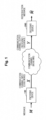
- Fig. 1 illustrates a configuration example of a communication system in the present embodiment.
- Fig. 1 illustrates an example in which the present invention is applied to a communication channel code (error correction code).
- the communication system includes an encoding device 100 and a decoding device 200, which are connected by a communication channel.
- the encoding device may be referred to as an encoder or the like.
- the decoding device may be referred to as a decoder or the like.
- the encoding device 100 encodes an input message M with a polar code, and outputs a code word X as a communication channel input.
- the decoding device 200 receives Y, which is a communication channel output in which noise is mixed into the code word, performs polar code decoding processing, and outputs a reproduction message ⁇ M.
- the decoding device 200 performs decoding by a successive cancellation decoding method or a successive cancellation list decoding method.
- the successive cancellation decoding method is a method of sequentially decoding bits of a message one by one.
- the successive cancellation list decoding method is a method in which, when the bits are decoded, L sequences (L is a list size) having high likelihood are set as survival paths, and only the maximum likelihood sequence is finally output as a decoding result.
- L is a list size
- the processing (algorithm) of the decoding device 200 will be described in detail later.
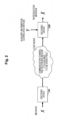
- Fig. 2 is a system configuration diagram in a case where the present invention is applied to an information source code (information compression code).
- auxiliary information is, for example, information of a frame preceding a frame to be decoded in a video.
- the auxiliary information Y may be input to the decoding device 200 from the outside, or may be stored in the decoding device 200 in advance, or a past decoding result may be used as the auxiliary information.
- Fig. 3 is a functional configuration diagram of the decoding device 200.
- the decoding device 200 includes an input unit 210, a computation unit 220, an output unit 230, and a data storage unit 240.
- the input unit 210 inputs information from a communication channel or a recording medium, or the like.
- the computation unit 220 executes an algorithm related to the decoding processing.
- the output unit 230 outputs a computation result (for example, a reproduction message) obtained by the computation unit 220.
- the data storage unit 240 corresponds to a memory referenced by an algorithm of the decoding processing executed by the computation unit 220.
- the data storage unit 240 stores known information and the like used for processing.
- an “algorithm” may also be called a “processing procedure”, a “program”, “software”, or the like.
- the decoding device 200 can be implemented, for example, by causing a computer to execute a program in which processing contents described in the present embodiment are described.
- the "computer” may be a physical machine or a virtual machine on a cloud.
- "hardware” described herein is virtual hardware.
- the above program can be stored and distributed by having it recorded on a computer-readable recording medium (portable memory or the like). Furthermore, the above program can also be provided through a network such as the Internet or e-mail.
- Fig. 4 is a diagram illustrating a hardware configuration example of the computer.
- the computer in Fig. 4 includes a drive device 1000, an auxiliary storage device 1002, a memory device 1003, a CPU 1004, an interface device 1005, a display device 1006, an input device 1007, an output device 1008, and the like which are connected to each other by a bus B.
- the program for implementing the processing in the computer is provided by, for example, a recording medium 1001 such as a CD-ROM or a memory card.
- a recording medium 1001 such as a CD-ROM or a memory card.
- the program is installed from the recording medium 1001 to the auxiliary storage device 1002 via the drive device 1000.
- the program is not necessarily installed from the recording medium 1001, and may be downloaded from another computer via a network.
- the auxiliary storage device 1002 stores the installed program and also stores necessary files, data, and the like.
- the memory device 1003 reads and stores the program from the auxiliary storage device 1002.
- the CPU 1004 implements a function related to the decoding device 200 in accordance with a program stored in the memory device 1003.
- the interface device 1005 is used as an interface for connecting to the network.
- the display device 1006 displays a graphical user interface (GUI) or the like by the program.
- the input device 1007 includes a keyboard and mouse, buttons, a touch panel, or the like, and is used to input various operation instructions.
- the output device 1008 outputs a computation result. Note that the display device 1006 and the input device 1007 may not be provided.
- Reference Literature is indicated as [1], [2], and the like.
- the names of the Reference Literature are described at the end of the specification.
- the polar information source code/communication channel code is introduced in Arikan [1], [2], and [3], and Arikan proposes a successive cancellation decoding method that can be implemented with a calculation amount O (Nlog 2 N) with respect to a block length N.
- the technique according to the present embodiment can be applied to both the polar information source code and the polar communication channel code. Furthermore, the decoding algorithm in the present embodiment can reduce the memory amount and the calculation amount as compared with the conventional technique such as [9] .
- n is given as a constant, and all the algorithms of the present embodiment can refer to this n.
- bit indexing introduced in [1] is used.
- 0 n and 1" represent n-bit all-0 sequences and all-1 sequences, respectively. To represent integer intervals, the following notations are used.
- a subsequence of X N is defined as follows.
- X I X b n b n ⁇ I
- c l b k ⁇ 0,1 ⁇ l+k is a concatenation of b k ⁇ 0,1 ⁇ k and c l ⁇ 0,1 ⁇ l .
- a symbol on the right shoulder of the matrix represent the n-th Kronecker product and ⁇ BR is the bit inverted permutation matrix [1].
- P U I 0 U I 1 Y of U I 0 U I 1 Y using a joint distribution P XY of (X,Y), P U I 0 U I 1 Y u I 0 u I 1 y P XY u I 1 u I 0 G ⁇ 1 , y is defined.
- u_I 1 ,u_I 0 the elements of (u_I 1 ,u_I 0 ) are sorted in the order of indices before the processing of G -1 .
- u_I 1 and u_I 0 are referred to as a frozen bit and a non-frozen bit, respectively.
- U 0 n : b n Y is a conditional probability distribution defined as follows.
- u 0 n : b n , y ⁇ u b n : 1 n P U I 0 U I 1 Y u I 0 u I 1 y ⁇ u b n : 1 n P U I 0 U I 1 Y u I 0 u I 1 y
- x ⁇ 0,1 ⁇ N is an information source output
- u_I 1 is a code word
- y ⁇ Y N is an auxiliary information source output.
- the decoder reproduces the information source output f(u_I 1 ,y)G -1 from code words u_I 1 and y.
- the (block) decoding error probability is given as Prob (f(U_I 1 ,Y)G -1 ⁇ X).
- the elements of (x_I 1 ',x_I 0 ') and (u_I 1 ,u_I 0 ) are sorted in the order of indices before the operation of G -1 .
- the elements of (x_I 0 ', x_I 1 ') are sorted in the order of indices.
- ⁇ x_I 0 ' is reproduction of the message.
- the (block) decoding error probability is also given as Prob (f(U_I 1 ,Y)G -1 ⁇ X).
- u_I 0 is a message, and a vector u_I 1 is shared by an encoder and a decoder.
- the elements of (u_I 1 ,u_I 0 ) are rearranged in the order of indices before G -1 is operated.
- ⁇ u_I 0 is reproduction of the message.
- the (block) decoding error probability is given as Prob(f(U_I 1 ,Y) ⁇ (U_I 0 ,U_I 1 )).
- Lemma 1 ([2, Theorem 2], [7, Theorem 4.10]):I 0 is defined as follows.
- I 0 b n ⁇ 0 n : 1 n : Z U b n
- Z is a function [2] that gives a Battacharyya parameter.
- lim n ⁇ ⁇ I 0 2 n 1 ⁇ H X
- Y lim n ⁇ ⁇ I 1 2 n H X
- Y are obtained.
- I 0 can be obtained by using a technique introduced in [8]. In the following, it is assumed that any I 0 is given.
- ⁇ u is the bipolar binary conversion of u.
- notations of the algorithm illustrated in each drawing are general by themselves. For example, “for A do B” means executing B on each element defined by A. "if C then D else E” means that D is executed in a case where the condition C is satisfied (in a case of true), and E is executed in a case where the condition is not satisfied.
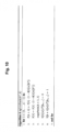
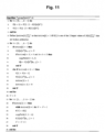
- the decoding device 200 performs decoding processing of the polar code by executing Algorithm 1 of successive cancellation decoding illustrated in Fig. 5 .
- This algorithm is based on a technique introduced in [9]. Processing contents of update ⁇ ( ⁇ ,U,n,b n ) in line 3 of Algorithm 1 are illustrated in Fig. 6 as Algorithm 2. In addition, processing contents of updateU(U,n,b n-1 ) in line 9 of Algorithm 1 are illustrated in Fig. 7 as Algorithm 3.
- each element of ⁇ is a conditional probability of 0 and 1 expressed by one parameter by applying the symmetric parameterization, and corresponds to a conditional probability expressing how much the value of the bit to be decoded deviates from 1/2.
- This ⁇ is updated by update ⁇ ( ⁇ ,U,n,b n ).
- the computation unit 220 that executes Algorithms 1 to 3 can access (refer to) the number n of times of polar conversion, the frozen bit u (n) _I 1 , and the following memory space.
- the memory space corresponds to the data storage unit 240 of the decoding device 200. The successive cancellation decoding processing executed by Algorithms 1 to 3 will be described below.
- ⁇ [k][c n-k ] is a real variable
- U[k][c n-k ][b] is a binary variable
- P U c n 0 c n ⁇ 0 n : 1 n is given depending on the context.
- U c n 0 c n ⁇ 0 n : 1 n is allowed to be a non-steady state.
- U (n) _b n is recursively defined (calculated) as [Math. 36]
- U c n ⁇ k b k ⁇ 1 1 k U c n ⁇ k 1 b k ⁇ 1 k ⁇ 1 for a certain b n ⁇ 0,1 ⁇ n and c n-k ⁇ 0,1 ⁇ n-k .
- the purpose of updateU(U,n,b n-1 ) in line 9 of Algorithm 1 is to calculate u (k) _c n-k b k-1 0 from u (n) [0 n :b n-1 0] using the relation of [Math.
- Formulas (20) and (21) are obtained from Formulas (13) and (14).
- u (n) _[0 n :b n-1 0] is normally decoded.
- Formulas (18) and (19) correspond to lines 5 and 7 of Algorithm 2, respectively, and formulas (20) and (21) correspond to lines 2 and 3 of Algorithm 3, respectively.
- line 7 of Algorithm 1 corresponds to a maximum posterior probability discrimination defined as follows.
- u ⁇ b n arg max u ⁇ 0,1 P U b n n
- Algorithm 1 is used for a decoder of a systematic polar communication channel code in which the communication channel output vector y_[0 n :1 n ] and the shared vector u (n) _I 1 are used as inputs, with respect to a given communication channel distribution P Y c n
- Algorithm 1 In a case where Algorithm 1 is applied to a decoder of a non-systematic polar communication channel code, a series of binary variables ⁇ M[b n ] ⁇ _b n ⁇ I 0 is prepared, and immediately after U[n][c 0 ][b n-1 ] (line 7 of Algorithm 1) is updated, M b n ⁇ U n c 0 b n ⁇ 1 is inserted. Algorithm 1 with this modification is shown in Fig. 20 .
- a fixed address memory space is used instead of using the stacking memory space in [9].
- the calculation amount of the algorithm according to the present embodiment is approximately half of that introduced in [9].
- the decoding device 200 performs decoding processing of the polar code by executing Algorithm 4 of successive cancellation decoding illustrated in Fig. 8 .
- Processing contents of update ⁇ ( ⁇ [ ⁇ ],U,[ ⁇ ],n,b n ) in line 5 of Algorithm 4 are illustrated in Fig. 6 as Algorithm 2.
- Processing contents of extendPath(b n , ⁇ ) in line 7 of Algorithm 4 are illustrated in Fig. 9 as Algorithm 5.
- Processing contents of splitPath(b n , ⁇ ) in line 10 of Algorithm 4 is illustrated in Fig. 10 as Algorithm 6.
- Processing contents of prunePath(b",A) in line 13 of Algorithm 4 is illustrated in Fig. 11 as Algorithm 7.
- Processing contents of copyPath( ⁇ ',A-A) in line 25 of Algorithm 7 is illustrated in Fig. 12 as Algorithm 8. Processing contents of magnifyP(A) in line 17 of Algorithm 4 is illustrated in Fig. 13 as Algorithm 9. Processing contents of updatedU(U[ ⁇ ],n,b n-1 ) in line 19 of Algorithm 4 is illustrated in Fig. 7 as Algorithm 3.
- the memory space corresponds to the data storage unit 240.
- ⁇ [ ⁇ ] and U[ ⁇ ] are calculated in Algorithms 2 and 3.
- l in Formula (30) is the most probable path (sequence).
- the binary variable M ⁇ b n ⁇ ⁇ 0 , ... L ⁇ 1 , b n ⁇ I 0 is prepared, and immediately after U[ ⁇ ] [n] [c 0 ][b n-1 ] and U[ ⁇ + ⁇ ][n][c 0 ][b n-1] are updated (lines 5 and 6 of Algorithm 6, lines 8, 11, 15, and 26 of Algorithm 7), respectively, M ⁇ b n ⁇ U ⁇ n c 0 b n ⁇ 1 M ⁇ + ⁇ b n ⁇ U ⁇ + ⁇ n c 0 b n ⁇ 1 is inserted.
- u ⁇ b n l M l b n is defined, and reproduction u ⁇ b n l b n ⁇ I 0 is obtained.
- l is a maximum likelihood sequence defined by Formula (30).
- the modified Algorithm 6 is shown in Fig. 21
- the modified algorithm 7 is shown in Fig. 22 .
- Fig. 23 illustrates Algorithm 4 after skip processing of Remark 2 and omission of Remark 3 with respect to Algorithm 4.
- Algorithm 7 after omission of Remark 3 with respect to Algorithm 7 is illustrated in Fig. 24 . Note that line 9 of Algorithm 4 in Fig. 23 corresponds to skip processing of Remark 2 with respect to Algorithm 5 in Fig.
- Fig. 25 illustrates a modification when Algorithm 7 illustrated in Fig. 24 is applied to the non-systematic communication channel code.
- the binary representation b k ⁇ [0 k :1 k ] may be represented by a corresponding integer in ⁇ 0,...,2 k -1 ⁇ . It is assumed that i(b k ) is the corresponding integer of b k .
- b k-1 is used for a given b k .
- b k-1 can be obtained by using a 1-bit right shift of b k .
- floor is a function that outputs an integer value obtained by rounding down decimal places with respect to an input of a real number.
- c n-k 0 can be obtained by setting the least significant bit of c n-k 0 to 1 and using c n-k and a 1-bit left shift of c n-k 1.
- the corresponding integer can be obtained using the following relational expression.
- Fig. 14 illustrates Algorithm 2.
- ⁇ [k][c n-k ] is represented by a 3-bit signed integer including a sign bit and two bits representing an absolute value.
- Fig. 15 illustrates Algorithm 2.
- Algorithm 2 In this Algorithm 2,
- ⁇ k c n ⁇ k ⁇ ⁇ k c n ⁇ k
- ⁇ 1 k c n ⁇ k is a 2-bit signed integer including a sign bit ⁇ ⁇ k c n ⁇ k and two bits representing an absolute value bit ⁇ 1 [k][c n-k ].
- ⁇ represents an AND computation
- ⁇ represents an OR computation
- ⁇ represents an XOR computation
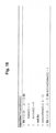
- line 5 of Algorithm 7 can be implemented by Algorithm 7-1 (markPath(X)) illustrated in Fig. 16 .
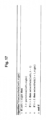
- the algorithm of selectPath(0,2 ⁇ -1) in line 5 in Algorithm 7-1 is shown in Fig. 17 as Algorithm 7-2.
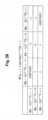
- the algorithm of partition(left,right) on line 2 in Algorithm 7-2 is shown in Fig. 18 as Algorithm 7-3.
- the algorithm of swapIndex in Algorithm 7-3 is shown in Fig. 19 as Algorithm 7-4.
- Index[ ⁇ ] ⁇ 0,...2L-1 ⁇ is an integer variable.
- the time complexity of sorting is O( ⁇ log ⁇ ), but in a case where ⁇ is small, the time complexity may be faster than selectPath(0,2 ⁇ -1).
- the input information described below is input from the input unit 210 in the decoding device 200 shown in Fig. 3 , stored in the data storage unit 240, and referred to by the computation unit 220 that executes the algorithm.
- Reference to information by the computation unit 220 that executes the algorithm may be expressed as input of information to the algorithm.
- a computation result by the computation unit 220 is output to and stored in the data storage unit 240.
- the computation result (original message) is read from the data storage unit 240 by the computation unit 220 and output from the output unit 230.
- the input to Algorithm 1 is as follows.
- the code word in the case of the information source code is more specifically as follows.
- the communication channel input for the systematic communication channel code is more specifically as follows.
- the encoding device 100 sets x_I 0 ' as a message vector and u (0) _I 1 as information shared by the encoding device 100 and the decoding device 200 (for example, all are set to 0). Then, a known polar code algorithm is applied to obtain (x_I 1 ',u_I 0 ) from (x_I 0 ',u_I 1 ).
- a known polar code algorithm is applied to obtain (x_I 1 ',u_I 0 ) from (x_I 0 ',u_I 1 ).
- the relationship of I 0 , I 1 , I 0 ', and I 1 ' is defined by the above-described Formulas (1) and (2).
- the communication channel input also referred to as a code word
- the communication channel input that is the output of encoding device 100 is obtained by aligning (x_I 0 ',x_I 1 ') in the order of indices.
- the communication channel input for the non-systematic communication channel code is more specifically as follows.
- the encoding device 100 sets u (0) _I 0 as a message vector and u (0) _I 1 as information shared by the encoding device 100 and the decoding device 200 (for example, all are set to 0).
- u lsb n b n _ b n ⁇ 0 n : 1 n is obtained and set as a communication channel input (also referred to as a code word) which is an output of the encoding device 100.
- the output from Algorithm 1 is stored in the memory space shown in [Math. 30].
- the reproduction information as the decoding result is obtained by the following interpretation depending on the object to be applied.
- the input to Algorithm 2 is as follows.
- the output from Algorithm 4 is stored in the memory spaces (memory areas) of ⁇ , U, and P as described above. Specifically, this is as follows. ⁇ ⁇ 0 , ... , L ⁇ ⁇ k c n ⁇ k : k ⁇ 0 , ... , n c n ⁇ k ⁇ 0 n ⁇ k : 1 n ⁇ k ⁇ ⁇ 0 , ... , L k ⁇ 0 , ... , n U ⁇ k c n ⁇ k b : c n ⁇ k ⁇ 0 n ⁇ k : 1 n ⁇ k b ⁇ 0,1 P ⁇ : ⁇ ⁇ 0 , ... , L
- the reproduction information as the decoding result is obtained by the following interpretation depending on the object to be applied.
- Algorithm 8 is an algorithm corresponding to copyPath( ⁇ ', ⁇ ) in line 4 of Algorithm 6 ( Fig. 10 ) and lines 10 and 25 of Algorithm 7 ( Fig. 11 ), and implements a function of copying the state of the Xth list to a memory that stores the state of the ⁇ 'th list.
- the algorithm 9 is an algorithm that implements rewriting of content of the above memory P (setting the maximum value to 1 without change of ratio of real number stored in memory).
- Algorithm 2 illustrated in Figs. 14 and 15 is an algorithm that speeds up Algorithm 2 when Algorithm 1 is applied to a polar code for an erasure channel.
- the input/output is the same as that of Algorithm 2.
- Algorithm 4 and Algorithm 7 in a case where it is assumed that the set I 0 is not an empty set, L is a power of 2, and only a real number computation with finite accuracy is possible (although not realistic, in the case of infinite accuracy, line 27 of algorithm 4 in Fig. 23 can be deleted) are as shown in Figs. 23 to 25 . Note that, in a case where I 0 is an empty set, L 1 is set, and the processing up to lines 5 to 8 of Algorithm 4 illustrated in Fig. 23 is skipped and the processing up to line 14 is finished.
- the value ⁇ [k][c n-k ] takes any value of ⁇ -1,0,1 ⁇ .
- ⁇ [ ⁇ ][k][c n-k ] can be a variable having a value of ⁇ -1,0,1 ⁇
- the division can be omitted by using Algorithm 2 illustrated in Fig. 14 instead of Algorithm 2 in Fig. 6 . Since carrying-up occurs, three bits including a sign are required for ⁇ [k][c n-k ].
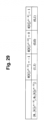
- ⁇ [k][c n-k ] is represented as illustrated in Fig. 29 .
- ⁇ _ k c n ⁇ k , ⁇ 1 k c n ⁇ k may also be encoded with two bits.
- Figs. 30 to 32 may be implemented in lines 4 to 8 of Algorithm 2.
- ⁇ k c n ⁇ k ⁇ _ k c n ⁇ k , ⁇ 1 k c n ⁇ k is interpreted as a 2-bit signed integer of a sign part 1-bit and a numerical part 1-bit.
- a stack memory is used in the processing of the conventional method, but a memory space having a fixed address is directly operated in the proposed method.
- the operation in the conventional method regarding the stack memory is simplified in the proposed method.
- a decoding device including:
- the decoding device according to any one of clauses 1 to 5, in which the computation unit executes list decoding for selecting a sequence of a most probable path from among the number (predetermined list size) of survival paths.
- a decoding method executed by a decoding device including:
Landscapes
- Engineering & Computer Science (AREA)
- Physics & Mathematics (AREA)
- Probability & Statistics with Applications (AREA)
- Theoretical Computer Science (AREA)
- Computer Networks & Wireless Communication (AREA)
- Signal Processing (AREA)
- Error Detection And Correction (AREA)
Abstract
Description
- The present invention relates to a technique for decoding information encoded by a polar code.
- The polar code proposed by Arikan is a code that can implement characteristics asymptotically approaching the Shannon limit by using communication channel polarization, and is used for communication channel encoding in 5G, for example.
- Further, as a method of decoding a code word encoded by a polar code, there are a successive cancellation decoding method, a successive cancellation list decoding method, and the like. The successive cancellation decoding method is a method of sequentially decoding bits of a message one by one. The successive cancellation list decoding method is a method in which, when the bits are decoded, L sequences (L is a list size) having high likelihood are set as survival paths, and only the most probable sequence is finally output as a decoding result.
-
- Non-Patent Literature 1: I. Tal, A. Vardy, "List decoding of polar codes, "IEEE Transactions on Information Theory, vol. 61, no. 5, May 2015.
- Non-Patent Literature 2: E.Arikan, et al. "Source polarization, "Proc. 2010IEEE International Symposium on Information Theory, 2010, pp. 899-903.
- As a conventional technique of decoding a polar code, for example, there is a technique disclosed in Non-Patent
Literature 1 and the like. However, in the conventional technique disclosed in Non-PatentLiterature 1 and the like, there is a problem that the memory amount used in the decoding processing increases. When the used memory amount increases, for example, the calculation amount (calculation time) related to processing, such as copying states of candidates in list decoding, also increases. - The present invention has been made in view of the above points, and an object thereof is to provide a technique capable of reducing the memory amount in decoding of a polar code.
- According to the disclosed technique, a decoding device is provided that includes: an input unit that inputs a code word encoded by a polar code from an original message; a computation unit that decodes the original message from the code word based on a conditional probability expressed by a symmetric parameterization and having observation information as a condition; and an output unit that outputs the decoded original message.
- According to the disclosed techniques, a technique capable of reducing a memory amount in decoding of a polar code is provided.
-
-
Fig. 1 is a configuration diagram illustrating a communication system according to an embodiment of the present invention. -
Fig. 2 is a configuration diagram illustrating the communication system according to the embodiment of the present invention. -
Fig. 3 is a configuration diagram of a decoding device. -
Fig. 4 is a hardware configuration diagram of the decoding device. -
Fig. 5 is adiagram illustrating Algorithm 1. -
Fig. 6 is adiagram illustrating Algorithm 2. -
Fig. 7 is adiagram illustrating Algorithm 3. -
Fig. 8 is adiagram illustrating Algorithm 4. -
Fig. 9 is adiagram illustrating Algorithm 5. -
Fig. 10 is adiagram illustrating Algorithm 6. -
Fig. 11 is adiagram illustrating Algorithm 7. -
Fig. 12 is adiagram illustrating Algorithm 8. -
Fig. 13 is adiagram illustrating Algorithm 9. -
Fig. 14 is adiagram illustrating Algorithm 2. -
Fig. 15 is adiagram illustrating Algorithm 2. -
Fig. 16 is a diagram illustrating Algorithm 7-1. -
Fig. 17 is a diagram illustrating Algorithm 7-2. -
Fig. 18 is a diagram illustrating Algorithm 7-3. -
Fig. 19 is a diagram illustrating Algorithm 7-4. -
Fig. 20 is adiagram illustrating Algorithm 1. -
Fig. 21 is adiagram illustrating Algorithm 6. -
Fig. 22 is adiagram illustrating Algorithm 7. -
Fig. 23 is adiagram illustrating Algorithm 4. -
Fig. 24 is adiagram illustrating Algorithm 7. -
Fig. 25 is adiagram illustrating Algorithm 7. -
Fig. 26 is a diagram illustrating a table used for application to an erasure channel. -
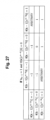
Fig. 27 is a diagram illustrating a table used for application to the erasure channel. -
Fig. 28 is a diagram illustrating a table used for application to the erasure channel. -
Fig. 29 is a diagram illustrating a table used for application to the erasure channel. -
Fig. 30 is a diagram illustrating a table used for application to the erasure channel. -
Fig. 31 is a diagram illustrating a table used for application to the erasure channel. -
Fig. 32 is a diagram illustrating a table used for application to the erasure channel. -
Fig. 33 is adiagram illustrating Algorithm 1. - Hereinafter, embodiments of the present invention (present embodiments) will be described with reference to the drawings. The embodiments described below are merely examples, and embodiments to which the present invention is applied are not limited to the following embodiments.
- Note that, in the text of the main body of the present description, a hat "^" will be added to the head of characters for convenience of description. "^M" is an example. Furthermore, in the text of the main body of the present specification, in a case where a superscript or a subscript C is used for a subscript B of a certain character A, the subscript B of the character A is not represented by a subscript but is represented by using "_" as in A_BC.
-
Fig. 1 illustrates a configuration example of a communication system in the present embodiment.Fig. 1 illustrates an example in which the present invention is applied to a communication channel code (error correction code). As illustrated inFig. 1 , the communication system includes anencoding device 100 and adecoding device 200, which are connected by a communication channel. Note that the encoding device may be referred to as an encoder or the like. The decoding device may be referred to as a decoder or the like. - In the present embodiment, the
encoding device 100 encodes an input message M with a polar code, and outputs a code word X as a communication channel input. Thedecoding device 200 receives Y, which is a communication channel output in which noise is mixed into the code word, performs polar code decoding processing, and outputs a reproduction message ^M. As will be described later, thedecoding device 200 performs decoding by a successive cancellation decoding method or a successive cancellation list decoding method. The successive cancellation decoding method is a method of sequentially decoding bits of a message one by one. The successive cancellation list decoding method is a method in which, when the bits are decoded, L sequences (L is a list size) having high likelihood are set as survival paths, and only the maximum likelihood sequence is finally output as a decoding result. The processing (algorithm) of thedecoding device 200 will be described in detail later. - The decoding algorithm in the present embodiment can uniformly handle decoding of a communication channel code and decoding of an information source code.
Fig. 2 is a system configuration diagram in a case where the present invention is applied to an information source code (information compression code). - In the configuration illustrated in
Fig. 2 , it is assumed that theencoding device 100 and thedecoding device 200 are connected by a noise-free communication channel or information is exchanged by a noise-free storage medium. X is input to theencoding device 100 as a message, and a code word is output from theencoding device 100 after being encoded by a polar code. The code word and auxiliary information Y correlated with X are input to thedecoding device 100. Thedecoding device 100 performs polar code decoding processing and outputs a reproduction message ^M. The auxiliary information is, for example, information of a frame preceding a frame to be decoded in a video. Note that the auxiliary information Y may be input to thedecoding device 200 from the outside, or may be stored in thedecoding device 200 in advance, or a past decoding result may be used as the auxiliary information. -
Fig. 3 is a functional configuration diagram of thedecoding device 200. As illustrated inFig. 3 , thedecoding device 200 includes aninput unit 210, acomputation unit 220, anoutput unit 230, and adata storage unit 240. Theinput unit 210 inputs information from a communication channel or a recording medium, or the like. Thecomputation unit 220 executes an algorithm related to the decoding processing. Theoutput unit 230 outputs a computation result (for example, a reproduction message) obtained by thecomputation unit 220. Thedata storage unit 240 corresponds to a memory referenced by an algorithm of the decoding processing executed by thecomputation unit 220. In addition, thedata storage unit 240 stores known information and the like used for processing. - In the present embodiment, an "algorithm" may also be called a "processing procedure", a "program", "software", or the like.
- The
decoding device 200 according to the present embodiment can be implemented, for example, by causing a computer to execute a program in which processing contents described in the present embodiment are described. Note that the "computer" may be a physical machine or a virtual machine on a cloud. In a case where a virtual machine is used, "hardware" described herein is virtual hardware. - The above program can be stored and distributed by having it recorded on a computer-readable recording medium (portable memory or the like). Furthermore, the above program can also be provided through a network such as the Internet or e-mail.
-
Fig. 4 is a diagram illustrating a hardware configuration example of the computer. The computer inFig. 4 includes adrive device 1000, anauxiliary storage device 1002, amemory device 1003, aCPU 1004, aninterface device 1005, adisplay device 1006, aninput device 1007, anoutput device 1008, and the like which are connected to each other by a bus B. - The program for implementing the processing in the computer is provided by, for example, a
recording medium 1001 such as a CD-ROM or a memory card. When therecording medium 1001 storing the program is set in thedrive device 1000, the program is installed from therecording medium 1001 to theauxiliary storage device 1002 via thedrive device 1000. However, the program is not necessarily installed from therecording medium 1001, and may be downloaded from another computer via a network. Theauxiliary storage device 1002 stores the installed program and also stores necessary files, data, and the like. - In a case where an instruction to start the program is made, the
memory device 1003 reads and stores the program from theauxiliary storage device 1002. TheCPU 1004 implements a function related to thedecoding device 200 in accordance with a program stored in thememory device 1003. Theinterface device 1005 is used as an interface for connecting to the network. Thedisplay device 1006 displays a graphical user interface (GUI) or the like by the program. Theinput device 1007 includes a keyboard and mouse, buttons, a touch panel, or the like, and is used to input various operation instructions. Theoutput device 1008 outputs a computation result. Note that thedisplay device 1006 and theinput device 1007 may not be provided. - Hereinafter, algorithms (corresponding to the above program) executed by the
decoding device 200 will be described in detail. Hereinafter, first, definitions and basic related techniques will be described, and then each algorithm will be described. In the following description, Reference Literature is indicated as [1], [2], and the like. The names of the Reference Literature are described at the end of the specification. Note that the polar information source code/communication channel code is introduced in Arikan [1], [2], and [3], and Arikan proposes a successive cancellation decoding method that can be implemented with a calculation amount O (Nlog2N) with respect to a block length N. - In the present embodiment, an algorithm of the successive cancellation decoding method and an algorithm for the successive cancellation list decoding method based on what is introduced in Tal and Vardy [9] will be described. As described above, the technique according to the present embodiment can be applied to both the polar information source code and the polar communication channel code. Furthermore, the decoding algorithm in the present embodiment can reduce the memory amount and the calculation amount as compared with the conventional technique such as [9] .
- In the description of the algorithm of the present embodiment, the following definitions and notations will be used.
- For a certain n, N=2n indicates a block length. n is given as a constant, and all the algorithms of the present embodiment can refer to this n. In the present embodiment, bit indexing introduced in [1] is used. The index of the N-dimensional vector can be expressed as XN=(X_0n,...,X_1n) as a set of n-bit strings. Here, 0n and 1" represent n-bit all-0 sequences and all-1 sequences, respectively. To represent integer intervals, the following notations are used.

- For a certain subset I of [0n:1n], a subsequence of XN is defined as follows.

- It is assumed that clbk∈{0,1}l+k is a concatenation of bk∈{0,1}k and cl∈{0,1}l. For a given bk∈{0,1}k and cl∈{0,1}l, subsets of cl[0:bk] and cl[0:bk) of {0,1}k+l can be defined as


-


- Here, the binary polar information source/communication channel code introduced in the existing techniques [1], [2], [3], and [7] will be described. It is assumed that {0,1} is a body having a characteristic of 2. For a given positive integer n, polar conversion G is defined as follows.

- Here, a symbol on the right shoulder of the matrix represent the n-th Kronecker product and ΠBR is the bit inverted permutation matrix [1]. A vector u∈{0,1}N is then defined as u=xG for a given vector x∈{0,1}N. It is assumed that {I0,I1} is a division of [0n:1n], and I0∩I1=φ and I0∪I1=[0n:1n] are satisfied. {I0,I1} will be defined later.
- It is assumed that X=(X_0n,...,X_1n) and Y=(Y_0n,...,Y_1n) are random variables, and U=(U_0n,...,U_1n) is a random variable defined as U=XG.
-


- In the above formula, the elements of (u_I1,u_I0) are sorted in the order of indices before the processing of G-1. u_I1 and u_I0 are referred to as a frozen bit and a non-frozen bit, respectively.
- It is assumed that


- For the vector u_I1 and the auxiliary information y∈yN, a successive cancellation (SC) decoder f that outputs ^u=f(u_I1,y) is recursively defined as

- The set of functions {f_bn}_bn∈I0 used in the above formula is defined as

- In the case of a polar information source code (with auxiliary information), x∈{0,1}N is an information source output, u_I1 is a code word, and y∈YN is an auxiliary information source output. The decoder reproduces the information source output f(u_I1,y)G-1 from code words u_I1 and y. The (block) decoding error probability is given as Prob (f(U_I1,Y)G-1≠X).
- In the systematic polar communication channel code [3], I0'and I1' for a given (I0,I1) are defined as follows.
[Math. 12]

- It is assumed that the encoder and the decoder share a vector u_I1. The encoder calculates (x_I1',u_I0) satisfying (x_I1',x_I0')=(u_I1,u_I0)G-1 from a message x_I0' and the shared vector u_I1. Here, the elements of (x_I1',x_I0') and (u_I1,u_I0) are sorted in the order of indices before the operation of G-1.
- The encoder generates a communication channel input x=(x_I0',x_I1') . Here, the elements of (x_I0', x_I1') are sorted in the order of indices. The decoder reproduces the communication channel input ^x=f(u_I1,y)G-1 from the communication channel output y∈yN and the shared vector u_I1. ^x_I0' is reproduction of the message. The (block) decoding error probability is also given as Prob (f(U_I1,Y)G-1≠X).
- In a non-systematic polar communication channel code, u_I0 is a message, and a vector u_I1 is shared by an encoder and a decoder. The encoder generates a communication channel input x∈{0,1}N with x=(u_I1,u_I0)G-1. Here, the elements of (u_I1,u_I0) are rearranged in the order of indices before G-1 is operated. The decoder generates a pair of vectors (u_I1,^u_I0)=f(u_I1,y) from the communication channel output y∈yN and the shared vector u_I1. Then, ^u_I0 is reproduction of the message. The (block) decoding error probability is given as Prob(f(U_I1,Y)≠(U_I0,U_I1)).
- Lemmas will be described below.
- Lemma 1 ([2, Theorem 2], [7, Theorem 4.10]):I0 is defined as follows.


- There is the following lemma which can be proven as in the previous proof [1].
- Lemma 2 ([6, Lemma 2], [8, Formula (1)], [7, Proposition 2.7]):

- From the above lemma, a fact is obtained that the rate of the polar code reaches the fundamental limit, and the decoding error probability becomes zero with n→∞. For example, I0 can be obtained by using a technique introduced in [8]. In the following, it is assumed that any I0 is given.
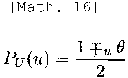
- Here, a polar conversion based on the symmetric parameterization used in the expression of the conditional probability in the present embodiment will be described. For a given probability distribution Pu of a binary random variable U, θ is defined as follows.


- In the basic polar conversion, a pair of binary random variables (U0,U1) is converted as follows.
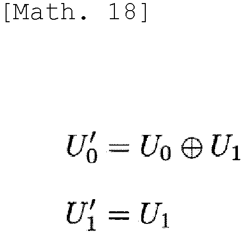

characteristic 2. It is assumed that the random variables U0,U1∈{0,1} are independent. For each i∈{0,1}, θi is defined as follows.
- Here, the following equalities are obtained.
[Math. 21]
- The first equality is obtained from the definition of U0' and the fact that U0 and U1 are independent of each other.
- Furthermore, the following equalities are obtained.
[Math. 22]
- From Formula (3) and Formula (4),
[Math. 23]
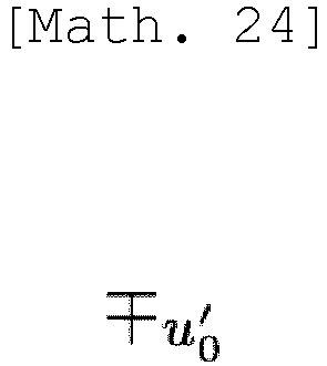
[Math. 25]
- From Formula (3) to Formula (6),

- Since the symmetric parameterization is a binary version of the Fourier transform of a probability distribution [5,
Definitions 24 and 25], the right side of Formula (7) corresponds to the Fourier transform of the convolution. - Here,
[Math. 26]
[Math. 27]

- θ1' is defined as follows.
[Math. 28]
- From Formula (9) to Formula (11),
[Math. 29]
- Next, an algorithm of successive cancellation decoding executed by the
decoding device 200 according to the present embodiment will be described. - Note that, in the present embodiment, notations of the algorithm illustrated in each drawing are general by themselves. For example, "for A do B" means executing B on each element defined by A. "if C then D else E" means that D is executed in a case where the condition C is satisfied (in a case of true), and E is executed in a case where the condition is not satisfied.
- The
decoding device 200 performs decoding processing of the polar code by executingAlgorithm 1 of successive cancellation decoding illustrated inFig. 5 . This algorithm is based on a technique introduced in [9]. Processing contents of updateΘ(Θ,U,n,bn) inline 3 ofAlgorithm 1 are illustrated inFig. 6 asAlgorithm 2. In addition, processing contents of updateU(U,n,bn-1) inline 9 ofAlgorithm 1 are illustrated inFig. 7 asAlgorithm 3. - Here, each element of Θ is a conditional probability of 0 and 1 expressed by one parameter by applying the symmetric parameterization, and corresponds to a conditional probability expressing how much the value of the bit to be decoded deviates from 1/2. This Θ is updated by updateΘ(Θ,U,n,bn).
- As illustrated in
line 7 ofAlgorithm 1, whether the value of the bit is 0 or 1 is determined by comparing Θ[n][0] and 0. Note that "0 or 1" inline 7 ofAlgorithm 1 indicates that the value of the bit may be either 0 or 1. - The
computation unit 220 that executesAlgorithms 1 to 3 can access (refer to) the number n of times of polar conversion, the frozen bit u(n)_I1, and the following memory space. The memory space corresponds to thedata storage unit 240 of thedecoding device 200. The successive cancellation decoding processing executed byAlgorithms 1 to 3 will be described below.
- In the above formula, Θ[k][cn-k] is a real variable, U[k][cn-k][b] is a binary variable, and c0 is a null character string. Note that Θ has
Σ n k=02n-k=2n+1-1 variables, and U has2Σ n k=02n-k=2n+2-2 variables. - In the following,

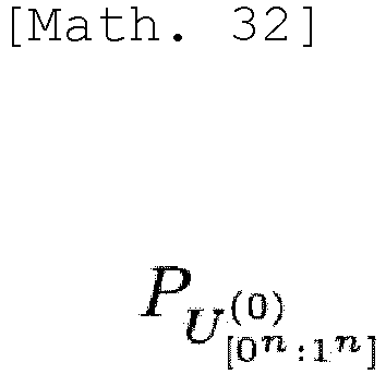

where


- U(n)_bn is recursively defined (calculated) as
[Math. 36]

- At this time,

line 3 ofAlgorithm 1 starts from the following Formula (16), and
[Math. 38]
[Math. 39]
- Processing contents of updateΘ(Θ,U,n,bn) in
line 3 inAlgorithm 1 are shown. InAlgorithm 2 ofFig. 6 ,
parameters defined as [Math. 40]
[Math. 41]


line 9 ofAlgorithm 1 is to calculate u(k)_cn-kbk-10 from u(n)[0n:bn-10] using the relation of
[Math. 43]

- Formulas (20) and (21) are obtained from Formulas (13) and (14). Here, it is assumed that u(n)_[0n:bn-10] is normally decoded.
- Formulas (18) and (19) correspond to
lines Algorithm 2, respectively, and formulas (20) and (21) correspond tolines Algorithm 3, respectively. - After applying
lines Algorithm 1, respectively, the relation of
[Math. 44]

- Further,
line 7 ofAlgorithm 1 corresponds to a maximum posterior probability discrimination defined as follows.
- In a case where
Algorithm 1 is used in a decoder of a polar information source code in which the code word u(n)_I1 and the auxiliary information vector y_[0n:1n] are used as inputs,
[Math. 46]
[Math. 47]
reproduction
- In a case where
Algorithm 1 is used for a decoder of a systematic polar communication channel code in which the communication channel output vector y_[0n:1n] and the shared vector u(n)_I1 are used as inputs,
with respect to a given communication channel distribution


[Math. 51]
- In a case where
Algorithm 1 is applied to a decoder of a non-systematic polar communication channel code, a series of binary variables {M[bn]}_bn∈I0 is prepared, and immediately after U[n][c0][bn-1] (line 7 of Algorithm 1) is updated,
Algorithm 1 with this modification is shown inFig. 20 . - As a result, reproduction ^u_I0 defined by ^u_bn=M[bn] can be obtained.
- Remark 1: In a case where
Algorithm 1 is applied to a binary erasure channel, the value that can be taken by Θ[k][cn-k] is limited to {-1,0,1}, and
[Math. 52]
line 1 ofAlgorithm 1 can be replaced by

- As described below as
Algorithm 2,Algorithm 2 can be improved. Furthermore, this technique can also be used with systematic communication channel codes, as introduced in [3]. There, for a given message vector x_I0', y_[0n:1n] is defined as
- Next, an algorithm of successive cancellation list decoding executed by the
decoding device 200 according to the present embodiment will be described. This algorithm is based on a technique introduced in [9]. - In the technique according to the present embodiment, a fixed address memory space is used instead of using the stacking memory space in [9]. In the technique according to the present embodiment, since the size of the memory space for calculating the conditional probability is approximately half of that used in [9], the calculation amount of the algorithm according to the present embodiment is approximately half of that introduced in [9].
- The
decoding device 200 performs decoding processing of the polar code by executingAlgorithm 4 of successive cancellation decoding illustrated inFig. 8 . Processing contents of updateΘ(Θ[λ],U,[λ],n,bn) inline 5 ofAlgorithm 4 are illustrated inFig. 6 asAlgorithm 2. Processing contents of extendPath(bn,λ) inline 7 ofAlgorithm 4 are illustrated inFig. 9 asAlgorithm 5. Processing contents of splitPath(bn,λ) inline 10 ofAlgorithm 4 is illustrated inFig. 10 asAlgorithm 6. Processing contents of prunePath(b",A) inline 13 ofAlgorithm 4 is illustrated inFig. 11 asAlgorithm 7. Processing contents of copyPath(λ',A-A) inline 25 ofAlgorithm 7 is illustrated inFig. 12 asAlgorithm 8. Processing contents of magnifyP(A) inline 17 ofAlgorithm 4 is illustrated inFig. 13 asAlgorithm 9. Processing contents of updatedU(U[λ],n,bn-1) inline 19 ofAlgorithm 4 is illustrated inFig. 7 asAlgorithm 3. - In the calculation by the procedure of
Algorithms 2 to 9, thecomputation unit 220 of thedecoding device 100 shown inFig. 3 accesses the number of times n of the polar conversion, the list size L, the frozen bit u(n)_I1, the memory spaces {Θ[λ]}L-1 λ=0, {U[λ]}L-1 λ=0, {P[λ]}2L-1 λ=0, and {Active[λ]}2L-1 λ=0, and performs processing. The memory space corresponds to thedata storage unit 240. - Note that Θ[λ] and U[λ] are calculated in
Algorithms - After applying
Algorithm 4, the calculation result is stored in {U[λ]}L-1 λ=0 and {P[λ]}2L-1 λ=0 to satisfy
[Math. 55]


line 5 ofAlgorithm 7 that performs the processing of selecting the survival path, L paths ^u(n)_[0n:bn] with the highest probability (likelihood)
[Math. 58]
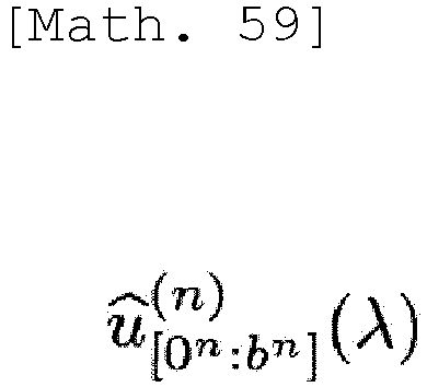
- In a case where
Algorithm 4 is used in a decoder of a polar information source code, accessing the code word u_I1 and the auxiliary information vector {y_bn}_bn∈[0n:1n],


[Math. 62]
[Math. 63]
- That is, l in Formula (30) is the most probable path (sequence).
- In a case where s=parity(xn) is added to the code word u_I1 by using an external parity check function parity,
with respect to l satisfying
- In a case where
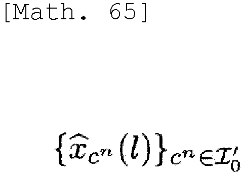
Algorithm 4 is used in a decoder of a systematic polar communication channel code, accessing the communication channel output vector {y_bn}_bn∈[0n:1n] and the shared vector u_I1, reproduction defined by Formulas (29) and (30)
- In a case where the code word (for example, polar code with CRC [9]) having a check vector s satisfying s=parity(xn) for all the communication channel inputs xn is used using the external parity check function parity,
with respect to l satisfying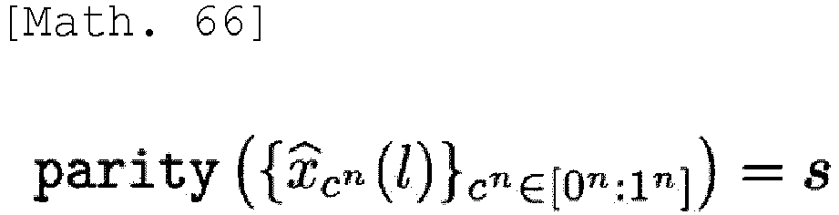

- In a case where
Algorithm 4 is used for a decoder of a non-systematic polar communication channel code, the binary variable

lines Algorithm 6,lines

[Math. 70]

Algorithm 6 is shown inFig. 21 , and the modifiedalgorithm 7 is shown inFig. 22 . - In a case where the code word (for example, polar code with CRC [9]) having a check vector s satisfying s=parity(xn) for all the communication channel inputs xn is used using the external parity check function parity, with respect to l in which the corresponding communication channel input, which is defined by Formula (29),


- Remark 2:
Line 17 ofAlgorithm 4 is unnecessary in a case where a real variable with infinite precision is used. In the above description, it is assumed to use a real variable with finite precision (floating point) in order to avoid P[λ] becoming 0 due to truncation when bn increases. Regardless of whether P[λ] is infinite precision or not, while (bn=0n) and bn∈I1 are continuously satisfied from the beginning,line 17 ofAlgorithm 4 andline 2 ofAlgorithm 5 can be skipped. - Note that this type of technique is used in [9,
Algorithm 10,lines 20 to 25], and this technique has been repeated Nn times. In contrast to that,Algorithm 4 in the present embodiment uses this technique outside the update of the parameter {Θ[λ]}L-1 λ=0 (Algorithm 2), and magnifyP(λ) is repeated N times. - Remark 3: Assuming that L is a power of 2, A=L is always satisfied in
line 13 ofAlgorithm 4. Therefore, since Λ+l≥L is always satisfied,line 14 ofAlgorithm 4 andlines 9 to 12 ofAlgorithm 7 can be omitted.Fig. 23 illustratesAlgorithm 4 after skip processing ofRemark 2 and omission ofRemark 3 with respect toAlgorithm 4. In addition,Algorithm 7 after omission ofRemark 3 with respect toAlgorithm 7 is illustrated inFig. 24 . Note thatline 9 ofAlgorithm 4 inFig. 23 corresponds to skip processing ofRemark 2 with respect toAlgorithm 5 inFig. 9 , skip is not performed in extendPath that callsline 18 ofAlgorithm 4 inFig. 23 , and the processing ofAlgorithm 5 inFig. 9 is executed as it is. Further,Fig. 25 illustrates a modification whenAlgorithm 7 illustrated inFig. 24 is applied to the non-systematic communication channel code. - Remark 4: Since
Algorithm 6 andAlgorithm 7 have thesame lines 2 to 3,lines 2 to 3 ofAlgorithm 6 can be omitted, and then lines 1 to 4 ofAlgorithm 7 can be moved between theline 8 and theline 9 ofAlgorithm 4. - The description so far has used a binary representation of the index. Implementation of this representation will now be described.
- In an implementation, the binary representation bk∈[0k:1k] may be represented by a corresponding integer in {0,...,2k-1}. It is assumed that i(bk) is the corresponding integer of bk.
- For a given bk∈[0k:1k], bk-1 is the least significant bit of bk, and the corresponding integer can be obtained as i(bk-1)=i(bk)mod2. This is used in
lines Algorithm 1 andlines - In
line 9 of Algorithm 1 (Fig. 5 ),line 2 of Algorithm 2 (Fig. 6 ), andline 5 of Algorithm 3 (Fig. 7 ), bk-1 is used for a given bk. bk-1 can be obtained by using a 1-bit right shift of bk. Alternatively, a corresponding integer can be obtained by using a relational expression of i(bk-1)=floor(i(bk)/2) . Here, floor is a function that outputs an integer value obtained by rounding down decimal places with respect to an input of a real number. - In
lines Algorithm 2 andlines Algorithm 3,c n-k0 can be obtained by setting the least significant bit ofc n-k0 to 1 and using cn-k and a 1-bit left shift ofc n-k1. Alternatively, the corresponding integer can be obtained using the following relational expression.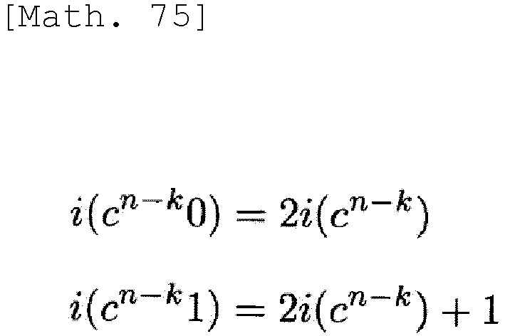
- In
lines Algorithm 1,line 3 ofAlgorithm 5,lines Algorithm 6, andlines Algorithm 7, the corresponding integer of the null character string c° can be defined as i(c0)=0. When k=n, this also appears inlines Algorithm 2 andlines Algorithm 3. Here, the null character string is distinguished from thebinary symbol 0 according to the value k. Inlines Algorithm 3, the null character string b-1 appears when k=1. i(b-1)=0 can be defined and can be distinguished from thebinary symbol 0 according to the value k. The following relational expression is obtained.
- As described in
Remark 1, in a case whereAlgorithm 1 is applied to the binary erasure channel, Θ[k][cn-k]∈{-1,0,1} is obtained. Given this, two refinements toAlgorithm 2 can be introduced. - First,
Fig. 14 illustratesAlgorithm 2. In thisAlgorithm 2, it is assumed that Θ[k][cn-k] is represented by a 3-bit signed integer including a sign bit and two bits representing an absolute value. -
Fig. 15 illustratesAlgorithm 2. In thisAlgorithm 2, - It is assumed that

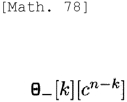
line 7 ofAlgorithm 1 can be replaced with


- In this
Algorithm 2, ∧ represents an AND computation, ∨ represents an OR computation, and

- Here, the content of the algorithm in
line 5 ofAlgorithm 7 shown inFig. 11 will be described. In the present embodiment,line 5 ofAlgorithm 7 can be implemented by Algorithm 7-1 (markPath(X)) illustrated inFig. 16 . The algorithm of selectPath(0,2·λ-1) inline 5 in Algorithm 7-1 is shown inFig. 17 as Algorithm 7-2. The algorithm of partition(left,right) online 2 in Algorithm 7-2 is shown inFig. 18 as Algorithm 7-3. The algorithm of swapIndex in Algorithm 7-3 is shown inFig. 19 as Algorithm 7-4. - Algorithms 7-1 to 7-4 can access the memory spaces {P[λ]}2L-1 λ=0, { Index[λ]}2L-1 λ=1, and {Active [λ]}2L-1 λ=0. Here, Index[λ]∈{0,...2L-1} is an integer variable. The calculation result is stored in {Active[λ]}2Λ-1 λ=0.
- Remark 5: As mentioned in [9], instead of adopting selectPath(0,2·λ-1) in
line 5 of Algorithm 7-1, {Index[λ]}λ-1 λ=0 may be simply sorted to obtain P[Index[0]]≥P[Index[1]]≥···≥P[Index[Λ-1]]. The time complexity of sorting is O(ΛlogΛ), but in a case where Λ is small, the time complexity may be faster than selectPath(0,2·Λ-1). - Remark 6: Line 1 (can be omitted) of Algorithm 7-3 guarantees that the average time complexity of selectPath(0,2·Λ-1) is O(Λ). By selecting the index corresponding to the median of {P[λ]}right λ=left, this line can be replaced, and the worst-case time complexity O(A) can be guaranteed (refer to [4]).
- Hereinafter, as a summary of each algorithm, input, output, and the like for each algorithm will be described. Note that the number n of times of polar conversion is a constant, and can be referred to from all the algorithms. The block length is N=2n.
- For example, the input information described below is input from the
input unit 210 in thedecoding device 200 shown inFig. 3 , stored in thedata storage unit 240, and referred to by thecomputation unit 220 that executes the algorithm. Reference to information by thecomputation unit 220 that executes the algorithm may be expressed as input of information to the algorithm. A computation result by thecomputation unit 220 is output to and stored in thedata storage unit 240. The computation result (original message) is read from thedata storage unit 240 by thecomputation unit 220 and output from theoutput unit 230. - The input to
Algorithm 1 is as follows. -
- ·Position information I1 of frozen bit This is a subset of {0n,...,1n}.
- ·Information u_I1 of frozen bit in the case of the information source code, the information source code is transmitted as a code word from the
encoding device 100 to thedecoding device 200. - The code word in the case of the information source code is more specifically as follows.
- The
encoding device 100 defines u(0)_bn=x_bn for the information source output x_[0n:1n], and applies a known polar conversion algorithm
to obtain {u[lsb(n)][bn]}_bn∈[0n:1n]. At this time, {u[lsb(n)][bn]}_bn∈I1 is a code word. - ·Series of probability distributions

- This is set as follows by the
computation unit 220 depending on the object to be applied. -
- In the case of the information source code, the information observed by the
encoding device 100 is set as (X1,...,Xn), and the auxiliary information observed by thedecoding device 200 is set as (Y1,...,Yn). While conditional probability distribution of X_bn after observation of Y_bn is


- In the case of the communication channel code, the communication channel input is (X1,...,Xn), and the communication channel output observed by the
decoding device 200 is (Y1,...,Yn). The conditional probability distribution of the communication channel is


- The communication channel input for the systematic communication channel code is more specifically as follows.
- The
encoding device 100 sets x_I0' as a message vector and u(0)_I1 as information shared by theencoding device 100 and the decoding device 200 (for example, all are set to 0). Then, a known polar code algorithm is applied to obtain (x_I1',u_I0) from (x_I0',u_I1). Here, the relationship of I0, I1, I0', and I1' is defined by the above-described Formulas (1) and (2). At this point, the communication channel input (also referred to as a code word) that is the output ofencoding device 100 is obtained by aligning (x_I0',x_I1') in the order of indices. - The communication channel input for the non-systematic communication channel code is more specifically as follows.
- The
encoding device 100 sets u(0)_I0 as a message vector and u(0)_I1 as information shared by theencoding device 100 and the decoding device 200 (for example, all are set to 0). By applying a known polar code algorithm to this,
encoding device 100. - As described above, the output from
Algorithm 1 is stored in the memory space shown in [Math. 30]. - The reproduction information as the decoding result is obtained by the following interpretation depending on the object to be applied.
-
- In the case of the information source code, the
computation unit 220 sets ^x_[0n:1n] defined in the above-described Formula (25) as the reproduced information source sequence with reference to the memory space of U shown in [Math. 30]. - In the case of the systematic communication channel code, the
computation unit 220 refers to the memory space of U shown in [Math. 30], and sets ^x_I0' defined in the above-described Formula (25) as a reproduced message. Here, I0' is as described above. - In the case of the non-systematic communication channel code, as described above, the modified
algorithm 1 shown inFig. 20 is used. That is, the memory area {M[bn]:bn∈I0} corresponding to the position is prepared in the non-frozen bit, and the result is stored. The reproduction message becomes ^u_I0 defined by ^u_bn=M[bn]. - The input to
Algorithm 2 is as follows. -
- ·Reference is made to the memories Θ and U used in
Algorithm 1. - ·Integer k.
- ·Binary representation bn of index. As described previously, implementations may also handle bn as an integer.
-
- ·In a case where the condition is satisfied,
Algorithm 2 is recursively called, and the content of Θ is rewritten. -
- ·Reference is made to the memory U used in
Algorithm 1. - ·Integer k.
- ·Binary representation bn of index Implementations may also treat bn as an integer.
-
- ·After the content of U is rewritten, when the condition is satisfied,
Algorithm 3 is recursively called. -
- ·The same information as the input information to
Algorithm 1 - ·List size L.
- The output from
Algorithm 4 is stored in the memory spaces (memory areas) of Θ, U, and P as described above. Specifically, this is as follows.
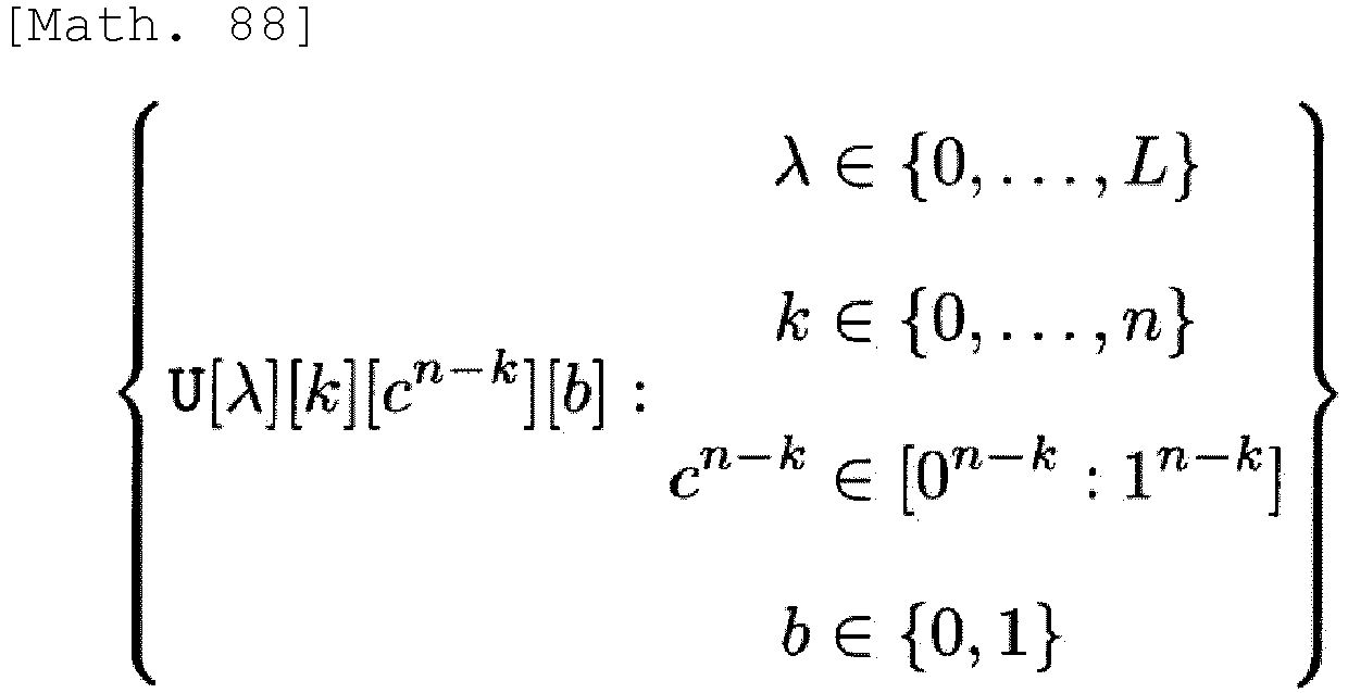

- The reproduction information as the decoding result is obtained by the following interpretation depending on the object to be applied.
-
- In the case of the information source code, the
computation unit 220 obtains 1 by the above-described Formula (30) with reference to the above P, and with reference to the above U,

- In the case of the systematic communication channel code, the
computation unit 220 obtains 1 by the above-described Formula (30) with reference to the P, and with reference to the above U, ^x_I'0 defined by Formula (25) is set as a reproduced message. Here, I'0 is as described above. - In a case where
Algorithms 4 to 7 are applied to a non-systematic communication channel code, as described above, the memory area shown in [Math. 68] is prepared and the result is stored. The modifiedalgorithms Figs. 21 ,22 , and25 , respectively. The reproduction message is as shown in [Math. 70] and [Math. 71]. -
- ·Reference is made to the above memories Θ, U, and P.
- ·The information u_I1 of the frozen bit described in the input of Algorithm 4 (Algorithm 1) is referred to.
- ·Binary representation bn of index Implementations may also treat bn as an integer.
- ·Size A of valid (active) list
-
- ·The content of the above memories U and P is rewritten.
-
- ·Reference is made to the above memories Θ, U, and P.
- ·Binary representation bn of index Implementations may also treat bn as an integer.
- ·Size Λ of valid (active) list
-
- ·The content of the above memories U and P is rewritten.
- Here, the memory
{Active[λ]:x∈{0,...,2L-1]} is used. -
- ·Reference is made to the above memories Θ, U, P, and Active.
- ·Binary representation bn of index Implementations may also treat bn as an integer.
- ·Size A of valid (active) list
-
- ·The content of the above memories U, P, and Active is rewritten. In
Algorithm 7 illustrated inFig. 25 , the content of M is further rewritten. -
Algorithm 8 is an algorithm corresponding to copyPath(λ',λ) inline 4 of Algorithm 6 (Fig. 10 ) andlines Fig. 11 ), and implements a function of copying the state of the Xth list to a memory that stores the state of the λ'th list. -
- ·Reference is made to the above memories Θ and U.
- ·Index λ' of list of copy destinations.
- ·Index λ' of list of copy sources.
-
- ·The content of the above memories Θ and U is rewritten.
- The
algorithm 9 is an algorithm that implements rewriting of content of the above memory P (setting the maximum value to 1 without change of ratio of real number stored in memory). -
- ·Reference is made to the above memory P.
- ·Size Λ of valid (active) list.
-
- ·The content of the above memory P is rewritten.
-
Algorithm 2 illustrated inFigs. 14 and15 is an algorithm that speeds upAlgorithm 2 whenAlgorithm 1 is applied to a polar code for an erasure channel. The input/output is the same as that ofAlgorithm 2. - Algorithms 7-1 to 7-4 are algorithms that set Active[λ]=1 only to the top L values of P[λ] as described in
line 5 of Algorithm 7 (Fig. 11 ). - As described above, in order to simplify the configuration,
Algorithm 4 andAlgorithm 7 in a case where it is assumed that the set I0 is not an empty set, L is a power of 2, and only a real number computation with finite accuracy is possible (although not realistic, in the case of infinite accuracy,line 27 ofalgorithm 4 inFig. 23 can be deleted) are as shown inFigs. 23 to 25 . Note that, in a case where I0 is an empty set, L=1 is set, and the processing up tolines 5 to 8 ofAlgorithm 4 illustrated inFig. 23 is skipped and the processing up toline 14 is finished. - As described in
Remark 1, in the case of thedecoding device 200 for the erasure channel, it can be assumed that the value Θ[k][cn-k] takes any value of {-1,0,1}. - When
line 7 of Algorithm 1 (Fig. 5 ) is replaced with

lines 4 to 8 of Algorithm 1 (Fig. 5 ) may be any processing as long as the values in the tables illustrated inFigs. 26 to 28 are substituted into Θ[k][cn-k]. Two examples (Example A, Example B) will be described below. - In a case of being applied to
Algorithms 4 to 9, Θ[λ][k][cn-k] can be a variable having a value of {-1,0,1}, and P[λ] can be an N-bit unsigned integer variable. In this case, the processing of magnifyP inline 17 ofAlgorithm 4 is unnecessary. Further,
Since
line 2 ofAlgorithm 5,lines 2 to 3 ofAlgorithm 6, andlines 2 to 3 ofAlgorithm 7,
in a case of
- The division can be omitted by using
Algorithm 2 illustrated inFig. 14 instead ofAlgorithm 2 inFig. 6 . Since carrying-up occurs, three bits including a sign are required for Θ[k][cn-k]. - Note that, when this method is applied to successive cancellation list decoding (Algorithm 4), a change may be made only by regarding a real variable as an integer variable.
- Further, Θ[k][cn-k] is represented as illustrated in
Fig. 29 .
- In this case, the tables illustrated in
Figs. 30 to 32 may be implemented inlines 4 to 8 ofAlgorithm 2. - This can be implemented by replacing
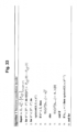
line 7 of Algorithm 1 (Fig. 5 ) withline 7 illustrated inFig. 33 , and usingAlgorithm 2 illustrated inFig. 15 instead ofAlgorithm 2 inFig. 6 .Line 7 ofAlgorithm 1 may be

- Note that, when this method is applied to successive cancellation list decoding (Algorithm 4),

- In a case where the technique according to the present embodiment (referred to as a proposed method) is compared with the technique of Reference Literature [9] (referred to as a conventional method), two values Pλ[β][0] and Pλ[β][1] indicated by P of the conventional method are expressed by one value Θ[k][cn-k] by applying the symmetric parameterization in the proposed method [Algorithm 2], and thus, in the proposed method, the used memory amount is half that in the conventional method. As a result, the calculation amount can also be reduced. In particular, in list decoding, it is possible to greatly reduce a processing time in a case where states of candidates are copied.
- In addition, a stack memory is used in the processing of the conventional method, but a memory space having a fixed address is directly operated in the proposed method. Thus, the operation in the conventional method regarding the stack memory is simplified in the proposed method.
- Furthermore, with the technique according to the present embodiment, it is possible to uniformly perform decoding for the communication channel code and decoding for the information source code.
- In the present specification, at least a decoding device, a decoding method, and a program described in clauses described below are described.
- A decoding device, including:
- an input unit that inputs a code word encoded by a polar code from an original message;
- a computation unit that decodes the original message from the code word based on a conditional probability expressed by a symmetric parameterization and having observation information as a condition; and
- an output unit that outputs the decoded original message.
- The decoding device according to
clause 1, in which - in a case where the decoding device is applied to decoding for an information source code,
- the input unit inputs information of a frozen bit as the code word from a noise-free communication channel or a storage medium, and
- the computation unit decodes the original message by using auxiliary information as the observation information.
- The decoding device according to
clause 1, in which - in a case where the decoding device is applied to decoding for a communication channel code,
- the input unit inputs, as the code word, a communication channel output from a communication channel having noise, and
- the computation unit decodes the original message by using the communication channel output as the observation information.
- The decoding device according to
clause 3, in which - in a case where the decoding device is applied to decoding for a systematic communication channel code,
- information of a frozen bit is shared between an encoding side and a decoding side,
- the input unit inputs the communication channel output in which the original message obtained by polar conversion on the encoding side and an additional information are used as communication channel inputs, and
- the computation unit decodes the original message by using the information of the frozen bit and the communication channel output.
- The decoding device according to
clause 3, in which - in a case where the decoding device is applied to decoding for a non-systematic communication channel code,
- information of a frozen bit is shared between an encoding side and a decoding side,
- the input unit inputs the communication channel output in which information of non-frozen bit and information obtained by polar conversion from the information of the frozen bit on the encoding side are used as communication channel inputs, and
- the computation unit decodes the original message by storing a determination result of 0 or 1 in a memory area corresponding to a position of a non-frozen bit based on the information of the frozen bit and the communication channel output.
- The decoding device according to any one of
clauses 1 to 5, in which
the computation unit executes list decoding for selecting a sequence of a most probable path from among the number (predetermined list size) of survival paths. - A decoding method executed by a decoding device, including:
- an input step of inputting a code word encoded by a polar code from an original message;
- a computation step of decoding the original message from the code word based on a conditional probability expressed by a symmetric parameterization and having observation information as a condition; and
- an output step of outputting the decoded original message.
- A program for causing a computer to function as each unit in the decoding device according to any one of
clauses 1 to 6. - Although the present embodiment has been described above, the present invention is not limited to such a specific embodiment, and various modifications and changes can be made within the scope of the gist of the present invention described in the claims.
-
- [1] E. Arikan, "Channel polarization:a method for constructing capacity-achieving codes for symmetric binary-input memoryless channels", IEEE Trans. Inform. Theory, vol. IT-55, no. 7, pp. 3051-3073, Jul. 2009.
- [2] E. Arikan, "Source polarization", Proc. 2010 IEEE Int. Symp. Inform. Theory, Austin, U.S.A., June 13-18, 2010, pp. 899-903. (corresponding to Non-Patent Literature 2)
- [3] E. Arikan, "Systematic polar coding", IEEE Communications Letters, vol. 15, no. 8, pp. 860-862, Aug. 2010.
- [4] M. Blum, R. W. Floyd, V. Pratt, R. L. Rivest, and R. E. Tarjan, "Time bounds for selection", J. Computer and System Sciences, vol. 7, no. 4, pp. 448-461, 1973.
- [5] R. Mori and T. Tanaka, "Source and channel polarization over finite fields and Reed-Solomon matrices", IEEE Trans. Inform. Theory, vol. IT-60, no. 5, pp. 2720-2736, May 2014.
- [6] J. Muramatsu, "Successive-cancellation decoding of linear source code", Proceedings of the 2019 IEEE Information Theory Workshop, Visby, Sweden, Aug. 25-28, 2019. Extended version available at arXiv:1903.11787[cs.IT], 2019.
- [7] E. S, as,oglu, "Polarization and polar codes", Fund. Trends Commun. Inf. Theory, vol. 8, no. 4, pp. 259-381, Oct. 2012.
- [8] I. Tal and A. Vardy, "How to construct polar codes", IEEE Trans. Inform. Theory, vol. IT-59, no. 10, pp. 6563-6582, Oct. 2013.
- [9] I. Tal and A. Vardy, "List decoding of polar codes", IEEE Trans. Inform. Theory, vol. IT-61, no. 5, pp. 2213-2226, May. 2015. (corresponding to Non-Patent Literature 1)
-
- 100
- Encoding device
- 200
- Decoding device
- 210
- Input unit
- 220
- Computation unit
- 230
- Output unit
- 240
- Data storage unit
- 1000
- Drive device
- 1001
- Recording medium
- 1002
- Auxiliary storage device
- 1003
- Memory device
- 1004
- CPU
- 1005
- Interface device
- 1006
- Display device
- 1007
- Input device
- 1008
- Output device
Claims (8)
- A decoding device, comprising:an input unit that inputs a code word encoded by a polar code from an original message;a computation unit that decodes the original message from the code word based on a conditional probability expressed by a symmetric parameterization and having observation information as a condition; andan output unit that outputs the decoded original message.
- The decoding device according to claim 1, wherein,in a case where the decoding device is applied to decoding for an information source code,the input unit inputs information of a frozen bit as the code word from a noise-free communication channel or a storage medium, andthe computation unit decodes the original message by using auxiliary information as the observation information.
- The decoding device according to claim 1, wherein,in a case where the decoding device is applied to decoding for communication channel code,the input unit inputs, as the code word, a communication channel output from a communication channel having noise, andthe computation unit decodes the original message by using the communication channel output as the observation information.
- The decoding device according to claim 3, wherein,in a case where the decoding device is applied to decoding for a systematic communication channel code,information of a frozen bit is shared between an encoding side and a decoding side,the input unit inputs the communication channel output in which the original message obtained by polar conversion on the encoding side and an additional information are used as communication channel inputs, andthe computation unit decodes the original message by using the information of the frozen bit and the communication channel output.
- The decoding device according to claim 3, wherein,in a case where the decoding device is applied to decoding for a non-systematic communication channel code,information of a frozen bit is shared between an encoding side and a decoding side,the input unit inputs the communication channel output in which information of non-frozen bit and information obtained by polar conversion from the information of the frozen bit on the encoding side are used as communication channel inputs, andthe computation unit decodes the original message by storing a determination result of 0 or 1 in a memory area corresponding to a position of a non-frozen bit based on the information of the frozen bit and the communication channel output.
- The decoding device according to any one of claims 1 to 5, wherein
the computation unit executes list decoding for selecting a sequence of a most probable path from among the number (predetermined list size) of survival paths. - A decoding method executed by a decoding device, comprising:an input step of inputting a code word encoded by a polar code from an original message;a computation step of decoding the original message from the code word based on a conditional probability expressed by a symmetric parameterization and having observation information as a condition; andan output step of outputting the decoded original message.
- A program for causing a computer to function as each unit in the decoding device according to any one of claims 1 to 6.
Applications Claiming Priority (1)
| Application Number | Priority Date | Filing Date | Title |
|---|---|---|---|
| PCT/JP2021/000035 WO2022145057A1 (en) | 2021-01-04 | 2021-01-04 | Decoding device, decoding method, and program |
Publications (2)
| Publication Number | Publication Date |
|---|---|
| EP4274102A1 true EP4274102A1 (en) | 2023-11-08 |
| EP4274102A4 EP4274102A4 (en) | 2024-09-04 |
Family
ID=82259194
Family Applications (1)
| Application Number | Title | Priority Date | Filing Date |
|---|---|---|---|
| EP21914919.2A Pending EP4274102A4 (en) | 2021-01-04 | 2021-01-04 | DECODING DEVICE, DECODING METHOD AND PROGRAM |
Country Status (5)
| Country | Link |
|---|---|
| US (1) | US12301259B2 (en) |
| EP (1) | EP4274102A4 (en) |
| JP (1) | JP7540511B2 (en) |
| CN (1) | CN116711219A (en) |
| WO (1) | WO2022145057A1 (en) |
Family Cites Families (13)
| Publication number | Priority date | Publication date | Assignee | Title |
|---|---|---|---|---|
| WO2015180187A1 (en) * | 2014-05-30 | 2015-12-03 | 华为技术有限公司 | Method and apparatus for constructing punctured polar code |
| US10581462B2 (en) * | 2015-12-01 | 2020-03-03 | Huawei Technologies Co., Ltd. | Signature-enabled polar encoder and decoder |
| WO2017156792A1 (en) * | 2016-03-18 | 2017-09-21 | Qualcomm Incorporated | Transmission of new data in a hybrid automatic repeat request (harq) retransmission with polar coded transmissions |
| WO2018058294A1 (en) * | 2016-09-27 | 2018-04-05 | Qualcomm Incorporated | Harq techniques for polar codes |
| CA3050076C (en) * | 2017-02-06 | 2022-08-30 | Telefonaktiebolaget Lm Ericsson (Publ) | Concatenated polar code with adaptive error detection |
| CN114553243A (en) * | 2017-03-02 | 2022-05-27 | 华为技术有限公司 | Polar code coding and decoding method and device |
| EP3376672B1 (en) * | 2017-03-13 | 2019-09-18 | Mitsubishi Electric R & D Centre Europe B.V. | Method for dynamically configuring a divide and conquer structure of a polar-code based encoder |
| EP3602794B1 (en) * | 2017-03-30 | 2021-11-17 | Nec Corporation | Check bit concatenated polar codes |
| CN108809485B (en) * | 2017-05-02 | 2020-02-21 | 华为技术有限公司 | A method and apparatus for encoding |
| US10348336B2 (en) | 2017-06-06 | 2019-07-09 | Tsofun Algorithm Ltd. | System and method for early termination of decoding in a multi user equipment environment |
| US11777533B2 (en) * | 2018-11-27 | 2023-10-03 | Telefonaktiebolagget LM Ericsson (Publ) | Method for polar decoding with dynamic successive cancellation list size and polar decoder |
| US11405055B2 (en) * | 2019-06-26 | 2022-08-02 | Polaran Haberlesme Teknolojileri Anonim Sirketi | Methods and apparatus for error correction coding with triangular factorization of generator matrix |
| US11063614B1 (en) * | 2019-11-21 | 2021-07-13 | Cadence Design Systems, Inc. | Polar decoder processor |
-
2021
- 2021-01-04 US US18/258,967 patent/US12301259B2/en active Active
- 2021-01-04 EP EP21914919.2A patent/EP4274102A4/en active Pending
- 2021-01-04 JP JP2022572882A patent/JP7540511B2/en active Active
- 2021-01-04 CN CN202180088092.1A patent/CN116711219A/en active Pending
- 2021-01-04 WO PCT/JP2021/000035 patent/WO2022145057A1/en not_active Ceased
Also Published As
| Publication number | Publication date |
|---|---|
| JPWO2022145057A1 (en) | 2022-07-07 |
| JP7540511B2 (en) | 2024-08-27 |
| CN116711219A (en) | 2023-09-05 |
| WO2022145057A1 (en) | 2022-07-07 |
| EP4274102A4 (en) | 2024-09-04 |
| US20240056102A1 (en) | 2024-02-15 |
| US12301259B2 (en) | 2025-05-13 |
Similar Documents
| Publication | Publication Date | Title |
|---|---|---|
| EP3602423B1 (en) | Magic state distillation with low space overhead and asymptotic input count | |
| Shamir et al. | Low-complexity sequential lossless coding for piecewise-stationary memoryless sources | |
| Carrier et al. | Reduction from sparse LPN to LPN, dual attack 3.0 | |
| EP1995974B1 (en) | Method for realizing arithmetic coding | |
| Shibayama et al. | Permutation-invariant quantum codes for deletion errors | |
| Li | An automated theorem proving framework for information-theoretic results | |
| KR20230040702A (en) | Method and apparatus for generating a decoding position control signal for decoding using polar codes | |
| Renes | Duality of channels and codes | |
| Hashimoto et al. | Central limit theorems for large graphs: Method of quantum decomposition | |
| Moskovskaya et al. | Design of BCH polarization kernels with reduced processing complexity | |
| Zunker et al. | Enumeration of minimum weight codewords of pre-transformed polar codes by tree intersection | |
| Han et al. | The edit-distance between a regular language and a context-free language | |
| Arpin et al. | Error floor prediction with Markov models for QC-MDPC codes | |
| Li et al. | On the Complexity of Hybrid $ n $-Term Karatsuba Multiplier for Trinomials | |
| Cavicchioni et al. | Information set decoding for ring-linear codes | |
| Myasnikov et al. | Parallel complexity for nilpotent groups | |
| US12301259B2 (en) | Decoding apparatus, decoding method and program | |
| KR20220141044A (en) | Apparatus and method for successive cancellation flip decoding of polar code | |
| JP2010535459A (en) | Coordinate ascent method for linear programming decoding. | |
| Cengellenmis et al. | Reversible DNA codes from skew cyclic codes over a ring of order 256 | |
| Chee et al. | Efficient encoding/decoding of irreducible words for codes correcting tandem duplications | |
| Daykin et al. | String comparison and Lyndon-like factorization using V-order in linear time | |
| Shuval et al. | List decoding of universal polar codes | |
| Tran | Improved Quantum Algorithms for Solving Abelian Hidden Subgroup Problems for Subgroups of Arbitrary Index | |
| HK40091704A (en) | Decoding device, decoding method, and program |
Legal Events
| Date | Code | Title | Description |
|---|---|---|---|
| STAA | Information on the status of an ep patent application or granted ep patent |
Free format text: STATUS: THE INTERNATIONAL PUBLICATION HAS BEEN MADE |
|
| PUAI | Public reference made under article 153(3) epc to a published international application that has entered the european phase |
Free format text: ORIGINAL CODE: 0009012 |
|
| STAA | Information on the status of an ep patent application or granted ep patent |
Free format text: STATUS: REQUEST FOR EXAMINATION WAS MADE |
|
| 17P | Request for examination filed |
Effective date: 20230628 |
|
| AK | Designated contracting states |
Kind code of ref document: A1 Designated state(s): AL AT BE BG CH CY CZ DE DK EE ES FI FR GB GR HR HU IE IS IT LI LT LU LV MC MK MT NL NO PL PT RO RS SE SI SK SM TR |
|
| DAV | Request for validation of the european patent (deleted) | ||
| DAX | Request for extension of the european patent (deleted) | ||
| A4 | Supplementary search report drawn up and despatched |
Effective date: 20240807 |
|
| RIC1 | Information provided on ipc code assigned before grant |
Ipc: H03M 13/00 20060101ALI20240801BHEP Ipc: H03M 13/13 20060101AFI20240801BHEP |
|
| RAP3 | Party data changed (applicant data changed or rights of an application transferred) |
Owner name: NTT, INC. |