EP4274056A1 - Network system, and method for controlling network system - Google Patents
Network system, and method for controlling network system Download PDFInfo
- Publication number
- EP4274056A1 EP4274056A1 EP21915196.6A EP21915196A EP4274056A1 EP 4274056 A1 EP4274056 A1 EP 4274056A1 EP 21915196 A EP21915196 A EP 21915196A EP 4274056 A1 EP4274056 A1 EP 4274056A1
- Authority
- EP
- European Patent Office
- Prior art keywords
- power
- direct
- current
- grids
- current grids
- Prior art date
- Legal status (The legal status is an assumption and is not a legal conclusion. Google has not performed a legal analysis and makes no representation as to the accuracy of the status listed.)
- Pending
Links
Images



Classifications
-
- H—ELECTRICITY
- H02—GENERATION; CONVERSION OR DISTRIBUTION OF ELECTRIC POWER
- H02J—ELECTRIC POWER NETWORKS; CIRCUIT ARRANGEMENTS OR SYSTEMS FOR SUPPLYING OR DISTRIBUTING ELECTRIC POWER; SYSTEMS FOR STORING ELECTRIC ENERGY
- H02J13/00—Circuit arrangements for providing remote monitoring or remote control of equipment in a power distribution network
- H02J13/13—Circuit arrangements for providing remote monitoring or remote control of equipment in a power distribution network characterised by the transmission of data to equipment in the power network
- H02J13/1331—Circuit arrangements for providing remote monitoring or remote control of equipment in a power distribution network characterised by the transmission of data to equipment in the power network using wireless data transmission
-
- H—ELECTRICITY
- H01—ELECTRIC ELEMENTS
- H01Q—ANTENNAS, i.e. RADIO AERIALS
- H01Q21/00—Antenna arrays or systems
-
- H—ELECTRICITY
- H02—GENERATION; CONVERSION OR DISTRIBUTION OF ELECTRIC POWER
- H02J—ELECTRIC POWER NETWORKS; CIRCUIT ARRANGEMENTS OR SYSTEMS FOR SUPPLYING OR DISTRIBUTING ELECTRIC POWER; SYSTEMS FOR STORING ELECTRIC ENERGY
- H02J1/00—Circuit arrangements for DC mains or DC distribution networks
-
- H—ELECTRICITY
- H04—ELECTRIC COMMUNICATION TECHNIQUE
- H04Q—SELECTING
- H04Q9/00—Arrangements in telecontrol or telemetry systems for selectively calling a substation from a main station, in which substation desired apparatus is selected for applying a control signal thereto or for obtaining measured values therefrom
-
- H—ELECTRICITY
- H02—GENERATION; CONVERSION OR DISTRIBUTION OF ELECTRIC POWER
- H02J—ELECTRIC POWER NETWORKS; CIRCUIT ARRANGEMENTS OR SYSTEMS FOR SUPPLYING OR DISTRIBUTING ELECTRIC POWER; SYSTEMS FOR STORING ELECTRIC ENERGY
- H02J2103/00—Details of circuit arrangements for mains or AC distribution networks
- H02J2103/30—Simulating, planning, modelling, reliability check or computer assisted design [CAD] of electric power networks
- H02J2103/35—Grid-level management of power transmission or distribution systems, e.g. load flow analysis or active network management
-
- H—ELECTRICITY
- H02—GENERATION; CONVERSION OR DISTRIBUTION OF ELECTRIC POWER
- H02J—ELECTRIC POWER NETWORKS; CIRCUIT ARRANGEMENTS OR SYSTEMS FOR SUPPLYING OR DISTRIBUTING ELECTRIC POWER; SYSTEMS FOR STORING ELECTRIC ENERGY
- H02J2105/00—Networks for supplying or distributing electric power characterised by their spatial reach or by the load
- H02J2105/10—Local stationary networks having a local or delimited stationary reach
-
- H—ELECTRICITY
- H04—ELECTRIC COMMUNICATION TECHNIQUE
- H04Q—SELECTING
- H04Q2209/00—Arrangements in telecontrol or telemetry systems
- H04Q2209/20—Arrangements in telecontrol or telemetry systems using a distributed architecture
- H04Q2209/25—Arrangements in telecontrol or telemetry systems using a distributed architecture using a mesh network, e.g. a public urban network such as public lighting, bus stops or traffic lights
-
- H—ELECTRICITY
- H04—ELECTRIC COMMUNICATION TECHNIQUE
- H04Q—SELECTING
- H04Q2209/00—Arrangements in telecontrol or telemetry systems
- H04Q2209/40—Arrangements in telecontrol or telemetry systems using a wireless architecture
- H04Q2209/43—Arrangements in telecontrol or telemetry systems using a wireless architecture using wireless personal area networks [WPAN], e.g. 802.15, 802.15.1, 802.15.4, Bluetooth® or Zigbee®
-
- H—ELECTRICITY
- H04—ELECTRIC COMMUNICATION TECHNIQUE
- H04Q—SELECTING
- H04Q2209/00—Arrangements in telecontrol or telemetry systems
- H04Q2209/60—Arrangements in telecontrol or telemetry systems for transmitting utility meters data, i.e. transmission of data from the reader of the utility meter
Definitions
- the present invention relates to a network system and a control method of a network system.
- a world smart city market cumulatively reaches a scale of 3100 trillion yen in 20 years from 2010 to 2030, and, in energy-related markets that play a central role, it is expected to achieve a market scale of about 720 trillion yen in relation to smart grids, a market scale of about 310 trillion yen in relation to a next-generation vehicle, such as an electric vehicle, and a market scale of about 380 trillion yen in relation to renewable energy. Therefore, smart city development plans are promoted in a large number of countries and regions, and some of the plans are already put into practice.
- Patent Literature 1 proposes a system that connects distributed energy resources including solar power, wind-power generation, storage batteries, and power storage systems, social infrastructures including EVs and charging stations, a home energy management system (HEMS), a building energy management system (BEMS), and power plants to one another by communication grids and power grids.
- distributed energy resources including solar power, wind-power generation, storage batteries, and power storage systems
- social infrastructures including EVs and charging stations
- BEMS building energy management system
- power plants to one another by communication grids and power grids.
- a power network system disclosed in Patent Literature 1 for flexibly interchanging power among a plurality of power cells, for example.
- the power cells disclosed in Patent Literature 1 include loads, such as houses and buildings, power generation facilities, such as solar panels and wind generators, power storage facilities, such as storage batteries, and power routers.
- the power routers are connected to a bulk power system that transmits power from power routers of different power cells or power plants.
- the power router of each of the cells is connected to a management server via a communication network, and power is flexibly interchanged among the power cells under the control of the management server.
- the power routers are integrally controlled, so that if a failure occurs between the power routers and the management server due to a disaster or the like, it becomes impossible to flexibly interchange power among the power cells.
- autonomous distributed control it becomes possible to cope with the failure; however, it is difficult to optimize the entire system and interchange the power by only the autonomous distributed control, and therefore, a technology for increasing resilience is needed.
- the present invention has been conceived in view of the foregoing situations, and an object of the present invention is to provide a technology for increasing resilience in a network in which a power network and a communication network are integrated.
- a network system includes: a wireless base station configured to relay communication performed by wireless terminals; a plurality of distributed antennas each being configured to be connected to the wireless base station and form a cell that enables communication with the wireless terminals; a plurality of direct-current grids each being arranged in a predetermined form in a communication area formed by the plurality of cells and configured to interchange power with a plurality of power devices connected to the subject direct-current grid; a power gate arranged between the direct-current grids located adjacent to each other and configured to interchange power between the adjacent direct-current grids; and a control device configured to control the power gate based on information acquired from the power devices via the distributed antennas, wherein the power devices connected to the direct-current grids are configured to perform communication with the control device via the distributed antennas that form the communication area including the direct-current grids.
- the direct-current grids may be formed in a bus-shaped manner.
- the direct-current grids may be formed in a star-shaped manner.
- the direct-current grids may be formed in a ring-shaped manner.
- the direct-current grids may be formed in a mesh-shaped manner.
- the network system may include a plurality of wireless base stations, the control device may be arranged for each of the wireless base stations, the network system may further include: a central control device configured to control the plurality of control devices based on information acquired from the power devices, and the control devices may be configured to control power interchange among the direct-current grids by controlling the power gates under control of the central control device.
- the power gates may be configured to increase voltage of the direct-current grid that supplies power as compared to voltage of the direct-current grid that receives power.
- One aspect of the present invention is a control method of a network system including: a wireless base station configured to relay communication performed by wireless terminals; a plurality of distributed antennas each being configured to be connected to the wireless base station and form a cell that enables communication with the wireless terminals; a plurality of direct-current grids each being arranged in a predetermined form in a communication area formed by the plurality of cells and configured to interchange power with a plurality of power devices connected to the subject direct-current grid; a power gate arranged between the direct-current grids located adjacent to each other and configured to interchange power between the adjacent direct-current grids; and a control device configured to control the power gate based on information acquired from the power devices via the distributed antennas, the control method including: acquiring, by the control device, information transmitted from the power devices via the distributed antennas; and controlling, by the control device, the power gates such that power interchange is performed among the direct-current grids based on the acquired information.
- a network system of the present invention includes a wireless base station that relays communication performed by wireless terminals, a plurality of distributed antennas each being connected to the wireless base station and forming a cell that enables communication with the wireless terminals, a plurality of direct-current grids each being arranged in a predetermined form in a communication area that is formed by the plurality of cells and interchanging power with a plurality of power devices connected to the subject direct-current grid, a power gate that is arranged between the direct-current grids located adjacent to each other and interchange power between the adjacent direct-current grids, and a control device that controls the power gate based on information that is acquired from the power devices via the distributed antennas.
- the power devices connected to the direct-current grids perform communication with the control device via the distributed antennas that form the communication area including the direct-current grids. Even if a failure occur in a certain distributed antenna due to a disaster, the other distributed antenna in which a failure has not occurred is operating, so that it is possible to cause the power devices connected to the direct-current grid to reconnect the other distributed antenna in which the failure has not occurred and it is possible restore the power devices, so that resilience is increased.
- a control method of a network system of the present invention is a control method of a network system including a wireless base station that relays communication performed by wireless terminals, a plurality of distributed antennas each being connected to the wireless base station and forming a cell that enables communication with the wireless terminals, a plurality of direct-current grids each being arranged in a predetermined form in a communication area that is formed by the plurality of cells and interchanging power with a plurality of power devices connected to the subject direct-current grid, a power gate that is arranged between the direct-current grids located adjacent to each other and interchange power between the adjacent direct-current grids, and a control device that controls the power gate based on information that is acquired from the power devices via the distributed antennas, where the control device acquires information transmitted from the power devices via the distributed antennas, and controls the power gate such that power interchange is performed among the direct-current grids based on the acquired information.
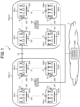
- FIG. 1 is a diagram illustrating a configuration of a network system according one embodiment of the present invention.
- a network system 1 is an electricity and communication integrated network in which a wireless communication network that includes a base station 10A, a base station 10B, and a plurality of antennas ANT and that conforms to the fifth-generation of mobile communication system (5G) and a power network that includes a plurality of direct-current grids GR11 to GRmn that are power grids are integrated.
- 5G fifth-generation of mobile communication system
- the base station 10A and the base station 10B are wireless base stations that form a 5G wireless communication network.
- 5G has features of "ultra-high speed”, “ultra-low latency", and “massive simultaneous connectivity”.
- ultra-low latency for example, one millisecond or less is ensured as communication latency.
- the standard of the wireless communication is not limited to 5G, and a communication standard for the next generation of mobile communication systems, the next generation after 5G, which is called as Beyond (B) 5G may be adopted.
- a communication standard that ensures communication latency is more preferable.
- the base station 10A forms, by the plurality of antennas ANT, a communication area CELL1 that enables communication with a wireless terminal that performs 5G wireless communication
- the base station 10B forms, by the plurality of antennas ANT, a communication area CELL2 that enables communication with a wireless terminal that performs 5G wireless communication.
- the two base stations 10A and 10B are illustrated in FIG. 1 , but the number of the base stations included in the network system 1 is not limited to two, and three or more base stations may be included.
- the plurality of antennas ANT are arranged in the communication area CELL1 and the communication area CELL2.
- the antennas ANT are distributed antennas that form the 5G wireless communication network.
- the antennas ANT have functions as radio units (RUs) in the 5G wireless communication.
- Each of the antennas ANT connected to the base station 10A by an optical fiber cable forms a small cell that enables communication with a wireless terminal, and the plurality of small cells form the communication area CELL1.
- Each of the antennas ANT connected to the base station 10B by an optical fiber cable forms a small cell that enables communication with a wireless terminal, and the plurality of small cells form the communication area CELL2.
- FIG. 2 is a schematic diagram illustrating the communication area CELL1 that corresponds to the base station 10A and small cells SCEL11 to SCEL88 that are formed by the antennas ANT connected to the base station 10A. Meanwhile, to prevent complicated illustration in the drawing, the optical fiber cable that connects each of the antennas ANT and the base station 10A is omitted in FIG. 2 .
- the communication area CELL1 is an area within a radius of one kilometer (km) centered at the base station 10A, and each of the small cells SCEL11 to SCEL88 formed by the antennas ANT is an area within a radius of 125 meters (m) centered at the antenna ANT; however, in FIG. 2 , the communication area CELL1 is represented by a bold square and each of the small cells SCEL11 to SCEL88 is represented by a dashed square by simplification.
- radio waves that are transmitted and received between the antennas ANT and wireless terminals are millimeter-wave bands, and the 64 antennas ANT are arranged in consideration of radio wave propagation, so that the 64 small cells SCEL11 to SCEL88 are formed. Meanwhile, the 64 antennas ANT are arranged and the 64 small cells SCEL11 to SCEL88 are formed for the base station 10B in the same manner.
- two-digit numbers at the ends of the reference symbols of the small cells SCEL11 to SCEL88 correspond to respective positions of the small cells SCEL11 to SCEL88 that are modeled by a matrix, where the first digits at the ends of the reference symbols correspond to positions of columns of the small cells SCEL11 to SCEL88 and the second digits at the ends of the reference symbols correspond to positions of rows of the small cells SCEL11 to SCEL88.
- the cell in the second row and the second column is referred to as the small cell SCEL22.
- buses BUS are installed in communication areas each being formed by the plurality of antennas ANT that are determined in advance.
- the bus BUS that forms a direct-current grid is a direct-current power line to which a plurality of power devices including a power generator and a power storage device are connected.
- the single bus BUS is installed in each of the communication areas each being formed by the four adjacent antennas ANT.
- direct-current grids GR11 to GRmn that are direct-current power grids are formed by the plurality of buses BUS.
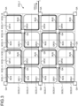
- FIG. 3 is a diagram schematically illustrating the 16 buses BUS that are arranged in the communication area CELL1, the direct-current grids GR11 to GR44 that are formed by the 16 buses BUS, and the small cells that cover the respective areas of the direct-current grids GR11 to GR44. Meanwhile, in FIG. 3 , the direct-current grids GR11 to GR44 are modeled by a matrix of m rows and n columns, and the base station 10A is omitted to prevent complicated illustration in the drawing.
- Two-digit numbers at the ends of the reference symbols of the direct-current grids GR11 to GR44 correspond to respective positions of the direct-current grids GR11 to GR44 that are modeled by a matrix of 4 rows and 4 columns, where the first digits at the ends of the reference symbols correspond to positions of columns of the direct-current grids GR11 to GR44 and the second digits at the ends of the reference symbols correspond to positions of rows of the direct-current grids GR11 to GR44.
- the direct-current grid in the second row and the second column is referred to as the direct-current grid GR22.
- Each of the direct-current grids GR11 to GR44 illustrated in FIG. 3 is one example of a bus-shaped direct-current grid.
- the buses BUS have baseline lengths of, for example, 1 km, are bent and arranged in a matrix of 4 rows and 4 columns, and form the direct-current grids GR11 to GR44.
- the buses BUS supply power at voltage of 400 volts (V), for example.
- V volts
- branch lines not illustrated
- wireless communication is covered by a communication area that is formed of the small cells in a matrix of 2 rows and 2 columns, and the bus BUS supplies power to the antennas ANT.
- the wireless communication of the direct-current grid GR11 is covered by the small cell SCEL11, the small cell SCEL12, the small cell SCEL21, and the small cell SCEL22, and the bus BUS that forms the direct-current grid GR11 supplies power to the antenna ANT that forms the small cell SCEL11, the antenna ANT that forms the small cell SCEL12, the antenna ANT that forms the small cell SCEL21, and the antenna ANT that forms the small cell SCEL22.
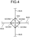
- FIG. 4 is a schematic diagram illustrating a configuration of the power gate GA.
- the power gate GA includes four DC/DC converters GCON1 to GCON4.
- the DC/DC converters GCON1 to GCON4 are configured such that one ends are connected to the single bus BUS and the other ends are connected to one another.
- the power gate GA may include a DC/DC converter that is not connected to the bus BUS, depending on a positional relationship with the direct-current grids GR11 to GR44.
- at least one of the power gates GA arranged in the single communication area is connected to the power gate GA that is arranged in the different communication area CELL2, and interchanges power across the communication areas.
- the number of the DC/DC converters included in the power gate GA may be determined in accordance with the number of the connected buses BUS.
- the power gates GA have functions of 5G wireless communication, function as wireless terminals, and perform information communication with an MEC server 101 (to be described later) via the antennas ANT.
- a cloud system 2 is a system that provides various kinds of services via a network, such as the Internet, and includes a central control device 1000.
- the central control device 1000 is connected to the base station 10A and the base station 10B.
- the central control device 1000 is a server device that has a function to control power interchange among the direct-current grids GR11 to GR44 included in the communication area CELL1 and the direct-current grids GR11 to GR44 included in the communication area CELL2.
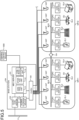
- FIG. 5 is a diagram illustrating an example of configurations of the base station 10A and the direct-current grids GR11 and GR12.
- the base station 10B has the same configuration as the base station 10A, and therefore, in FIG. 5 , the configuration of the base station 10A is illustrated as a representative and the configuration of the base station 10B is omitted. Further, in FIG. 5 , to prevent complicated illustration in the drawing, the configurations of the direct-current grids GR11 and the direct-current grid GR12 are illustrated as representatives among the direct-current grids GR11 to GR44 that are included in the communication area CELL1 corresponding to the base station 10A.
- the base station 10A includes the MEC server 101, an AC/DC converter 102, a power storage device 103, and a CU/DU 104.
- Each of the direct-current grid GR11 and the direct-current grid GR12 includes the bus BUS, converters CON1 to CON4, and power elements EL1 to EL4, and wireless communication of each of the direct-current grid GR11 and the direct-current grid GR12 is covered by a communication area that is formed of the four antennas ANT.
- the configuration of the base station 10A will be first described below.
- the AC/DC converter 102 is connected to a commercial power system 3.
- the AC/DC converter 102 converts alternating-current power supplied from the power system 3 to direct-current power, and supplies the direct-current power to the MEC server 101 and the power storage device 103.
- the power storage device 103 includes one or more power storage batteries.
- a power generator such as a renewable energy source, may be connected to the power storage device 103.
- the power that is stored in the power storage device 103 is supplied, as driving power, to the MEC server 101 and the CU/DU 104. Further, the power storage device 103 may supply power to the antennas ANT via a metal cable.
- the CU/DU 104 has a function as a central unit (CU) and a function as a distributed unit (DU) in 5G communication.
- the CU/DU 104 is connected to the plurality of antennas ANT that form the communication areas by optical fiber cables. Further, the CU/DU 104 is connected to the MEC server 101.
- the MEC server 101 that is one example of a control device is a mobile edge computing (MEC) server device that is installed at a position near a wireless terminal.
- the MEC server 101 includes a control unit 111, a storage unit 112, and a communication unit 113.
- the control unit 111 performs various kinds of arithmetic processing for implementing functions of the MEC server 101, and includes a processor, such as a central processing unit (CPU), an application specific integrated circuit (ASIC), a field-programmable gate array (FPGA), a digital signal processor (DSP), or a graphics processing unit (GPU). Functions of the control unit 111 are implemented by causing the control unit 111 to read various programs from the storage unit 112 and execute the various programs.
- a processor such as a central processing unit (CPU), an application specific integrated circuit (ASIC), a field-programmable gate array (FPGA), a digital signal processor (DSP), or a graphics processing unit (GPU).
- Functions of the control unit 111 are implemented by causing the control unit 111 to read various programs from the storage unit 112 and execute the various programs.
- control unit 111 reads various programs from the storage unit 112 and executes the various programs, so that a function to perform information communication with the converters CON1 to CON4 and the power elements EL1 to EL4 and integrally manage states of the direct-current grids GR11 to GR44 installed in the communication area CELL1, a function to integrally control the converters CON1 to CON4, a function to interchange power among the direct-current grids GR11 to GR44, a function to control power interchange with the direct-current grids installed in an adjacent communication area in accordance with an instruction given by the central control device 1000, and the like are implemented.
- the storage unit 112 includes, for example, a read only memory (ROM) for storing various programs, data, and the like that are used by the control unit 111 to perform arithmetic processing. Further, the storage unit 112 includes, for example, a random access memory (RAM) that is used as an operating space by the control unit 111 to perform arithmetic processing or that is used to store results of the arithmetic processing performed by the control unit 111.
- the storage unit 112 may include an auxiliary storage device, such as a hard disk drive (HDD) or a solid state drive (SSD).
- HDD hard disk drive
- SSD solid state drive
- the communication unit 113 includes a communication module that performs information communication in a wired or wireless manner.
- the communication unit 113 is connected to the central control device 1000.
- the communication unit 113 performs information communication with the central control device 1000 via the Internet.
- the power element EL1 is, as one example, a stationary power storage device that is able to supply, consume, and charge power, and is connected to the converter CON1.
- the stationary power storage device is one example of an in-facility power storage device that is permanently installed.
- the converter CON1 has a function to convert voltage of direct-current power supplied by the power element EL1 and output the converted one to the bus BUS and a function to convert voltage of direct-current power supplied by the bus BUS and output the converted one to the power element EL1 for charging.
- the power element EL2 is, as one example, a solar power generation device that is able to generate and supply power, and is connected to the converter CON2.
- the solar power generation device is one example of a power generation device that generates power by using renewable energy.
- the converter CON2 has a function to convert voltage of direct-current power supplied by the power element EL2 and output the converted one to the bus BUS.
- the power element EL2 is not limited to the solar power generation device, but may be a renewable source, such as a wind power generator or a geothermal power generator.
- the converter CON2 may perform control of a maximum power point tracking (MPPT) system such that if electric power corresponding to a power generation amount is input from the power element EL2, operation is performed so that output power to the bus BUS at the power generation amount is maximum.
- MPPT maximum power point tracking
- the power element EL3 is, as one example, an in-vehicle power storage device that is able to supply, consume, and charge power, and is connected to the converter CON3.
- the in-vehicle power storage device is one example of a non-stationary power storage device that is installed in the electric vehicle EV and moves.
- the converter CON3 has a function to convert voltage of direct-current power supplied by the power element EL3 and output the converted one to the bus BUS and a function to convert voltage of direct-current power supplied by the bus BUS and output the converted one to the power element EL3 for charging.
- the converter CON3 is installed in, for example, a charging station or a home charging facility, but may be installed in the electric vehicle EV.
- the power element EL4 is, as one example, a net zero energy house (ZEH) that is able to supply, consume, and charge electric power, and is connected to the converter CON4.
- the ZEH includes, for example, a solar power generation device, a power storage battery, electrical appliance, such as an air conditioner or a refrigerator, that is a power load, and the like.
- the converter CON4 has a function to convert voltage of direct-current power supplied by the power element EL4 and output the converted one to the bus BUS and a function to convert voltage of direct-current power supplied by the bus BUS and output the converted one to the power element EL4 for charging a power storage battery.
- the converters CON1 to CON4 include sensors for measuring electrical characteristic values of the buses BUS, and measures, as the electrical characteristic values, current values, voltage values, electric power values, and the like of the buses BUS, for example.
- the converters CON1 to CON4 and the power elements EL1 to EL4 are examples of a power device. Further, each of the converters CON1 to CON4 and the power elements EL1 to EL4 also functions as a wireless terminal with a function for 5G wireless communication, and performs information communication with the MEC server 101 via the single antenna ANT.
- the power elements EL1 to EL4 transmit information on power generation capacities, power generation states, power storage capacities, power storage states, power loads, and the like to the MEC server 101, and the converters CON1 to CON4 transmit the measured electric characteristic values to the MEC server 101. Furthermore, for example, if the power element EL1 is located in the small cell SCEL11 and the power element EL2 is located in the small cell SCEL12, the power element EL1 performs communication via the antenna ANT that forms the small cell SCEL11 and the power element EL2 performs communication via the antenna ANT that forms the small cell SCEL12.
- each of the converters CON1 to CON4 in the direct-current grids GR11 to GR44 is controlled by an energy management system (EMS).
- the EMS may have the same hardware configuration as the MEC server 101.
- the EMS is one example of a control device.
- the EMS is arranged in accordance with each of the direct-current grids GR11 to GR44, for example.
- the EMS may be arranged in the MEC server 101 in a virtualized manner.
- the EMS controls the converters CON1 to CON4 such that power in the buses BUS is smoothed in accordance with reception of power with respect to the power elements EL1 to EL4.
- the EMS when power shortage occurs in a certain direct-current grid installed in the communication area CELL1, and if a different direct-current grid installed in the same communication area CELL1 has excess power, the EMS that has received distributed information on neighboring direct-current grids from the MEC server 101 controls the power gate GA, so that power is supplied from the different direct-current grid to the certain direct-current grid in which power shortage has occurred.
- the EMS that is arranged for each of the direct-current grids controls the power gate GA for the direct-current grid in which power shortage has occurred among neighboring direct-current grids based on information distributed by the MEC server 101, and supplies power to the direct-current grid in which power shortage has occurred.
- the MEC server 101 may identify the direct-current grid in which power shortage has occurred based on, for example, the acquired electric characteristic value of each of the buses BUS of the direct-current grids GR11 to GR44, and control the power gate GA such that power is supplied to the identified direct-current grid.
- the control of interchanging power among the plurality of direct-current grids that are located adjacent to one another is one example of autonomous distributed cooperative control.
- the EMS communicates with the power gate GA1 and controls the power gate GA1 such that the DC/DC converter GCON1 and the DC/DC converter GCON3 of the power gate GA1 are opened. Furthermore, the EMS communicates with the power gate GA2, and controls the power gate GA2 such that voltage of the DC/DC converter GCON1 of the power gate GA2 at the side of the DC/DC converter GCON3 is increased as compared to voltage of the DC/DC converter GCON3 of the power gate GA2 at the side of the DC/DC converter GCON1.
- the EMS controls the power gate GA2 such that voltage of the DC/DC converter GCON1 of the power gate GA2 at the side of the DC/DC converter GCON3 is increased as compared to voltage of the DC/DC converter GCON3 of the power gate GA2 at the side of the DC/DC converter GCON1.
- the EMS controls the power gate GA1 such that voltage of the DC/DC converter GCON1 of the power gate GA1 at the side of the DC/DC converter GCON3 is increased as compared to voltage of the DC/DC converter GCON3 of the power gate GA1 at the side of the DC/DC converter GCON1.
- the other distributed antennas in which failures have not occurred are operating, so that it may be possible to reconnect to the other distributed antennas in which failures have not occurred and return the power elements EL1 to EL4 and the converters CON1 to CON4 to the wireless communication network at an early stage.
- the MEC server 101 may acquire information on power conditions (power generation capacities, power generation states, power storage capacities, power storage states, and power loads) or electric characteristic values from the different MEC servers 101 that are located nearby, and the EMSs may control the power gates GA such that power is interchanged in a group of a plurality of direct-current grids that are located nearby based on the acquired information.
- the control of power interchange in the group of a plurality of direct-current grids located nearby is one example of autonomous distributed cooperative control.
- the power supply and demand smoothing control in the direct-current grids GR11 to GR44 installed in the communication area does not effectively function in some cases if a balance of power supply and demand exceeds a certain limit.
- the MEC server 101 or the EMS causes each of the converters CON1 to CON4 in the direct-current grids GR11 to GR44 to operate so as to smooth power supply and demand, if power generation amounts, power consumption amounts, power load variation amounts, or the like that are adjustable by the direct-current grids GR11 to GR44 are exceeded, there is a need to interchange power exceeding a range that can be supplied by the direct-current grids GR11 to GR44.
- the central control device 1000 determines that the autonomous distributed cooperative control is not effectively implemented, power interchange is changed from the autonomous distributed cooperative control that is performed by the MEC server 101 or the EMS to centralized control in which the central control device 1000 controls power interchange between direct-current grid groups or between a plurality of direct-current grid groups that are located close to one another and a different direct-current grid group.
- the central control device 1000 controls power interchange from one of the communication area CELL1 and the communication area CELL2 to the other one of the communication area CELL1 and the communication area CELL2.
- the central control device 1000 controls the MEC server 101 of the base station 10A and the MEC server 101 of the base station 10B, and power is given from the certain direct-current grid to the direct-current grid in which power shortage has occurred.
- the central control device 1000 acquires the information on the power generation capacities, the power generation states, the power storage capacities, the power storage states, the power loads, and the like that the MEC server 101 have acquired from the power elements EL1 to EL4, and the information on the power characteristic values of the buses BUS that are acquired from the converters CON1 to CON4.
- the central control device 1000 identifies a direct-current grid in which power shortage has occurred based on the acquired information, and gives an instruction, to the MEC server 101 of the base station 10A and the MEC server 101 of the base station 10B, to give power to the identified direct-current.
- the MEC server 101 of the base station 10A and the MEC server 101 of the base station 10B give instructions on power interchange to the EMSs of the direct-current grids GR11 to GR44 that are managed by the corresponding MEC servers, in accordance with the instruction given by the central control device 1000.
- the EMS controls the power gate GA that is located on a path from the bus BUS of the direct-current grid that supplies power to the bus BUS of the direct-current grid that receives the power among the power gates GA in the communication area. Accordingly, it is possible to realize smoothing of power supply and demand between the direct-current grids that are installed in the different communication areas.
- the present embodiment by installing, for example, a mobile base station that promptly complements the wireless communication network, even if failures occur in the antennas ANT that cover the areas of the direct-current grids GR11 to GR44, it is possible to cause the power elements EL1 to EL4 or the converters CON1 to CON4 included in the direct-current grids GR11 to GR44 to return to the wireless communication network, so that resilience is increased as compared to the power network system disclosed in Patent Literature 1. Furthermore, according to the present embodiment, even if a disaster occurs, autonomous distributed control is performed in each of the direct-current grids GR11 to GR44, so that it is possible to operate the direct-current grids GR11 to GR44.
- the base stations 10A and 10B and the direct-current grids GR11 to GR44 operate with the aid of power batteries or power generation facilities, so that it is possible to interchange power in the communication area and resilience is increased as compared to the power network system disclosed in Patent Literature 1.
- the present invention has been described above, but the present invention is not limited to the embodiments as described above and may be embodied in various different forms.
- the present invention may be implemented by modifying the above-described embodiment as described below.
- the embodiment as described above and the modifications as described below may be combined with each other.
- the present invention includes configurations made by an appropriate combination of the embodiment as described above and the modifications.
- additional advantages and modifications will readily occur to those skilled in the art. Therefore, the invention in its broader aspects is not limited to embodiment as described above and the modifications, and various modifications may be made.
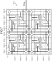
- FIG. 7 is a diagram illustrating arrangement of star-shaped direct-current grids.
- the buses BUS are arranged with straight lengths of 1 kilometer (km) and connected to branch lines BL, and the direct-current grids GR1 to GR16 are formed by the buses BUS and the branch lines BL.
- Wireless communication of each of the direct-current grids GR1 to GR16 is covered by a communication area that is formed by a small cell along the buses BUS and the branch lines BL.
- the power gates GA that interchange power among the direct-current grids are arranged among the direct-current grids. Meanwhile, the power gates GA are connected by cables that connect the power gates GA.
- Each of the direct-current grids GR1 to GR16 is one example of a star-shaped direct-current grid.
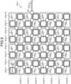
- Each of the direct-current grids GR11 to GR44 illustrated in FIG. 8 is one example of a star-shaped direct-current grid.
- the single power gate GA is arranged to interchange power with the direct-current grids in the adjacent communication area, but the number of the power gates GA is not limited to one.
- the power gates GA may be possible to arrange the power gates GA for interchanging power with the direct-current grids in the adjacent communication area in each of the buses BUS that form the direct-current grids adjacent to the direct-current grids in the adjacent communication area.
- the power gates GA that interchange power among the direct-current grids are arranged among the direct-current grids. Meanwhile, in the configuration illustrated in FIG. 9 , the single power gate GA is arranged to interchange power with the direct-current grids in the adjacent communication area, but the number of the power gates GA is not limited to one. In the communication area CELL1, it may be possible to arrange the power gates GA for interchanging power with the direct-current grids in the adjacent communication area in each of the buses BUS that form the direct-current grids adjacent to the direct-current grids in the adjacent communication area.
- the arrangement of the buses BUS is not limited to the arrangement examples illustrated in the drawings, and the bend arrangement, the straight-line arrangement, the cross-shaped arrangement, and the ring-shaped arrangement illustrated in FIGS. 3 and 7 to 9 may be combined.
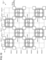
- FIG. 10 is a diagram illustrating an example of an example of arrangement of mesh-shaped direct-current grids.
- the buses BUS11 are buses that are arranged in a star-shaped manner, and the buses BUS12 are buses that are arranged in a ring-shaped manner.
- the buses BUS11 and the buses BUS12 are connected to one another, and a single direct-current grid is formed of the single bus BUS11 and the single bus BUS12. Meanwhile, areas in which the buses BUS11 and the buses BUS12 are not arranged in FIG. 10 are supplied with power from areas in which the buses BUS11 and the buses BUS12 are arranged.
- power is supplied from the bus BUS11 and the bus BUS12 that form the direct-current grid GR11 into the small cell SCEL13 and the small cell SCEL23, and power is supplied from the bus BUS11 and the bus BUS12 that form the direct-current grid GR13 into the small cell SCEL14 and the small cell SCEL24.
- the power gates GA that interchange power among the direct-current grids are arranged among the direct-current grids.
- Each of the direct-current grids illustrated in FIG. 10 is one example of a mesh-shaped direct-current grid.
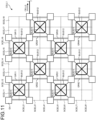
- FIG. 11 is a diagram illustrating an example of arrangement of mesh-shaped direct-current grids.
- the buses BUS11 are buses that are arranged in a star-shaped manner, and the buses BUS12 are buses that are arranged in a ring-shaped manner.
- the buses BUS11 and the buses BUS12 are connected to one another, and a single direct-current grid is formed of the single bus BUS11 and the single bus BUS12.
- the buses BUS11 are arranged along diagonal lines of the buses BUS12. Meanwhile, even in the configuration illustrated in FIG. 11 , power is supplied from the areas in which the buses BUS11 and the buses BUS12 are arranged to areas in which the buses BUS11 and the buses BUS12 are not arranged.
- power is supplied from the bus BUS11 and the bus BUS12 that form the direct-current grid GR11 into the small cell SCEL13 and the small cell SCEL23, and power is supplied from the bus BUS11 and the bus BUS12 that form the direct-current grid GR13 into the small cell SCEL14 and the small cell SCEL24.
- the power gates GA that interchange power among the direct-current grids are arranged among the direct-current grids.
- Each of the direct-current grids illustrated in FIG. 11 is one example of a mesh-shaped direct-current grid.
- the baseline lengths of the buses BUS are 1 km, but the baseline lengths are not limited to 1 km and may be shorter than 1 km or longer than 1 km. Meanwhile, if the baseline length is not equal to 1 km, the number of small cells that cover the direct-current grid that is formed by the bus BUS corresponds to the baseline length.
- the communication area CELL1 and the communication area CELL2 have certain sizes with radii of 1 km, but the communication area CELL1 and the communication area CELL2 need not always have the sizes with the radii of 1 km, and the radii may be smaller than 1 km or larger than 1 km.
- the small cells SCEL11 to SCEL88 have certain sizes with radii of 125 meters (m), but the small cells need not always have the sizes with the radii of 125 m and the radii may be smaller than 125 m or larger than 125 m.
- the power elements EL1 to EL4 and the converters CON1 to CON4 may perform wireless communication with the base stations 10A and 10B if failures occur in the antennas ANT.
- the MEC server 101 and the central control device 1000 may control the power converters connected to the power system 3 such that, in the autonomous distributed cooperative control or the centralized control as described above, power is interchanged among the direct-current grids and power is supplied from the power system 3.
- the present invention is applicable to an electricity and communication integrated network system.
Landscapes
- Engineering & Computer Science (AREA)
- Power Engineering (AREA)
- Computer Networks & Wireless Communication (AREA)
- Remote Monitoring And Control Of Power-Distribution Networks (AREA)
- Mobile Radio Communication Systems (AREA)
- Charge And Discharge Circuits For Batteries Or The Like (AREA)
- Direct Current Feeding And Distribution (AREA)
Abstract
Description
- The present invention relates to a network system and a control method of a network system.
- Smart city and compact city that realize Society 5.0 that highly integrates cyberspace and physical space of a cyber physical system (CPS) is expected to increase efficiency and sophistication of functions and services provided by cities and regions and achieve both of solution to social problems, such as decarbonization, as a society aim and economic development due to transformation of industrial structures using digital transformation or the like.
- Reflecting an increase in investing (ESG investing) that considers three factors, such as environment, social, and governance, or adoption of "the 2030 Agenda and the 17 Sustainable Development Goals (SDGs)" that was adopted in September 2015 at the United Nations Summit, the number of members of Renewable Energy 1000 (RE100) in which only companies that have claimed to perform business operation by using only renewable energy can join is increasing.
- It is estimated that a world smart city market cumulatively reaches a scale of 3100 trillion yen in 20 years from 2010 to 2030, and, in energy-related markets that play a central role, it is expected to achieve a market scale of about 720 trillion yen in relation to smart grids, a market scale of about 310 trillion yen in relation to a next-generation vehicle, such as an electric vehicle, and a market scale of about 380 trillion yen in relation to renewable energy. Therefore, smart city development plans are promoted in a large number of countries and regions, and some of the plans are already put into practice.
-
Patent Literature 1 proposes a system that connects distributed energy resources including solar power, wind-power generation, storage batteries, and power storage systems, social infrastructures including EVs and charging stations, a home energy management system (HEMS), a building energy management system (BEMS), and power plants to one another by communication grids and power grids. - Furthermore, to compensate for power shortage in the power grids, a power network system disclosed in
Patent Literature 1 is known as the invention for flexibly interchanging power among a plurality of power cells, for example. The power cells disclosed inPatent Literature 1, include loads, such as houses and buildings, power generation facilities, such as solar panels and wind generators, power storage facilities, such as storage batteries, and power routers. The power routers are connected to a bulk power system that transmits power from power routers of different power cells or power plants. The power router of each of the cells is connected to a management server via a communication network, and power is flexibly interchanged among the power cells under the control of the management server. -
- Patent Literature 1: International Publication NO.
WO2013/172088 - Patent Literature 2: International Publication NO.
WO2014/061259 - In the power network system disclosed in
Patent Literature 1, the power routers are integrally controlled, so that if a failure occurs between the power routers and the management server due to a disaster or the like, it becomes impossible to flexibly interchange power among the power cells. By adopting autonomous distributed control, it becomes possible to cope with the failure; however, it is difficult to optimize the entire system and interchange the power by only the autonomous distributed control, and therefore, a technology for increasing resilience is needed. - The present invention has been conceived in view of the foregoing situations, and an object of the present invention is to provide a technology for increasing resilience in a network in which a power network and a communication network are integrated.
- A network system according to one aspect of the present invention includes: a wireless base station configured to relay communication performed by wireless terminals; a plurality of distributed antennas each being configured to be connected to the wireless base station and form a cell that enables communication with the wireless terminals; a plurality of direct-current grids each being arranged in a predetermined form in a communication area formed by the plurality of cells and configured to interchange power with a plurality of power devices connected to the subject direct-current grid; a power gate arranged between the direct-current grids located adjacent to each other and configured to interchange power between the adjacent direct-current grids; and a control device configured to control the power gate based on information acquired from the power devices via the distributed antennas, wherein the power devices connected to the direct-current grids are configured to perform communication with the control device via the distributed antennas that form the communication area including the direct-current grids.
- The direct-current grids may be formed in a bus-shaped manner.
- The direct-current grids may be formed in a star-shaped manner.
- The direct-current grids may be formed in a ring-shaped manner.
- The direct-current grids may be formed in a mesh-shaped manner.
- The network system according to one aspect of the present invention may include a plurality of wireless base stations, the control device may be arranged for each of the wireless base stations, the network system may further include: a central control device configured to control the plurality of control devices based on information acquired from the power devices, and the control devices may be configured to control power interchange among the direct-current grids by controlling the power gates under control of the central control device.
- When the power gates interchange power, the power gates may be configured to increase voltage of the direct-current grid that supplies power as compared to voltage of the direct-current grid that receives power.
- One aspect of the present invention is a control method of a network system including: a wireless base station configured to relay communication performed by wireless terminals; a plurality of distributed antennas each being configured to be connected to the wireless base station and form a cell that enables communication with the wireless terminals; a plurality of direct-current grids each being arranged in a predetermined form in a communication area formed by the plurality of cells and configured to interchange power with a plurality of power devices connected to the subject direct-current grid; a power gate arranged between the direct-current grids located adjacent to each other and configured to interchange power between the adjacent direct-current grids; and a control device configured to control the power gate based on information acquired from the power devices via the distributed antennas, the control method including: acquiring, by the control device, information transmitted from the power devices via the distributed antennas; and controlling, by the control device, the power gates such that power interchange is performed among the direct-current grids based on the acquired information. Advantageous Effects of Invention
- A network system of the present invention includes a wireless base station that relays communication performed by wireless terminals, a plurality of distributed antennas each being connected to the wireless base station and forming a cell that enables communication with the wireless terminals, a plurality of direct-current grids each being arranged in a predetermined form in a communication area that is formed by the plurality of cells and interchanging power with a plurality of power devices connected to the subject direct-current grid, a power gate that is arranged between the direct-current grids located adjacent to each other and interchange power between the adjacent direct-current grids, and a control device that controls the power gate based on information that is acquired from the power devices via the distributed antennas. The power devices connected to the direct-current grids perform communication with the control device via the distributed antennas that form the communication area including the direct-current grids. Even if a failure occur in a certain distributed antenna due to a disaster, the other distributed antenna in which a failure has not occurred is operating, so that it is possible to cause the power devices connected to the direct-current grid to reconnect the other distributed antenna in which the failure has not occurred and it is possible restore the power devices, so that resilience is increased.
- A control method of a network system of the present invention is a control method of a network system including a wireless base station that relays communication performed by wireless terminals, a plurality of distributed antennas each being connected to the wireless base station and forming a cell that enables communication with the wireless terminals, a plurality of direct-current grids each being arranged in a predetermined form in a communication area that is formed by the plurality of cells and interchanging power with a plurality of power devices connected to the subject direct-current grid, a power gate that is arranged between the direct-current grids located adjacent to each other and interchange power between the adjacent direct-current grids, and a control device that controls the power gate based on information that is acquired from the power devices via the distributed antennas, where the control device acquires information transmitted from the power devices via the distributed antennas, and controls the power gate such that power interchange is performed among the direct-current grids based on the acquired information. Even if a failure occur in a certain distributed antenna due to a disaster, the other distributed antenna in which a failure has not occurred is operating, so that it is possible to cause the power devices connected to the direct-current grid to reconnect the other distributed antenna in which the failure has not occurred and it is possible to restore the power devices, so that resilience is increased.
-
-
FIG. 1 is a diagram illustrating a configuration of a network system according to an embodiment. -
FIG. 2 is a schematic diagram of small cells that are formed by antennas. -
FIG. 3 is a diagram schematically illustrating bus-shaped direct-current grids and small cells arranged in a communication area. -
FIG. 4 is a schematic diagram illustrating a configuration of a power gate. -
FIG. 5 is a diagram illustrating configurations of a base station and the direct-current grids. -
FIG. 6 is a diagram for explaining a method of interchanging power. -
FIG. 7 is a diagram illustrating arrangement of star-shaped direct-current grids. -
FIG. 8 is a diagram illustrating arrangement of star-shaped direct-current grids. -
FIG. 9 is a diagram illustrating arrangement of ring-shaped direct-current grids. -
FIG. 10 is a diagram illustrating arrangement of mesh-shaped direct-current grids. -
FIG. 11 is a diagram illustrating arrangement of mesh-shaped direct-current grids. - Embodiments of the present invention will be described in detail below based on the drawings. The present invention is not limited by the embodiments described below. In addition, in the description of the drawings, the same or corresponding components are appropriately denoted by the same reference symbols.
-
FIG. 1 is a diagram illustrating a configuration of a network system according one embodiment of the present invention. Anetwork system 1 is an electricity and communication integrated network in which a wireless communication network that includes abase station 10A, abase station 10B, and a plurality of antennas ANT and that conforms to the fifth-generation of mobile communication system (5G) and a power network that includes a plurality of direct-current grids GR11 to GRmn that are power grids are integrated. - The
base station 10A and thebase station 10B are wireless base stations that form a 5G wireless communication network. Meanwhile, 5G has features of "ultra-high speed", "ultra-low latency", and "massive simultaneous connectivity". As for "ultra-low latency", for example, one millisecond or less is ensured as communication latency. The standard of the wireless communication is not limited to 5G, and a communication standard for the next generation of mobile communication systems, the next generation after 5G, which is called as Beyond (B) 5G may be adopted. A communication standard that ensures communication latency is more preferable. Thebase station 10A forms, by the plurality of antennas ANT, a communication area CELL1 that enables communication with a wireless terminal that performs 5G wireless communication, and thebase station 10B forms, by the plurality of antennas ANT, a communication area CELL2 that enables communication with a wireless terminal that performs 5G wireless communication. Meanwhile, the twobase stations FIG. 1 , but the number of the base stations included in thenetwork system 1 is not limited to two, and three or more base stations may be included. - The plurality of antennas ANT are arranged in the communication area CELL1 and the communication area CELL2. The antennas ANT are distributed antennas that form the 5G wireless communication network. The antennas ANT have functions as radio units (RUs) in the 5G wireless communication. Each of the antennas ANT connected to the
base station 10A by an optical fiber cable forms a small cell that enables communication with a wireless terminal, and the plurality of small cells form the communication area CELL1. Each of the antennas ANT connected to thebase station 10B by an optical fiber cable forms a small cell that enables communication with a wireless terminal, and the plurality of small cells form the communication area CELL2. -
FIG. 2 is a schematic diagram illustrating the communication area CELL1 that corresponds to thebase station 10A and small cells SCEL11 to SCEL88 that are formed by the antennas ANT connected to thebase station 10A. Meanwhile, to prevent complicated illustration in the drawing, the optical fiber cable that connects each of the antennas ANT and thebase station 10A is omitted inFIG. 2 . - For example, the communication area CELL1 is an area within a radius of one kilometer (km) centered at the
base station 10A, and each of the small cells SCEL11 to SCEL88 formed by the antennas ANT is an area within a radius of 125 meters (m) centered at the antenna ANT; however, inFIG. 2 , the communication area CELL1 is represented by a bold square and each of the small cells SCEL11 to SCEL88 is represented by a dashed square by simplification. In the present embodiment, it is assumed that radio waves that are transmitted and received between the antennas ANT and wireless terminals are millimeter-wave bands, and the 64 antennas ANT are arranged in consideration of radio wave propagation, so that the 64 small cells SCEL11 to SCEL88 are formed. Meanwhile, the 64 antennas ANT are arranged and the 64 small cells SCEL11 to SCEL88 are formed for thebase station 10B in the same manner. - Meanwhile, two-digit numbers at the ends of the reference symbols of the small cells SCEL11 to SCEL88 correspond to respective positions of the small cells SCEL11 to SCEL88 that are modeled by a matrix, where the first digits at the ends of the reference symbols correspond to positions of columns of the small cells SCEL11 to SCEL88 and the second digits at the ends of the reference symbols correspond to positions of rows of the small cells SCEL11 to SCEL88. For example, in
FIG. 2 , the cell in the second row and the second column is referred to as the small cell SCEL22. - Referring back to
FIG. 1 , in the communication area CELL1 and the communication area CELL2, buses BUS are installed in communication areas each being formed by the plurality of antennas ANT that are determined in advance. The bus BUS that forms a direct-current grid is a direct-current power line to which a plurality of power devices including a power generator and a power storage device are connected. In the present embodiment, the single bus BUS is installed in each of the communication areas each being formed by the four adjacent antennas ANT. In the communication area CELL1 and the communication area CELL2, direct-current grids GR11 to GRmn that are direct-current power grids are formed by the plurality of buses BUS. -
FIG. 3 is a diagram schematically illustrating the 16 buses BUS that are arranged in the communication area CELL1, the direct-current grids GR11 to GR44 that are formed by the 16 buses BUS, and the small cells that cover the respective areas of the direct-current grids GR11 to GR44. Meanwhile, inFIG. 3 , the direct-current grids GR11 to GR44 are modeled by a matrix of m rows and n columns, and thebase station 10A is omitted to prevent complicated illustration in the drawing. Two-digit numbers at the ends of the reference symbols of the direct-current grids GR11 to GR44 correspond to respective positions of the direct-current grids GR11 to GR44 that are modeled by a matrix of 4 rows and 4 columns, where the first digits at the ends of the reference symbols correspond to positions of columns of the direct-current grids GR11 to GR44 and the second digits at the ends of the reference symbols correspond to positions of rows of the direct-current grids GR11 to GR44. For example, inFIG. 3 , the direct-current grid in the second row and the second column is referred to as the direct-current grid GR22. Each of the direct-current grids GR11 to GR44 illustrated inFIG. 3 is one example of a bus-shaped direct-current grid. - The buses BUS have baseline lengths of, for example, 1 km, are bent and arranged in a matrix of 4 rows and 4 columns, and form the direct-current grids GR11 to GR44. The buses BUS supply power at voltage of 400 volts (V), for example. Meanwhile, in
FIG. 3 , in areas of the small cells in which the buses BUS are not located, power is supplied by branch lines (not illustrated) that are extended from the buses BUS, for example. In each of the direct-current grids GR11 to GR44, wireless communication is covered by a communication area that is formed of the small cells in a matrix of 2 rows and 2 columns, and the bus BUS supplies power to the antennas ANT. For example, the wireless communication of the direct-current grid GR11 is covered by the small cell SCEL11, the small cell SCEL12, the small cell SCEL21, and the small cell SCEL22, and the bus BUS that forms the direct-current grid GR11 supplies power to the antenna ANT that forms the small cell SCEL11, the antenna ANT that forms the small cell SCEL12, the antenna ANT that forms the small cell SCEL21, and the antenna ANT that forms the small cell SCEL22. - Power gates GA that interchange power among the direct-current grids is arranged among the direct-current grids.
FIG. 4 is a schematic diagram illustrating a configuration of the power gate GA. The power gate GA includes four DC/DC converters GCON1 to GCON4. The DC/DC converters GCON1 to GCON4 are configured such that one ends are connected to the single bus BUS and the other ends are connected to one another. Meanwhile, the power gate GA may include a DC/DC converter that is not connected to the bus BUS, depending on a positional relationship with the direct-current grids GR11 to GR44. Further, at least one of the power gates GA arranged in the single communication area is connected to the power gate GA that is arranged in the different communication area CELL2, and interchanges power across the communication areas. Meanwhile, the number of the DC/DC converters included in the power gate GA may be determined in accordance with the number of the connected buses BUS. The power gates GA have functions of 5G wireless communication, function as wireless terminals, and perform information communication with an MEC server 101 (to be described later) via the antennas ANT. - Referring back to
FIG. 1 , acloud system 2 is a system that provides various kinds of services via a network, such as the Internet, and includes acentral control device 1000. Thecentral control device 1000 is connected to thebase station 10A and thebase station 10B. Thecentral control device 1000 is a server device that has a function to control power interchange among the direct-current grids GR11 to GR44 included in the communication area CELL1 and the direct-current grids GR11 to GR44 included in the communication area CELL2. -
FIG. 5 is a diagram illustrating an example of configurations of thebase station 10A and the direct-current grids GR11 and GR12. Meanwhile, thebase station 10B has the same configuration as thebase station 10A, and therefore, inFIG. 5 , the configuration of thebase station 10A is illustrated as a representative and the configuration of thebase station 10B is omitted. Further, inFIG. 5 , to prevent complicated illustration in the drawing, the configurations of the direct-current grids GR11 and the direct-current grid GR12 are illustrated as representatives among the direct-current grids GR11 to GR44 that are included in the communication area CELL1 corresponding to thebase station 10A. - The
base station 10A includes theMEC server 101, an AC/DC converter 102, apower storage device 103, and a CU/DU 104. Each of the direct-current grid GR11 and the direct-current grid GR12 includes the bus BUS, converters CON1 to CON4, and power elements EL1 to EL4, and wireless communication of each of the direct-current grid GR11 and the direct-current grid GR12 is covered by a communication area that is formed of the four antennas ANT. - The configuration of the
base station 10A will be first described below. The AC/DC converter 102 is connected to a commercial power system 3. The AC/DC converter 102 converts alternating-current power supplied from the power system 3 to direct-current power, and supplies the direct-current power to theMEC server 101 and thepower storage device 103. - The
power storage device 103 includes one or more power storage batteries. A power generator, such as a renewable energy source, may be connected to thepower storage device 103. The power that is stored in thepower storage device 103 is supplied, as driving power, to theMEC server 101 and the CU/DU 104. Further, thepower storage device 103 may supply power to the antennas ANT via a metal cable. - The CU/
DU 104 has a function as a central unit (CU) and a function as a distributed unit (DU) in 5G communication. The CU/DU 104 is connected to the plurality of antennas ANT that form the communication areas by optical fiber cables. Further, the CU/DU 104 is connected to theMEC server 101. - The
MEC server 101 that is one example of a control device is a mobile edge computing (MEC) server device that is installed at a position near a wireless terminal. TheMEC server 101 includes a control unit 111, a storage unit 112, and acommunication unit 113. - The control unit 111 performs various kinds of arithmetic processing for implementing functions of the
MEC server 101, and includes a processor, such as a central processing unit (CPU), an application specific integrated circuit (ASIC), a field-programmable gate array (FPGA), a digital signal processor (DSP), or a graphics processing unit (GPU). Functions of the control unit 111 are implemented by causing the control unit 111 to read various programs from the storage unit 112 and execute the various programs. For example, the control unit 111 reads various programs from the storage unit 112 and executes the various programs, so that a function to perform information communication with the converters CON1 to CON4 and the power elements EL1 to EL4 and integrally manage states of the direct-current grids GR11 to GR44 installed in the communication area CELL1, a function to integrally control the converters CON1 to CON4, a function to interchange power among the direct-current grids GR11 to GR44, a function to control power interchange with the direct-current grids installed in an adjacent communication area in accordance with an instruction given by thecentral control device 1000, and the like are implemented. - The storage unit 112 includes, for example, a read only memory (ROM) for storing various programs, data, and the like that are used by the control unit 111 to perform arithmetic processing. Further, the storage unit 112 includes, for example, a random access memory (RAM) that is used as an operating space by the control unit 111 to perform arithmetic processing or that is used to store results of the arithmetic processing performed by the control unit 111. The storage unit 112 may include an auxiliary storage device, such as a hard disk drive (HDD) or a solid state drive (SSD).
- The
communication unit 113 includes a communication module that performs information communication in a wired or wireless manner. Thecommunication unit 113 is connected to thecentral control device 1000. Thecommunication unit 113 performs information communication with thecentral control device 1000 via the Internet. - The configurations of the direct-current grids GR11 and GR12 will be described below. The power element EL1 is, as one example, a stationary power storage device that is able to supply, consume, and charge power, and is connected to the converter CON1. The stationary power storage device is one example of an in-facility power storage device that is permanently installed. The converter CON1 has a function to convert voltage of direct-current power supplied by the power element EL1 and output the converted one to the bus BUS and a function to convert voltage of direct-current power supplied by the bus BUS and output the converted one to the power element EL1 for charging.
- The power element EL2 is, as one example, a solar power generation device that is able to generate and supply power, and is connected to the converter CON2. The solar power generation device is one example of a power generation device that generates power by using renewable energy. The converter CON2 has a function to convert voltage of direct-current power supplied by the power element EL2 and output the converted one to the bus BUS. Meanwhile, the power element EL2 is not limited to the solar power generation device, but may be a renewable source, such as a wind power generator or a geothermal power generator. Meanwhile, if the power element EL2 is an element, such as the solar power generation device, for which a power generation amount is not controlled from the viewpoint of efficiency, the converter CON2 may perform control of a maximum power point tracking (MPPT) system such that if electric power corresponding to a power generation amount is input from the power element EL2, operation is performed so that output power to the bus BUS at the power generation amount is maximum.
- The power element EL3 is, as one example, an in-vehicle power storage device that is able to supply, consume, and charge power, and is connected to the converter CON3. The in-vehicle power storage device is one example of a non-stationary power storage device that is installed in the electric vehicle EV and moves. The converter CON3 has a function to convert voltage of direct-current power supplied by the power element EL3 and output the converted one to the bus BUS and a function to convert voltage of direct-current power supplied by the bus BUS and output the converted one to the power element EL3 for charging. The converter CON3 is installed in, for example, a charging station or a home charging facility, but may be installed in the electric vehicle EV.
- The power element EL4 is, as one example, a net zero energy house (ZEH) that is able to supply, consume, and charge electric power, and is connected to the converter CON4. The ZEH includes, for example, a solar power generation device, a power storage battery, electrical appliance, such as an air conditioner or a refrigerator, that is a power load, and the like. The converter CON4 has a function to convert voltage of direct-current power supplied by the power element EL4 and output the converted one to the bus BUS and a function to convert voltage of direct-current power supplied by the bus BUS and output the converted one to the power element EL4 for charging a power storage battery.
- The converters CON1 to CON4 include sensors for measuring electrical characteristic values of the buses BUS, and measures, as the electrical characteristic values, current values, voltage values, electric power values, and the like of the buses BUS, for example. The converters CON1 to CON4 and the power elements EL1 to EL4 are examples of a power device. Further, each of the converters CON1 to CON4 and the power elements EL1 to EL4 also functions as a wireless terminal with a function for 5G wireless communication, and performs information communication with the
MEC server 101 via the single antenna ANT. For example, the power elements EL1 to EL4 transmit information on power generation capacities, power generation states, power storage capacities, power storage states, power loads, and the like to theMEC server 101, and the converters CON1 to CON4 transmit the measured electric characteristic values to theMEC server 101. Furthermore, for example, if the power element EL1 is located in the small cell SCEL11 and the power element EL2 is located in the small cell SCEL12, the power element EL1 performs communication via the antenna ANT that forms the small cell SCEL11 and the power element EL2 performs communication via the antenna ANT that forms the small cell SCEL12. - Moreover, each of the converters CON1 to CON4 in the direct-current grids GR11 to GR44 is controlled by an energy management system (EMS). The EMS may have the same hardware configuration as the
MEC server 101. The EMS is one example of a control device. The EMS is arranged in accordance with each of the direct-current grids GR11 to GR44, for example. The EMS may be arranged in theMEC server 101 in a virtualized manner. The EMS controls the converters CON1 to CON4 such that power in the buses BUS is smoothed in accordance with reception of power with respect to the power elements EL1 to EL4. In the direct-current grids GR11 to GR44, power generation capacities, power generation states, power storage capacities, power storage states, power loads, and the electric characteristic values of the buses BUS vary from moment to moment; however, each of the EMSs controls each of the converters CON1 to CON4 in the direct-current grids GR11 to GR44, so that it is possible to cancel out the variation, it is possible to smooth power in the buses BUS, and it is possible to stabilize power supply and demand in each of the direct-current grids GR11 to GR44. Meanwhile, as a control method in the direct-current grids GR11 to GR44, for example, various control methods, such as feedback control, are applicable. - Furthermore, in the present embodiment, when power shortage occurs in a certain direct-current grid installed in the communication area CELL1, and if a different direct-current grid installed in the same communication area CELL1 has excess power, the EMS that has received distributed information on neighboring direct-current grids from the
MEC server 101 controls the power gate GA, so that power is supplied from the different direct-current grid to the certain direct-current grid in which power shortage has occurred. The EMS that is arranged for each of the direct-current grids controls the power gate GA for the direct-current grid in which power shortage has occurred among neighboring direct-current grids based on information distributed by theMEC server 101, and supplies power to the direct-current grid in which power shortage has occurred. Meanwhile, in the present embodiment, theMEC server 101 may identify the direct-current grid in which power shortage has occurred based on, for example, the acquired electric characteristic value of each of the buses BUS of the direct-current grids GR11 to GR44, and control the power gate GA such that power is supplied to the identified direct-current grid. The control of interchanging power among the plurality of direct-current grids that are located adjacent to one another is one example of autonomous distributed cooperative control. -
FIG. 6 is a diagram for explaining a method of interchanging power via the power gates GA. The buses BUS1 to BUS3 are direct-current power lines that constitute the direct-current grids as described above. The power gate GA1 is a power gate that is installed between the bus BUS1 and the bus BUS2, and the power gate GA2 is a power gate that is installed between the bus BUS2 and the bus BUS3. - For example, if power is given from the bus BUS2 to the bus BUS3, the EMS communicates with the power gate GA1 and controls the power gate GA1 such that the DC/DC converter GCON1 and the DC/DC converter GCON3 of the power gate GA1 are opened. Furthermore, the EMS communicates with the power gate GA2, and controls the power gate GA2 such that voltage of the DC/DC converter GCON1 of the power gate GA2 at the side of the DC/DC converter GCON3 is increased as compared to voltage of the DC/DC converter GCON3 of the power gate GA2 at the side of the DC/DC converter GCON1. By controlling the power gate GA1 and the power gate GA2 as described above, a path between the bus BUS1 and the bus BUS2 is blocked and power is given from the bus BUS2 to the bus BUS3.
- Furthermore, for example, if power is given from the bus BUS1 to the bus BUS3, the EMS controls the power gate GA2 such that voltage of the DC/DC converter GCON1 of the power gate GA2 at the side of the DC/DC converter GCON3 is increased as compared to voltage of the DC/DC converter GCON3 of the power gate GA2 at the side of the DC/DC converter GCON1. Moreover, the EMS controls the power gate GA1 such that voltage of the DC/DC converter GCON1 of the power gate GA1 at the side of the DC/DC converter GCON3 is increased as compared to voltage of the DC/DC converter GCON3 of the power gate GA1 at the side of the DC/DC converter GCON1. By controlling the power gate GA1 and the power gate GA2 as described above, power is given from the bus BUS1 to the bus BUS3 via the bus BUS2, so that it is possible to give power across the direct-current grids and it is possible to smooth power supply and demand in a region of communication areas controlled by the
single MEC server 101. - Meanwhile, if failures occur in the antennas ANT due to, for example, a disaster, it becomes difficult to acquire information from the power elements EL1 to EL4 and the converters CON1 to CON4 via the antennas ANT. In this case, for example, by sending a mobile base station in the form of a vehicle, it is possible to return the power elements EL1 to EL4 and the converters CON1 to CON4 to the wireless communication network at an early stage, and the EMS is able to acquire information from the power elements EL1 to EL4 and the converters CON1 to CON4 and interchange power among the direct-current grids. Furthermore, the other distributed antennas in which failures have not occurred are operating, so that it may be possible to reconnect to the other distributed antennas in which failures have not occurred and return the power elements EL1 to EL4 and the converters CON1 to CON4 to the wireless communication network at an early stage.
- Moreover, in the present embodiment, the
MEC server 101 may acquire information on power conditions (power generation capacities, power generation states, power storage capacities, power storage states, and power loads) or electric characteristic values from thedifferent MEC servers 101 that are located nearby, and the EMSs may control the power gates GA such that power is interchanged in a group of a plurality of direct-current grids that are located nearby based on the acquired information. The control of power interchange in the group of a plurality of direct-current grids located nearby is one example of autonomous distributed cooperative control. - Meanwhile, the power supply and demand smoothing control in the direct-current grids GR11 to GR44 installed in the communication area does not effectively function in some cases if a balance of power supply and demand exceeds a certain limit. For example, even when the
MEC server 101 or the EMS causes each of the converters CON1 to CON4 in the direct-current grids GR11 to GR44 to operate so as to smooth power supply and demand, if power generation amounts, power consumption amounts, power load variation amounts, or the like that are adjustable by the direct-current grids GR11 to GR44 are exceeded, there is a need to interchange power exceeding a range that can be supplied by the direct-current grids GR11 to GR44. - If the
central control device 1000 determines that the autonomous distributed cooperative control is not effectively implemented, power interchange is changed from the autonomous distributed cooperative control that is performed by theMEC server 101 or the EMS to centralized control in which thecentral control device 1000 controls power interchange between direct-current grid groups or between a plurality of direct-current grid groups that are located close to one another and a different direct-current grid group. In the case of the centralized control as described above, in thenetwork system 1, thecentral control device 1000 controls power interchange from one of the communication area CELL1 and the communication area CELL2 to the other one of the communication area CELL1 and the communication area CELL2. Specifically, when power shortage occurs in a certain direct-current grid that is installed in the communication area CELL1 or the communication area CELL2, and if a certain direct-current grid installed in one of the communication areas has excess power capacity, thecentral control device 1000 controls theMEC server 101 of thebase station 10A and theMEC server 101 of thebase station 10B, and power is given from the certain direct-current grid to the direct-current grid in which power shortage has occurred. - For example, the
central control device 1000 acquires the information on the power generation capacities, the power generation states, the power storage capacities, the power storage states, the power loads, and the like that theMEC server 101 have acquired from the power elements EL1 to EL4, and the information on the power characteristic values of the buses BUS that are acquired from the converters CON1 to CON4. Thecentral control device 1000 identifies a direct-current grid in which power shortage has occurred based on the acquired information, and gives an instruction, to theMEC server 101 of thebase station 10A and theMEC server 101 of thebase station 10B, to give power to the identified direct-current. TheMEC server 101 of thebase station 10A and theMEC server 101 of thebase station 10B give instructions on power interchange to the EMSs of the direct-current grids GR11 to GR44 that are managed by the corresponding MEC servers, in accordance with the instruction given by thecentral control device 1000. The EMS controls the power gate GA that is located on a path from the bus BUS of the direct-current grid that supplies power to the bus BUS of the direct-current grid that receives the power among the power gates GA in the communication area. Accordingly, it is possible to realize smoothing of power supply and demand between the direct-current grids that are installed in the different communication areas. - According to the present embodiment, by installing, for example, a mobile base station that promptly complements the wireless communication network, even if failures occur in the antennas ANT that cover the areas of the direct-current grids GR11 to GR44, it is possible to cause the power elements EL1 to EL4 or the converters CON1 to CON4 included in the direct-current grids GR11 to GR44 to return to the wireless communication network, so that resilience is increased as compared to the power network system disclosed in
Patent Literature 1. Furthermore, according to the present embodiment, even if a disaster occurs, autonomous distributed control is performed in each of the direct-current grids GR11 to GR44, so that it is possible to operate the direct-current grids GR11 to GR44. Moreover, according to the present embodiment, even if a disaster occurs, thebase stations Patent Literature 1. - Thus, the embodiment of the present invention has been described above, but the present invention is not limited to the embodiments as described above and may be embodied in various different forms. For example, the present invention may be implemented by modifying the above-described embodiment as described below. Meanwhile, the embodiment as described above and the modifications as described below may be combined with each other. The present invention includes configurations made by an appropriate combination of the embodiment as described above and the modifications. Furthermore, additional advantages and modifications will readily occur to those skilled in the art. Therefore, the invention in its broader aspects is not limited to embodiment as described above and the modifications, and various modifications may be made.
-
FIG. 7 is a diagram illustrating arrangement of star-shaped direct-current grids. In a configuration illustrated inFIG. 7 , the buses BUS are arranged with straight lengths of 1 kilometer (km) and connected to branch lines BL, and the direct-current grids GR1 to GR16 are formed by the buses BUS and the branch lines BL. Wireless communication of each of the direct-current grids GR1 to GR16 is covered by a communication area that is formed by a small cell along the buses BUS and the branch lines BL. Even in the configuration illustrated inFIG. 7 , the power gates GA that interchange power among the direct-current grids are arranged among the direct-current grids. Meanwhile, the power gates GA are connected by cables that connect the power gates GA. Each of the direct-current grids GR1 to GR16 is one example of a star-shaped direct-current grid. -
FIG. 8 is a diagram illustrating arrangement of star-shaped direct-current grids. In a configuration illustrated inFIG. 8 , the buses BUS are arranged in star shapes and entire lengths are 1 km. In the configuration illustrated inFIG. 8 , the buses BUS are arranged in a matrix of four rows and four columns in the communication area CELL1 and form the direct-current grids GR11 to GR44. Wireless communication of each of the direct-current grids GR11 to GR44 is covered by a communication area formed by small cells in a matrix of two rows and two columns. Even in the configuration illustrated inFIG. 8 , the power gates GA that interchange power among the direct-current grids are arranged among the direct-current grids. Each of the direct-current grids GR11 to GR44 illustrated inFIG. 8 is one example of a star-shaped direct-current grid. Meanwhile, in the configuration illustrated inFIG. 8 , the single power gate GA is arranged to interchange power with the direct-current grids in the adjacent communication area, but the number of the power gates GA is not limited to one. In the communication area CELL1, it may be possible to arrange the power gates GA for interchanging power with the direct-current grids in the adjacent communication area in each of the buses BUS that form the direct-current grids adjacent to the direct-current grids in the adjacent communication area. -
FIG. 9 is a diagram illustrating arrangement of ring-shaped direct-current grids. In a configuration illustrated inFIG. 9 , the buses BUS are arranged in ring shapes and entire lengths are 1 km. In the configuration illustrated inFIG. 9 , the buses B are arranged in a matrix of eight rows and eight columns in the communication area CELL1 and form the direct-current grids GR11 to GR84. Wireless communication of each of the direct-current grids GR11 to GR84 is covered by a communication area formed by small cells in a matrix of one row and two columns. Each of the direct-current grids GR11 to GR84 illustrated inFIG. 9 is one example of a ring-shaped direct-current grid. Even in the configuration illustrated inFIG. 9 , the power gates GA that interchange power among the direct-current grids are arranged among the direct-current grids. Meanwhile, in the configuration illustrated inFIG. 9 , the single power gate GA is arranged to interchange power with the direct-current grids in the adjacent communication area, but the number of the power gates GA is not limited to one. In the communication area CELL1, it may be possible to arrange the power gates GA for interchanging power with the direct-current grids in the adjacent communication area in each of the buses BUS that form the direct-current grids adjacent to the direct-current grids in the adjacent communication area. - Even in the configurations illustrated in
FIG. 7 to 9 , even if a disaster occurs, autonomous distributed control is performed in each of the direct-current grids, so that it is possible to operate the direct-current grids and interchange power in the communication area. Furthermore, by installing, for example, a mobile base station that promptly complements the wireless communication network, even if failures occur in the antennas ANT that cover the areas of the direct-current grids, for example, it is possible to cause the power elements EL1 to EL4 or the converters CON1 to CON4 included in the direct-current grids to return to the wireless communication network. Meanwhile, the arrangement of the buses BUS is not limited to the arrangement examples illustrated in the drawings, and the bend arrangement, the straight-line arrangement, the cross-shaped arrangement, and the ring-shaped arrangement illustrated inFIGS. 3 and7 to 9 may be combined. For example, it may be possible to form a mesh-shaped direct-current grid by combining the straight-line arrangement and the cross-shaped arrangement, or it may be possible to form a mesh-shaped direct-current grid by combining the straight-line arrangement. -
FIG. 10 is a diagram illustrating an example of an example of arrangement of mesh-shaped direct-current grids. The buses BUS11 are buses that are arranged in a star-shaped manner, and the buses BUS12 are buses that are arranged in a ring-shaped manner. The buses BUS11 and the buses BUS12 are connected to one another, and a single direct-current grid is formed of the single bus BUS11 and the single bus BUS12. Meanwhile, areas in which the buses BUS11 and the buses BUS12 are not arranged inFIG. 10 are supplied with power from areas in which the buses BUS11 and the buses BUS12 are arranged. For example, power is supplied from the bus BUS11 and the bus BUS12 that form the direct-current grid GR11 into the small cell SCEL13 and the small cell SCEL23, and power is supplied from the bus BUS11 and the bus BUS12 that form the direct-current grid GR13 into the small cell SCEL14 and the small cell SCEL24. Even in the configuration illustrated inFIG. 10 , the power gates GA that interchange power among the direct-current grids are arranged among the direct-current grids. Each of the direct-current grids illustrated inFIG. 10 is one example of a mesh-shaped direct-current grid. -
FIG. 11 is a diagram illustrating an example of arrangement of mesh-shaped direct-current grids. The buses BUS11 are buses that are arranged in a star-shaped manner, and the buses BUS12 are buses that are arranged in a ring-shaped manner. The buses BUS11 and the buses BUS12 are connected to one another, and a single direct-current grid is formed of the single bus BUS11 and the single bus BUS12. In the configuration illustrated inFIG. 11 , the buses BUS11 are arranged along diagonal lines of the buses BUS12. Meanwhile, even in the configuration illustrated inFIG. 11 , power is supplied from the areas in which the buses BUS11 and the buses BUS12 are arranged to areas in which the buses BUS11 and the buses BUS12 are not arranged. For example, power is supplied from the bus BUS11 and the bus BUS12 that form the direct-current grid GR11 into the small cell SCEL13 and the small cell SCEL23, and power is supplied from the bus BUS11 and the bus BUS12 that form the direct-current grid GR13 into the small cell SCEL14 and the small cell SCEL24. Even in the configuration illustrated inFIG. 11 , the power gates GA that interchange power among the direct-current grids are arranged among the direct-current grids. Each of the direct-current grids illustrated inFIG. 11 is one example of a mesh-shaped direct-current grid. - In the embodiments as described above, the baseline lengths of the buses BUS are 1 km, but the baseline lengths are not limited to 1 km and may be shorter than 1 km or longer than 1 km. Meanwhile, if the baseline length is not equal to 1 km, the number of small cells that cover the direct-current grid that is formed by the bus BUS corresponds to the baseline length.
- In the embodiments as described above, the communication area CELL1 and the communication area CELL2 have certain sizes with radii of 1 km, but the communication area CELL1 and the communication area CELL2 need not always have the sizes with the radii of 1 km, and the radii may be smaller than 1 km or larger than 1 km. Furthermore, in the embodiments as described above, the small cells SCEL11 to SCEL88 have certain sizes with radii of 125 meters (m), but the small cells need not always have the sizes with the radii of 125 m and the radii may be smaller than 125 m or larger than 125 m.
- In the embodiments as described above, it may be possible to connect at least one of the buses BUS in the single communication area to the power system 3 to receive power from the power system 3 or give power to the power system 3.
- In the embodiments as described above, the power elements EL1 to EL4 and the converters CON1 to CON4 may perform wireless communication with the
base stations - In the embodiments as described above, it may be possible to connect the buses BUS to the power system 3 via power converters that convert alternating current to direct current, and the
MEC server 101 and thecentral control device 1000 may control the power converters connected to the power system 3 such that, in the autonomous distributed cooperative control or the centralized control as described above, power is interchanged among the direct-current grids and power is supplied from the power system 3. - The present invention is applicable to an electricity and communication integrated network system.
-
- 1 network system
- 2 cloud system
- 3 power system
- 10A, 10B base station
- 101 MEC server
- 102 AC/DC converter
- 103 power storage device
- 104 CU/DU
- 111 control unit
- 112 storage unit
- 113 communication unit
- 1000 central control device
- ANT antenna
- BL branch lines
- BUS, BUS1, BUS2, BUS3, BUS11, BUS12 bus
- CELL1, CELL2 communication area
- CON1 to CON4 converter
- EL1 to EL4 power element
- GA, GA1, GA2 power gate
- GCON1 to GCON4 DC/DC converter
- GR1 to GR10, GR11 to GR44, GRmn direct-current grid
- SCEL11 to SCEL88 small cell
Claims (8)
- A network system comprising:a wireless base station configured to relay communication performed by wireless terminals;a plurality of distributed antennas each being configured to be connected to the wireless base station and form a cell that enables communication with the wireless terminals;a plurality of direct-current grids each being arranged in a predetermined form in a communication area formed by the plurality of cells and configured to interchange power with a plurality of power devices connected to the subject direct-current grid;a power gate arranged between the direct-current grids located adjacent to each other and configured to interchange power between the adjacent direct-current grids; anda control device configured to control the power gate based on information acquired from the power devices via the distributed antennas, whereinthe power devices connected to the direct-current grids are configured to perform communication with the control device via the distributed antennas that form the communication area including the direct-current grids.
- The network system according to claim 1, wherein the direct-current grids are formed in a bus-shaped manner.
- The network system according to claim 1, wherein the direct-current grids are formed in a star-shaped manner.
- The network system according to claim 1, wherein the direct-current grids are formed in a ring-shaped manner.
- The network system according to claim 1, wherein the direct-current grids are formed in a mesh-shaped manner.
- The network system according to any one of claims 1 to 5, whereinthe plurality of wireless base stations are provided, the control device is arranged for each of the wireless base stations,the network system further comprises:
a central control device configured to control the plurality of control devices based on information acquired from the power devices, andthe control devices are configured to control power interchange among the direct-current grids by controlling the power gates under control of the central control device. - The network system according to any one of claims 1 to 6, wherein when the power gates interchange power, the power gates are configured to increase voltage of the direct-current grid that supplies power as compared to voltage of the direct-current grid that receives power.
- A control method of a network system including: a wireless base station configured to relay communication performed by wireless terminals; a plurality of distributed antennas each being configured to be connected to the wireless base station and form a cell that enables communication with the wireless terminals; a plurality of direct-current grids each being arranged in a predetermined form in a communication area formed by the plurality of cells and configured to interchange power with a plurality of power devices connected to the subject direct-current grid; a power gate arranged between the direct-current grids located adjacent to each other and configured to interchange power between the adjacent direct-current grids; and a control device configured to control the power gate based on information acquired from the power devices via the distributed antennas, the control method comprising:acquiring, by the control device, information transmitted from the power devices via the distributed antennas; andcontrolling, by the control device, the power gates such that power interchange is performed among the direct-current grids based on the acquired information.
Applications Claiming Priority (2)
| Application Number | Priority Date | Filing Date | Title |
|---|---|---|---|
| JP2021000251 | 2021-01-04 | ||
| PCT/JP2021/047851 WO2022145336A1 (en) | 2021-01-04 | 2021-12-23 | Network system, and method for controlling network system |
Publications (2)
| Publication Number | Publication Date |
|---|---|
| EP4274056A1 true EP4274056A1 (en) | 2023-11-08 |
| EP4274056A4 EP4274056A4 (en) | 2024-12-18 |
Family
ID=82259370
Family Applications (1)
| Application Number | Title | Priority Date | Filing Date |
|---|---|---|---|
| EP21915196.6A Pending EP4274056A4 (en) | 2021-01-04 | 2021-12-23 | NETWORK SYSTEM AND METHOD FOR CONTROLLING A NETWORK SYSTEM |
Country Status (5)
| Country | Link |
|---|---|
| US (1) | US12525794B2 (en) |
| EP (1) | EP4274056A4 (en) |
| JP (1) | JP7777305B2 (en) |
| CN (1) | CN116508230A (en) |
| WO (1) | WO2022145336A1 (en) |
Family Cites Families (8)
| Publication number | Priority date | Publication date | Assignee | Title |
|---|---|---|---|---|
| WO2012044369A1 (en) | 2010-09-30 | 2012-04-05 | Abb Research Ltd. | Coordinated control of multi-terminal hvdc systems |
| CN107300888A (en) | 2012-05-18 | 2017-10-27 | 株式会社东芝 | Control device, control method and infrastructure control system |
| EP2911258A4 (en) | 2012-10-19 | 2016-05-18 | Nec Corp | Electric power router, electric power network system, electric power interchange method, and program for controlling operation of electric power router |
| US10097008B2 (en) * | 2013-09-10 | 2018-10-09 | Nec Corporation | Power network system and control method thereof, computer readable media, power router and management server |
| JP2016046750A (en) * | 2014-08-26 | 2016-04-04 | 富士通株式会社 | Control device, transmission power control method, and radio communication system |
| JP2016063718A (en) * | 2014-09-22 | 2016-04-25 | 株式会社Nttファシリティーズ | Power supply system, power supply method, and program |
| JP6699557B2 (en) * | 2014-11-07 | 2020-05-27 | 日本電気株式会社 | Communication system, communication device, control method thereof, and program |
| JP7121902B2 (en) | 2018-03-07 | 2022-08-19 | 日新電機株式会社 | Power interchange system |
-
2021
- 2021-12-23 JP JP2022573036A patent/JP7777305B2/en active Active
- 2021-12-23 EP EP21915196.6A patent/EP4274056A4/en active Pending
- 2021-12-23 WO PCT/JP2021/047851 patent/WO2022145336A1/en not_active Ceased
- 2021-12-23 CN CN202180077531.9A patent/CN116508230A/en active Pending
-
2023
- 2023-06-13 US US18/334,014 patent/US12525794B2/en active Active
Also Published As
| Publication number | Publication date |
|---|---|
| US20230327431A1 (en) | 2023-10-12 |
| US12525794B2 (en) | 2026-01-13 |
| JP7777305B2 (en) | 2025-11-28 |
| JPWO2022145336A1 (en) | 2022-07-07 |
| EP4274056A4 (en) | 2024-12-18 |
| WO2022145336A1 (en) | 2022-07-07 |
| CN116508230A (en) | 2023-07-28 |
Similar Documents
| Publication | Publication Date | Title |
|---|---|---|
| US11669920B2 (en) | Computing component arrangement based on ramping capabilities | |
| US10320203B2 (en) | Adaptive charging algorithms for a network of electric vehicles | |
| Inam et al. | Architecture and system analysis of microgrids with peer-to-peer electricity sharing to create a marketplace which enables energy access | |
| Shadmand et al. | Predicting variability of high-penetration photovoltaic systems in a community microgrid by analyzing high-temporal rate data | |
| Israr et al. | Resilient and sustainable microgeneration power supply for 5G mobile networks | |
| Soto et al. | Simulations of efficiency improvements using measured microgrid data | |
| Abdulmula et al. | Power Consumption Modeling based on Real-Time Data Traffic for Balancing Power Supply and Energy Demand to Develop Green Telecommunication Tower: A Case Study. | |
| Simsek et al. | Cost-aware data aggregation and energy decentralization with electrical vehicles in microgrids through lte links | |
| Tu et al. | Roles of PV+ Storage at Community Centers in Achieving a Level of Distribution Network Resilience After Extreme Weather Conditions | |
| US12525794B2 (en) | Network system and control method of network system | |
| US12424848B2 (en) | Power system | |
| Chobanov | The impact of PV orientation in smart grids | |
| Ahmed et al. | Renewable energy assisted base station collaboration as micro grid | |
| Ntombela et al. | A comprehensive review for incorporation of electric vehicles and renewable energy distributed generation to smart grid | |
| Hokmabad et al. | Single Cell Energy Router Justification for Three Phase Near Zero Energy Buildings | |
| Hamdaoui et al. | Optimized energy management of electric vehicles connected to microgrid | |
| Campillo et al. | Distributed energy resources parameter monitoring in microgrids using blockchain and edge computing | |
| US12587031B2 (en) | Network system and configuration method of network architecture | |
| Heckmann et al. | Smart Energy Buildings: PV Integration and Grid Sensitivity for the Case of Vietnam. | |
| CN105990829A (en) | LCC-VSC hybrid direct-current power grid testing model | |
| US12570176B2 (en) | Gateway, system and method for managing the charge of a plurality of vehicles in an electric network | |
| Bešić et al. | Performance Analysis of Building Integrated Microgrid with Electric Vehicle Integration using Typhoon HIL | |
| WO2026075782A1 (en) | Real time load and energy management of distributed energy resources | |
| Muqeet et al. | A State-of-the-Art Review of Energy Systems and Their Management in a Smart Grid Environment. Energies 2023, 16, 472 | |
| Nassereddine et al. | Smart grid and photovoltaic system to mitigate blackouts and load shedding |
Legal Events
| Date | Code | Title | Description |
|---|---|---|---|
| STAA | Information on the status of an ep patent application or granted ep patent |
Free format text: STATUS: THE INTERNATIONAL PUBLICATION HAS BEEN MADE |
|
| PUAI | Public reference made under article 153(3) epc to a published international application that has entered the european phase |
Free format text: ORIGINAL CODE: 0009012 |
|
| STAA | Information on the status of an ep patent application or granted ep patent |
Free format text: STATUS: REQUEST FOR EXAMINATION WAS MADE |
|
| 17P | Request for examination filed |
Effective date: 20230623 |
|
| AK | Designated contracting states |
Kind code of ref document: A1 Designated state(s): AL AT BE BG CH CY CZ DE DK EE ES FI FR GB GR HR HU IE IS IT LI LT LU LV MC MK MT NL NO PL PT RO RS SE SI SK SM TR |
|
| DAV | Request for validation of the european patent (deleted) | ||
| DAX | Request for extension of the european patent (deleted) | ||
| A4 | Supplementary search report drawn up and despatched |
Effective date: 20241120 |
|
| RIC1 | Information provided on ipc code assigned before grant |
Ipc: H02J 1/00 20060101ALI20241114BHEP Ipc: H04Q 9/00 20060101ALI20241114BHEP Ipc: H02J 13/00 20060101AFI20241114BHEP |