EP4273889A1 - System and method for constructing an array of cold neutral atoms - Google Patents
System and method for constructing an array of cold neutral atoms Download PDFInfo
- Publication number
- EP4273889A1 EP4273889A1 EP22171225.0A EP22171225A EP4273889A1 EP 4273889 A1 EP4273889 A1 EP 4273889A1 EP 22171225 A EP22171225 A EP 22171225A EP 4273889 A1 EP4273889 A1 EP 4273889A1
- Authority
- EP
- European Patent Office
- Prior art keywords
- cold
- ions
- optical
- trapping
- neutral atoms
- Prior art date
- Legal status (The legal status is an assumption and is not a legal conclusion. Google has not performed a legal analysis and makes no representation as to the accuracy of the status listed.)
- Granted
Links
Images


Classifications
-
- G—PHYSICS
- G21—NUCLEAR PHYSICS; NUCLEAR ENGINEERING
- G21K—HANDLING OF PARTICLES OR IONISING RADIATION NOT OTHERWISE PROVIDED FOR; IRRADIATION DEVICES; GAMMA RAY OR X-RAY MICROSCOPES
- G21K1/00—Arrangements for handling particles or ionising radiation, e.g. focusing or moderating
- G21K1/30—Arrangements for handling particles or ionising radiation, e.g. focusing or moderating for confining neutral particles or handling confined neutral particles, e.g. atom traps
-
- G—PHYSICS
- G06—COMPUTING OR CALCULATING; COUNTING
- G06N—COMPUTING ARRANGEMENTS BASED ON SPECIFIC COMPUTATIONAL MODELS
- G06N10/00—Quantum computing, i.e. information processing based on quantum-mechanical phenomena
-
- G—PHYSICS
- G06—COMPUTING OR CALCULATING; COUNTING
- G06N—COMPUTING ARRANGEMENTS BASED ON SPECIFIC COMPUTATIONAL MODELS
- G06N10/00—Quantum computing, i.e. information processing based on quantum-mechanical phenomena
- G06N10/40—Physical realisations or architectures of quantum processors or components for manipulating qubits, e.g. qubit coupling or qubit control
Definitions
- the invention belongs to the field of devices and methods for constructing cold neutral atom arrays with a predefined architecture.
- Such arrays can be used in several applications, such as quantum computers, quantum simulators, quantum metrology applications or quantum sensors as disclosed in Kaufman2021 [10].
- the goal of the present invention is to design a system and a method for quick, reliable and repeatable construction of a defect free array of cold neutral atoms with a predefined architecture, where preferably all atoms are in the same quantum state.
- Typical spacing between the neighboring cold ions in such arrays are in the order of a few ⁇ m to a few 10 ⁇ m.
- the structure of such array can be defined by the architecture of a rf trapping means generating the rf trap with a particular geometry of the rf trapping sites.
- Particular architectures of linear rf traps (tunnels) where cold ions self-arrange into a simple linear or zig-zag chain structures are disclosed in Akerman2011 [1], Berkeland2002 [2], Brownnut2007 [3], Dubost2012 [4], Pöschl2018 [15], Hempel2014 [7], Pokorny2014 [14].
- the advantage of capturing the cold neutral atoms by optical tweezers is that manipulation of individual cold neutral atoms within the array by moving optical tweezers has less constraints, one of the reasons being that there is virtually no interaction between the cold neutral atoms. Consequently, shorter distances between atoms can be achieved in the array of cold neutral atoms.
- the arrays of cold ions have some disadvantages in comparison to arrays of cold neutral atoms, in terms of their limited possibilities of application. For example, shorter distances between individual atoms that can be achieved in the array of cold neutral atoms are advantageous for quantum computation, because with shorter distances it is easier to achieve entanglement between the individual atoms, which is necessary for quantum "programming". Furthermore, in quantum computing or quantum simulations it is desirable to work with more complex arrays, for example 2D or 3D arrays, because each atom within such array has more neighboring atoms than in one dimensional array (e.g. a line), so there are more entanglement possibilities of the neighboring atoms, and consequently possibilities of quantum "programming" are significantly increased.
- cold used throughout this application in relation to “cold ions” or “cold neutral atoms”, is to be understood as a property of ions / atoms having a kinetic energy sufficiently low so that these ions / atoms can be trapped and/or that they can be kept trapped within rf traps and/or optical traps.
- the method and the system according to the present invention combine both known methods and devices for assembling cold ion/neutral atom arrays, and their respective advantages, in order to construct quickly an array of cold neutral atoms which is defect free, so no subsequent verification is necessary, and also enable automatic and iterative assembly of more complex arrays of cold neutral atoms.
- the system 1 for constructing an array of cold neutral atoms according to the present invention comprises the following:
- the vacuum chamber 2 is designed to achieve an ultra-high vacuum, in order to enable all the processes according to the present invention of assembling the array of cold neutral atoms. Typical value of the pressure inside the vacuum chamber 2 is below 1 ⁇ 10 -9 mbar.
- the vacuum chamber 2 has sufficient optical access for the devices of the system 1, for example the cooling means 7 and the optical trapping means 11.
- the vacuum chamber 2 comprises the following ports 15: a low numerical aperture (NA) port 15a for the cooling means 7, which is implemented as laser cooling means, two high NA ports 15c and 15d for the optical trapping means 11, and a port 15f for the neutralization means.
- NA numerical aperture
- the ion source 3 emits the positively charged ions (cations) of a particular atom species into the vacuum chamber 2, preferably in a beam of ions 5 towards the rf trap 9, in a controlled way. Preferably, all emitted ions have the same electric charge.
- a Strontium (Sr) atom source described in Schioppo2012 [17] in combination with photoionization diode-lasers disclosed in Vant2006 [22] may be used as the ion source 3.
- Species of atoms that are suitable as building blocks of the array assembly according to the present invention should satisfy the following requirements: in their ionized state they should be suitable to be trapped and held in place by the optical trapping means 11 and by the rf trapping means 8 and suitable to be cooled by laser or other means; and in their neutral state they should be suitable to be trapped and held in place by the optical trapping means 11.
- alkaline-earth atoms from the second group of periodic system, particularly Strontium (Sr), and alkaline-earth-like atoms, particularly Ytterbium (Yb) are suitable for this purpose, as disclosed in Karpa2019 [9].
- Sr and Yb are particularly suitable because the array constructed according to the present invention can be applied for quantum simulator and/or quantum computers as described in Kaufman2021 [10], where optically trapped cold neutral atoms are excited to Rydberg states, as disclosed in Morgado2021 [12] and Henriet2020 [8].
- the cooling means 7 is designed to cool the ions, and/or subsequently the neutral atoms, within the vacuum chamber 2.
- the cooling to sufficiently low temperature is required in order to reduce the kinetic energy of the ions 6 and/or neutral atoms 21, so that they can be trapped and held in place in ordered structure by the rf trapping means 8 and/or by the optical trapping means 11.
- the ions 6 and/or neutral atoms 21 may be cooled by the cooling means 7 while they are passing through the vacuum chamber 2, once they are trapped by the rf trapping means 8 and/or by the optical trapping means 11, and/or also after they are neutralized and kept within the primary structure 16 only by the optical trapping means 11.
- the cooling is necessary to (further) reduce their kinetic energy in order to form an ordered structure thus defining the rf trapping sites 10, and to further reduce their kinetic energy in order to be held within the optical traps 12 before, during and after the neutralization step.
- the cooling means 7 can be implemented in various known ways, for example by laser cooling as disclosed in Metcalf [11], sympathetic cooling as disclosed in Tomza2019 [21], or rf cooling as disclosed in Sriarunothai2017 [19].
- the rf trapping means 8 generates the rf trap 9 with the rf trapping sites 10, into which cold free ions 6 are captured.
- the geometry of the primary structure 16 of the array is defined by the geometry of the rf trapping sites 10.
- the primary structure 16 may contain one single cold ion/cold neutral atom or more.
- One possible geometry of the primary structure 16 known in the state of the art (Paul1990 [13], Berkeland2002 [2]) is a line of a few to a few ten cold ions.
- the blade shaped design of the rf trapping means 8 may be applied as disclosed in Hempel2014 [7], Pokorny2014 [14], He2021 [5].
- the distance between the neighboring rf trapping sites 10 within the primary structure 16 is in the order of 10 ⁇ m, so that the Coulomb repulsion between the cold ions does not destroy the primary structure 16 in embodiments where, before the neutralization, the cold ions 6 are held in place within the primary structure 16 only by the optical trapping means 11.
- the optical trapping means 11 generates the optical traps 12 within the vacuum chamber 2 by optical trapping beams 11f, wherein the optical traps 12 have essentially the same geometry as the rf trapping sites 10, namely that of the primary structure 16.
- the optical trapping means 11 can be implemented, for example, as optical tweezers.
- the rf trap 9 exerts stronger force on the cold ions 6 to keep them in the primary structure 16, so the temperature (kinetic energy) of the ions 6 can be higher than the temperature of the cold ions 6 and the cold neutral atoms 21 held in place only by the optical trapping means 11 which exerts weaker force on the cold ions 6 and the cold neutral atoms 21 to keep them in the optical traps 12. That is why the neutralization process is initiated only after the cold ions 6 within the primary structure 16 are sufficiently cooled by the cooling means 7.
- the neutralization means 13 comprises a source of electrons 13a to create a controlled flux of electrons, optionally also focusing electrodes to create a neutralization beam 13b of electrons, directed toward the cold ions 6, which are trapped in the primary structure 16 by the rf trapping means 8 and/or by the optical trapping means 11, in order to neutralize the cold ions through electron-ion recombination.
- a skilled person in the art can appropriately adjust operating parameters of the neutralization means 13, such as electron energy, electron monochromaticity, electron flux (current), electron density (beam diameter) and the direction of the flux of electrons, depending on particular embodiments of the system and the method according to the present invention, in order to achieve reliable neutralization of all cold ions 6 within the primary structure 16 as quickly as possible, thus generating neutral atoms 21, while preserving the geometrical arrangement of the neutral atoms 21 in the primary structure 16, and to achieve that the neutralized atoms 21 are in such quantum state to allow the cold neutral atoms 21 to be held within the optical traps 12 and to prevent the optical trapping beams 11f to re-ionize them.
- operating parameters of the neutralization means 13 such as electron energy, electron monochromaticity, electron flux (current), electron density (beam diameter) and the direction of the flux of electrons, depending on particular embodiments of the system and the method according to the present invention, in order to achieve reliable neutralization of all cold ions 6 within the primary structure 16 as quickly as possible,
- the wavelength and intensity of the optical trapping beams 11f should be selected appropriately so that for practical purposes they do not re-ionize the neutralized atoms 21 during or after the neutralization.
- the optical trapping means 11 enable such spatial movement of each cold neutral atom 21 or a group of individual cold neutral atoms 21 by moving the corresponding optical traps 12.
- the geometry of the primary structure 16 can be changed into a secondary structure 17, where the distance between neighboring cold neutral atoms 21 is significantly reduced, so, for example, that the cold neutral atoms 21 can be entangled via Rydberg interactions.
- the secondary structure 17 can also be used to structure the cold neutral atoms 21 equidistantly.
- the array of cold neutral atoms 21 in the primary structure 16 or the secondary structure 17, which typically is a line can be combined into more complex final array 18, so for example to form longer one-dimensional structures, arbitrarily shaped two-dimensional structures or even three dimensional structures to be used in different applications.
- Additional optical traps for the final array 18 can either be formed by the optical trapping means 11 or by additional optical trapping means (not shown in Figures).
- the system 1 comprises also a high-resolution camera 14 in combination with a high numerical aperture (NA) optics 11e, with NA sufficiently high configured for imaging individual cold ions 6 in the rf trapping sites 10 and/or in the optical traps 12 and/or individual cold neutral atoms 21 in the optical traps 12.
- the high-resolution camera 14 is directed toward a trapping area, where the rf trapping sites 10 and the optical traps 12 are located, and possibly also toward a construction area, where, in some embodiments, the final array 18 of cold neutral atoms 21 is constructed, in order to monitor whether and to what extent the primary structure 16, secondary structure 17 and/or the final array 18 are filled with the cold ions 6 or cold neutral atoms 21. This is especially important in development phase of a particular embodiment of the system 1 and in calibration phase, where parameters of the system 1 are adjusted to achieve the required performance.
- NA numerical aperture
- the system 1 comprises also an electronic control system (not shown in Figures) with processing, memory and connectivity capabilities, which is connected to the above-described devices of the system and on which the appropriate software modules can be run in order to carry out methods described below, in order to operate, monitor and control the system 1.
- an electronic control system (not shown in Figures) with processing, memory and connectivity capabilities, which is connected to the above-described devices of the system and on which the appropriate software modules can be run in order to carry out methods described below, in order to operate, monitor and control the system 1.
- the method of constructing an array of cold neutral atoms 21 with the geometry of the primary structure 16, held in place by the optical traps 12, according to the present invention comprises the following steps:
- a cooling step is necessary for cooling the ions/neutral atoms in order to reduce their kinetic energy (temperature), namely for the ions 6 to be trapped, achieve a stable structure and kept in place in the primary structure 16 by the rf trap 9, and for the cold ions 6 and the cold neutral atoms 21 to be kept in place within the optical traps 12.
- the cooling step can be continuous or comprise intervals of cooling, and can run simultaneously with the above mentioned four steps and/or can run between or after each of these steps.
- the starting point and duration of the cooling step or its intervals depend on parameters of a particular embodiment of the system 1, such as the kinetic energy of the ions/neutral atoms and the depth of the rf trap 9 and the optical traps 12.
- the ions 6, when released from the ion source 3, have sufficiently low kinetic energy (temperature) and the rf trap 9 is designed to have sufficient depth, i.e. to exert sufficient electric force, to capture the ions 6 floating in the vacuum chamber 2 without any cooling.
- the ions 6 should always be cooled to achieve their ordered structure within the rf trap 9.
- the cooling step should always be initiated before the neutralization step is concluded, namely before the neutral atoms 21 are kept in place merely by the optical traps 12, so that once the neutral atoms 21 are to be kept in place merely by the optical traps 12, they have sufficiently low kinetic energy.
- step 4 yields an array of cold neutral atoms 21 held in place by the optical traps 12 in a predefined geometry, namely that of the primary structure 16, an example of which is shown in Figure 3a .
- Step 1 is achieved by the ion source 3
- step 2 is achieved by the rf trapping means 8
- step 3 is achieved by the optical trapping means 11
- step 4 is achieved by the neutralization means 13
- the cooling step is caried out by the cooling means 7.
- Step 3 can be achieved by switching on the optical trapping means 11 only after step 2 and the cooling step are completed, or can be achieved with the same result also if the optical trapping means 11 are switched on earlier, for example already during step 1 or 2. In other words, some of the steps described above can more or less overlap in time depending on a particular embodiment.
- step 2 is ended by switching off the rf trapping means 8, immediately before initiating step 4 because the rf trapping means 8, if switched on, may interfere with the neutralization beam 13b of electrons from the neutralization means 13, and therefore interfere with the neutralization of the cold ions 6.
- step 4 additional steps are possible after step 4 and the cooling step to achieve various arrays that are more suitable for particular applications.
- step 4 and the cooling step or after above mentioned additional steps, to construct more complex final arrays 18 of cold neutral atoms 21 by combining the arrays in the shape of the primary structure 16 or the secondary structure 17.
- the steps of constructing the final array 18 includes moving the cold neutral atoms 21 in the primary structure or in the secondary structure from the trapping area into the construction area, both within the vacuum chamber 2. In the construction area the cold neutral atoms 21 are held in place by the additional optical traps produced by the optical trapping means 11 or by additional optical trapping means (not shown in Figures).
- the additional steps of moving the primary structure 16 or secondary structure 17 from the trapping area to the construction area may run simultaneously with the next iteration of the above-mentioned method, namely steps 1 to 4 and the cooling step.
- a verification step can be added, carried out by imaging the cold ions 6 in the rf trapping sites 10 and/or in the optical traps 12 by the high-resolution camera 14, to check whether and to what extent the rf trapping sites 10 and/or the optical traps 12 are filled with the cold ions 6.
- an additional verification step can be added, carried out by imaging the cold neutral atoms 21 in the optical traps 12 by the high-resolution camera 14, to check whether and to what extent the optical traps 12 are filled with the cold neutral atoms 21.
- the imaging of the cold ions 6 and/or cold neutral atoms 21 in the rf trapping sites 10 and/or in the optical traps 12 can be used also in calibration procedures.
- inventive method is not limited to carrying out the individual method steps in a sequential manner or as shown in the preferred embodiment of Figure 4 . Rather, the inventive method encompasses carrying out two or more essential and/or optional method steps in parallel or at least partially overlapping in time.
- the cooling step can be employed at all times, for example in parallel or partially overlapping with any of the essential and/or optional method steps.
- inventive method is not limited by time durations of individual steps, e.g. by those exemplified in Figure 4 . Rather, the inventive method encompasses carrying out the individual steps in time intervals of any duration being suited to the actual circumstances. In most applications of the method, it is preferable, that these steps are carried out in as short time intervals as practically achievable, which is particularly advantageous, for example, for use in quantum computing.
- FIG. 1 and 2 An embodiment of the system 1 according to the present invention shown in Figure 1 and 2 produces the array of the cold neutral atoms 21 with geometry of the primary structure 16 with eight cold neutral atoms 21 positioned in a line.
- the primary structure 16 is shown also in Figure 3a .
- the vacuum chamber 2 is implemented as a cylindrical stainless-steel chamber 2a with base pressure less than 1 ⁇ 10 -9 mbar in combination with a vacuum pumping system comprising an ion pump 2b and a titanium sublimation pump 2c, and vacuum gauges 2d.
- the ion source 3 is implemented as a combination of a Strontium (Sr) oven 3a, with a mechanical shutter 3b, placed inside the vacuum chamber 2, and a photoionization laser system 3c generating two photoionization laser beams of wavelengths of 461 nm and 405 nm, respectively, for two-photon ionization of hot Sr atoms.
- the photoionization laser beams 3d are directed to intersect the path of a beam 4 of hot Sr atoms from the outlet of the Sr oven 3a to the rf trapping sites 10. After ionization the beam 5 of Sr+ ions proceeds toward the rf trapping sites, where some of the Sr+ ions are trapped therein.
- the Sr oven 3a comprises a resistive heated filament and a Sr dendrite of 5N purity in a stainless-steel housing, and has an integrated collimation tube of 1 mm diameter and 5 mm in length which collimates the beam 4 of hot Sr atoms with temperature of over 450° C, which is directed toward the rf trapping sites 10.
- the mechanical shutter 3b with on/off function is used to control the beam 4, 5 of the Sr atoms/ions, i.e. to control the loading of the rf trap 9.
- the rf trapping means 8 is implemented as a linear quadrupole trapping system 8 comprising four longitudinal rod electrodes 8a and two on-end electrodes (not shown in Figure 1 and 2 ).
- the rf trapping means 8 is designed to generate a rf trap 9 with eight rf trapping sites 10 for eight Sr+ ions 6 in a linear primary structure 16 along its central axis 8c.
- the rf trap 9 has a minimum trap depth well above the mean kinetic energy of ions in the Sr+ ion beam 5, namely of the order of 10 eV.
- the design of the linear quadrupole trapping system 8 allows high optical access to the rf trapping sites for the beam 5 of Sr+ ions from the ion source 3, for the cooling means 7, for the optical trapping means 11, for the high-resolution camera 14, and for a neutralization beam 13b of electrons from the neutralization means 13.
- the cooling means 7 is implemented as four laser cooling systems, namely a laser cooling system 7a generating cooling beam of wavelength of 422 nm, a repumper laser system 7b generating 1092 nm repumper beam, a sideband cooling laser system 7c generating 674 nm sideband cooling beam, and a quencher laser system 7d generating 1033 nm quencher beam. All these beams are directed toward the rf trapping sites 10, namely toward the central axis 8c of the rf trapping means 8.
- the first two laser cooling systems 7a, 7b are used to cool the trapped ions 6 close to Doppler limit of about 0.48 mK.
- the second two laser cooling systems 7c, 7d are used for cooling the trapped ions 6 close to final sub-Doppler temperature limit of about 0.2 ⁇ K.
- This temperature allows the cold ions 6 to form ordered linear chain in the rf trapping sites 10 and to be held in place by the optical trapping means 11, and also allows, after neutralization, the cold neutral atoms 21 to be held in place by the optical trapping means 11 for extended periods of time (>1 min).
- the neutralization means 13 is implemented as a source of low energy electrons 13a capable of generating various electron beams with electron monochromaticity ⁇ 0.5 eV, electron energies between 0.1 eV and 100 eV, and beam current (flux) between 1 nA and 1 mA, which allows the selection of appropriate operating parameters for the neutralization beam 13b of electrons.
- the operating parameters of the neutralization means 13, which should be adjusted to this particular embodiment of the system, are electron energy, electron flux (current), electron density (beam diameter) and the direction of the neutralization beam 13b of electrons in order to achieve reliable neutralization of all cold ions 6 within the primary structure 16 as quickly as possible, while preserving the geometrical arrangement of the cold neutral atoms 21 in the primary structure 16, and to achieve that the neutralized atoms 21 are in the quantum state to be held within the optical traps 12 and that the optical trapping beams 11f do not re-ionize them.
- the optical trapping means 11 in this embodiment comprises a laser tweezer system 11a, generating the optical trapping beams 11f with wavelength of 515-nm, a dichroic mirror 11d and a high numerical aperture (NA) optics 11e with NA > 0.5.
- the laser tweezer system 11a comprises two crossed acousto-optic deflectors (AOD) 11b and motorized lens 11c.
- the AODs 11b split an initial laser beam into eight separate optical trapping beams 11f and are also used to steer the optical trapping beams 11f independently from one another, which consequently enable the optical traps 12 to be independently steered within the vacuum chamber 2.
- Each AOD 11b is used to steer the optical trapping beams 11f independently from one another along one axis (x or y axis), so two crossed AODs 11d enable the steering of the optical trapping beam 11f in an xy target plane.
- the motorized lens 11c is used to focus the optical trapping beams 11f at a certain distance from the optical trapping means 11 (i.e. along z axis), thereby defining the distance of the xy target plane from the optical trapping means 11.
- the high NA optics 11e with NA > 0.5 is used within the context of the optical trapping means 11 to focus the optical trapping beams 11f thereby defining the diameter of the optical traps 12.
- the optical trapping beams 11f are directed toward the rf trap 9 in the vacuum chamber 2.
- the steering of the optical traps 12 is necessary to achieve their spatial overlaying with the rf trapping sites 10 and possibly to move the optical traps 12 with cold neutral atoms 21 to create more compact structure, namely the secondary structure 17, or to move the primary structure 16 or the secondary structure 17 from the trapping area to the construction area to construct the final array 18 as mentioned above.
- a calibration procedure is necessary, and is described below.
- the dichroic mirror 11d is used to allow the high NA optics 11e to be used for two purposes: to focus the optical trapping beams 11f, as mentioned above, and for imaging the cold ions 6 and/or cold neutral atoms 21 in the rf trapping sites 10 / optical traps 12 with the high-resolution camera 14 through the same optical port 15c in the vacuum chamber 2 wall as is used to introduce the optical trapping beams 11f into the vacuum chamber 2.
- the dichroic mirror 11d reflects the optical trapping beams 11f with wavelength of 515 nm from the laser tweezer system 11a towards the high NA optics 11e and accompanying optical port 15c through which the optical trapping beams 11f enter the vacuum chamber 2.
- the dichroic mirror 11d transmits the light with the wavelengths of 422 nm for imaging the cold ions 6, and/or the light with the wavelengths of 461 nm and/or 689 nm for imaging cold neutral atoms 21, coming from the cold ions 6 / cold neutral atoms 21 in the rf trapping sites 10 and/or the optical traps 12 within the vacuum chamber 2 to the high-resolution camera 14.
- This embodiment of the system 1 comprises the high-resolution camera 14 which is implemented as an electron-multiplied charge-coupled-device (EMCCD) camera 14 with the resolution of more than 1 Mpixel and high (single photon) sensitivity in combination with the high NA optics 11e.
- the EMCCD camera 14 is used to monitor whether the rf trapping sites 10 are filled with the cold ions 6 and whether the optical traps 12 are filled with the cold ions 6 or the cold neutral atoms 21.
- fluorescence imaging is applied by using the cooling beam at 422 nm and the repumper beam at 1092 nm.
- fluorescence imaging is applied by using the photoionization laser beam at 461 nm and/or additional beams at 689 nm and/or 679 nm and/or 707 nm from additional beam sources not shown in Figure 1 .
- a particular choice of the laser beams required for imaging the cold neutral atoms depends on the required fidelity and survival probability of the atom imaging.
- the high-resolution camera 14 can be used to determine a time period in which the rf trapping sites 10 are entirely filled with the cold ions 6, namely by monitoring the rf trapping sites 10.
- the high-resolution camera 14 can also be used to determine time periods necessary for cooling the ions 6 or the neutral atoms 21.
- the temperature of the ions 6 / neutral atoms 21 in the traps can be measured with the high-resolution camera 14 indirectly, for example by switching off the rf trap 9 or the optical traps 12 and measuring the time evolution of ion/atom position.
- the high-resolution camera 14 is used to determine the position of the optical traps 12 relative to the rf trapping sites 10, in order to adjust the position of the optical traps 12 to spatially overlay them with the rf trapping sites 10, including capturing the image of a calibration mask 20 used in the calibration process.
- the system 1 comprises a photodetector 19 which is used in the calibration process for calibrating the position of the optical traps 12, which is described below.
- the photodetector 19, can be implemented, for example, as a photodiode 19.
- the photodetector 19 is positioned on its optical port 15d on the same optical axis as the EMCCD camera 14 and the optical trapping beams 11f once they enter the vacuum chamber 2, but on the other side of the vacuum chamber 2 relative to the optical port 15c for the optical trapping means 11 as shown in Figure 1 .
- the optical port 15d is also necessary for functioning of the optical trapping means 11.
- the vacuum chamber 2 has one optical port 15a for the laser cooling means, one optical port 15b for photoionization system 3c, one optical port 15c for the high-resolution camera and the optical trapping means, one optical port 15d for the photodetector 19, one port 15e for an electrical high-voltage radio-frequency feedthrough for the rf trapping means 8 and for the Sr oven 3a, one port 15f for the neutralization means 13, and a port 15g for the vacuum pumping system 2b and the vacuum gauges 2d.
- step 1 in which the ions 6 are released into the vacuum chamber 2 toward the rf trapping sites 10, is accomplished in interval A.
- the Sr oven 3a emitting the Sr atoms
- the mechanical shutter 3b of the Sr oven 3a is open, and the photoionization laser system 3c, generating both photoionization laser beams, namely of wavelengths 461 nm and 405 nm, is active.
- the Sr oven 3a is switched on during all intervals, and the flux of the Sr atoms is controlled by the mechanical shutter 3b.
- Step 2 namely trapping and holding the ions 6 in the rf trapping sites 10, is carried out during intervals A, B and C.
- Step 3 There is a short delay between releasing the ions 6 into the vacuum chamber 2 and trapping first ions 6 into the rf trap 9, which is not shown in the chart in Figure 4 due to relatively short duration and stochasticity of the delay.
- the rf trapping means is switched on during intervals A, B and C.
- Step 3 double-trapping and holding the cold ions 6 by the optical traps 12, and then holding the cold neutral atoms 21 by the optical traps 12, is carried out during intervals C, D and E. That is why the optical trapping means 11 is switched on during these three intervals.
- the optical trapping means 11 could be switched on during intervals A and B as well, because it would not interfere with other steps of the method.
- Step 4 neutralization of the captured cold ions 6, is achieved during interval D, so the neutralization means 13 is active during this interval.
- the cold ions 6, until they are neutralized, and then the cold neutral atoms 21, are held in place merely by the optical traps 12, because the rf trap 9 is no longer active.
- the rf trapping means 8 is switched off before initiation of step 4, because the electric field of the rf trapping means 8 can interfere with the neutralization beam 13b of electrons from the neutralization means 13.
- the cooling step is carried out during intervals A and B by the cooling means 7.
- the ions 6 in the rf trap 9 are first cooled with the 422 nm cooling beam and 1092 nm repumper beam close to Doppler temperature limit of about 0.48 mK during interval A, and then with the 674 nm sub-doppler cooling beam and the 1033 nm quencher beam close to sub-Doppler temperature limit of approx. 0.2 ⁇ K during interval B.
- the optional verification step is shown, which is carried out during interval E, to verify whether the primary structure 16 comprising the cold neutral atoms 21, held in place by the optical traps 12, is defect free.
- the high-resolution camera 14 captures the image of the cold neutral atoms 21 in the optical traps 12 by applying fluorescence imaging using the photoionization laser beam at 461 nm and/or additional beams at 689 nm and/or 679 nm and/or 707 nm, so in this interval the high-resolution camera 14 is active and so is the photoionization laser system 3c, but generating only the photoionization laser beam with the wavelength of 461 nm, and also the additional beam sources (not shown in Figure 1 ).
- the main purpose of the calibration procedure in this embodiment is to spatially adjust the position of the optical traps 12, which is done by moving the optical trapping beams 11f and focusing them at various distances from the optical trapping means 11, or more precisely at various distances from the high NA optics 11e, in order to spatially lay the optical traps 12 exactly over the rf trapping sites 10.
- the ions 6 are captured in the rf trap 9, sufficiently cooled by the cooling means 7, and held in place by the rf trapping means 8 in an ordered structure, namely in the primary structure 16, defined by the rf trapping sites 10; for example by carrying out steps 1, 2 and the cooling step of the method according to the present invention.
- the exact positions of the rf trapping sites 10 are defined by the location of the cold ions 6 in the rf trap 9.
- the fluorescent imaging by the high-resolution camera 14 is applied in order to determine the exact position of the cold ions 6, and thereby the exact position of the rf trapping sites 10, thereby defining an xy plane of the internal coordinate system of the high-resolution camera 14.
- the focus of the high-resolution camera 14 is set on the cold ions 6. The imaging is done in this embodiment by using the cooling beam at 422 nm and the repumper beam at 1092 nm.
- the calibration mask 20, shown in Figure 5 is inserted into the rf trapping means 8 along its central axis 8c, so that the central axis 8c lies on the flat surface of the calibration mask 20 and so that the flat surface of the calibration mask 20 is perpendicular to the optical axis of the optical trapping beams 11f coming from the high NA optics 11e to the rf trap 9.
- the calibration mask 20 is moved until its image as captured by the high-resolution camera 14 is in focus.
- the calibration mask 20 is essentially a thin plate 20a, for example made of glass and thereby transparent, covered by a thin untransparent metal film, with optical holes 20b with known geometry, for example the diameter of about 3 ⁇ m, placed equidistantly in a line with a distance of 10 ⁇ m between the neighboring optical holes 20b.
- the optical holes 20b may be implemented as actual holes in the plate 20a, or in case the plate is transparent and covered by an untransparent film, by absence of the film where the optical holes 20b should be.
- the calibration mask 20 has five optical holes 20b.
- the high-resolution camera 14 captures the image of the calibration mask 20, particularly the position of the optical holes 20b in the calibration mask 20, whereas the surface of the calibration plate 20a is aligned with a correct target plane in which lies the central axis, and whereas the correct target plane is also perpendicular to the optical axis of the optical trapping beams 11f coming from the high NA optics 11e to the rf trap 9.
- the light for capturing this image can come from a separate source of light or from surrounding light from outside the vacuum chamber 2 that is introduced through an optical port (not shown in Figures). From the image of the optical holes 20b in the correct target plane, the coordinates of the optical holes 20b in the xy plane according to an internal coordinate system of the high-resolution camera 14 are obtained.
- the xy target plane of an internal coordinate system of the optical trapping means 11 is calibrated with the xy plane of the internal coordinate system of the high-resolution camera 14 and the focus of the optical trapping beam 11f, expressed as z axis in the internal coordinate system of the optical trapping means 11, is calibrated at the exact distance, where the calibration mask 20 and also the correct target plane are positioned.
- the optical trapping beam 11f is systematically steered according to its internal coordinate system across the xy target plane, thereby across the calibration mask 20.
- the steering of the optical trapping beam 11f in the xy target plane is achieved by the AODs 11b.
- the photodetector 19 On the other side of the calibration mask 20, the amount of the light from the optical trapping beam 11f coming through the optical holes 20b of the calibration mask 20 is captured by the photodetector 19.
- Various photodetector signals are shown in Figure 6 .
- the strength of the photodetector signal depends on the position of the optical trapping beam 11f relative to the position of the optical holes 20b of the calibration mask 20, namely when the optical trapping beam 11f shines directly through the optical hole 20b in the calibration mask 20, the photodetector signal is the strongest.
- the peaks of the photodetector signal indicate the position of the optical holes 20b, which was in calibration step 4 expressed in the xy plane of the internal coordinate system of the high resolution camera 14, now expressed in the xy target plane of the internal coordinate system of the optical trapping means 11, by comparing the strength of the photodetector signal with the position of the optical trapping beam 11f, expressed in the xy target plane.
- the shape of the photodetector signal indicates also to what extent the optical trapping beam is focused at the exact distance where the calibration mask 20 and also the correct target plane are positioned.
- the first photodetector signal (a) in Figure 6 shows that the signal relatively slowly reaches its peak and then descends, because the focus of the optical trapping beam 11f is not yet aligned with the correct target plane.
- the second photodetector signal (b) in Figure 6 reaches its peak and descends from it more steeply, thereby indicating that the focus of the optical trapping beam 11f is closer to the correct target plane.
- the third photodetector signal (c) in Figure 6 has the steepest shape of rising and falling of the signal, thereby indicating that in this scanning the focus of the optical trapping beam 11f is at the same distance, expressed as z coordinate of the internal coordinate system of the optical trapping means 11, as the correct target plane.
- the xy target plane, thereby the calibration mask 20, is systematically scanned by the optical trapping beam 11f; however, several scannings of the entire xy target plane is done, whereas each scanning has a different focus of the optical trapping beam 11f, i.e. with a focus at a different distance from the optical trapping means 11.
- the motorized lens 11c which operates according to the internal coordinate system of the optical trapping means 11, is used to achieve different focuses of the optical trapping beam 11f.
- the photodetector signal is observed while the entire target plane is scanned several times by the optical trapping beam 11f, and compared with the position of the optical trapping beam 11f, expressed in xyz coordinates of the internal coordinate system of the optical trapping means 11.
- the calibration mask 20 is removed from the rf trapping means 8.
- the exact position of the optical trapping beams 11f, in order to lay the optical traps 12 over the rf trapping sites 10, is determined by transforming the position of the cold ions 6 obtained in calibration step 2, which is expressed in the xy plane of the internal coordinate system of the high resolution camera 14, into the position of the optical trapping beams 11f, which is expressed in the xy target plane, and focusing the optical trapping beams 11f at the same distance, expressed as z coordinate of the internal coordinate system of the optical trapping means 11, as the correct target plane, which was obtained in calibration step 5.
- the system 1 is calibrated to be used according the above-described method, namely the optical traps 12 can be spatially laid precisely over the rf trapping sites 10.
Landscapes
- Engineering & Computer Science (AREA)
- Physics & Mathematics (AREA)
- General Physics & Mathematics (AREA)
- Theoretical Computer Science (AREA)
- General Engineering & Computer Science (AREA)
- Mathematical Optimization (AREA)
- Mathematical Physics (AREA)
- Condensed Matter Physics & Semiconductors (AREA)
- Data Mining & Analysis (AREA)
- Evolutionary Computation (AREA)
- Artificial Intelligence (AREA)
- Mathematical Analysis (AREA)
- Software Systems (AREA)
- Pure & Applied Mathematics (AREA)
- Computing Systems (AREA)
- Computational Mathematics (AREA)
- High Energy & Nuclear Physics (AREA)
- Spectroscopy & Molecular Physics (AREA)
- Measurement Of Radiation (AREA)
Abstract
Description
- The invention belongs to the field of devices and methods for constructing cold neutral atom arrays with a predefined architecture. Such arrays can be used in several applications, such as quantum computers, quantum simulators, quantum metrology applications or quantum sensors as disclosed in Kaufman2021 [10].
- The goal of the present invention is to design a system and a method for quick, reliable and repeatable construction of a defect free array of cold neutral atoms with a predefined architecture, where preferably all atoms are in the same quantum state.
- There are two known ways of atom array construction that are suitable, for example, for quantum computation, namely arrays of cold ions and arrays of cold neutral atoms.
- How to construct an array of cold ions is disclosed in Paul1990 [13], Berkeland2002 [2], Akerman2011 [1], Dubost2012 [4], Pöschl2018 [15], Thompson2015 [20] and Heazlewood2019 [6] where ions within a vacuum chamber are captured by a radio frequency (rf) trap and laser cooled to typically less than few 10mK, to form a Coulomb crystal. A particular cold ion is held in place within the crystal, namely in a particular rf trapping site, by the forces of electric field of the rf trap and electric field from the neighboring cold ions within the crystal, i.e., by the Coulomb repulsion between the ions. Typical spacing between the neighboring cold ions in such arrays are in the order of a few µm to a few 10µm. The structure of such array can be defined by the architecture of a rf trapping means generating the rf trap with a particular geometry of the rf trapping sites. Particular architectures of linear rf traps (tunnels) where cold ions self-arrange into a simple linear or zig-zag chain structures are disclosed in Akerman2011 [1], Berkeland2002 [2], Brownnut2007 [3], Dubost2012 [4], Pöschl2018 [15], Hempel2014 [7], Pokorny2014 [14].
- Main advantages of thus constructed cold ion arrays and their methods are as follows: (a) it is relatively easy to trap particular ions from the cloud into the rf trap; and (b) due to Coulomb repulsion, the cold ions exhibit self-arranging properties, so that faultless array of cold ions with architecture defined by the rf trapping sites geometry is easily achieved. Due to robustness and reliability of the process usually no additional steps of checking the array for its accuracy is necessary before using the array in practical applications.
- The construction of cold neutral atom arrays within an ultra-high vacuum chamber is also known (Kaufman2021 [10], Schlosser2001 [18], Schäfer2020 [16]). In order to capture the neutral atoms into the array, they should be cooled to sufficiently low temperatures, usually by laser cooling. The cold neutral atoms are captured and held within the array with the predefined structure by the optical traps generated by, for example, optical tweezers. When constructing the array of cold neutral atoms, faults in the array, e.g. missing atoms, are highly likely due to statistical nature of capturing cold atoms in the optical traps. Therefore, before using the array of cold neutral atoms in practical applications, usually a process of verifying its accuracy is necessary, which renders the entire process less efficient and slower. The advantage of capturing the cold neutral atoms by optical tweezers is that manipulation of individual cold neutral atoms within the array by moving optical tweezers has less constraints, one of the reasons being that there is virtually no interaction between the cold neutral atoms. Consequently, shorter distances between atoms can be achieved in the array of cold neutral atoms.
- The arrays of cold ions have some disadvantages in comparison to arrays of cold neutral atoms, in terms of their limited possibilities of application. For example, shorter distances between individual atoms that can be achieved in the array of cold neutral atoms are advantageous for quantum computation, because with shorter distances it is easier to achieve entanglement between the individual atoms, which is necessary for quantum "programming". Furthermore, in quantum computing or quantum simulations it is desirable to work with more complex arrays, for example 2D or 3D arrays, because each atom within such array has more neighboring atoms than in one dimensional array (e.g. a line), so there are more entanglement possibilities of the neighboring atoms, and consequently possibilities of quantum "programming" are significantly increased. It is much easier to assemble more complex arrays, that are constructed from cold neutral atoms, than from cold ions which are usually trapped in the rf trap in a single line structure, because cold neutral atoms can be held in place by optical traps which in general exhibit greater flexibility than rf traps.
- The attribute "cold", used throughout this application in relation to "cold ions" or "cold neutral atoms", is to be understood as a property of ions / atoms having a kinetic energy sufficiently low so that these ions / atoms can be trapped and/or that they can be kept trapped within rf traps and/or optical traps.
- The method and the system according to the present invention combine both known methods and devices for assembling cold ion/neutral atom arrays, and their respective advantages, in order to construct quickly an array of cold neutral atoms which is defect free, so no subsequent verification is necessary, and also enable automatic and iterative assembly of more complex arrays of cold neutral atoms.
- The invention is further described with reference to the following drawings:
-
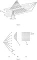
Figure 1 shows schematically an embodiment of the system -
Figure 2 shows a detail of the system, namely radio frequency (rf) traps with eight trapped cold ions overlaid with optical traps, namely optical trapping beams from the optical trapping means -
Figure 3 shows examples of (a) the geometry of a primary structure of an array of cold ions / cold neutral atoms, (b) a secondary (compacted) structure of the cold neutral atoms and (c) a final array of the cold neutral atoms -
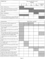
Figure 4 shows a table in which the method according to this invention for the embodiment, shown inFigures 1 and2 , is schematically represented with particular time intervals and when particular devices of the system are active shown as hatched cells of the table -
Figure 5 shows an embodiment of a calibration plate used in the calibration procedure of the embodiment of the system shown inFigures 1 and2 -
Figure 6 shows signals from a photodetector during calibration procedure - The
system 1 for constructing an array of cold neutral atoms according to the present invention comprises the following: - a
vacuum chamber 2, within which ultra-high vacuum can be achieved; -
ion source 3 configured for populating thevacuum chamber 2 withions 6; - radio frequency (rf) trapping means 8, generating
rf trap 9 with a predefined geometry ofrf trapping sites 10, configured for capturing ions in thevacuum chamber 2 into the array with aprimary structure 16 defined by therf trapping sites 10, and/or for keeping the cold ions in place within theprimary structure 16; - optical trapping means 11, generating optical traps 12, configured for double trapping already trapped
cold ions 6 in theprimary structure 16 and/or for holding thecold ions 6 and/or the coldneutral atoms 21 in place within theprimary structure 16, and optionally for enabling movement of each coldneutral atom 21 or a group of coldneutral atoms 21 by moving the corresponding optical traps 12; - cooling means 7 configured for cooling the
ions 6 and/orneutral atoms 21 within thevacuum chamber 2 to sufficiently low temperature, for example by laser cooling, sympathetic cooling and/or rf cooling, in order for thecold ions 6 / coldneutral atoms 21 to be trapped and/or kept in an ordered structure in therf trapping sites 10 and/or in the optical traps 12; - neutralization means 13, comprising a source of electrons configured for creating a controlled flux of electrons, for neutralizing
cold ions 6 that are trapped and held in place in theprimary structure 16 by the optical trapping means 11 and optionally also by the rf trapping means 8. - The
vacuum chamber 2 is designed to achieve an ultra-high vacuum, in order to enable all the processes according to the present invention of assembling the array of cold neutral atoms. Typical value of the pressure inside thevacuum chamber 2 is below 1×10⁻⁹ mbar. Thevacuum chamber 2 has sufficient optical access for the devices of thesystem 1, for example the cooling means 7 and the optical trapping means 11. For example, thevacuum chamber 2 comprises the following ports 15: a low numerical aperture (NA)port 15a for the cooling means 7, which is implemented as laser cooling means, twohigh NA ports port 15f for the neutralization means. - The
ion source 3 emits the positively charged ions (cations) of a particular atom species into thevacuum chamber 2, preferably in a beam ofions 5 towards therf trap 9, in a controlled way. Preferably, all emitted ions have the same electric charge. In one of possible embodiments of thesystem 1, a Strontium (Sr) atom source described in Schioppo2012 [17] in combination with photoionization diode-lasers disclosed in Vant2006 [22] may be used as theion source 3. - Species of atoms that are suitable as building blocks of the array assembly according to the present invention should satisfy the following requirements: in their ionized state they should be suitable to be trapped and held in place by the optical trapping means 11 and by the rf trapping means 8 and suitable to be cooled by laser or other means; and in their neutral state they should be suitable to be trapped and held in place by the optical trapping means 11. For example, alkaline-earth atoms from the second group of periodic system, particularly Strontium (Sr), and alkaline-earth-like atoms, particularly Ytterbium (Yb), are suitable for this purpose, as disclosed in Karpa2019 [9]. Sr and Yb are particularly suitable because the array constructed according to the present invention can be applied for quantum simulator and/or quantum computers as described in Kaufman2021 [10], where optically trapped cold neutral atoms are excited to Rydberg states, as disclosed in Morgado2021 [12] and Henriet2020 [8].
- The cooling means 7 is designed to cool the ions, and/or subsequently the neutral atoms, within the
vacuum chamber 2. The cooling to sufficiently low temperature is required in order to reduce the kinetic energy of theions 6 and/orneutral atoms 21, so that they can be trapped and held in place in ordered structure by the rf trapping means 8 and/or by the optical trapping means 11. In general, theions 6 and/orneutral atoms 21 may be cooled by the cooling means 7 while they are passing through thevacuum chamber 2, once they are trapped by the rf trapping means 8 and/or by the optical trapping means 11, and/or also after they are neutralized and kept within theprimary structure 16 only by the optical trapping means 11. - Once the
ions 6 are trapped into therf trap 9, the cooling is necessary to (further) reduce their kinetic energy in order to form an ordered structure thus defining therf trapping sites 10, and to further reduce their kinetic energy in order to be held within the optical traps 12 before, during and after the neutralization step. - The cooling means 7 can be implemented in various known ways, for example by laser cooling as disclosed in Metcalf [11], sympathetic cooling as disclosed in Tomza2019 [21], or rf cooling as disclosed in Sriarunothai2017 [19].
- The rf trapping means 8 generates the
rf trap 9 with therf trapping sites 10, into which coldfree ions 6 are captured. The geometry of theprimary structure 16 of the array is defined by the geometry of therf trapping sites 10. Theprimary structure 16 may contain one single cold ion/cold neutral atom or more. One possible geometry of theprimary structure 16 known in the state of the art (Paul1990 [13], Berkeland2002 [2]) is a line of a few to a few ten cold ions. In order to enable required optical access to the trappedions 6 and provide a trapping potential depth of a few ten eV, the blade shaped design of the rf trapping means 8 may be applied as disclosed in Hempel2014 [7], Pokorny2014 [14], He2021 [5]. Preferably, the distance between the neighboringrf trapping sites 10 within theprimary structure 16 is in the order of 10 µm, so that the Coulomb repulsion between the cold ions does not destroy theprimary structure 16 in embodiments where, before the neutralization, thecold ions 6 are held in place within theprimary structure 16 only by the optical trapping means 11. - The optical trapping means 11 generates the optical traps 12 within the
vacuum chamber 2 byoptical trapping beams 11f, wherein the optical traps 12 have essentially the same geometry as therf trapping sites 10, namely that of theprimary structure 16. Once theions 6 are trapped into theprimary structure 16 of therf trap 9 and held in place by the rf trapping means 8 in therf trapping sites 10, the trappedcold ions 6 are overlaid by the optical traps 12 of the optical trapping means, so double-trapping of thecold ions 6 is achieved. - The optical trapping means 11 can be implemented, for example, as optical tweezers.
- The
rf trap 9 exerts stronger force on thecold ions 6 to keep them in theprimary structure 16, so the temperature (kinetic energy) of theions 6 can be higher than the temperature of thecold ions 6 and the coldneutral atoms 21 held in place only by the optical trapping means 11 which exerts weaker force on thecold ions 6 and the coldneutral atoms 21 to keep them in the optical traps 12. That is why the neutralization process is initiated only after thecold ions 6 within theprimary structure 16 are sufficiently cooled by the cooling means 7. - The neutralization means 13 comprises a source of
electrons 13a to create a controlled flux of electrons, optionally also focusing electrodes to create aneutralization beam 13b of electrons, directed toward thecold ions 6, which are trapped in theprimary structure 16 by the rf trapping means 8 and/or by the optical trapping means 11, in order to neutralize the cold ions through electron-ion recombination. A skilled person in the art can appropriately adjust operating parameters of the neutralization means 13, such as electron energy, electron monochromaticity, electron flux (current), electron density (beam diameter) and the direction of the flux of electrons, depending on particular embodiments of the system and the method according to the present invention, in order to achieve reliable neutralization of allcold ions 6 within theprimary structure 16 as quickly as possible, thus generatingneutral atoms 21, while preserving the geometrical arrangement of theneutral atoms 21 in theprimary structure 16, and to achieve that the neutralizedatoms 21 are in such quantum state to allow the coldneutral atoms 21 to be held within the optical traps 12 and to prevent theoptical trapping beams 11f to re-ionize them. - The wavelength and intensity of the
optical trapping beams 11f should be selected appropriately so that for practical purposes they do not re-ionize the neutralizedatoms 21 during or after the neutralization. - Once the cold
neutral atoms 21 are kept in place within theprimary structure 16 by the optical trapping means 11, further manipulation of the geometry of the structure is possible, because the optical trapping means 11 enable such spatial movement of each coldneutral atom 21 or a group of individual coldneutral atoms 21 by moving the corresponding optical traps 12. - For example, in one possible application of the array of the cold
neutral atoms 21, namely for quantum computation, in which it is desired that the distances between neighboring coldneutral atoms 21 are in range of µm, the geometry of theprimary structure 16 can be changed into asecondary structure 17, where the distance between neighboring coldneutral atoms 21 is significantly reduced, so, for example, that the coldneutral atoms 21 can be entangled via Rydberg interactions. Furthermore, given that the neighboringcold ions 6 in the primary structure 16 (in the rf trapping sites 10) held in place by therf trap 9, are not necessarily at equal distances, and consequently neither are the neighboringneutral atoms 21 in theprimary structure 16, thesecondary structure 17 can also be used to structure the coldneutral atoms 21 equidistantly. - Furthermore, the array of cold
neutral atoms 21 in theprimary structure 16 or thesecondary structure 17, which typically is a line (i.e. one-dimensional structure), can be combined into more complexfinal array 18, so for example to form longer one-dimensional structures, arbitrarily shaped two-dimensional structures or even three dimensional structures to be used in different applications. Additional optical traps for thefinal array 18 can either be formed by the optical trapping means 11 or by additional optical trapping means (not shown in Figures). - Optionally, the
system 1 comprises also a high-resolution camera 14 in combination with a high numerical aperture (NA)optics 11e, with NA sufficiently high configured for imaging individualcold ions 6 in therf trapping sites 10 and/or in the optical traps 12 and/or individual coldneutral atoms 21 in the optical traps 12. The high-resolution camera 14 is directed toward a trapping area, where therf trapping sites 10 and the optical traps 12 are located, and possibly also toward a construction area, where, in some embodiments, thefinal array 18 of coldneutral atoms 21 is constructed, in order to monitor whether and to what extent theprimary structure 16,secondary structure 17 and/or thefinal array 18 are filled with thecold ions 6 or coldneutral atoms 21. This is especially important in development phase of a particular embodiment of thesystem 1 and in calibration phase, where parameters of thesystem 1 are adjusted to achieve the required performance. - The
system 1 comprises also an electronic control system (not shown in Figures) with processing, memory and connectivity capabilities, which is connected to the above-described devices of the system and on which the appropriate software modules can be run in order to carry out methods described below, in order to operate, monitor and control thesystem 1. - The method of constructing an array of cold
neutral atoms 21 with the geometry of theprimary structure 16, held in place by the optical traps 12, according to the present invention comprises the following steps: - Step 1: controlled release of ions into the
vacuum chamber 2, preferably in abeam 5 of ions directed toward therf trapping sites 10. - Step 2: trapping the
ions 6 into therf trap 9, and holding thecold ions 6 in place in therf trapping sites 10, which define theprimary structure 16 of thecold ions 6. - Step 3: overlaying the
cold ions 6, which are already held in place in therf trapping sites 10 within theprimary structure 16, with the optical traps 12, thereby double-trapping thecold ions 6, and holding them in place by the optical traps 12. - Step 4: neutralizing the
cold ions 6 within theprimary structure 16 through electron-ion recombination, and thus generating the coldneutral atoms 21 within theprimary structure 16. - In addition to the above mentioned four steps, a cooling step is necessary for cooling the ions/neutral atoms in order to reduce their kinetic energy (temperature), namely for the
ions 6 to be trapped, achieve a stable structure and kept in place in theprimary structure 16 by therf trap 9, and for thecold ions 6 and the coldneutral atoms 21 to be kept in place within the optical traps 12. The cooling step can be continuous or comprise intervals of cooling, and can run simultaneously with the above mentioned four steps and/or can run between or after each of these steps. The starting point and duration of the cooling step or its intervals depend on parameters of a particular embodiment of thesystem 1, such as the kinetic energy of the ions/neutral atoms and the depth of therf trap 9 and the optical traps 12. - For example, in certain embodiments the
ions 6, when released from theion source 3, have sufficiently low kinetic energy (temperature) and therf trap 9 is designed to have sufficient depth, i.e. to exert sufficient electric force, to capture theions 6 floating in thevacuum chamber 2 without any cooling. However, theions 6 should always be cooled to achieve their ordered structure within therf trap 9. Given that in general the optical traps 12 have significantly lower depth than therf trap 9 and are not able to hold in placeuncooled ions 6 /neutral atoms 21, the cooling step should always be initiated before the neutralization step is concluded, namely before theneutral atoms 21 are kept in place merely by the optical traps 12, so that once theneutral atoms 21 are to be kept in place merely by the optical traps 12, they have sufficiently low kinetic energy. - The above-described method, after completion of
step 4 and the cooling step, yields an array of coldneutral atoms 21 held in place by the optical traps 12 in a predefined geometry, namely that of theprimary structure 16, an example of which is shown inFigure 3a . -
Step 1 is achieved by theion source 3,step 2 is achieved by the rf trapping means 8,step 3 is achieved by the optical trapping means 11,step 4 is achieved by the neutralization means 13, and the cooling step is caried out by the cooling means 7. -
Step 3 can be achieved by switching on the optical trapping means 11 only afterstep 2 and the cooling step are completed, or can be achieved with the same result also if the optical trapping means 11 are switched on earlier, for example already duringstep - Preferably,
step 2 is ended by switching off the rf trapping means 8, immediately before initiatingstep 4 because the rf trapping means 8, if switched on, may interfere with theneutralization beam 13b of electrons from the neutralization means 13, and therefore interfere with the neutralization of thecold ions 6. - Optionally, additional steps are possible after
step 4 and the cooling step to achieve various arrays that are more suitable for particular applications. For example, an additional step to reshape theprimary structure 16 into a more compactsecondary structure 17 by moving the corresponding optical traps 12, namely to achieve the reduction of the distances between neighboring coldneutral atoms 21 within thesecondary structure 17, and example of which is shown inFigure 3b . - Further additional steps are possible after
step 4 and the cooling step, or after above mentioned additional steps, to construct more complexfinal arrays 18 of coldneutral atoms 21 by combining the arrays in the shape of theprimary structure 16 or thesecondary structure 17. The steps of constructing thefinal array 18 includes moving the coldneutral atoms 21 in the primary structure or in the secondary structure from the trapping area into the construction area, both within thevacuum chamber 2. In the construction area the coldneutral atoms 21 are held in place by the additional optical traps produced by the optical trapping means 11 or by additional optical trapping means (not shown in Figures). In order to reduce time of the construction of thefinal array 18, the additional steps of moving theprimary structure 16 orsecondary structure 17 from the trapping area to the construction area may run simultaneously with the next iteration of the above-mentioned method, namely steps 1 to 4 and the cooling step. - During or after
step 2 a verification step can be added, carried out by imaging thecold ions 6 in therf trapping sites 10 and/or in the optical traps 12 by the high-resolution camera 14, to check whether and to what extent therf trapping sites 10 and/or the optical traps 12 are filled with thecold ions 6. - During or after
step 3 an additional verification step can be added, carried out by imaging the coldneutral atoms 21 in the optical traps 12 by the high-resolution camera 14, to check whether and to what extent the optical traps 12 are filled with the coldneutral atoms 21. The imaging of thecold ions 6 and/or coldneutral atoms 21 in therf trapping sites 10 and/or in the optical traps 12 can be used also in calibration procedures. - The inventive method is not limited to carrying out the individual method steps in a sequential manner or as shown in the preferred embodiment of
Figure 4 . Rather, the inventive method encompasses carrying out two or more essential and/or optional method steps in parallel or at least partially overlapping in time. For example, the cooling step can be employed at all times, for example in parallel or partially overlapping with any of the essential and/or optional method steps. - The inventive method is not limited by time durations of individual steps, e.g. by those exemplified in
Figure 4 . Rather, the inventive method encompasses carrying out the individual steps in time intervals of any duration being suited to the actual circumstances. In most applications of the method, it is preferable, that these steps are carried out in as short time intervals as practically achievable, which is particularly advantageous, for example, for use in quantum computing. - An embodiment of the
system 1 according to the present invention shown inFigure 1 and2 produces the array of the coldneutral atoms 21 with geometry of theprimary structure 16 with eight coldneutral atoms 21 positioned in a line. Theprimary structure 16 is shown also inFigure 3a . - In this embodiment the
vacuum chamber 2 is implemented as a cylindrical stainless-steel chamber 2a with base pressure less than 1×10⁻⁹ mbar in combination with a vacuum pumping system comprising anion pump 2b and a titanium sublimation pump 2c, and vacuum gauges 2d. - The
ion source 3 is implemented as a combination of a Strontium (Sr) oven 3a, with amechanical shutter 3b, placed inside thevacuum chamber 2, and aphotoionization laser system 3c generating two photoionization laser beams of wavelengths of 461 nm and 405 nm, respectively, for two-photon ionization of hot Sr atoms. Thephotoionization laser beams 3d are directed to intersect the path of abeam 4 of hot Sr atoms from the outlet of the Sr oven 3a to therf trapping sites 10. After ionization thebeam 5 of Sr+ ions proceeds toward the rf trapping sites, where some of the Sr+ ions are trapped therein. The Sr oven 3a comprises a resistive heated filament and a Sr dendrite of 5N purity in a stainless-steel housing, and has an integrated collimation tube of 1 mm diameter and 5 mm in length which collimates thebeam 4 of hot Sr atoms with temperature of over 450° C, which is directed toward therf trapping sites 10. Themechanical shutter 3b with on/off function is used to control thebeam rf trap 9. - The rf trapping means 8 is implemented as a linear quadrupole trapping system 8 comprising four
longitudinal rod electrodes 8a and two on-end electrodes (not shown inFigure 1 and2 ). The rf trapping means 8 is designed to generate arf trap 9 with eightrf trapping sites 10 for eightSr+ ions 6 in a linearprimary structure 16 along itscentral axis 8c. Therf trap 9 has a minimum trap depth well above the mean kinetic energy of ions in theSr+ ion beam 5, namely of the order of 10 eV. The design of the linear quadrupole trapping system 8 allows high optical access to the rf trapping sites for thebeam 5 of Sr+ ions from theion source 3, for the cooling means 7, for the optical trapping means 11, for the high-resolution camera 14, and for aneutralization beam 13b of electrons from the neutralization means 13. - The cooling means 7 is implemented as four laser cooling systems, namely a
laser cooling system 7a generating cooling beam of wavelength of 422 nm, a repumper laser system 7b generating 1092 nm repumper beam, a sideband cooling laser system 7c generating 674 nm sideband cooling beam, and a quencher laser system 7d generating 1033 nm quencher beam. All these beams are directed toward therf trapping sites 10, namely toward thecentral axis 8c of the rf trapping means 8. The first twolaser cooling systems 7a, 7b are used to cool the trappedions 6 close to Doppler limit of about 0.48 mK. The second two laser cooling systems 7c, 7d are used for cooling the trappedions 6 close to final sub-Doppler temperature limit of about 0.2 µK. This temperature allows thecold ions 6 to form ordered linear chain in therf trapping sites 10 and to be held in place by the optical trapping means 11, and also allows, after neutralization, the coldneutral atoms 21 to be held in place by the optical trapping means 11 for extended periods of time (>1 min). - The neutralization means 13 is implemented as a source of
low energy electrons 13a capable of generating various electron beams with electron monochromaticity < 0.5 eV, electron energies between 0.1 eV and 100 eV, and beam current (flux) between 1 nA and 1 mA, which allows the selection of appropriate operating parameters for theneutralization beam 13b of electrons. The operating parameters of the neutralization means 13, which should be adjusted to this particular embodiment of the system, are electron energy, electron flux (current), electron density (beam diameter) and the direction of theneutralization beam 13b of electrons in order to achieve reliable neutralization of allcold ions 6 within theprimary structure 16 as quickly as possible, while preserving the geometrical arrangement of the coldneutral atoms 21 in theprimary structure 16, and to achieve that the neutralizedatoms 21 are in the quantum state to be held within the optical traps 12 and that theoptical trapping beams 11f do not re-ionize them. - The optical trapping means 11 in this embodiment comprises a
laser tweezer system 11a, generating theoptical trapping beams 11f with wavelength of 515-nm, adichroic mirror 11d and a high numerical aperture (NA)optics 11e with NA > 0.5. Thelaser tweezer system 11a comprises two crossed acousto-optic deflectors (AOD) 11b andmotorized lens 11c. The AODs 11b split an initial laser beam into eight separateoptical trapping beams 11f and are also used to steer theoptical trapping beams 11f independently from one another, which consequently enable the optical traps 12 to be independently steered within thevacuum chamber 2. EachAOD 11b is used to steer theoptical trapping beams 11f independently from one another along one axis (x or y axis), so two crossedAODs 11d enable the steering of theoptical trapping beam 11f in an xy target plane. Themotorized lens 11c is used to focus theoptical trapping beams 11f at a certain distance from the optical trapping means 11 (i.e. along z axis), thereby defining the distance of the xy target plane from the optical trapping means 11. Thehigh NA optics 11e with NA > 0.5 is used within the context of the optical trapping means 11 to focus theoptical trapping beams 11f thereby defining the diameter of the optical traps 12. Theoptical trapping beams 11f are directed toward therf trap 9 in thevacuum chamber 2. The steering of the optical traps 12 is necessary to achieve their spatial overlaying with therf trapping sites 10 and possibly to move the optical traps 12 with coldneutral atoms 21 to create more compact structure, namely thesecondary structure 17, or to move theprimary structure 16 or thesecondary structure 17 from the trapping area to the construction area to construct thefinal array 18 as mentioned above. To accomplish that therf trapping sites 10 are spatially overlaid by the optical traps 12 in this embodiment of thesystem 1, a calibration procedure is necessary, and is described below. - The
dichroic mirror 11d is used to allow thehigh NA optics 11e to be used for two purposes: to focus theoptical trapping beams 11f, as mentioned above, and for imaging thecold ions 6 and/or coldneutral atoms 21 in therf trapping sites 10 / optical traps 12 with the high-resolution camera 14 through the sameoptical port 15c in thevacuum chamber 2 wall as is used to introduce theoptical trapping beams 11f into thevacuum chamber 2. Thedichroic mirror 11d reflects theoptical trapping beams 11f with wavelength of 515 nm from thelaser tweezer system 11a towards thehigh NA optics 11e and accompanyingoptical port 15c through which theoptical trapping beams 11f enter thevacuum chamber 2. On the other hand, thedichroic mirror 11d transmits the light with the wavelengths of 422 nm for imaging thecold ions 6, and/or the light with the wavelengths of 461 nm and/or 689 nm for imaging coldneutral atoms 21, coming from thecold ions 6 / coldneutral atoms 21 in therf trapping sites 10 and/or the optical traps 12 within thevacuum chamber 2 to the high-resolution camera 14. - This embodiment of the
system 1 comprises the high-resolution camera 14 which is implemented as an electron-multiplied charge-coupled-device (EMCCD)camera 14 with the resolution of more than 1 Mpixel and high (single photon) sensitivity in combination with thehigh NA optics 11e. TheEMCCD camera 14 is used to monitor whether therf trapping sites 10 are filled with thecold ions 6 and whether the optical traps 12 are filled with thecold ions 6 or the coldneutral atoms 21. To image thecold ions 6 in therf trapping sites 10 and/or in the optical traps 12, fluorescence imaging is applied by using the cooling beam at 422 nm and the repumper beam at 1092 nm. To image the coldneutral atoms 21 in the optical traps 12, fluorescence imaging is applied by using the photoionization laser beam at 461 nm and/or additional beams at 689 nm and/or 679 nm and/or 707 nm from additional beam sources not shown inFigure 1 . A particular choice of the laser beams required for imaging the cold neutral atoms depends on the required fidelity and survival probability of the atom imaging. - For example, in a possible calibration process, the high-
resolution camera 14 can be used to determine a time period in which therf trapping sites 10 are entirely filled with thecold ions 6, namely by monitoring therf trapping sites 10. The high-resolution camera 14 can also be used to determine time periods necessary for cooling theions 6 or theneutral atoms 21. The temperature of theions 6 /neutral atoms 21 in the traps can be measured with the high-resolution camera 14 indirectly, for example by switching off therf trap 9 or the optical traps 12 and measuring the time evolution of ion/atom position. In the calibration process described below, the high-resolution camera 14 is used to determine the position of the optical traps 12 relative to therf trapping sites 10, in order to adjust the position of the optical traps 12 to spatially overlay them with therf trapping sites 10, including capturing the image of acalibration mask 20 used in the calibration process. - In this embodiment, the
system 1 according to the present invention comprises aphotodetector 19 which is used in the calibration process for calibrating the position of the optical traps 12, which is described below. Thephotodetector 19, can be implemented, for example, as aphotodiode 19. Thephotodetector 19 is positioned on itsoptical port 15d on the same optical axis as theEMCCD camera 14 and theoptical trapping beams 11f once they enter thevacuum chamber 2, but on the other side of thevacuum chamber 2 relative to theoptical port 15c for the optical trapping means 11 as shown inFigure 1 . Theoptical port 15d is also necessary for functioning of the optical trapping means 11. - In this embodiment, the
vacuum chamber 2 has oneoptical port 15a for the laser cooling means, oneoptical port 15b forphotoionization system 3c, oneoptical port 15c for the high-resolution camera and the optical trapping means, oneoptical port 15d for thephotodetector 19, oneport 15e for an electrical high-voltage radio-frequency feedthrough for the rf trapping means 8 and for the Sr oven 3a, oneport 15f for the neutralization means 13, and aport 15g for thevacuum pumping system 2b and the vacuum gauges 2d. - The method according to the present invention as implemented in the embodiment shown in
Figures 1 and2 is schematically shown in a table inFigure 4 . - Columns to the right in the chart represent time intervals A, B, C, D and E, wherein interval A lasts 10 s,
interval B 10 ms,interval C 10 ms, interval D is in the range of 1 to 10 ms, and optional interval E lasts 50 ms. The upper rows of the chart show during which time intervals A - E particular steps of the method according to the present invention, namely steps 1 - 4, the cooling step and the optional verification step, are carried out, which is shown as hatched cells in the table. The below rows of the chart show during which time intervals A - E particular devices of thesystem 1 are active, which is shown as hatched cells in the table. - For example,
step 1, in which theions 6 are released into thevacuum chamber 2 toward therf trapping sites 10, is accomplished in interval A. To achieve that, during interval A the Sr oven 3a, emitting the Sr atoms, is switched on, themechanical shutter 3b of the Sr oven 3a is open, and thephotoionization laser system 3c, generating both photoionization laser beams, namely ofwavelengths 461 nm and 405 nm, is active. For practical reasons, the Sr oven 3a is switched on during all intervals, and the flux of the Sr atoms is controlled by themechanical shutter 3b. -
Step 2, namely trapping and holding theions 6 in therf trapping sites 10, is carried out during intervals A, B and C. There is a short delay between releasing theions 6 into thevacuum chamber 2 and trappingfirst ions 6 into therf trap 9, which is not shown in the chart inFigure 4 due to relatively short duration and stochasticity of the delay. To accomplishstep 3, the rf trapping means is switched on during intervals A, B and C. -
Step 3, double-trapping and holding thecold ions 6 by the optical traps 12, and then holding the coldneutral atoms 21 by the optical traps 12, is carried out during intervals C, D and E. That is why the optical trapping means 11 is switched on during these three intervals. The optical trapping means 11 could be switched on during intervals A and B as well, because it would not interfere with other steps of the method. -
Step 4, neutralization of the capturedcold ions 6, is achieved during interval D, so the neutralization means 13 is active during this interval. Duringstep 4, thecold ions 6, until they are neutralized, and then the coldneutral atoms 21, are held in place merely by the optical traps 12, because therf trap 9 is no longer active. The rf trapping means 8 is switched off before initiation ofstep 4, because the electric field of the rf trapping means 8 can interfere with theneutralization beam 13b of electrons from the neutralization means 13. - The cooling step is carried out during intervals A and B by the cooling means 7. The
ions 6 in therf trap 9 are first cooled with the 422 nm cooling beam and 1092 nm repumper beam close to Doppler temperature limit of about 0.48 mK during interval A, and then with the 674 nm sub-doppler cooling beam and the 1033 nm quencher beam close to sub-Doppler temperature limit of approx. 0.2 µK during interval B. - In the chart in
Figure 4 , the optional verification step is shown, which is carried out during interval E, to verify whether theprimary structure 16 comprising the coldneutral atoms 21, held in place by the optical traps 12, is defect free. During this interval, the high-resolution camera 14 captures the image of the coldneutral atoms 21 in the optical traps 12 by applying fluorescence imaging using the photoionization laser beam at 461 nm and/or additional beams at 689 nm and/or 679 nm and/or 707 nm, so in this interval the high-resolution camera 14 is active and so is thephotoionization laser system 3c, but generating only the photoionization laser beam with the wavelength of 461 nm, and also the additional beam sources (not shown inFigure 1 ). - The main purpose of the calibration procedure in this embodiment, according to the calibration method described below, is to spatially adjust the position of the optical traps 12, which is done by moving the
optical trapping beams 11f and focusing them at various distances from the optical trapping means 11, or more precisely at various distances from thehigh NA optics 11e, in order to spatially lay the optical traps 12 exactly over therf trapping sites 10. - In
calibration step 1, theions 6 are captured in therf trap 9, sufficiently cooled by the cooling means 7, and held in place by the rf trapping means 8 in an ordered structure, namely in theprimary structure 16, defined by therf trapping sites 10; for example by carrying outsteps rf trapping sites 10 are defined by the location of thecold ions 6 in therf trap 9. - In
calibration step 2, the fluorescent imaging by the high-resolution camera 14 is applied in order to determine the exact position of thecold ions 6, and thereby the exact position of therf trapping sites 10, thereby defining an xy plane of the internal coordinate system of the high-resolution camera 14. To image thecold ions 6, the focus of the high-resolution camera 14 is set on thecold ions 6. The imaging is done in this embodiment by using the cooling beam at 422 nm and the repumper beam at 1092 nm. - In
calibration step 3, thecalibration mask 20, shown inFigure 5 , is inserted into the rf trapping means 8 along itscentral axis 8c, so that thecentral axis 8c lies on the flat surface of thecalibration mask 20 and so that the flat surface of thecalibration mask 20 is perpendicular to the optical axis of theoptical trapping beams 11f coming from thehigh NA optics 11e to therf trap 9. Optionally, to place thecalibration mask 20 into the exact position, thecalibration mask 20 is moved until its image as captured by the high-resolution camera 14 is in focus. - The
calibration mask 20 is essentially athin plate 20a, for example made of glass and thereby transparent, covered by a thin untransparent metal film, withoptical holes 20b with known geometry, for example the diameter of about 3 µm, placed equidistantly in a line with a distance of 10µm between the neighboringoptical holes 20b. Theoptical holes 20b may be implemented as actual holes in theplate 20a, or in case the plate is transparent and covered by an untransparent film, by absence of the film where theoptical holes 20b should be. In this embodiment thecalibration mask 20 has fiveoptical holes 20b. - In
calibration step 4, the high-resolution camera 14 captures the image of thecalibration mask 20, particularly the position of theoptical holes 20b in thecalibration mask 20, whereas the surface of thecalibration plate 20a is aligned with a correct target plane in which lies the central axis, and whereas the correct target plane is also perpendicular to the optical axis of theoptical trapping beams 11f coming from thehigh NA optics 11e to therf trap 9. The light for capturing this image can come from a separate source of light or from surrounding light from outside thevacuum chamber 2 that is introduced through an optical port (not shown in Figures). From the image of theoptical holes 20b in the correct target plane, the coordinates of theoptical holes 20b in the xy plane according to an internal coordinate system of the high-resolution camera 14 are obtained. - In
calibration step 5, the xy target plane of an internal coordinate system of the optical trapping means 11 is calibrated with the xy plane of the internal coordinate system of the high-resolution camera 14 and the focus of theoptical trapping beam 11f, expressed as z axis in the internal coordinate system of the optical trapping means 11, is calibrated at the exact distance, where thecalibration mask 20 and also the correct target plane are positioned. - The
optical trapping beam 11f is systematically steered according to its internal coordinate system across the xy target plane, thereby across thecalibration mask 20. The steering of theoptical trapping beam 11f in the xy target plane is achieved by theAODs 11b. On the other side of thecalibration mask 20, the amount of the light from theoptical trapping beam 11f coming through theoptical holes 20b of thecalibration mask 20 is captured by thephotodetector 19. Various photodetector signals are shown inFigure 6 . The strength of the photodetector signal depends on the position of theoptical trapping beam 11f relative to the position of theoptical holes 20b of thecalibration mask 20, namely when theoptical trapping beam 11f shines directly through theoptical hole 20b in thecalibration mask 20, the photodetector signal is the strongest. - Therefore, the peaks of the photodetector signal indicate the position of the
optical holes 20b, which was incalibration step 4 expressed in the xy plane of the internal coordinate system of thehigh resolution camera 14, now expressed in the xy target plane of the internal coordinate system of the optical trapping means 11, by comparing the strength of the photodetector signal with the position of theoptical trapping beam 11f, expressed in the xy target plane. - The shape of the photodetector signal indicates also to what extent the optical trapping beam is focused at the exact distance where the
calibration mask 20 and also the correct target plane are positioned. The first photodetector signal (a) inFigure 6 shows that the signal relatively slowly reaches its peak and then descends, because the focus of theoptical trapping beam 11f is not yet aligned with the correct target plane. The second photodetector signal (b) inFigure 6 reaches its peak and descends from it more steeply, thereby indicating that the focus of theoptical trapping beam 11f is closer to the correct target plane. And the third photodetector signal (c) inFigure 6 has the steepest shape of rising and falling of the signal, thereby indicating that in this scanning the focus of theoptical trapping beam 11f is at the same distance, expressed as z coordinate of the internal coordinate system of the optical trapping means 11, as the correct target plane. - The xy target plane, thereby the
calibration mask 20, is systematically scanned by theoptical trapping beam 11f; however, several scannings of the entire xy target plane is done, whereas each scanning has a different focus of theoptical trapping beam 11f, i.e. with a focus at a different distance from the optical trapping means 11. Themotorized lens 11c, which operates according to the internal coordinate system of the optical trapping means 11, is used to achieve different focuses of theoptical trapping beam 11f. The photodetector signal is observed while the entire target plane is scanned several times by theoptical trapping beam 11f, and compared with the position of theoptical trapping beam 11f, expressed in xyz coordinates of the internal coordinate system of the optical trapping means 11. - At the end of
calibration step 5, thecalibration mask 20 is removed from the rf trapping means 8. - In
calibration step 6, the exact position of theoptical trapping beams 11f, in order to lay the optical traps 12 over therf trapping sites 10, is determined by transforming the position of thecold ions 6 obtained incalibration step 2, which is expressed in the xy plane of the internal coordinate system of thehigh resolution camera 14, into the position of theoptical trapping beams 11f, which is expressed in the xy target plane, and focusing theoptical trapping beams 11f at the same distance, expressed as z coordinate of the internal coordinate system of the optical trapping means 11, as the correct target plane, which was obtained incalibration step 5. - Therefore, the
system 1 is calibrated to be used according the above-described method, namely the optical traps 12 can be spatially laid precisely over therf trapping sites 10. -
- [1] Akerman, N., Glickman, Y., Kotler, S., Keselman, A., & Ozeri, R. (2011, November). Quantum control of 88Sr+ in a miniature linear Paul trap. Applied Physics B, 107, 1167-1174. doi:10.1007/s00340-011-4807-6
- [2] Berkeland, D. J. (2002, August). Linear Paul trap for strontium ions. Review of Scientific Instruments, 73, 2856-2860. doi:10.1063/1.1489073
- [3] Brownnutt, M. (2007, September). 88Sr+ ion trapping techniques and technologies for QIP. Ph.D. dissertation, Imperial College London. https://www.imperial.ac.uk/media/imperial-college/research-centres-and-groups/ion-trapping/public/Brownnutt-PhD-Thesis-2009.pdf
- [4] Dubost, B. (2012). Light-matter interaction with atomic ensembles. Ph.D. dissertation, Université Paris-Diderot - Paris VII; Universitat Politécnica de Catalunya. https://tel.archives-ouvertes.fr/tel-00818499/file/these.pdf
- [5] He, R., Cui, J.-M., Li, R.-R., Qian, Z.-H., Chen, Y., Ai, M.-Z., Huang, Y.-F., Li, C.-F., Guo, G.-C. (2021, July). An ion trap apparatus with high optical access in multiple directions. Review of Scientific Instruments, 92, 073201. doi:10.1063/5.0043985
- [6] Heazlewood, B. R. (2019, January). Cold ion chemistry within Coulomb crystals. Molecular Physics, 117, 1934-1941. doi:10.1080/00268976.2018.1564850
- [7] Hempel, C. (2014). Digital quantum simulation, Schrödinger cat state spectroscopy and setting up a linear ion trap. Ph.D. dissertation, University of Innsbruck (Austria). https://quantumoptics.at/images/publications/dissertation/hempel_diss.pdf
- [8] Henriet, L., Beguin, L., Signoles, A., Lahaye, T., Browaeys, A., Reymond, G.-O., & Jurczak, C. (2020, September). Quantum computing with neutral atoms. Quantum, 4, 327. doi:10.22331/q-2020-09-21-327
- [9] Karpa, L. (2019). Trapping Single Ions and Coulomb Crystals with Light Fields. Springer International Publishing. doi:10.1007/978-3-030-27716-1
- [10] Kaufman, A. M., & Ni, K.-K. (2021, November). Quantum science with optical tweezer arrays of ultracold atoms and molecules. Nature Physics, 17, 1324-1333. doi:10.1038/s41567-021-01357-2
- [11] Metcalf, H. J., Straten, P. (1999), Laser cooling and trapping. Springer International Publishing. doi:10.1007/978-1-4612-1470-0
- [12]Morgado, M., & Whitlock, S. (2021, June). Quantum simulation and computing with Rydberg-interacting qubits. AVS Quantum Science, 3, 023501. doi:10.1116/5.0036562
- [13] Paul, W. (1990, July). Electromagnetic traps for charged and neutral particles. Reviews of Modern Physics, 62, 531-540. doi:10.1103/revmodphys.62.531
- [14]Pokorny, F. (2014, March). Experimental setup for trapping strontium Rydberg ions. Master's thesis, Leopold-Franzens University of Innsbruck. https://www.quantumoptics.at/images/publications/diploma/master_pokorny.pdf
- [15] Poschl, A. (2018). Laser Ablation Loading and Single Ion Addressing of Strontium in a Linear Paul Trap. Ph.D. dissertation, KTH, School of Engineering Sciences (SCI). https://kth.diva-portal.org/smash/get/diva2:1203307/FULLTEXT01.pdf
- [16]Schäfer, F., Fukuhara, T., Sugawa, S., Takasu, Y., Takahashi, Y. (2020, July). Tools for quantum simulation with ultracold atoms in optical lattices. Nature Reviews Physics, 2, 411-425. https://doi.org/10.1038/s42254-020-0195-3
- [17]Schioppo, M., Poli, N., Prevedelli, M., Falke, S., Lisdat, C., Sterr, U., & Tino, G. M. (2012, October). A compact and efficient strontium oven for laser-cooling experiments. Review of Scientific Instruments, 83, 103101. doi:10.1063/1.4756936
- [18]Schlosser, N., Reymond, G., Protsenko, I., & Grangier, P. (2001, June). Sub-poissonian loading of single atoms in a microscopic dipole trap. Nature, 411, 1024-1027. doi:10.1038/35082512
- [19]Sriarunothai, T., Giri, G.-S., Woelk., S., Wunderlich, C. (2017, November). Radio frequency sideband cooling and sympathetic cooling of trapped ions in a static magnetic field gradient. Journal of Modern Optics, 65, 560-567. doi:10.1080/09500340.2017.1401137
- [20] Thompson, R. C. (2015, January). Ion Coulomb crystals. Contemporary Physics, 56, 1-17. doi:10.1080/00107514.2014.989715
- [21]Tomza, M., Jachymski, K., Gerritsma, R., Negretti, A., Calarco, T., Idziaszek, Z., Julienne, P.-S., Cold hybrid ion-atom systems. Reviews of Modern Physics, 91, 035001. doi:10.1103/RevModPhys.91.035001
- [22]Vant, K., Chiaverini, J., Lybarger, W., & Berkeland, D. J. (2006, July). Photoionization of strontium for trapped-ion quantum information processing. https://doi.org/10.48550/arxiv.quant-ph/0607055
Claims (16)
- System (1) for constructing an array of cold neutral atoms (21) characterized in that it comprises:- a vacuum chamber (2), within which ultra-high vacuum can be achieved;- an ion source (3) configured for populating the vacuum chamber (2) with positively charged ions (6);- a radio frequency (rf) trapping means (8), generating a rf trap 9 with a predefined geometry of rf trapping sites (10), configured for capturing free ions into the rf trap 9 and for keeping the cold ions (6) in place within the array with a primary structure (16), defined by the rf trapping sites (10);- an optical trapping means (11), generating optical traps (12), configured for double trapping already trapped cold ions (6) in the primary structure (16) and for holding the cold ions (6) and/or the cold neutral atoms (21) in place within the primary structure (16);- a cooling means (7) configured for cooling the ions (6) and/or neutral atoms (21) within the vacuum chamber (2) to sufficiently low temperature, in order for the cold ions (6) and/or cold neutral atoms (21) to be trapped and/or kept in an ordered structure in the rf trapping sites (10) and/or in the optical traps (12);- a neutralization means (13), comprising a source of electrons (13a) configured for creating a controlled flux of electrons, for neutralizing the cold ions (6) that are trapped and held in place in the primary structure (16) by the optical trapping means (11) and/or by the rf trapping means (8).
- The system (1) according to claim 1, wherein species of atoms for ions (6) and neutral cold atoms (21) is selected either from alkaline-earth atoms from the second group of periodic system, preferably Strontium (Sr), or alkaline-earth-like atoms, preferably Ytterbium (Yb).
- The system (1) according to claims 1 through 2, wherein the cooling means (7) is implemented by laser cooling.
- The system (1) according to claims 1 through 3, wherein the optical trapping means (11) comprise a laser tweezer system (11a).
- The system (1) according to claims 1 through 4, wherein the optical trapping means (11) is additionally configured for moving each cold neutral atom (21) and/or a group of cold neutral atoms (21) in the primary structure (16) by moving the corresponding optical traps (12) in order to construct an array of cold neutral atoms with a secondary structure (17) and/or a final array (18).
- The system (1) according to claims 1 through 5, wherein the system (1) comprises a high-resolution camera (14) configured for imaging the cold ions (6) and/or imaging cold neutral atoms (21).
- The system (1) according to claims 4 through 6, wherein the optical trapping means comprises a dichroic mirror (11d).
- The system (1) according to claims 1 through 7, wherein the system (1) comprises a photodetector (19).
- Method of constructing an array of cold neutral atoms (21) with the geometry of a primary structure (16), held in place by optical traps (12) characterized in that the method comprises the following steps:- step 1: controlled release of ions (6) into a vacuum chamber (2), preferably in a beam (5) of ions directed toward rf trapping sites (10);- step 2: trapping the ions (6) into an rf trap (9), and holding the cold ions (6) in place in the rf trapping sites (10);- step 3: overlaying the cold ions (6), which are already held in place in the rf trapping sites (10), with the optical traps (12), thereby double-trapping the cold ions (6), and holding the cold ions (6) in place by the optical traps (12);- step 4: neutralizing the cold ions (6) within the primary structure (16) and thus generating the cold neutral atoms (21) within the primary structure (16);wherein the method comprises also a cooling step for cooling the ions (6) and/or neutral atoms (21) in order to reduce their kinetic energy (temperature), for the ions (6) to be trapped, achieve a stable structure and to be kept in place in the primary structure (16) by the rf trap (9), and for the cold ions (6) and the cold neutral atoms (21) to be kept in place within the optical traps (12); wherein the cooling step can be continuous or comprise intervals of cooling, and can run simultaneously with the above mentioned four steps and/or can run between or after each of these steps.
- The method according to claim 9, wherein step 3 is achieved by the optical traps (12) being switched on already during step 1 and/or 2.
- The method according to claim 9 through 10, wherein the rf trap (9) is switched off immediately before initiating step 4.
- The method according to claim 9 through 11, wherein after steps 1 through 4 and the colling step additional steps are added for reshaping the primary structure (16) of the cold neutral atoms (21) into a secondary structure (17) and/or into a final array (18) by moving the corresponding optical traps (12).
- The method according to claim 9 through 12, wherein during or after step 2 a verification step is added by imaging the cold ions (6) in the rf trapping sites (10) and/or in the optical traps (12), and/or an additional verification step is added by imaging the cold neutral atoms (21) in the optical traps (12).
- The method according to claim 9 through 13, wherein the cooling step is carried out in two intervals: in interval A the ions (6) are cooled close to Doppler temperature limit of about 0.48 mK and in interval B the ions (6) are cooled close to sub-Doppler temperature limit of about 0.2 µK.
- Calibration method for calibrating the system (1) to adjust the position of the optical traps (12) in order to spatially lay them exactly over the rf trapping sites (10) characterized in that the calibration method comprises the following steps:- calibration step 1: capturing the ions (6) in the rf trap (9), cooling them sufficiently, so that they are held in place by the rf trapping means (8) in an ordered structure, namely in the primary structure (16), defined by the rf trapping sites (10);- calibration step 2: imaging of the cold ions (6) by the high-resolution camera (14) is applied in order to determine the exact position of the cold ions (6), thereby defining the exact position of the rf trapping sites (10) in an xy plane of an internal coordinate system of the high-resolution camera (14);- calibration step 3: inserting a calibration mask (20) into the rf trapping means (8) along its central axis (8c), so that the central axis (8c) lies on the flat surface of the calibration mask (20) and so that the flat surface of the calibration mask (20) is perpendicular to the optical axis of the optical trapping beams (11f) coming from the high NA optics (11e) to the rf trap (9);- calibration step 4: capturing the image of the calibration mask (20), particularly the position of the optical holes (20b) in the calibration mask (20), thereby obtaining the coordinates of the optical holes (20b) in the xy plane of the internal coordinate system of the high-resolution camera 14;- calibration step 5: calibrating an xy target plane of an internal coordinate system of the optical trapping means (11) with the xy plane of the internal coordinate system of the high-resolution camera (14), and calibrating the focus of the optical trapping beam (11f), expressed as z axis in the internal coordinate system of the optical trapping means (11), at the exact distance, where the calibration mask (20) and also the correct target plane are positioned; by systematically scanning the xy target plane with the optical trapping beam (11f) several times, each time with a different focus of the optical trapping beam (11f), by observing a photodetector signal, and by comparing the photodetector signal with the position of the optical trapping beam (11f), expressed in xyz coordinates of the internal coordinate system of the optical trapping means 11; whereas at the end of calibration step 5, the calibration mask (20) is removed from the rf trapping means (8);- calibration step 6: determining the exact position of the optical trapping beams (11f) by transforming the position of the cold ions (6) obtained in calibration step 2, which is expressed in the xy plane of the internal coordinate system of the high resolution camera (14), into the position of the optical trapping beams (11f), which is expressed in the xy target plane, and focusing the optical trapping beams (11f) at the same distance, expressed as z coordinate of the internal coordinate system of the optical trapping means (11), as the correct target plane, which was obtained in calibration step 5.
- The calibration method according to claim 15, wherein for the imaging of the cold ions (6) in calibration step 2 the fluorescent imaging is applied by using the cooling beam at 422 nm and the repumper beam at 1092 nm.
Priority Applications (3)
| Application Number | Priority Date | Filing Date | Title |
|---|---|---|---|
| ES22171225T ES3026110T3 (en) | 2022-05-02 | 2022-05-02 | System and method for constructing an array of cold neutral atoms |
| PL22171225.0T PL4273889T3 (en) | 2022-05-02 | 2022-05-02 | System and method for constructing an array of cold neutral atoms |
| EP22171225.0A EP4273889B1 (en) | 2022-05-02 | 2022-05-02 | System and method for constructing an array of cold neutral atoms |
Applications Claiming Priority (1)
| Application Number | Priority Date | Filing Date | Title |
|---|---|---|---|
| EP22171225.0A EP4273889B1 (en) | 2022-05-02 | 2022-05-02 | System and method for constructing an array of cold neutral atoms |
Publications (3)
| Publication Number | Publication Date |
|---|---|
| EP4273889A1 true EP4273889A1 (en) | 2023-11-08 |
| EP4273889C0 EP4273889C0 (en) | 2025-04-09 |
| EP4273889B1 EP4273889B1 (en) | 2025-04-09 |
Family
ID=81579577
Family Applications (1)
| Application Number | Title | Priority Date | Filing Date |
|---|---|---|---|
| EP22171225.0A Active EP4273889B1 (en) | 2022-05-02 | 2022-05-02 | System and method for constructing an array of cold neutral atoms |
Country Status (3)
| Country | Link |
|---|---|
| EP (1) | EP4273889B1 (en) |
| ES (1) | ES3026110T3 (en) |
| PL (1) | PL4273889T3 (en) |
Cited By (2)
| Publication number | Priority date | Publication date | Assignee | Title |
|---|---|---|---|---|
| CN118352112A (en) * | 2024-06-17 | 2024-07-16 | 中国科学院精密测量科学与技术创新研究院 | A method for trapping one more atom in situ by adding a pair of cooling light directions |
| CN120258162A (en) * | 2025-06-04 | 2025-07-04 | 杭州旷潼量子科技有限公司 | A method and device for generating defect-free array of ultracold atoms |
-
2022
- 2022-05-02 ES ES22171225T patent/ES3026110T3/en active Active
- 2022-05-02 EP EP22171225.0A patent/EP4273889B1/en active Active
- 2022-05-02 PL PL22171225.0T patent/PL4273889T3/en unknown
Non-Patent Citations (24)
| Title |
|---|
| AKERMAN, N.GLICKMAN, Y.KOTLER, S.KESELMAN, A.OZERI, R: "Quantum control of 88Sr+ in a miniature linear Paul trap", APPLIED PHYSICS B, vol. 107, November 2011 (2011-11-01), pages 1167 - 1174, XP035077403, DOI: 10.1007/s00340-011-4807-6 |
| BERKELAND, D. J.: "Linear Paul trap for strontium ions", REVIEW OF SCIENTIFIC INSTRUMENTS, vol. 73, August 2002 (2002-08-01), pages 2856 - 2860, XP012040132, DOI: 10.1063/1.1489073 |
| BROWN M O ET AL: "Scaling atom array assembly with grey molasses", ARXIV.ORG, CORNELL UNIVERSITY LIBRARY, 201 OLIN LIBRARY CORNELL UNIVERSITY ITHACA, NY 14853, 4 November 2018 (2018-11-04), XP081045844 * |
| BROWNNUTT, M.: "88Sr+ ion trapping techniques and technologies for QIP. Ph.D. dissertation", IMPERIAL COLLEGE LONDON, September 2007 (2007-09-01), Retrieved from the Internet <URL:https://www.imperial.ac.uk/media/imperial-college/research-centres-and-groups/ion-trapping/public/Brownnutt-PhD-Thesis-2009.pdf> |
| DUBOST, B.: "Light-matter interaction with atomic ensembles. Ph.D. dissertation", 2012, UNIVERSITAT POLITECNICA DE CATALUNYA |
| HE, R., CUI, J.-M., LI, R.-R., QIAN, Z.-H., CHEN, Y., AI, M.-Z., HUANG, Y.-F., LI, C.-F., GUO, G.-C.: "An ion trap apparatus with high optical access in multiple directions", REVIEW OF SCIENTIFIC INSTRUMENTS, vol. 92, July 2021 (2021-07-01), pages 073201, XP012257798, DOI: 10.1063/5.0043985 |
| HEAZLEWOOD, B. R.: "Cold ion chemistry within Coulomb crystals", MOLECULAR PHYSICS, vol. 117, January 2019 (2019-01-01), pages 1934 - 1941 |
| HEMPEL, C.: "Ph.D. dissertation", 2014, UNIVERSITY OF INNSBRUCK, article "Digital quantum simulation, Schrodinger cat state spectroscopy and setting up a linear ion trap" |
| HENRIET, L., BEGUIN, L., SIGNOLES, A., LAHAYE, T., BROWAEYS, A., REYMOND, G.-O.,JURCZAK, C.: "Quantum computing with neutral atoms", QUANTUM, vol. 4, September 2020 (2020-09-01), pages 327 |
| KARPA, L.: "Trapping Single Ions and Coulomb Crystals with Light Fields", 2019, SPRINGER INTERNATIONAL PUBLISHING |
| KAUFMAN, A. M.NI, K.-K: "Quantum science with optical tweezer arrays of ultracold atoms and molecules", NATURE PHYSICS, vol. 17, November 2021 (2021-11-01), pages 1324 - 1333, XP037637449, DOI: 10.1038/s41567-021-01357-2 |
| LAMBRECHT ALEXANDER ET AL: "Long lifetimes and effective isolation of ions in optical and electrostatic traps", NATURE PHOTONICS, NATURE PUBLISHING GROUP UK, LONDON, vol. 11, no. 11, 31 October 2017 (2017-10-31), pages 704 - 707, XP036429686, ISSN: 1749-4885, [retrieved on 20171031], DOI: 10.1038/S41566-017-0030-2 * |
| METCALF, H. J.STRATEN, P: "Laser cooling and trapping", 1999, SPRINGER INTERNATIONAL PUBLISHING |
| MICHA{\L} TOMZA ET AL: "Cold hybrid ion-atom systems", ARXIV.ORG, CORNELL UNIVERSITY LIBRARY, 201 OLIN LIBRARY CORNELL UNIVERSITY ITHACA, NY 14853, 25 August 2017 (2017-08-25), XP081467085, DOI: 10.1103/REVMODPHYS.91.035001 * |
| MORGADO, M.WHITLOCK, S.: "Quantum simulation and computing with Rydberg-interacting qubits", A VS QUANTUM SCIENCE, vol. 3, June 2021 (2021-06-01), pages 023501 |
| PAUL, W.: "Electromagnetic traps for charged and neutral particles", REVIEWS OF MODERN PHYSICS, vol. 62, July 1990 (1990-07-01), pages 531 - 540, XP055357321 |
| POKORNY, F.: "Master's thesis", March 2014, LEOPOLD-FRANZENS UNIVERSITY, article "Experimental setup for trapping strontium Rydberg ions" |
| SCHAFER, F.FUKUHARA, T.SUGAWA, S.TAKASU, Y.TAKAHASHI, Y.: "Tools for quantum simulation with ultracold atoms in optical lattices", NATURE REVIEWS PHYSICS, vol. 2, July 2020 (2020-07-01), pages 411 - 425, Retrieved from the Internet <URL:https://doi.org/l0.1038/s42254-020-0195-3> |
| SCHIOPPO, M.POLI, N.PREVEDELLI, M.FALKE, S.LISDAT, C.STERR, U.TINO, G. M.: "A compact and efficient strontium oven for laser-cooling experiments", REVIEW OF SCIENTIFIC INSTRUMENTS, vol. 83, October 2012 (2012-10-01), pages 103101, XP012161370, DOI: 10.1063/1.4756936 |
| SCHLOSSER, N.REYMOND, G.PROTSENKO, I.GRANGIER, P.: "Sub-poissonian loading of single atoms in a microscopic dipole trap", NATURE, vol. 411, June 2001 (2001-06-01), pages 1024 - 1027 |
| SRIARUNOTHAI, T.GIRI, G.-S.WOELK., S.WUNDERLICH, C: "Radio frequency sideband cooling and sympathetic cooling of trapped ions in a static magnetic field gradient", JOURNAL OF MODERN OPTICS, vol. 65, November 2017 (2017-11-01), pages 560 - 567 |
| THOMPSON, R. C.: "Ion Coulomb crystals", CONTEMPORARY PHYSICS, vol. 56, January 2015 (2015-01-01), pages 1 - 17 |
| TOMZA, M.JACHYMSKI, K.GERRITSMA, R.NEGRETTI, A.CALARCO, T.IDZIASZEK, Z.JULIENNE, P.-S.: "Cold hybrid ion-atom systems", REVIEWS OF MODERN PHYSICS, vol. 91, pages 035001 |
| VANT, K.CHIAVERINI, J.LYBARGER, W.BERKELAND, D. J., PHOTOIONIZATION OF STRONTIUM FOR TRAPPED-ION QUANTUM INFORMATION PROCESSING, July 2006 (2006-07-01), Retrieved from the Internet <URL:https://doi.org/10.48550/arxiv.quant-ph/0607055> |
Cited By (2)
| Publication number | Priority date | Publication date | Assignee | Title |
|---|---|---|---|---|
| CN118352112A (en) * | 2024-06-17 | 2024-07-16 | 中国科学院精密测量科学与技术创新研究院 | A method for trapping one more atom in situ by adding a pair of cooling light directions |
| CN120258162A (en) * | 2025-06-04 | 2025-07-04 | 杭州旷潼量子科技有限公司 | A method and device for generating defect-free array of ultracold atoms |
Also Published As
| Publication number | Publication date |
|---|---|
| EP4273889C0 (en) | 2025-04-09 |
| PL4273889T3 (en) | 2025-08-11 |
| ES3026110T3 (en) | 2025-06-10 |
| EP4273889B1 (en) | 2025-04-09 |
Similar Documents
| Publication | Publication Date | Title |
|---|---|---|
| KR102160520B1 (en) | System and method for compressive scanning electron microscopy | |
| EP4273889B1 (en) | System and method for constructing an array of cold neutral atoms | |
| JP5473004B2 (en) | Scanning charged particle beam | |
| Pomorski et al. | Proton spectroscopy of Ni 48, Fe 46, and Cr 44 | |
| Mancini et al. | Design and implementation of a flexible beamline for fs electron diffraction experiments | |
| CN101088137B (en) | laser atom probe | |
| US20070205358A1 (en) | Laser Atom Probe | |
| EP1774561A1 (en) | Laser atom probe methods | |
| US20230281498A1 (en) | Quantum simulator and quantum simulation method | |
| US20110168888A1 (en) | Weak-lens coupling of high current electron sources to electron microscope columns | |
| Izawa et al. | Controlled extraction of ultracold ions from a linear Paul trap for nanobeam production | |
| CN118486580B (en) | A method and system for loading ion crystal configuration in an ion trap | |
| Surman et al. | Electron diffraction on VELA at Daresbury | |
| US12580093B2 (en) | Quantum simulator and quantum simulation method | |
| Nürnberg | Laser-accelerated proton beams as a new particle source | |
| Kamps et al. | Setup and Status of an SRF Photoinjector for Energy-Recovery Linac Applications | |
| Brandão et al. | Development of an Imaging System for an Electron Spectrometer for laser-accelerated electrons | |
| Droemer et al. | An optical streak diagnostic for observing anode-cathode plasmas for radiographic source development | |
| Norarat et al. | Development of the Jyväskylä microbeam facility | |
| Wang et al. | Programmable multiple ion beams based on a magneto-optical trap ion source | |
| Logan et al. | Heavy ion fusion science research for high energy density physics and fusion applications | |
| Kremers et al. | A versatile emittance meter and profile monitor | |
| Garmendia Navarro | Towards re-trapping highly charged Argon in a cryogenic Paul trap experiment | |
| Tzoganis | Investigations into Ion Beam Emittance and Profile Monitoring | |
| Wilbois et al. | On the complex momentum spectra of photoelectrons formed from H2 in a strong laser field |
Legal Events
| Date | Code | Title | Description |
|---|---|---|---|
| PUAI | Public reference made under article 153(3) epc to a published international application that has entered the european phase |
Free format text: ORIGINAL CODE: 0009012 |
|
| STAA | Information on the status of an ep patent application or granted ep patent |
Free format text: STATUS: THE APPLICATION HAS BEEN PUBLISHED |
|
| AK | Designated contracting states |
Kind code of ref document: A1 Designated state(s): AL AT BE BG CH CY CZ DE DK EE ES FI FR GB GR HR HU IE IS IT LI LT LU LV MC MK MT NL NO PL PT RO RS SE SI SK SM TR |
|
| STAA | Information on the status of an ep patent application or granted ep patent |
Free format text: STATUS: REQUEST FOR EXAMINATION WAS MADE |
|
| 17P | Request for examination filed |
Effective date: 20240506 |
|
| RBV | Designated contracting states (corrected) |
Designated state(s): AL AT BE BG CH CY CZ DE DK EE ES FI FR GB GR HR HU IE IS IT LI LT LU LV MC MK MT NL NO PL PT RO RS SE SI SK SM TR |
|
| STAA | Information on the status of an ep patent application or granted ep patent |
Free format text: STATUS: EXAMINATION IS IN PROGRESS |
|
| 17Q | First examination report despatched |
Effective date: 20240617 |
|
| 17Q | First examination report despatched |
Effective date: 20240626 |
|
| GRAP | Despatch of communication of intention to grant a patent |
Free format text: ORIGINAL CODE: EPIDOSNIGR1 |
|
| STAA | Information on the status of an ep patent application or granted ep patent |
Free format text: STATUS: GRANT OF PATENT IS INTENDED |
|
| GRAS | Grant fee paid |
Free format text: ORIGINAL CODE: EPIDOSNIGR3 |
|
| GRAA | (expected) grant |
Free format text: ORIGINAL CODE: 0009210 |
|
| STAA | Information on the status of an ep patent application or granted ep patent |
Free format text: STATUS: THE PATENT HAS BEEN GRANTED |
|
| INTG | Intention to grant announced |
Effective date: 20250212 |
|
| AK | Designated contracting states |
Kind code of ref document: B1 Designated state(s): AL AT BE BG CH CY CZ DE DK EE ES FI FR GB GR HR HU IE IS IT LI LT LU LV MC MK MT NL NO PL PT RO RS SE SI SK SM TR |
|
| REG | Reference to a national code |
Ref country code: GB Ref legal event code: FG4D |
|
| REG | Reference to a national code |
Ref country code: CH Ref legal event code: EP |
|
| REG | Reference to a national code |
Ref country code: IE Ref legal event code: FG4D |
|
| U01 | Request for unitary effect filed |
Effective date: 20250409 |
|
| U07 | Unitary effect registered |
Designated state(s): AT BE BG DE DK EE FI FR IT LT LU LV MT NL PT RO SE SI Effective date: 20250415 |
|
| U20 | Renewal fee for the european patent with unitary effect paid |
Year of fee payment: 4 Effective date: 20250429 |
|
| REG | Reference to a national code |
Ref country code: ES Ref legal event code: FG2A Ref document number: 3026110 Country of ref document: ES Kind code of ref document: T3 Effective date: 20250610 |
|
| PG25 | Lapsed in a contracting state [announced via postgrant information from national office to epo] |
Ref country code: GR Free format text: LAPSE BECAUSE OF FAILURE TO SUBMIT A TRANSLATION OF THE DESCRIPTION OR TO PAY THE FEE WITHIN THE PRESCRIBED TIME-LIMIT Effective date: 20250710 |
|
| PG25 | Lapsed in a contracting state [announced via postgrant information from national office to epo] |
Ref country code: HR Free format text: LAPSE BECAUSE OF FAILURE TO SUBMIT A TRANSLATION OF THE DESCRIPTION OR TO PAY THE FEE WITHIN THE PRESCRIBED TIME-LIMIT Effective date: 20250409 |
|
| PG25 | Lapsed in a contracting state [announced via postgrant information from national office to epo] |
Ref country code: RS Free format text: LAPSE BECAUSE OF FAILURE TO SUBMIT A TRANSLATION OF THE DESCRIPTION OR TO PAY THE FEE WITHIN THE PRESCRIBED TIME-LIMIT Effective date: 20250709 |
|
| PG25 | Lapsed in a contracting state [announced via postgrant information from national office to epo] |
Ref country code: IS Free format text: LAPSE BECAUSE OF FAILURE TO SUBMIT A TRANSLATION OF THE DESCRIPTION OR TO PAY THE FEE WITHIN THE PRESCRIBED TIME-LIMIT Effective date: 20250809 |
|
| PG25 | Lapsed in a contracting state [announced via postgrant information from national office to epo] |
Ref country code: SM Free format text: LAPSE BECAUSE OF FAILURE TO SUBMIT A TRANSLATION OF THE DESCRIPTION OR TO PAY THE FEE WITHIN THE PRESCRIBED TIME-LIMIT Effective date: 20250409 |
|
| PG25 | Lapsed in a contracting state [announced via postgrant information from national office to epo] |
Ref country code: CZ Free format text: LAPSE BECAUSE OF FAILURE TO SUBMIT A TRANSLATION OF THE DESCRIPTION OR TO PAY THE FEE WITHIN THE PRESCRIBED TIME-LIMIT Effective date: 20250409 |
|
| PG25 | Lapsed in a contracting state [announced via postgrant information from national office to epo] |
Ref country code: SK Free format text: LAPSE BECAUSE OF FAILURE TO SUBMIT A TRANSLATION OF THE DESCRIPTION OR TO PAY THE FEE WITHIN THE PRESCRIBED TIME-LIMIT Effective date: 20250409 |
|
| PG25 | Lapsed in a contracting state [announced via postgrant information from national office to epo] |
Ref country code: MC Free format text: LAPSE BECAUSE OF FAILURE TO SUBMIT A TRANSLATION OF THE DESCRIPTION OR TO PAY THE FEE WITHIN THE PRESCRIBED TIME-LIMIT Effective date: 20250409 |
|
| PLBE | No opposition filed within time limit |
Free format text: ORIGINAL CODE: 0009261 |
|
| STAA | Information on the status of an ep patent application or granted ep patent |
Free format text: STATUS: NO OPPOSITION FILED WITHIN TIME LIMIT |
|
| REG | Reference to a national code |
Ref country code: CH Ref legal event code: L10 Free format text: ST27 STATUS EVENT CODE: U-0-0-L10-L00 (AS PROVIDED BY THE NATIONAL OFFICE) Effective date: 20260218 |
|
| 26N | No opposition filed |
Effective date: 20260112 |
|
| REG | Reference to a national code |
Ref country code: CH Ref legal event code: U11 Free format text: ST27 STATUS EVENT CODE: U-0-0-U10-U11 (AS PROVIDED BY THE NATIONAL OFFICE) Effective date: 20260601 |
|
| U20 | Renewal fee for the european patent with unitary effect paid |
Year of fee payment: 5 Effective date: 20260504 |
|
| PGFP | Annual fee paid to national office [announced via postgrant information from national office to epo] |
Ref country code: ES Payment date: 20260604 Year of fee payment: 5 |
|
| PGFP | Annual fee paid to national office [announced via postgrant information from national office to epo] |
Ref country code: GB Payment date: 20260504 Year of fee payment: 5 Ref country code: PL Payment date: 20260420 Year of fee payment: 5 |
|
| PGFP | Annual fee paid to national office [announced via postgrant information from national office to epo] |
Ref country code: NO Payment date: 20260415 Year of fee payment: 5 |
|
| PGFP | Annual fee paid to national office [announced via postgrant information from national office to epo] |
Ref country code: CH Payment date: 20260601 Year of fee payment: 5 Ref country code: IE Payment date: 20260504 Year of fee payment: 5 |
|
| PG25 | Lapsed in a contracting state [announced via postgrant information from national office to epo] |
Ref country code: CY Free format text: LAPSE BECAUSE OF FAILURE TO SUBMIT A TRANSLATION OF THE DESCRIPTION OR TO PAY THE FEE WITHIN THE PRESCRIBED TIME-LIMIT Effective date: 20250409 |