EP4273823A1 - Audio alert generation method and apparatus - Google Patents
Audio alert generation method and apparatus Download PDFInfo
- Publication number
- EP4273823A1 EP4273823A1 EP22172061.8A EP22172061A EP4273823A1 EP 4273823 A1 EP4273823 A1 EP 4273823A1 EP 22172061 A EP22172061 A EP 22172061A EP 4273823 A1 EP4273823 A1 EP 4273823A1
- Authority
- EP
- European Patent Office
- Prior art keywords
- alert signal
- alert
- processed
- output
- operating mode
- Prior art date
- Legal status (The legal status is an assumption and is not a legal conclusion. Google has not performed a legal analysis and makes no representation as to the accuracy of the status listed.)
- Granted
Links
Images



Classifications
-
- G—PHYSICS
- G08—SIGNALLING
- G08B—SIGNALLING SYSTEMS, e.g. PERSONAL CALLING SYSTEMS; ORDER TELEGRAPHS; ALARM SYSTEMS
- G08B3/00—Audible signalling systems, e.g. audible personal calling systems
- G08B3/10—Audible signalling systems, e.g. audible personal calling systems using electric transmission; using electromagnetic transmission
-
- H—ELECTRICITY
- H04—ELECTRIC COMMUNICATION TECHNIQUE
- H04R—LOUDSPEAKERS, MICROPHONES, GRAMOPHONE PICK-UPS OR LIKE ACOUSTIC ELECTROMECHANICAL TRANSDUCERS; ELECTRIC HEARING AIDS; PUBLIC ADDRESS SYSTEMS
- H04R3/00—Circuits for transducers
-
- B—PERFORMING OPERATIONS; TRANSPORTING
- B60—VEHICLES IN GENERAL
- B60K—ARRANGEMENT OR MOUNTING OF PROPULSION UNITS OR OF TRANSMISSIONS IN VEHICLES; ARRANGEMENT OR MOUNTING OF PLURAL DIVERSE PRIME-MOVERS IN VEHICLES; AUXILIARY DRIVES FOR VEHICLES; INSTRUMENTATION OR DASHBOARDS FOR VEHICLES; ARRANGEMENTS IN CONNECTION WITH COOLING, AIR INTAKE, GAS EXHAUST OR FUEL SUPPLY OF PROPULSION UNITS IN VEHICLES
- B60K35/00—Instruments specially adapted for vehicles; Arrangement of instruments in or on vehicles
- B60K35/20—Output arrangements, i.e. from vehicle to user, associated with vehicle functions or specially adapted therefor
- B60K35/26—Output arrangements, i.e. from vehicle to user, associated with vehicle functions or specially adapted therefor using acoustic output
- B60K35/265—Voice
-
- B—PERFORMING OPERATIONS; TRANSPORTING
- B60—VEHICLES IN GENERAL
- B60K—ARRANGEMENT OR MOUNTING OF PROPULSION UNITS OR OF TRANSMISSIONS IN VEHICLES; ARRANGEMENT OR MOUNTING OF PLURAL DIVERSE PRIME-MOVERS IN VEHICLES; AUXILIARY DRIVES FOR VEHICLES; INSTRUMENTATION OR DASHBOARDS FOR VEHICLES; ARRANGEMENTS IN CONNECTION WITH COOLING, AIR INTAKE, GAS EXHAUST OR FUEL SUPPLY OF PROPULSION UNITS IN VEHICLES
- B60K35/00—Instruments specially adapted for vehicles; Arrangement of instruments in or on vehicles
- B60K35/20—Output arrangements, i.e. from vehicle to user, associated with vehicle functions or specially adapted therefor
- B60K35/28—Output arrangements, i.e. from vehicle to user, associated with vehicle functions or specially adapted therefor characterised by the type of the output information, e.g. video entertainment or vehicle dynamics information; characterised by the purpose of the output information, e.g. for attracting the attention of the driver
-
- B—PERFORMING OPERATIONS; TRANSPORTING
- B60—VEHICLES IN GENERAL
- B60K—ARRANGEMENT OR MOUNTING OF PROPULSION UNITS OR OF TRANSMISSIONS IN VEHICLES; ARRANGEMENT OR MOUNTING OF PLURAL DIVERSE PRIME-MOVERS IN VEHICLES; AUXILIARY DRIVES FOR VEHICLES; INSTRUMENTATION OR DASHBOARDS FOR VEHICLES; ARRANGEMENTS IN CONNECTION WITH COOLING, AIR INTAKE, GAS EXHAUST OR FUEL SUPPLY OF PROPULSION UNITS IN VEHICLES
- B60K35/00—Instruments specially adapted for vehicles; Arrangement of instruments in or on vehicles
- B60K35/10—Input arrangements, i.e. from user to vehicle, associated with vehicle functions or specially adapted therefor
-
- B—PERFORMING OPERATIONS; TRANSPORTING
- B60—VEHICLES IN GENERAL
- B60K—ARRANGEMENT OR MOUNTING OF PROPULSION UNITS OR OF TRANSMISSIONS IN VEHICLES; ARRANGEMENT OR MOUNTING OF PLURAL DIVERSE PRIME-MOVERS IN VEHICLES; AUXILIARY DRIVES FOR VEHICLES; INSTRUMENTATION OR DASHBOARDS FOR VEHICLES; ARRANGEMENTS IN CONNECTION WITH COOLING, AIR INTAKE, GAS EXHAUST OR FUEL SUPPLY OF PROPULSION UNITS IN VEHICLES
- B60K35/00—Instruments specially adapted for vehicles; Arrangement of instruments in or on vehicles
- B60K35/20—Output arrangements, i.e. from vehicle to user, associated with vehicle functions or specially adapted therefor
- B60K35/26—Output arrangements, i.e. from vehicle to user, associated with vehicle functions or specially adapted therefor using acoustic output
-
- H—ELECTRICITY
- H04—ELECTRIC COMMUNICATION TECHNIQUE
- H04R—LOUDSPEAKERS, MICROPHONES, GRAMOPHONE PICK-UPS OR LIKE ACOUSTIC ELECTROMECHANICAL TRANSDUCERS; ELECTRIC HEARING AIDS; PUBLIC ADDRESS SYSTEMS
- H04R2499/00—Aspects covered by H04R or H04S not otherwise provided for in their subgroups
- H04R2499/10—General applications
- H04R2499/13—Acoustic transducers and sound field adaptation in vehicles
Definitions
- This disclosure describes a system and method for audio alert generation.
- a dedicated, separate and smaller audio subsystem comprising a micro-controller for generating the alert with little or no digital signal processing, an amplifier and a loudspeaker.
- This safety-controlled dedicated audio subsystem can be positioned, e.g., under the instrumentation panel, which leads to size constraints, and consequently, the combination of a single amplifier with a single small loudspeaker is used.
- a method of generating an audible alert by a digital audio system configured to operate in a first operating mode and a second operating mode, the method comprising: generating or receiving an alert signal; generating a processed alert signal by processing at least a segment of the alert signal; analysing the processed alert signal to define whether the digital audio system operates in the first operating mode or the second operating mod; and in the first operating mode, generating an alert output signal comprising the alert signal; and in the second operating mode, generating an alert output signal comprising the processed alert signal.
- generating the alert output signal may further comprise combining the alert signal and the processed alert signal.
- generating the alert output signal may further comprise generating a first alert signal segment and a second alert signal segment, and generating the processed alert signal comprises processing the second alert signal segment.
- the method may further comprise at least one of (i) delaying the alert signal before the analysing and combining, and (ii) delaying the alert signal and the processed alert signal before the combining.
- analysing the processed alert signal may further comprise determining a validity of the processed alert signal.
- the method may further comprise determining a validity of the processed alert signal from a comparison of the processed alert signal and the alert signal.
- the method may further comprise determining the validity of the processed alert signal from the cross-correlation of the alert signal and the processed alert signal.
- generating a processed alert signal may further comprise replacing at least one bit in a sample of the alert signal with a parity bit, and wherein determining a validity of the processed alert signal comprises checking the parity of the alert signal sample.
- the method may further comprise configuring the digital audio system in the first operating mode in response to determining that the processed alert signal is invalid, and configuring the digital audio system in the second operating mode in response to determining that the processed alert signal is valid.
- the audio system may comprise a first system partition configured to operate at least in the first operating mode and a second system partition
- the method may further comprise: generating or receiving the alert signal in the first system partition; generating the processed alert signal in the second system partition; analysing the processed alert signal in the first system partition; generating the alert output signal in the first system partition.
- digital audio system configured to operate in a first operating mode and a second operating mode
- the digital audio system comprising: an alert signal generator configured to generate an alert signal; a processor coupled to the alert signal generator and configured to generate an processed alert signal by processing at least a segment of the alert signal; an analyser coupled to the processor and the alert signal generator and configured to analyse the processed alert signal to define whether the digital audio system operates in the first operating mode or the second operating mode; and a combiner coupled to the processor, the alert signal generator and the analyser, the combiner configured in the first operating mode to output an alert output signal comprising the alert signal, and in the second operating mode to output an alert output signal comprising the processed alert signal.
- the digital audio system may comprise a first system partition and a second system partition, wherein the alert signal generator, the analyser and the combiner are located in the first system partition and the processor is located in the second system partition.
- the combiner may be further configured to combine the alert signal and the processed alert signal, and to output an alert output signal comprising the combined alert signal and processed alert signal.
- the digital audio system may comprise: a first delay module arranged between the alert signal generator output and the combiner and analyser and configured to delay the alert signal before the analysing and combining.
- the alert signal generator may comprise a first alert signal generator output coupled to the combiner and a second alert signal generator output coupled to the processor and wherein the alert signal comprises a first alert signal segment and a second alert signal segment wherein the alert signal generator is configured to output the first alert signal segment followed by the second alert signal segment on the first alert signal generator output and to output the second alert signal segment on the second alert signal generator output.
- the digital audio system may comprise: a second delay module arranged between the first delay module and the combiner; and a third delay module arranged between a processor output and the combiner.
- the analyser may be further configured to determine a validity of the processed alert signal.
- the digital audio system may be further configured to determine the validity of the processed alert signal from a cross-correlation of the alert signal and the processed alert signal.
- the processor may be further configured to generate an processed alert signal by adding a parity bit to a processed alert signal sample and to determine the validity of the processed alert signal by a parity check of the processed alert signal sample.
- a non-transitory computer readable media comprising a computer program comprising computer executable instructions which, when executed by a processor in a digital audio system configured to operate in a first operating mode and a second operating mode, causes the processor to perform a method for generating an audible alert, the method comprising: generating or receiving an alert signal; generating a processed alert signal by processing at least a segment of the alert signal; analysing the processed alert signal to define whether the digital audio system operates in the first operating mode or the second operating mode; and in the first operating mode, generating an alert output signal comprising the alert signal; and in the second operating mode, generating an alert output signal comprising the processed alert signal.
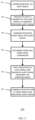
- FIG. 1 shows a method of generating an audio alert 100 by an audio system according to an embodiment.
- step 102 and alert signal may be generated.
- step 104 at least part of the alert signal that is generated in step 102 may be processed.
- the process alert signal may be analysed to determine an operating mode.
- a first operating mode might be termed to be a safe mode or fail safe mode of operation of the audio system.
- the second operating mode might be termed to be a normal operating mode of an audio system.
- a check of the operating mode may be made. If the operating mode is a safe mode (or first operating mode), then in step 112, the alert signal generated in step 102 may be directly output to a loudspeaker by an amplifier. Otherwise, in step 110 the processed or enhanced alert signal may be output to one or more loudspeakers via one or more amplifiers.
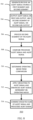
- Figure 2 shows a method of generating an audio alert 150 by an audio system according to an embodiment.
- an alert signal may be generated.
- the alert signal may be processed to generate a processed alert signal.
- the processed alert signal may be compared to the alert signal. In some examples this may be done by a cross-correlation of the processed alert signal with the alert signal. However, it will be appreciated that other methods of comparison may be used.
- an operating mode may be determined from the comparison. For example if the result of the comparison indicates that the processed alert signal has been somehow corrupted, then the operating mode may be considered to be in a first operating mode.
- the operating mode may be considered to be in a second operating mode.
- a weighting factor may be applied in step 160, dependent on the operating mode.
- the processed alert signal and the alert signal may be combined with the weighting factor in step 162.
- the weighting factors may be selected such that the combination of the signal may entirely or almost entirely consist of the alert signal generated in step 152, since the enhanced alert signal is considered to be corrupted, i.e. invalid.
- the weighting factors may be selected such that the combination of the signal may entirely or mostly consist of the processed alert signal generated in step 154, since the enhanced alert signal is valid.
- the method 150, 152 allows an audio system such as for example an infotainment system typically implemented in cars and other vehicles to provide audio enhanced and tuned alerts for example by including cabin equalisation, with a fallback mode to ensure the user alert is always played even if part of the system fails. This may avoid the use of for example a dedicated safety-controlled instrument cluster audio subsystem.
- FIG. 3 shows a digital audio system for generating an audio alert 200 according to an embodiment.
- the digital audio system may include an alert signal generator 202, a processor 206, a delay module 208, an analyser 216, and a combiner 220.
- the alert signal generator, the delay module 208, the analyser 216, and the combiner 220 may be located in a first system partition 210, which may also be referred to as the safe partition.
- the processor 206 may be located in a second system partition.
- An alert signal generator output 204 may be connected to an input of the processor 206 and an input of the delay module 208.
- the delay module output 214 may be connected to a first input of the combiner 220 and a first input of the analyser module 216.
- the processor output 212 may be connected to a second input of the analyser module 216 and a second input of the combiner 220.
- An analyser module output 218 may be connected to a control input of the combiner 220.
- the combiner output 222 may be connected via a digital to analog converter (not shown) to an amplifier 224.
- the amplifier output 226 may be connected to a loudspeaker 228.
- a user alert signal which may for example be a chime may be generated by the alert signal generator 202. This signal may also be referred to as a basic chime.
- the alert signal is provided to the audio processor 206, that is outside the safe partition 210.
- the audio processor 206 may apply signal enhancement.
- the processed user alert which may also be referred to as the enhanced user alert is output from the audio processor output 212 to the analyser module 216.
- the user alert signal may also be provided to the analyser module 216.
- the user alert signal is time-delayed by an amount ⁇ S by the delay module 208 which is equivalent to the expected time to process the user alert by the audio processor 206.
- the analyser module 216 may compute a consistency measure which may also be referred to as a validity measure, which is a measure that indicates whether the enhanced user alert is intact.
- the enhanced chime may consist of a single constant value or of random noise.
- One possible consistency or validity measure is the peak of the (absolute value of the) cross-correlation between the basic chime and the enhanced chime. Indeed, in the absence of processing and of an additional audio signal, the peak should be unity, and with functional processing, it should remain high, say above 0.8. In other examples, other cross-correlation measures, such as the phase-transform based cross-correlation may be used.
- the processed alert signal may be mixed with concurrent audio content by the processor 206.
- the peak value of the cross-correlation may decrease.
- the alert signal for example a chime is typically substantially louder than the concurrent audio content
- the cross-correlation is still a reliable consistency measure in the presence of concurrent audio, and should remain above a value for example 0.6 to indicate a subjectively intact enhanced chime.
- this information may replace the consistency measure, and the analysis module is not required.
- the validity of the audio processing in the non-safe partition can be evaluated using a parity check as consistency measure. If a parity bit is added to the processed alert signal in the non-safe partition at the end of the non-safe processing chain, the validity of this parity bit can be assessed in the safe partition 210. The validity of the parity bit which may be averaged across the most recent samples can then be checked in the safe partition to indicate whether the processed alert signal is valid i.e. intact.
- the parity bit may be computed on all but the least significant bit of the audio samples, and may be stored in the least significant bit of an audio sample. The parity bit may be determined for each sample, or after each block of N samples. Replacing the least significant bit every N samples may reduce the distortion in the audio.
- the parity bit may also be added to the processed alert signal when it includes other audio content. Since the parity bit is added at the end of the processing chain and hence, after the addition of the concurrent audio content, any parity error will indicate a corruption of the processed alert signal.
- bit patterns can be stored in the leastsignificant bit positions, e.g., a fixed alternating 0/1 bit pattern, or a code that is derived from the samples other than parity, such as a scrambled version of another bit of the samples.
- the audio system 200 may be considered to be in a first mode of operation which may be considered as a safe mode.
- a processed user alert may be considered invalid if it is corrupted to such an extent that it would no longer have the expected impact on the listener, i.e. the listener would not perceive the signal as a user alert, which may be important in a safety-critical situation.
- the audio system 200 may be considered to be in a second mode of operation which may be considered as a normal mode.
- the validity measure effectively defines the operating mode of the audio system 200.
- the validity measure is output to the combination module 220 which also receives the delayed basic user alert signal and the possibly corrupted processed user alert signal.
- the combination module 220 may either combine the two signals or select one of the two signals dependent on the validity measure, and the resulting alert output signal may be provided to the amplifier 224 and loudspeaker 228.
- the combination may be a simple selection, for example only the basic alert signal is output if the processed alert signal is invalid and only the processed alert signal is output if the processed alert signal is valid.
- the signals may be combined as a weighted sum of the alert signal and the processed alert signal.
- information may be available regarding the functionality of the non-safe partition, i.e. the part of the system not located in the safe partition 210.
- the analyser module 216 may be omitted, and the information regarding the functionality of the non-safe partition may be used as the validity measure.
- FIG. 4 shows a digital audio system for generating an audio alert 300 according to an embodiment.
- the digital audio system may include an alert signal generator 302, processor 306, a first delay module 308, a second delay module 330, a third delay module 332, an analyser 316, and a combiner 320.
- the alert signal generator, the delay module 208, the analyser 316, and the combiner 320 may be located in a first system partition 310.
- the processor 306 may be located in a second system partition.
- An alert signal generator output 304 may be connected to an input of the processor 306 and an input of the first delay module 308.
- the first delay module output 314 may be connected to an input of the second delay module 330 and a first input of the analyser module 316.
- the output 334 of the second delay module 330 may be connected to a first input of the combiner 320.
- the processor output 312 may be connected to an input of the third delay module 332 and second input of the analyser module 316.
- the output 336 of the third delay module 332 may be connected to a second input of the combiner 320.
- An output 318 of the analyser module 316 may be connected to a control input of the combiner 320.
- the combiner output 322 may be connected via a digital to analog converter (not shown) to an amplifier 324.
- the amplifier output 326 may be connected to a loudspeaker 328.
- a second delay time ⁇ L is added to the user alert signal by second delay module 330, which has already been delayed by first delay module 308 by a time ⁇ S .
- a second delay time ⁇ L is added to the processed user alert by third delay module 332. This allows for a lookahead mechanism, so that the combination module 320 can anticipate a change in consistency to reduce audible artifacts during transitions by, for example, transitioning from processed user alert to basic user alert before a corrupted segment of the delayed processed user alert reaches the combination module 320.
- the combiners 220, 320 may select the processed chime if the validity measure exceeds a certain threshold.
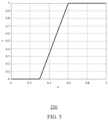
- the combiners 220, 320 may combine the user alert signal and processed user alert signal according to the graph 350 of figure 5 which shows the weighting factor or gain ⁇ on the y-axis varying between 0 and 1 and the normalized validity measure c on the x-axis varying between 0 and 1.
- a first threshold value for c the enhanced chime is presumed corrupt, and ⁇ is zero, due to which the basic chime is output.
- a second threshold for c the enhanced chime is presumed intact, and ⁇ is unity, due to which the enhanced chime is output.
- an uncertainty region which as illustrated in figure 3 may be for example between 0.3 and 0.6, a combination of the two chimes is output.
- the weighting factor ⁇ can also be asymmetrically temporally smoothed to reduce transition artifacts, e.g., by using a fast time constant for example between 50 milliseconds and 100 milliseconds to decrease to 0 (to play the basic alert signal), and a slower time constant, for example 0.5 seconds, to increase to 1 (to play the processed alert signal).
- a fast time constant for example between 50 milliseconds and 100 milliseconds to decrease to 0 (to play the basic alert signal)
- a slower time constant for example 0.5 seconds
- the weighted combination of the basic chime, s b , and the enhanced chime, se can be constructed in the frequency domain by taking the weighted combination of the magnitude spectrum, and the phase spectrum of the weighted combination in the time domain. This may prevent an attenuation of the signal output when the basic alert signal and the processed alert signal are not phase-aligned.
- FIG. 6 shows a digital audio system for generating an audio alert 400 according to an embodiment.
- the digital audio system may include an alert signal generator 402, processor 406, an analyser 416, and a combiner 420.
- the alert signal generator 402, the analyser 416, and the combiner 420 may be located in the first system partition 410.
- the processor 406 may be located in a second system partition.
- a first alert signal generator output 414 may be connected to an input of the combiner 420 and a first input of the analyser module 416.
- a second alert signal generator output 404 may be connected to an input of the processor 406.
- the processor output 412 may be connected to a second input of the analyser module 416 and a second input of the combiner 420.
- An analyser module output 418 may be connected to a control input of the combiner 420.
- the combiner output 422 may be connected via a digital to analog converter (not shown) to an amplifier 424.
- the amplifier output 426 may be connected to a loudspeaker 428.
- the first alert signal generator output 414 provides an alert signal which may be the same as the generator output of alert signal generators 202, 302.
- the alert signal may be considered to consist of a first (time) alert signal segment consisting of a first number of N samples followed by a second alert signal segment consisting of a second number of M samples.
- the second alert signal generator output 404 may output only the second segment of the alert signal corresponding to a lead time, which is typically set to be equal to the expected delay from the processing performed by the audio processor 306. In this way, the two signals at the input of the analyser module 416 and of the combination module 420 are synchronous. At the start of the basic chime, a first time segment equal to the lead time is skipped to obtain the second output signal of the generator module 402.
- the basic chime is played, and that after this time, the enhanced chime is played (if the non-safe partition is functional). If the lead time is sufficiently short (lower than 10ms), this will not be perceived as two separate signals.
- the audio system 400 may avoid the use of delay elements to synchronize the alert signal and processed alert signal, as done for example delay modules 208, 308, and/or to provide a look ahead function, as done for example by delay modules 330, 332.
- the audio system 400 may have a lower latency than audio system 200, 300 due to the absence of synchronisation and lookahead delays, which may be important in safety critical applications.
- the operation of audio system 400 may be further understood with reference to the graph 450 of figure 7 which shows an alert signal 456 having a first segment 452 and second segment 454. The duration of the first segment 452 may correspond to the delay through audio processor 406.
- the alert signal 456 is output on a first output and simultaneously the second segment 454 of the alert signal is output on a second output shown by waveform 458.
- Waveform 458 is processed by processor 406 and then after time t1 the processed signal is output shown by waveform 460. In this way the portion or segment of the original alert signal is time synchronized with the corresponding portion or segment of the processed alert signal before any combining.
- Figure 8 shows a method of generating an audio alert 500 by an audio system according to an embodiment, for example audio system 400.
- an alert signal may be generated.
- the alert signal may have a first segment and a second segment.
- the alert signal may be output from a first output and a second segment of the alert signal may be simultaneously output on a second output.
- the second segment of the alert signal may be processed generate a processed alert signal.
- the processed alert signal may be compared to the alert signal. In some examples, this comparison may be done by a cross-correlation of the processed alert signal with the alert signal or other method.
- an operating mode may be determined from the comparison.
- the operating mode may be considered to be in a first operating mode.
- the result of the comparison indicates that the processed alert signal has not been corrupted then the operating mode may be considered to be in a second operating mode.
- a weighting factor may be applied in step 512, dependent on the operating mode.
- the processed alert signal and the alert signal may be combined with the weighting factor in step 514.
- the weighting factors may be selected such that the combination of the signal may entirely or almost entirely consist of the alert signal generated in step 502, since the enhanced alert signal is considered to be corrupted, i.e. invalid.
- the weighting factors may be selected such that the combination of the signal may entirely or mostly consist of the processed alert signal generated in step 506, since the enhanced alert signal is valid.
- the alert signal and processed alert signals are not combined but instead a selection is made depending on the operating mode.
- Embodiments of the audio system and method may be implemented by hardware, software or a combination of hardware and software.
- the alert signal output may be a multi-channel output, and may be provided to multiple loudspeakers.
- the audio system may output a mono alert output signal played only on a single channel and loudspeaker in the safe operating mode.
- the loudspeaker used in the safe operating mode may be the closest loudspeaker to the driver, or with a fixed distribution across all loudspeakers. In the normal operating mode the processed alert signal may be processed so that it is louder for the intended user for example the vehicle driver.
- Embodiments describe a system and method that combines the safety-compliance of a separate audio system for critical user alerts, with the advanced audio processing that can be performed in the infotainment audio subsystem.
- This processing may comprise equalisation, dynamic range compression, noise-adaptive volume level, advanced mixing and 3D sound positioning.
- the audio processing involved may be performed on several separate partitions.
- One partition, the safe partition may be designed compliant to functional safety regulations, and another partition, the non-safe partition, may not necessarily be compliant to functional safety regulations.
- the basic user alert (e.g., a chime) may be generated in the safe partition.
- the basic user alert may be provided to the non-safe partition, which processes it to enhance the signal (e.g., cabin or other equalisation, dynamic range compression, noise-adaptive volume level, advanced mixing and 3D sound positioning).
- the processed alert is provided back to the safe partition.
- the processed alert is analysed to determine whether or not it has been corrupted. Indeed, if the non-safe partition has crashed, the processed alert could be all zeros, or it could contain random noise.
- the basic alert and processed alert may be combined, and sent to the output (to the amplifier and loudspeakers).
- the audio system and method described may guarantee the audio playback of a user alert (a chime), where signal enhancement processing is performed on the user alert (yielding the "enhanced chime") when possible. Since the signal enhancement processing is performed in the non-safe partition, the enhanced chime is only available when this non-safe partition is up and running. Therefore, when the non-safe partition has crashed, has not booted up yet, or is in any other way non-functional, the enhanced chime is not available, and the proposed system will play the basic chime. Otherwise, it will play the enhanced chime.
- the proposed system may be included in infotainment systems in vehicles, but it is not limited to that field. For example, industrial systems with audio alerts may also use the system and methods described.
- the set of instructions/method steps described above are implemented as functional and software instructions embodied as a set of executable instructions which are effected on a computer or machine which is programmed with and controlled by said executable instructions. Such instructions are loaded for execution on a processor (such as one or more CPUs).
- processor includes microprocessors, microcontrollers, processor modules or subsystems (including one or more microprocessors or microcontrollers), or other control or computing devices.
- a processor can refer to a single component or to plural components.
- the set of instructions/methods illustrated herein and data and instructions associated therewith are stored in respective storage devices, which are implemented as one or more non-transient machine or computer-readable or computer-usable storage media or mediums.
- Such computer-readable or computer usable storage medium or media is (are) considered to be part of an article (or article of manufacture).
- An article or article of manufacture can refer to any manufactured single component or multiple components.
- the non-transient machine or computer usable media or mediums as defined herein excludes signals, but such media or mediums may be capable of receiving and processing information from signals and/or other transient mediums.
- Example embodiments of the material discussed in this specification can be implemented in whole or in part through network, computer, or data based devices and/or services. These may include cloud, internet, intranet, mobile, desktop, processor, look-up table, microcontroller, consumer equipment, infrastructure, or other enabling devices and services. As may be used herein and in the claims, the following non-exclusive definitions are provided.
- one or more instructions or steps discussed herein are automated.
- the terms automated or automatically mean controlled operation of an apparatus, system, and/or process using computers and/or mechanical/electrical devices without the necessity of human intervention, observation, effort and/or decision.
Landscapes
- Engineering & Computer Science (AREA)
- Chemical & Material Sciences (AREA)
- Combustion & Propulsion (AREA)
- Transportation (AREA)
- Mechanical Engineering (AREA)
- Physics & Mathematics (AREA)
- Acoustics & Sound (AREA)
- Signal Processing (AREA)
- Electromagnetism (AREA)
- General Physics & Mathematics (AREA)
- Circuit For Audible Band Transducer (AREA)
Abstract
Description
- This disclosure describes a system and method for audio alert generation.
- In a safety-critical environment, auditive warning signals are often crucial elements to alert the user. There are several recommendations and standards describing the requirements of safety-critical systems for example IEC61508, ISO26262. In an automotive context, where elaborate audio subsystems are becoming a very prominent feature due to the growing importance of in-car infotainment, the existing audio system including loudspeakers, amplifiers, microphones, signal enhancement may be used to generate user alerts. However, for safety-critical user alerts, this would require the inclusion of the complete infotainment subsystem into the tightly-controlled safety chain, spanning not only the loudspeakers and amplifiers, but also, and more importantly, the hardware platforms where digital signal processing is performed in the audio chain. Since this may result in a considerable investment in the development of the audio subsystem and of all the software modules and hardware platforms involved, it is typical to use a dedicated, separate and smaller audio subsystem, comprising a micro-controller for generating the alert with little or no digital signal processing, an amplifier and a loudspeaker.
- This safety-controlled dedicated audio subsystem can be positioned, e.g., under the instrumentation panel, which leads to size constraints, and consequently, the combination of a single amplifier with a single small loudspeaker is used.
- Various aspects of the disclosure are defined in the accompanying claims. In a first aspect there is provided a method of generating an audible alert by a digital audio system configured to operate in a first operating mode and a second operating mode, the method comprising: generating or receiving an alert signal; generating a processed alert signal by processing at least a segment of the alert signal; analysing the processed alert signal to define whether the digital audio system operates in the first operating mode or the second operating mod; and in the first operating mode, generating an alert output signal comprising the alert signal; and in the second operating mode, generating an alert output signal comprising the processed alert signal.
- In one or more embodiments, generating the alert output signal may further comprise combining the alert signal and the processed alert signal.
- In one or more embodiments, generating the alert output signal may further comprise generating a first alert signal segment and a second alert signal segment, and generating the processed alert signal comprises processing the second alert signal segment.
- In one or more embodiments, the method may further comprise at least one of (i) delaying the alert signal before the analysing and combining, and (ii) delaying the alert signal and the processed alert signal before the combining.
- In one or more embodiments, analysing the processed alert signal may further comprise determining a validity of the processed alert signal.
- In one or more embodiments, the method may further comprise determining a validity of the processed alert signal from a comparison of the processed alert signal and the alert signal.
- In one or more embodiments, the method may further comprise determining the validity of the processed alert signal from the cross-correlation of the alert signal and the processed alert signal.
- In one or more embodiments, generating a processed alert signal may further comprise replacing at least one bit in a sample of the alert signal with a parity bit, and wherein determining a validity of the processed alert signal comprises checking the parity of the alert signal sample.
- In one or more embodiments, the method may further comprise configuring the digital audio system in the first operating mode in response to determining that the processed alert signal is invalid, and configuring the digital audio system in the second operating mode in response to determining that the processed alert signal is valid.
- In one or more embodiments, the audio system may comprise a first system partition configured to operate at least in the first operating mode and a second system partition, and the method may further comprise: generating or receiving the alert signal in the first system partition; generating the processed alert signal in the second system partition; analysing the processed alert signal in the first system partition; generating the alert output signal in the first system partition.
- In a second aspect, there is provided digital audio system configured to operate in a first operating mode and a second operating mode, the digital audio system comprising: an alert signal generator configured to generate an alert signal; a processor coupled to the alert signal generator and configured to generate an processed alert signal by processing at least a segment of the alert signal; an analyser coupled to the processor and the alert signal generator and configured to analyse the processed alert signal to define whether the digital audio system operates in the first operating mode or the second operating mode; and a combiner coupled to the processor, the alert signal generator and the analyser, the combiner configured in the first operating mode to output an alert output signal comprising the alert signal, and in the second operating mode to output an alert output signal comprising the processed alert signal.
- In one or more embodiments, the digital audio system may comprise a first system partition and a second system partition, wherein the alert signal generator, the analyser and the combiner are located in the first system partition and the processor is located in the second system partition.
- In one or more embodiments, the combiner may be further configured to combine the alert signal and the processed alert signal, and to output an alert output signal comprising the combined alert signal and processed alert signal.
- In one or more embodiments, the digital audio system may comprise: a first delay module arranged between the alert signal generator output and the combiner and analyser and configured to delay the alert signal before the analysing and combining.
- In one or more embodiments, the alert signal generator may comprise a first alert signal generator output coupled to the combiner and a second alert signal generator output coupled to the processor and wherein the alert signal comprises a first alert signal segment and a second alert signal segment wherein the alert signal generator is configured to output the first alert signal segment followed by the second alert signal segment on the first alert signal generator output and to output the second alert signal segment on the second alert signal generator output.
- In one or more embodiments, the digital audio system may comprise: a second delay module arranged between the first delay module and the combiner; and a third delay module arranged between a processor output and the combiner.
- In one or more embodiments, the analyser may be further configured to determine a validity of the processed alert signal.
- In one or more embodiments, the digital audio system may be further configured to determine the validity of the processed alert signal from a cross-correlation of the alert signal and the processed alert signal.
- In one or more embodiments, the processor may be further configured to generate an processed alert signal by adding a parity bit to a processed alert signal sample and to determine the validity of the processed alert signal by a parity check of the processed alert signal sample.
- In a third aspect, there is provided a non-transitory computer readable media comprising a computer program comprising computer executable instructions which, when executed by a processor in a digital audio system configured to operate in a first operating mode and a second operating mode, causes the processor to perform a method for generating an audible alert, the method comprising: generating or receiving an alert signal; generating a processed alert signal by processing at least a segment of the alert signal; analysing the processed alert signal to define whether the digital audio system operates in the first operating mode or the second operating mode; and in the first operating mode, generating an alert output signal comprising the alert signal; and in the second operating mode, generating an alert output signal comprising the processed alert signal.
- In the figures and description like reference numerals refer to like features. Embodiments are now described in detail, by way of example only, illustrated by the accompanying drawings in which:
-
Figure 1 shows a method of generating an audio alert according to an embodiment. -
Figure 2 illustrates a method of generating an audio alert according to an embodiment. -
Figure 3 shows an audio system for generating an audio alert according to an embodiment. -
Figure 4 illustrates an audio system for generating an audio alert according to an embodiment. -
Figure 5 shows a graph illustrating an example variation of the weighting factor or gain factor versus the validity measure value. -
Figure 6 shows an audio system for generating an audio alert according to an embodiment. -
Figure 7 shows a graph illustrating an example of the waveform generated by the audio system offigure 6 . -
Figure 8 shows a method of generating an audio alert according to an embodiment. -
Figure 1 shows a method of generating anaudio alert 100 by an audio system according to an embodiment. Instep 102 and alert signal may be generated. Instep 104 at least part of the alert signal that is generated instep 102 may be processed. Instep 106, the process alert signal may be analysed to determine an operating mode. In some examples, a first operating mode might be termed to be a safe mode or fail safe mode of operation of the audio system. In some examples the second operating mode might be termed to be a normal operating mode of an audio system. In step 108 a check of the operating mode may be made. If the operating mode is a safe mode (or first operating mode), then instep 112, the alert signal generated instep 102 may be directly output to a loudspeaker by an amplifier. Otherwise, instep 110 the processed or enhanced alert signal may be output to one or more loudspeakers via one or more amplifiers. -
Figure 2 shows a method of generating anaudio alert 150 by an audio system according to an embodiment. Instep 152 an alert signal may be generated. Instep 154 the alert signal may be processed to generate a processed alert signal. Instep 156 the processed alert signal may be compared to the alert signal. In some examples this may be done by a cross-correlation of the processed alert signal with the alert signal. However, it will be appreciated that other methods of comparison may be used. Instep 158 an operating mode may be determined from the comparison. For example if the result of the comparison indicates that the processed alert signal has been somehow corrupted, then the operating mode may be considered to be in a first operating mode. Alternatively if the result of the comparison indicates that the processed alert signal has not been corrupted, then the operating mode may be considered to be in a second operating mode. A weighting factor may be applied instep 160, dependent on the operating mode. The processed alert signal and the alert signal may be combined with the weighting factor instep 162. For example in the first operating mode the weighting factors may be selected such that the combination of the signal may entirely or almost entirely consist of the alert signal generated instep 152, since the enhanced alert signal is considered to be corrupted, i.e. invalid. In the second operating mode, the weighting factors may be selected such that the combination of the signal may entirely or mostly consist of the processed alert signal generated instep 154, since the enhanced alert signal is valid. - The
method -
Figure 3 shows a digital audio system for generating anaudio alert 200 according to an embodiment. The digital audio system may include analert signal generator 202, aprocessor 206, adelay module 208, ananalyser 216, and acombiner 220. The alert signal generator, thedelay module 208, theanalyser 216, and thecombiner 220 may be located in afirst system partition 210, which may also be referred to as the safe partition. Theprocessor 206 may be located in a second system partition. An alertsignal generator output 204 may be connected to an input of theprocessor 206 and an input of thedelay module 208. Thedelay module output 214 may be connected to a first input of thecombiner 220 and a first input of theanalyser module 216. Theprocessor output 212 may be connected to a second input of theanalyser module 216 and a second input of thecombiner 220. Ananalyser module output 218 may be connected to a control input of thecombiner 220. Thecombiner output 222 may be connected via a digital to analog converter (not shown) to anamplifier 224. Theamplifier output 226 may be connected to aloudspeaker 228. - In operation, a user alert signal which may for example be a chime may be generated by the
alert signal generator 202. This signal may also be referred to as a basic chime. The alert signal is provided to theaudio processor 206, that is outside thesafe partition 210. Theaudio processor 206 may apply signal enhancement. The processed user alert which may also be referred to as the enhanced user alert is output from theaudio processor output 212 to theanalyser module 216. The user alert signal may also be provided to theanalyser module 216. Optionally the user alert signal is time-delayed by an amount ΔS by thedelay module 208 which is equivalent to the expected time to process the user alert by theaudio processor 206. Theanalyser module 216 may compute a consistency measure which may also be referred to as a validity measure, which is a measure that indicates whether the enhanced user alert is intact. - If the non-safe partition has crashed, the enhanced chime may consist of a single constant value or of random noise.
- One possible consistency or validity measure is the peak of the (absolute value of the) cross-correlation between the basic chime and the enhanced chime. Indeed, in the absence of processing and of an additional audio signal, the peak should be unity, and with functional processing, it should remain high, say above 0.8. In other examples, other cross-correlation measures, such as the phase-transform based cross-correlation may be used.
- In some examples, the processed alert signal may be mixed with concurrent audio content by the
processor 206. In these examples the peak value of the cross-correlation may decrease. However, because the alert signal, for example a chime is typically substantially louder than the concurrent audio content, the cross-correlation is still a reliable consistency measure in the presence of concurrent audio, and should remain above a value for example 0.6 to indicate a subjectively intact enhanced chime. - If information is available regarding the proper functioning of the non-safe partition, at least with respect to the processing of the chime, this information may replace the consistency measure, and the analysis module is not required.
- Alternatively, in some examples, the validity of the audio processing in the non-safe partition can be evaluated using a parity check as consistency measure. If a parity bit is added to the processed alert signal in the non-safe partition at the end of the non-safe processing chain, the validity of this parity bit can be assessed in the
safe partition 210. The validity of the parity bit which may be averaged across the most recent samples can then be checked in the safe partition to indicate whether the processed alert signal is valid i.e. intact. The parity bit may be computed on all but the least significant bit of the audio samples, and may be stored in the least significant bit of an audio sample. The parity bit may be determined for each sample, or after each block of N samples. Replacing the least significant bit every N samples may reduce the distortion in the audio. The parity bit may also be added to the processed alert signal when it includes other audio content. Since the parity bit is added at the end of the processing chain and hence, after the addition of the concurrent audio content, any parity error will indicate a corruption of the processed alert signal. - Alternatively, in other examples other bit patterns can be stored in the leastsignificant bit positions, e.g., a fixed alternating 0/1 bit pattern, or a code that is derived from the samples other than parity, such as a scrambled version of another bit of the samples.
- If the validity measure indicates that the processed user alert is invalid, then the
audio system 200 may be considered to be in a first mode of operation which may be considered as a safe mode. A processed user alert may be considered invalid if it is corrupted to such an extent that it would no longer have the expected impact on the listener, i.e. the listener would not perceive the signal as a user alert, which may be important in a safety-critical situation. If the validity measure indicates that the processed user alert is valid, then theaudio system 200 may be considered to be in a second mode of operation which may be considered as a normal mode. The validity measure effectively defines the operating mode of theaudio system 200. The validity measure is output to thecombination module 220 which also receives the delayed basic user alert signal and the possibly corrupted processed user alert signal. Thecombination module 220 may either combine the two signals or select one of the two signals dependent on the validity measure, and the resulting alert output signal may be provided to theamplifier 224 andloudspeaker 228. In some examples the combination may be a simple selection, for example only the basic alert signal is output if the processed alert signal is invalid and only the processed alert signal is output if the processed alert signal is valid. In some examples, the signals may be combined as a weighted sum of the alert signal and the processed alert signal. - In some examples, information may be available regarding the functionality of the non-safe partition, i.e. the part of the system not located in the
safe partition 210. In these examples, theanalyser module 216 may be omitted, and the information regarding the functionality of the non-safe partition may be used as the validity measure. -
Figure 4 shows a digital audio system for generating anaudio alert 300 according to an embodiment. The digital audio system may include analert signal generator 302,processor 306, afirst delay module 308, asecond delay module 330, athird delay module 332, ananalyser 316, and acombiner 320. The alert signal generator, thedelay module 208, theanalyser 316, and thecombiner 320 may be located in afirst system partition 310. Theprocessor 306 may be located in a second system partition. - An alert
signal generator output 304 may be connected to an input of theprocessor 306 and an input of thefirst delay module 308. The firstdelay module output 314 may be connected to an input of thesecond delay module 330 and a first input of theanalyser module 316. Theoutput 334 of thesecond delay module 330 may be connected to a first input of thecombiner 320. - The
processor output 312 may be connected to an input of thethird delay module 332 and second input of theanalyser module 316. Theoutput 336 of thethird delay module 332 may be connected to a second input of thecombiner 320. Anoutput 318 of theanalyser module 316 may be connected to a control input of thecombiner 320. Thecombiner output 322 may be connected via a digital to analog converter (not shown) to anamplifier 324. Theamplifier output 326 may be connected to aloudspeaker 328. - In operation, the function of the
digital audio system 300 is similar todigital audio system 200. A second delay time ΔL is added to the user alert signal bysecond delay module 330, which has already been delayed byfirst delay module 308 by a time ΔS. A second delay time ΔL is added to the processed user alert bythird delay module 332. This allows for a lookahead mechanism, so that thecombination module 320 can anticipate a change in consistency to reduce audible artifacts during transitions by, for example, transitioning from processed user alert to basic user alert before a corrupted segment of the delayed processed user alert reaches thecombination module 320. - In some examples of digital
audio systems combiners combiners 
combiners graph 350 offigure 5 which shows the weighting factor or gain γ on the y-axis varying between 0 and 1 and the normalized validity measure c on the x-axis varying between 0 and 1. Below a first threshold value for c, the enhanced chime is presumed corrupt, and γ is zero, due to which the basic chime is output. Above a second threshold for c, the enhanced chime is presumed intact, and γ is unity, due to which the enhanced chime is output. In an uncertainty region which as illustrated infigure 3 may be for example between 0.3 and 0.6, a combination of the two chimes is output. The weighting factor γ can also be asymmetrically temporally smoothed to reduce transition artifacts, e.g., by using a fast time constant for example between 50 milliseconds and 100 milliseconds to decrease to 0 (to play the basic alert signal), and a slower time constant, for example 0.5 seconds, to increase to 1 (to play the processed alert signal). - In another example, the weighted combination of the basic chime, sb, and the enhanced chime, se, can be constructed in the frequency domain by taking the weighted combination of the magnitude spectrum, and the phase spectrum of the weighted combination in the time domain. This may prevent an attenuation of the signal output when the basic alert signal and the processed alert signal are not phase-aligned.
-
Figure 6 shows a digital audio system for generating anaudio alert 400 according to an embodiment. The digital audio system may include analert signal generator 402,processor 406, ananalyser 416, and acombiner 420. Thealert signal generator 402, theanalyser 416, and thecombiner 420 may be located in the first system partition 410. Theprocessor 406 may be located in a second system partition. A first alertsignal generator output 414 may be connected to an input of thecombiner 420 and a first input of theanalyser module 416. A second alertsignal generator output 404 may be connected to an input of theprocessor 406. Theprocessor output 412 may be connected to a second input of theanalyser module 416 and a second input of thecombiner 420. Ananalyser module output 418 may be connected to a control input of thecombiner 420. Thecombiner output 422 may be connected via a digital to analog converter (not shown) to anamplifier 424. Theamplifier output 426 may be connected to aloudspeaker 428. - In operation, the first alert
signal generator output 414 provides an alert signal which may be the same as the generator output ofalert signal generators signal generator output 404 may output only the second segment of the alert signal corresponding to a lead time, which is typically set to be equal to the expected delay from the processing performed by theaudio processor 306. In this way, the two signals at the input of theanalyser module 416 and of thecombination module 420 are synchronous. At the start of the basic chime, a first time segment equal to the lead time is skipped to obtain the second output signal of thegenerator module 402. This means that for a time equal to the processing time of the non-safe module, the basic chime is played, and that after this time, the enhanced chime is played (if the non-safe partition is functional). If the lead time is sufficiently short (lower than 10ms), this will not be perceived as two separate signals. - By not outputting the complete alert signal to the processor, the
audio system 400 may avoid the use of delay elements to synchronize the alert signal and processed alert signal, as done forexample delay modules delay modules audio system 400 may have a lower latency thanaudio system audio system 400 may be further understood with reference to thegraph 450 offigure 7 which shows analert signal 456 having afirst segment 452 andsecond segment 454. The duration of thefirst segment 452 may correspond to the delay throughaudio processor 406. At time t0, thealert signal 456 is output on a first output and simultaneously thesecond segment 454 of the alert signal is output on a second output shown bywaveform 458.Waveform 458 is processed byprocessor 406 and then after time t1 the processed signal is output shown bywaveform 460. In this way the portion or segment of the original alert signal is time synchronized with the corresponding portion or segment of the processed alert signal before any combining. -
Figure 8 shows a method of generating anaudio alert 500 by an audio system according to an embodiment, forexample audio system 400. Instep 502 an alert signal may be generated. The alert signal may have a first segment and a second segment. Instep 504 the alert signal may be output from a first output and a second segment of the alert signal may be simultaneously output on a second output. Instep 506, the second segment of the alert signal may be processed generate a processed alert signal. Instep 508 the processed alert signal may be compared to the alert signal. In some examples, this comparison may be done by a cross-correlation of the processed alert signal with the alert signal or other method. Instep 510 an operating mode may be determined from the comparison. For example if the result of the comparison indicates that the processed alert signal has been somehow corrupted, then the operating mode may be considered to be in a first operating mode. Alternatively if the result of the comparison indicates that the processed alert signal has not been corrupted then the operating mode may be considered to be in a second operating mode. A weighting factor may be applied instep 512, dependent on the operating mode. The processed alert signal and the alert signal may be combined with the weighting factor instep 514. For example in the first operating mode the weighting factors may be selected such that the combination of the signal may entirely or almost entirely consist of the alert signal generated instep 502, since the enhanced alert signal is considered to be corrupted, i.e. invalid. In the second operating mode, the weighting factors may be selected such that the combination of the signal may entirely or mostly consist of the processed alert signal generated instep 506, since the enhanced alert signal is valid. In some examples the alert signal and processed alert signals are not combined but instead a selection is made depending on the operating mode. - Embodiments of the audio system and method may be implemented by hardware, software or a combination of hardware and software. In some embodiments, the alert signal output may be a multi-channel output, and may be provided to multiple loudspeakers. In some examples, the audio system may output a mono alert output signal played only on a single channel and loudspeaker in the safe operating mode. For embodiments included in an automotive infotainment system, the loudspeaker used in the safe operating mode may be the closest loudspeaker to the driver, or with a fixed distribution across all loudspeakers. In the normal operating mode the processed alert signal may be processed so that it is louder for the intended user for example the vehicle driver.
- Embodiments describe a system and method that combines the safety-compliance of a separate audio system for critical user alerts, with the advanced audio processing that can be performed in the infotainment audio subsystem. This processing may comprise equalisation, dynamic range compression, noise-adaptive volume level, advanced mixing and 3D sound positioning.
- In embodiment, the audio processing involved may be performed on several separate partitions. One partition, the safe partition, may be designed compliant to functional safety regulations, and another partition, the non-safe partition, may not necessarily be compliant to functional safety regulations. The basic user alert (e.g., a chime) may be generated in the safe partition. The basic user alert may be provided to the non-safe partition, which processes it to enhance the signal (e.g., cabin or other equalisation, dynamic range compression, noise-adaptive volume level, advanced mixing and 3D sound positioning). The processed alert is provided back to the safe partition. The processed alert is analysed to determine whether or not it has been corrupted. Indeed, if the non-safe partition has crashed, the processed alert could be all zeros, or it could contain random noise. Depending on the outcome of the analysis, the basic alert and processed alert may be combined, and sent to the output (to the amplifier and loudspeakers).
- The audio system and method described may guarantee the audio playback of a user alert (a chime), where signal enhancement processing is performed on the user alert (yielding the "enhanced chime") when possible. Since the signal enhancement processing is performed in the non-safe partition, the enhanced chime is only available when this non-safe partition is up and running. Therefore, when the non-safe partition has crashed, has not booted up yet, or is in any other way non-functional, the enhanced chime is not available, and the proposed system will play the basic chime. Otherwise, it will play the enhanced chime. The proposed system may be included in infotainment systems in vehicles, but it is not limited to that field. For example, industrial systems with audio alerts may also use the system and methods described.
- In some example embodiments the set of instructions/method steps described above are implemented as functional and software instructions embodied as a set of executable instructions which are effected on a computer or machine which is programmed with and controlled by said executable instructions. Such instructions are loaded for execution on a processor (such as one or more CPUs). The term processor includes microprocessors, microcontrollers, processor modules or subsystems (including one or more microprocessors or microcontrollers), or other control or computing devices. A processor can refer to a single component or to plural components.
- In other examples, the set of instructions/methods illustrated herein and data and instructions associated therewith are stored in respective storage devices, which are implemented as one or more non-transient machine or computer-readable or computer-usable storage media or mediums. Such computer-readable or computer usable storage medium or media is (are) considered to be part of an article (or article of manufacture). An article or article of manufacture can refer to any manufactured single component or multiple components. The non-transient machine or computer usable media or mediums as defined herein excludes signals, but such media or mediums may be capable of receiving and processing information from signals and/or other transient mediums.
- Example embodiments of the material discussed in this specification can be implemented in whole or in part through network, computer, or data based devices and/or services. These may include cloud, internet, intranet, mobile, desktop, processor, look-up table, microcontroller, consumer equipment, infrastructure, or other enabling devices and services. As may be used herein and in the claims, the following non-exclusive definitions are provided.
- In one example, one or more instructions or steps discussed herein are automated. The terms automated or automatically (and like variations thereof) mean controlled operation of an apparatus, system, and/or process using computers and/or mechanical/electrical devices without the necessity of human intervention, observation, effort and/or decision.
- Although the appended claims are directed to particular combinations of features, it should be understood that the scope of the disclosure of the present invention also includes any novel feature or any novel combination of features disclosed herein either explicitly or implicitly or any generalisation thereof, whether or not it relates to the same invention as presently claimed in any claim and whether or not it mitigates any or all of the same technical problems as does the present invention.
- Features which are described in the context of separate embodiments may also be provided in combination in a single embodiment. Conversely, various features which are, for brevity, described in the context of a single embodiment, may also be provided separately or in any suitable sub combination.
- The applicant hereby gives notice that new claims may be formulated to such features and/or combinations of such features during the prosecution of the present application or of any further application derived therefrom.
- For the sake of completeness it is also stated that the term "comprising" does not exclude other elements or steps, the term "a" or "an" does not exclude a plurality, a single processor or other unit may fulfil the functions of several means recited in the claims and reference signs in the claims shall not be construed as limiting the scope of the claims.
Claims (15)
- A method of generating an audible alert by a digital audio system configured to operate in a first operating mode and a second operating mode, the method comprising:generating or receiving an alert signal;generating a processed alert signal by processing at least a segment of the alert signal;analysing the processed alert signal to define whether the digital audio system operates in the first operating mode or the second operating mode; andin the first operating mode, generating an alert output signal comprising the alert signal; andin the second operating mode, generating an alert output signal comprising the processed alert signal.
- The method of claim 1, wherein in the second operating mode, generating the alert output signal further comprises combining the alert signal and the processed alert signal.
- The method of claim 2, wherein generating the alert output signal further comprises generating a first alert signal segment and a second alert signal segment, and generating the processed alert signal comprises processing the second alert signal segment.
- The method of claim 2 further comprising:
at least one of (i) delaying the alert signal before the analysing and combining, and (ii) delaying the alert signal and the processed alert signal before the combining. - The method of any preceding claim, wherein analysing the processed alert signal further comprises determining a validity of the processed alert signal.
- The method of claim 4 further comprising: determining a validity of the processed alert signal from a comparison of the processed alert signal and the alert signal.
- The method of claim 5 or 6, further comprising: determining the validity of the processed alert signal from the cross-correlation of the alert signal and the processed alert signal.
- The method of any of claims 5 to 7, wherein generating a processed alert signal further comprises replacing at least one bit in a sample of the alert signal with a parity bit, and wherein determining a validity of the processed alert signal comprises checking the parity of the alert signal sample.
- The method of any of claims 5 to 8, further comprising: configuring the digital audio system in the first operating mode in response to determining that the processed alert signal is invalid, and configuring the digital audio system in the second operating mode in response to determining that the processed alert signal is valid.
- The method of any preceding claim, wherein the audio system comprises a first system partition configured to operate at least in the first operating mode and a second system partition, the method comprising:generating or receiving the alert signal in the first system partition;generating the processed alert signal in the second system partition;analysing the processed alert signal in the first system partition;generating the alert output signal in the first system partition.
- A digital audio system configured to operate in a first operating mode and a second operating mode, the digital audio system comprising:an alert signal generator configured to generate an alert signal;a processor coupled to the alert signal generator and configured to generate an processed alert signal by processing at least a segment of the alert signal;an analyser coupled to the processor and the alert signal generator and configured to analyse the processed alert signal to define whether the digital audio system operates in the first operating mode or the second operating mode; anda combiner coupled to the processor, the alert signal generator and the analyser, the combiner configured in the first operating mode to output an alert output signal comprising the alert signal, and in the second operating mode to output an alert output signal comprising the processed alert signal.
- The digital audio system of claim 11 comprising a first system partition and a second system partition, wherein the alert signal generator, the analyser and the combiner are located in the first system partition and the processor is located in the second system partition.
- The digital audio system of claim 11 or 12, wherein the combiner is further configured to combine the alert signal and the processed alert signal, and to output an alert output signal comprising the combined alert signal and processed alert signal.
- The digital audio system of any of claims 11 to 13 further comprising:
a first delay module arranged between the alert signal generator output and the combiner and analyser and configured to delay the alert signal before the analysing and combining. - The digital audio system of any of claims 11 to 13, wherein the alert signal generator comprises a first alert signal generator output coupled to the combiner and a second alert signal generator output coupled to the processor and wherein the alert signal comprises a first alert signal segment and a second alert signal segment wherein the alert signal generator is configured to output the first alert signal segment followed by the second alert signal segment on the first alert signal generator output and to output the second alert signal segment on the second alert signal generator output.
Priority Applications (2)
| Application Number | Priority Date | Filing Date | Title |
|---|---|---|---|
| EP22172061.8A EP4273823B1 (en) | 2022-05-06 | 2022-05-06 | Audio alert generation method and apparatus |
| US18/310,642 US12337687B2 (en) | 2022-05-06 | 2023-05-02 | Audio alert generation method and apparatus |
Applications Claiming Priority (1)
| Application Number | Priority Date | Filing Date | Title |
|---|---|---|---|
| EP22172061.8A EP4273823B1 (en) | 2022-05-06 | 2022-05-06 | Audio alert generation method and apparatus |
Publications (2)
| Publication Number | Publication Date |
|---|---|
| EP4273823A1 true EP4273823A1 (en) | 2023-11-08 |
| EP4273823B1 EP4273823B1 (en) | 2025-04-23 |
Family
ID=81598005
Family Applications (1)
| Application Number | Title | Priority Date | Filing Date |
|---|---|---|---|
| EP22172061.8A Active EP4273823B1 (en) | 2022-05-06 | 2022-05-06 | Audio alert generation method and apparatus |
Country Status (2)
| Country | Link |
|---|---|
| US (1) | US12337687B2 (en) |
| EP (1) | EP4273823B1 (en) |
Citations (2)
| Publication number | Priority date | Publication date | Assignee | Title |
|---|---|---|---|---|
| EP3382663A1 (en) * | 2017-03-31 | 2018-10-03 | Magneti Marelli S.p.A. | Method for generating and propagating in a vehicle an audio alarm warning and corresponding apparatus |
| US11120642B2 (en) * | 2018-06-27 | 2021-09-14 | Intel Corporation | Functional safety critical audio system for autonomous and industrial applications |
Family Cites Families (6)
| Publication number | Priority date | Publication date | Assignee | Title |
|---|---|---|---|---|
| US9661416B2 (en) * | 2015-08-24 | 2017-05-23 | Harman International Industries, Inc. | Techniques for optimizing the polarities of audio input channels |
| EP3229371B1 (en) * | 2016-04-06 | 2020-03-11 | Nxp B.V. | Audio amplifier system |
| US9832007B2 (en) * | 2016-04-14 | 2017-11-28 | Ibiquity Digital Corporation | Time-alignment measurement for hybrid HD radio™ technology |
| EP3309981B1 (en) | 2016-10-17 | 2021-06-02 | Nxp B.V. | Audio processing circuit, audio unit, integrated circuit and method for blending |
| US10012691B1 (en) * | 2017-11-07 | 2018-07-03 | Qualcomm Incorporated | Audio output diagnostic circuit |
| US11308791B2 (en) | 2018-12-28 | 2022-04-19 | Intel Corporation | Methods, systems and apparatus to use audio return path for functional safety validation |
-
2022
- 2022-05-06 EP EP22172061.8A patent/EP4273823B1/en active Active
-
2023
- 2023-05-02 US US18/310,642 patent/US12337687B2/en active Active
Patent Citations (2)
| Publication number | Priority date | Publication date | Assignee | Title |
|---|---|---|---|---|
| EP3382663A1 (en) * | 2017-03-31 | 2018-10-03 | Magneti Marelli S.p.A. | Method for generating and propagating in a vehicle an audio alarm warning and corresponding apparatus |
| US11120642B2 (en) * | 2018-06-27 | 2021-09-14 | Intel Corporation | Functional safety critical audio system for autonomous and industrial applications |
Also Published As
| Publication number | Publication date |
|---|---|
| US20230356593A1 (en) | 2023-11-09 |
| US12337687B2 (en) | 2025-06-24 |
| EP4273823B1 (en) | 2025-04-23 |
Similar Documents
| Publication | Publication Date | Title |
|---|---|---|
| EP3503095A1 (en) | Hybrid waveform-coded and parametric-coded speech enhancement | |
| US7162045B1 (en) | Sound processing method and apparatus | |
| US8892228B2 (en) | Concealing audio artifacts | |
| RU2010136357A (en) | MIXING INCOMING INFORMATION FLOWS AND GENERATING THE EXITING INFORMATION FLOW | |
| IL180046A (en) | Apparatus and method for generating multi-channel synthesizer control signal and apparatus and method for multi-channel synthesizing | |
| US10057681B2 (en) | Entertainment audio processing | |
| KR20110063807A (en) | Bilateral time delay restoration system and method | |
| JP2011188467A (en) | Broadcast receiving apparatus and method of determining presence of noise for broadcast receiving apparatus | |
| US9792925B2 (en) | Signal processing device, signal processing method and signal processing program | |
| US12337687B2 (en) | Audio alert generation method and apparatus | |
| CN110543428B (en) | Application system testing method and device | |
| US12382234B2 (en) | Perceptual optimization of magnitude and phase for time-frequency and softmask source separation systems | |
| WO2021059718A1 (en) | Signal processing device, signal processing method, and program | |
| JP5232121B2 (en) | Signal processing device | |
| US12573412B2 (en) | Audio processing system and method | |
| JP2004021224A (en) | Method, system and computer program for digital voice processing | |
| CN108962268B (en) | Method and apparatus for determining monophonic audio | |
| US20040071301A1 (en) | Mixing method, mixing apparatus, and program for implementing the mixing method | |
| US20070050676A1 (en) | Software testing device and method, and computer readable recording medium for recording program executing software testing | |
| EP3386126A1 (en) | Audio processor | |
| US20210152939A1 (en) | Audio system speaker virtualization | |
| JP4947154B2 (en) | Image processing apparatus, image processing method, and image processing program | |
| US9661416B2 (en) | Techniques for optimizing the polarities of audio input channels | |
| US11750975B2 (en) | Signal processing device, signal processing method, and recording medium | |
| US20190158956A1 (en) | Method for enhancing sound volume and system for enhancing sound volume |
Legal Events
| Date | Code | Title | Description |
|---|---|---|---|
| PUAI | Public reference made under article 153(3) epc to a published international application that has entered the european phase |
Free format text: ORIGINAL CODE: 0009012 |
|
| STAA | Information on the status of an ep patent application or granted ep patent |
Free format text: STATUS: THE APPLICATION HAS BEEN PUBLISHED |
|
| AK | Designated contracting states |
Kind code of ref document: A1 Designated state(s): AL AT BE BG CH CY CZ DE DK EE ES FI FR GB GR HR HU IE IS IT LI LT LU LV MC MK MT NL NO PL PT RO RS SE SI SK SM TR |
|
| STAA | Information on the status of an ep patent application or granted ep patent |
Free format text: STATUS: REQUEST FOR EXAMINATION WAS MADE |
|
| 17P | Request for examination filed |
Effective date: 20240508 |
|
| RBV | Designated contracting states (corrected) |
Designated state(s): AL AT BE BG CH CY CZ DE DK EE ES FI FR GB GR HR HU IE IS IT LI LT LU LV MC MK MT NL NO PL PT RO RS SE SI SK SM TR |
|
| GRAP | Despatch of communication of intention to grant a patent |
Free format text: ORIGINAL CODE: EPIDOSNIGR1 |
|
| STAA | Information on the status of an ep patent application or granted ep patent |
Free format text: STATUS: GRANT OF PATENT IS INTENDED |
|
| INTG | Intention to grant announced |
Effective date: 20241120 |
|
| GRAS | Grant fee paid |
Free format text: ORIGINAL CODE: EPIDOSNIGR3 |
|
| GRAA | (expected) grant |
Free format text: ORIGINAL CODE: 0009210 |
|
| STAA | Information on the status of an ep patent application or granted ep patent |
Free format text: STATUS: THE PATENT HAS BEEN GRANTED |
|
| AK | Designated contracting states |
Kind code of ref document: B1 Designated state(s): AL AT BE BG CH CY CZ DE DK EE ES FI FR GB GR HR HU IE IS IT LI LT LU LV MC MK MT NL NO PL PT RO RS SE SI SK SM TR |
|
| REG | Reference to a national code |
Ref country code: GB Ref legal event code: FG4D |
|
| REG | Reference to a national code |
Ref country code: CH Ref legal event code: EP |
|
| REG | Reference to a national code |
Ref country code: DE Ref legal event code: R096 Ref document number: 602022013405 Country of ref document: DE |
|
| REG | Reference to a national code |
Ref country code: IE Ref legal event code: FG4D |
|
| PGFP | Annual fee paid to national office [announced via postgrant information from national office to epo] |
Ref country code: DE Payment date: 20250423 Year of fee payment: 4 |
|
| PGFP | Annual fee paid to national office [announced via postgrant information from national office to epo] |
Ref country code: FR Payment date: 20250520 Year of fee payment: 4 |
|
| PGFP | Annual fee paid to national office [announced via postgrant information from national office to epo] |
Ref country code: AT Payment date: 20250721 Year of fee payment: 4 |
|
| REG | Reference to a national code |
Ref country code: NL Ref legal event code: MP Effective date: 20250423 |
|
| PG25 | Lapsed in a contracting state [announced via postgrant information from national office to epo] |
Ref country code: NL Free format text: LAPSE BECAUSE OF FAILURE TO SUBMIT A TRANSLATION OF THE DESCRIPTION OR TO PAY THE FEE WITHIN THE PRESCRIBED TIME-LIMIT Effective date: 20250423 |
|
| REG | Reference to a national code |
Ref country code: AT Ref legal event code: MK05 Ref document number: 1788580 Country of ref document: AT Kind code of ref document: T Effective date: 20250423 |
|
| PG25 | Lapsed in a contracting state [announced via postgrant information from national office to epo] |
Ref country code: PT Free format text: LAPSE BECAUSE OF FAILURE TO SUBMIT A TRANSLATION OF THE DESCRIPTION OR TO PAY THE FEE WITHIN THE PRESCRIBED TIME-LIMIT Effective date: 20250825 Ref country code: FI Free format text: LAPSE BECAUSE OF FAILURE TO SUBMIT A TRANSLATION OF THE DESCRIPTION OR TO PAY THE FEE WITHIN THE PRESCRIBED TIME-LIMIT Effective date: 20250423 Ref country code: ES Free format text: LAPSE BECAUSE OF FAILURE TO SUBMIT A TRANSLATION OF THE DESCRIPTION OR TO PAY THE FEE WITHIN THE PRESCRIBED TIME-LIMIT Effective date: 20250423 |
|
| REG | Reference to a national code |
Ref country code: LT Ref legal event code: MG9D |
|
| PG25 | Lapsed in a contracting state [announced via postgrant information from national office to epo] |
Ref country code: GR Free format text: LAPSE BECAUSE OF FAILURE TO SUBMIT A TRANSLATION OF THE DESCRIPTION OR TO PAY THE FEE WITHIN THE PRESCRIBED TIME-LIMIT Effective date: 20250724 Ref country code: NO Free format text: LAPSE BECAUSE OF FAILURE TO SUBMIT A TRANSLATION OF THE DESCRIPTION OR TO PAY THE FEE WITHIN THE PRESCRIBED TIME-LIMIT Effective date: 20250723 |
|
| PG25 | Lapsed in a contracting state [announced via postgrant information from national office to epo] |
Ref country code: PL Free format text: LAPSE BECAUSE OF FAILURE TO SUBMIT A TRANSLATION OF THE DESCRIPTION OR TO PAY THE FEE WITHIN THE PRESCRIBED TIME-LIMIT Effective date: 20250423 |
|
| PG25 | Lapsed in a contracting state [announced via postgrant information from national office to epo] |
Ref country code: BG Free format text: LAPSE BECAUSE OF FAILURE TO SUBMIT A TRANSLATION OF THE DESCRIPTION OR TO PAY THE FEE WITHIN THE PRESCRIBED TIME-LIMIT Effective date: 20250423 |
|
| PG25 | Lapsed in a contracting state [announced via postgrant information from national office to epo] |
Ref country code: AT Free format text: LAPSE BECAUSE OF FAILURE TO SUBMIT A TRANSLATION OF THE DESCRIPTION OR TO PAY THE FEE WITHIN THE PRESCRIBED TIME-LIMIT Effective date: 20250423 Ref country code: HR Free format text: LAPSE BECAUSE OF FAILURE TO SUBMIT A TRANSLATION OF THE DESCRIPTION OR TO PAY THE FEE WITHIN THE PRESCRIBED TIME-LIMIT Effective date: 20250423 |
|
| PG25 | Lapsed in a contracting state [announced via postgrant information from national office to epo] |
Ref country code: RS Free format text: LAPSE BECAUSE OF FAILURE TO SUBMIT A TRANSLATION OF THE DESCRIPTION OR TO PAY THE FEE WITHIN THE PRESCRIBED TIME-LIMIT Effective date: 20250723 |
|
| PG25 | Lapsed in a contracting state [announced via postgrant information from national office to epo] |
Ref country code: IS Free format text: LAPSE BECAUSE OF FAILURE TO SUBMIT A TRANSLATION OF THE DESCRIPTION OR TO PAY THE FEE WITHIN THE PRESCRIBED TIME-LIMIT Effective date: 20250823 |
|
| PG25 | Lapsed in a contracting state [announced via postgrant information from national office to epo] |
Ref country code: LV Free format text: LAPSE BECAUSE OF FAILURE TO SUBMIT A TRANSLATION OF THE DESCRIPTION OR TO PAY THE FEE WITHIN THE PRESCRIBED TIME-LIMIT Effective date: 20250423 |
|
| REG | Reference to a national code |
Ref country code: CH Ref legal event code: H13 Free format text: ST27 STATUS EVENT CODE: U-0-0-H10-H13 (AS PROVIDED BY THE NATIONAL OFFICE) Effective date: 20251223 |
|
| PG25 | Lapsed in a contracting state [announced via postgrant information from national office to epo] |
Ref country code: SM Free format text: LAPSE BECAUSE OF FAILURE TO SUBMIT A TRANSLATION OF THE DESCRIPTION OR TO PAY THE FEE WITHIN THE PRESCRIBED TIME-LIMIT Effective date: 20250423 Ref country code: DK Free format text: LAPSE BECAUSE OF FAILURE TO SUBMIT A TRANSLATION OF THE DESCRIPTION OR TO PAY THE FEE WITHIN THE PRESCRIBED TIME-LIMIT Effective date: 20250423 |
|
| PG25 | Lapsed in a contracting state [announced via postgrant information from national office to epo] |
Ref country code: LU Free format text: LAPSE BECAUSE OF NON-PAYMENT OF DUE FEES Effective date: 20250506 |
|
| PG25 | Lapsed in a contracting state [announced via postgrant information from national office to epo] |
Ref country code: CH Free format text: LAPSE BECAUSE OF NON-PAYMENT OF DUE FEES Effective date: 20250531 |
|
| PG25 | Lapsed in a contracting state [announced via postgrant information from national office to epo] |
Ref country code: CZ Free format text: LAPSE BECAUSE OF FAILURE TO SUBMIT A TRANSLATION OF THE DESCRIPTION OR TO PAY THE FEE WITHIN THE PRESCRIBED TIME-LIMIT Effective date: 20250423 |
|
| PG25 | Lapsed in a contracting state [announced via postgrant information from national office to epo] |
Ref country code: EE Free format text: LAPSE BECAUSE OF FAILURE TO SUBMIT A TRANSLATION OF THE DESCRIPTION OR TO PAY THE FEE WITHIN THE PRESCRIBED TIME-LIMIT Effective date: 20250423 |
|
| REG | Reference to a national code |
Ref country code: DE Ref legal event code: R097 Ref document number: 602022013405 Country of ref document: DE |
|
| PG25 | Lapsed in a contracting state [announced via postgrant information from national office to epo] |
Ref country code: SK Free format text: LAPSE BECAUSE OF FAILURE TO SUBMIT A TRANSLATION OF THE DESCRIPTION OR TO PAY THE FEE WITHIN THE PRESCRIBED TIME-LIMIT Effective date: 20250423 |
|
| PG25 | Lapsed in a contracting state [announced via postgrant information from national office to epo] |
Ref country code: IT Free format text: LAPSE BECAUSE OF FAILURE TO SUBMIT A TRANSLATION OF THE DESCRIPTION OR TO PAY THE FEE WITHIN THE PRESCRIBED TIME-LIMIT Effective date: 20250423 |
|
| REG | Reference to a national code |
Ref country code: BE Ref legal event code: MM Effective date: 20250531 |
|
| PG25 | Lapsed in a contracting state [announced via postgrant information from national office to epo] |
Ref country code: MC Free format text: LAPSE BECAUSE OF FAILURE TO SUBMIT A TRANSLATION OF THE DESCRIPTION OR TO PAY THE FEE WITHIN THE PRESCRIBED TIME-LIMIT Effective date: 20250423 |
|
| PLBE | No opposition filed within time limit |
Free format text: ORIGINAL CODE: 0009261 |
|
| STAA | Information on the status of an ep patent application or granted ep patent |
Free format text: STATUS: NO OPPOSITION FILED WITHIN TIME LIMIT |
|
| REG | Reference to a national code |
Ref country code: CH Ref legal event code: L10 Free format text: ST27 STATUS EVENT CODE: U-0-0-L10-L00 (AS PROVIDED BY THE NATIONAL OFFICE) Effective date: 20260304 |
|
| PG25 | Lapsed in a contracting state [announced via postgrant information from national office to epo] |
Ref country code: RO Free format text: LAPSE BECAUSE OF FAILURE TO SUBMIT A TRANSLATION OF THE DESCRIPTION OR TO PAY THE FEE WITHIN THE PRESCRIBED TIME-LIMIT Effective date: 20250423 |
|
| 26N | No opposition filed |
Effective date: 20260126 |
|
| PG25 | Lapsed in a contracting state [announced via postgrant information from national office to epo] |
Ref country code: IE Free format text: LAPSE BECAUSE OF NON-PAYMENT OF DUE FEES Effective date: 20250506 |
|
| PG25 | Lapsed in a contracting state [announced via postgrant information from national office to epo] |
Ref country code: BE Free format text: LAPSE BECAUSE OF NON-PAYMENT OF DUE FEES Effective date: 20250531 |