EP4273538A1 - Method for determining a physical parameter of a fluid in a pipe-fluid system - Google Patents
Method for determining a physical parameter of a fluid in a pipe-fluid system Download PDFInfo
- Publication number
- EP4273538A1 EP4273538A1 EP22171523.8A EP22171523A EP4273538A1 EP 4273538 A1 EP4273538 A1 EP 4273538A1 EP 22171523 A EP22171523 A EP 22171523A EP 4273538 A1 EP4273538 A1 EP 4273538A1
- Authority
- EP
- European Patent Office
- Prior art keywords
- pipe
- fluid
- vibration
- maxima
- section
- Prior art date
- Legal status (The legal status is an assumption and is not a legal conclusion. Google has not performed a legal analysis and makes no representation as to the accuracy of the status listed.)
- Granted
Links
Images



Classifications
-
- G—PHYSICS
- G01—MEASURING; TESTING
- G01N—INVESTIGATING OR ANALYSING MATERIALS BY DETERMINING THEIR CHEMICAL OR PHYSICAL PROPERTIES
- G01N9/00—Investigating density or specific gravity of materials; Analysing materials by determining density or specific gravity
- G01N9/24—Investigating density or specific gravity of materials; Analysing materials by determining density or specific gravity by observing the transmission of wave or particle radiation through the material
-
- G—PHYSICS
- G01—MEASURING; TESTING
- G01D—MEASURING NOT SPECIALLY ADAPTED FOR A SPECIFIC VARIABLE; ARRANGEMENTS FOR MEASURING TWO OR MORE VARIABLES NOT COVERED IN A SINGLE OTHER SUBCLASS; TARIFF METERING APPARATUS; MEASURING OR TESTING NOT OTHERWISE PROVIDED FOR
- G01D21/00—Measuring or testing not otherwise provided for
- G01D21/02—Measuring two or more variables by means not covered by a single other subclass
-
- G—PHYSICS
- G01—MEASURING; TESTING
- G01N—INVESTIGATING OR ANALYSING MATERIALS BY DETERMINING THEIR CHEMICAL OR PHYSICAL PROPERTIES
- G01N29/00—Investigating or analysing materials by the use of ultrasonic, sonic or infrasonic waves; Visualisation of the interior of objects by transmitting ultrasonic or sonic waves through the object
- G01N29/44—Processing the detected response signal, e.g. electronic circuits specially adapted therefor
- G01N29/4472—Mathematical theories or simulation
-
- G—PHYSICS
- G01—MEASURING; TESTING
- G01F—MEASURING VOLUME, VOLUME FLOW, MASS FLOW OR LIQUID LEVEL; METERING BY VOLUME
- G01F1/00—Measuring the volume flow or mass flow of fluid or fluent solid material wherein the fluid passes through a meter in a continuous flow
- G01F1/66—Measuring the volume flow or mass flow of fluid or fluent solid material wherein the fluid passes through a meter in a continuous flow by measuring frequency, phase shift or propagation time of electromagnetic or other waves, e.g. using ultrasonic flowmeters
-
- G—PHYSICS
- G01—MEASURING; TESTING
- G01L—MEASURING FORCE, STRESS, TORQUE, WORK, MECHANICAL POWER, MECHANICAL EFFICIENCY, OR FLUID PRESSURE
- G01L9/00—Measuring steady of quasi-steady pressure of fluid or fluent solid material by electric or magnetic pressure-sensitive elements; Transmitting or indicating the displacement of mechanical pressure-sensitive elements, used to measure the steady or quasi-steady pressure of a fluid or fluent solid material, by electric or magnetic means
- G01L9/0001—Transmitting or indicating the displacement of elastically deformable gauges by electric, electro-mechanical, magnetic or electro-magnetic means
- G01L9/0008—Transmitting or indicating the displacement of elastically deformable gauges by electric, electro-mechanical, magnetic or electro-magnetic means using vibrations
-
- G—PHYSICS
- G01—MEASURING; TESTING
- G01M—TESTING STATIC OR DYNAMIC BALANCE OF MACHINES OR STRUCTURES; TESTING OF STRUCTURES OR APPARATUS, NOT OTHERWISE PROVIDED FOR
- G01M10/00—Hydrodynamic testing; Arrangements in or on ship-testing tanks or water tunnels
-
- G—PHYSICS
- G01—MEASURING; TESTING
- G01N—INVESTIGATING OR ANALYSING MATERIALS BY DETERMINING THEIR CHEMICAL OR PHYSICAL PROPERTIES
- G01N29/00—Investigating or analysing materials by the use of ultrasonic, sonic or infrasonic waves; Visualisation of the interior of objects by transmitting ultrasonic or sonic waves through the object
- G01N29/02—Analysing fluids
- G01N29/032—Analysing fluids by measuring attenuation of acoustic waves
-
- G—PHYSICS
- G01—MEASURING; TESTING
- G01N—INVESTIGATING OR ANALYSING MATERIALS BY DETERMINING THEIR CHEMICAL OR PHYSICAL PROPERTIES
- G01N29/00—Investigating or analysing materials by the use of ultrasonic, sonic or infrasonic waves; Visualisation of the interior of objects by transmitting ultrasonic or sonic waves through the object
- G01N29/02—Analysing fluids
- G01N29/036—Analysing fluids by measuring frequency or resonance of acoustic waves
-
- G—PHYSICS
- G01—MEASURING; TESTING
- G01N—INVESTIGATING OR ANALYSING MATERIALS BY DETERMINING THEIR CHEMICAL OR PHYSICAL PROPERTIES
- G01N29/00—Investigating or analysing materials by the use of ultrasonic, sonic or infrasonic waves; Visualisation of the interior of objects by transmitting ultrasonic or sonic waves through the object
- G01N29/44—Processing the detected response signal, e.g. electronic circuits specially adapted therefor
- G01N29/48—Processing the detected response signal, e.g. electronic circuits specially adapted therefor by amplitude comparison
-
- G—PHYSICS
- G01—MEASURING; TESTING
- G01N—INVESTIGATING OR ANALYSING MATERIALS BY DETERMINING THEIR CHEMICAL OR PHYSICAL PROPERTIES
- G01N11/00—Investigating flow properties of materials, e.g. viscosity, plasticity; Analysing materials by determining flow properties
- G01N2011/006—Determining flow properties indirectly by measuring other parameters of the system
- G01N2011/0073—Determining flow properties indirectly by measuring other parameters of the system acoustic properties
-
- G—PHYSICS
- G01—MEASURING; TESTING
- G01N—INVESTIGATING OR ANALYSING MATERIALS BY DETERMINING THEIR CHEMICAL OR PHYSICAL PROPERTIES
- G01N2291/00—Indexing codes associated with group G01N29/00
- G01N2291/02—Indexing codes associated with the analysed material
- G01N2291/028—Material parameters
- G01N2291/02818—Density, viscosity
-
- G—PHYSICS
- G01—MEASURING; TESTING
- G01N—INVESTIGATING OR ANALYSING MATERIALS BY DETERMINING THEIR CHEMICAL OR PHYSICAL PROPERTIES
- G01N2291/00—Indexing codes associated with group G01N29/00
- G01N2291/02—Indexing codes associated with the analysed material
- G01N2291/028—Material parameters
- G01N2291/02836—Flow rate, liquid level
-
- G—PHYSICS
- G01—MEASURING; TESTING
- G01N—INVESTIGATING OR ANALYSING MATERIALS BY DETERMINING THEIR CHEMICAL OR PHYSICAL PROPERTIES
- G01N2291/00—Indexing codes associated with group G01N29/00
- G01N2291/02—Indexing codes associated with the analysed material
- G01N2291/028—Material parameters
- G01N2291/02872—Pressure
Definitions
- the invention relates to the field of determining a physical parameter of a fluid, particularly in a pipe-fluid system.
- the invention further relates to a vibration measurement system, to a program element, to a computer-readable storage medium, and to a use.
- One aspect relates to a method for determining a physical parameter of a fluid in a section of a pipe-fluid system, wherein the pipe-fluid system comprises a pipe configured to be filled with the fluid.
- the method comprises the steps of:
- the physical parameter of the fluid may be, e.g., pressure, a viscosity and/or a density of the fluid.
- the fluid may be any material, which can be transported in a pipeline or pipe. Examples may comprise a liquid, a suspension, and/or a gas, for instance a liquefied gas.
- the pipe-fluid system comprises a pipe that is configured to be filled with said fluid.
- the pipe may comprise any material, which is able to vibrate as response to a single stimulus.
- the stimulus may be given by punching with a hammer, any other tool or with a knuckle on the pipe.
- the tool to be used may comprise a tool with defined force-impact on the pipe.
- the section of the pipe-fluid system may be a section of the pipe that is delimited by rigid means, such as a clamp or a flange, on each side of the section.
- the length of the section may be determined by the dimensions of the pipe.
- Selecting the section of the pipe-fluid system may comprise to build and/or to use a section of the pipe-fluid system that is delimited by a pair of stiff delimiters.
- the pipe may be filled essentially completely with the fluid in the selected section.
- the numerical vibration simulation of the section of the pipe may comprise an analytical or an FEM-based (Finite Element Method) simulation of the selected section.
- the vibration simulation of the pipe-fluid system may take into account both physical properties of the pipe and physical properties of the fluid.
- the vibration simulation may be the simulation of a response to one single stimulus, for example to one single punch with a hammer on the pipe section.
- the response-frequency or resonant frequency to one single stimulus is often called the Eigen-frequency of the pipe-fluid system.
- the vibration simulation may result in an amplitude-frequency diagram, i.e. a diagram that shows frequencies of the vibrating section on an x-axis of the diagram and amplitudes on a y-axis of the diagram.
- computed maxima in the amplitude-frequency diagram are peaks in the diagram with an amplitude as y-value and a frequency as x-value.
- the vibration simulation of the pipe-fluid system may result in a computed Eigen-frequency value that may differ, particularly differ between 0 % and 10 %, e.g. between 0 % and 5 %, from the actual Eigen-frequency of the respective real pipe-fluid system.
- the computed Eigen-frequency is rather handled as a range, within which the vibration mode correlated to the envisaged fluid property is expected.
- the "range” may take into account, for example, variations of the fluid, e.g. variations of its pressure, viscosity and/or density, variations of the pipe, e.g. caused by temperature fluctuations, precision deficiencies of the simulation and/or of the section's model and/or further sources of imprecision.
- the frequency of the vibration mode which is known to be sensitive to the considered physical property, can be determined by appropriate model calculations. Its accuracy is typically within a range of a few percent of the determined physical property, e.g. within a frequency interval of 5 - 10 %. This prediction may also be used to identify the relevant mode in a real vibration spectrum. However, the actual frequency of any predicted mode typically deviates slightly from the predicted value due to tolerances in dimensions and material data, so that in some cases several frequencies can be found within the predicted frequency interval. Hence, the method disclosed provides a means to select the envisaged vibration mode frequency from a multitude of Eigen-frequencies within the predicted frequency interval, which may result in a correlation between frequency change and fluid property change.
- a first vibration of the section is induced, by an excitation means, e.g. by one punch of a hammer, a solenoid system or other excitation means.
- the response of the section is acquired by at least two vibration measurement devices.
- the at least two vibration measurement devices may be arranged in a defined way, particularly to be able to determine vibration modes, i.e. hoop mode or bending mode of a maximum.
- at least two vibration measurement devices e.g. accelerometers
- the acquiring may result in a set of first maxima in an amplitude-frequency diagram, with a first frequency within the Eigen-frequency range.
- the set of first maxima may comprise one maximum only or several maxima; at least for some pipe-fluid systems, the latter may be the regular case.
- by limiting the maxima of the full vibration frequency spectrum to only the set of first maxima within the Eigen-frequency range already improves the method for determining a physical parameter of a fluid, by thus selecting a best-suited frequency, or at least only few of them (i.e. the set of first maxima).
- the vibration mode analysis may differentiate bending mode maxima from hoop mode maxima. Particularly, bending mode maxima have essentially the same amplitude and the same phase measured by the at least two vibration measurement devices. In contrast, hoop mode maxima may have essentially the same amplitude, but a significantly different phase measured by the at least two vibration measurement devices.
- a hoop mode maximum is better suited for determining at least some physical parameters of a fluid in a pipe-fluid system, for instance for determining a pressure, a viscosity and/or a density of the fluid.
- the bending mode maxima are discarded and only the first hoop mode maximum, out of the set of first maxima, is used.
- the first hoop mode maximum may, then, be used as a reference value for the analysis.
- bending mode maxima may be used instead of the hoop mode maxima. Consequently, in these cases the hoop mode maxima are discarded.
- a second vibration of the section is induced by the excitation means.
- a set of second maxima is acquired by the at least two vibration measurement devices, with a second frequency - of each one of the maxima - within the Eigen-frequency range.
- a second hoop mode maximum is selected, by means of vibration mode analysis.
- the inducing, the acquiring and the selecting may be done in an analogous way as for capturing the first hoop mode maximum.
- the at least one physical parameter of the fluid can be derived from a difference between the first hoop mode maximum and the second hoop mode maximum.
- This method improves significantly a non-invasive measurement of at least one physical parameter of a fluid in a pipe-fluid system. Particularly, it improves the selection of the vibration frequency that is to be used for this kind of measurement. Hence, changes of the physical property of the fluid in the pipe can be measured with low effort and high precision. Moreover, besides the physical parameters also local disturbances in the pipe may be measured, and/or alarms may be output, based on situations that may be recognized a critical for the fluid and/or for the pipe.
- the physical parameter is a pressure, a viscosity and/or a density of the fluid. This enables a continuous monitoring of fluids of the pipe, without a need of opening the pipe or mounting sensors within the pipe.
- the method comprises following alternative steps:
- these steps may substitute the respective "selecting" steps (which are to select the hoop mode maximum).
- the fluid is a liquid, a suspension, and/or a gas.
- a broad variety of material types can be measured or monitored by this method.
- the at least two vibration measurement devices are arranged at an outer surface of the pipe, along one line axially parallel to the pipe, and/or along one line radially circumferential to the pipe.
- the arrangement turned out to be particularly advantageous for both measuring Eigen-frequencies of the pipe-fluid system and for differentiating hoop mode maxima from bending mode maxima.
- the at least two vibration measurement devices are configured for the vibration mode analysis, particularly for classifying a first or a second maximum acquired, i.e. measured by the vibration measurement devices, either as a bending mode maximum or as a hoop mode maximum.
- the vibration mode analysis is achieved by comparing a magnitude (particularly an amplitude or phase of the specific mode in the time domain).
- the pipe comprises or consists of metal. Pipes of metal or quite widespread and their behaviour is well-known to skilled persons. In addition, many libraries - e.g. software libraries, material data sheets or material property databases - that describe their properties are available. Alternatively, the pipe may comprise or consist of another material that is able to vibrate as response to a single stimulus, e.g. by a hammer or coil system.
- the pipe has a diameter between 2 cm and 150 cm, and/or has a wall thickness between 2 mm and 50 mm. These are the most widespread embodiments of pipes. However, the method described here may not be limited to these dimensions.
- the stiff delimiter is designed as a flange or a clamp.
- the delimiter may be any entity that fixes the pipe at the two ends of the section of interest.
- the excitation means is designed as a hammer, a solenoid-driven coil, and/or further excitation means. At least some vibration measurement device may be able to measure also vibrations excited by other means, e.g. by knocking with a knuckle, and/or using hammer-type tools of any material.
- the vibration measurement device is at least one of: an accelerometer, any kind of a microphone, an optical sensor, and/or a strain gauge.
- the vibration measurement device may be fixed at the pipe, and/or measured from a distance, e.g. by a laser device.
- An aspect relates to a vibration measurement system configured for determining a physical parameter of a fluid in a pipe-fluid system.
- the vibration measurement system comprises:
- An aspect relates to a computer program product comprising instructions, which, when the program is executed by an evaluation device, cause the computer to carry out the method as described above and/or below.
- An aspect relates to a computer-readable storage medium where a computer program or a computer program product as described above is stored on.
- An aspect relates to a use of a vibration measurement system described above and/or below for determining a physical parameter of a fluid in a pipe-fluid system, particularly for determining a pressure, a viscosity and/or a density of the fluid.
- Fig. 1 shows schematically a vibration measurement system 70 and a pipe-fluid system 10 according to an embodiment.
- the pipe-fluid system 10 comprises a pipe 20 with fluid 30.
- the fluid 30 may be steady or flow in a direction marked by arrow 35.
- the pipe-fluid system 10 is delimited by a pair of delimiters 11 and 19, e.g. by clamps, flanges and/or other delimiting means, thus building a section 14.
- the vibration measurement system 70 configured for determining a physical parameter of a fluid in the pipe-fluid system 10, particularly in section 14.
- the vibration measurement system 70 comprises an excitation means 40, e.g. a hammer.
- the excitation means 40 may be fixed (not shown) on one of the delimiters 11 and 19.
- the excitation means is configured for inducing a vibration in the section 14.
- the vibration measurement system 70 comprises at least two vibration measurement devices 50.
- the vibration measurement devices 50 may be mounted on an outside of the pipe 20, and/or comprise distant measurement means (not shown), for example a laser sensor.
- the vibration measurement devices 50 are configured for acquiring responses of a punch by means of the excitation means 40. The responses may be depicted as an amplitude-frequency diagram; see e.g. Fig.
- the vibration measurement system 70 comprises an evaluation device 60.
- the evaluation device 60 may control the excitation means 40 and/or the vibration measurement devices 50.
- the evaluation device 60 may be configured for executing at least some of the steps of a method as described above and/or below, particularly for determining at least one physical parameter of the fluid 30.
- Figs. 2a and 2b show schematically radial and axial deformation shapes of hoop modes of a vibrating pipe-fluid system 10 (see, e.g., Fig. 1 ) according to an embodiment.
- Fig. 3 shows schematically deformations caused by the first two bending modes of a pipe section.
- the pipe bends longitudinally without changing the cross-section while vibrating.
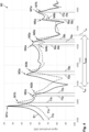
- Fig. 4 shows schematically an amplitude-frequency diagram 80 according to an embodiment.
- the amplitude-frequency diagram 80 is an example of a response or reaction on exciting the pipe-fluid system 10, e.g. by excitation means 40. Note that for determining a physical parameter of a fluid such an amplitude-frequency diagram 80 needs not necessarily be depicted, but only its properties may be used.
- the amplitude-frequency diagram 80 depicts a first curve 81 and a second curve 82.
- the first curve 81 has first maxima M1a - M7a, with respective first frequencies f1a-f7a.
- the second curve 82 (with broken lines) has second maxima M1b - M7b, with respective second frequencies f1b - f7b.
- the first curve 81 is acquired, by the vibration measurement devices 50, as response of a first vibration of the section 14.
- the first curve 81 may have been acquired to get reference values for measurements.
- the second curve 82 is acquiring, by the same vibration measurement devices 50, as response of a second vibration of the section 14.
- the first curve 81 may be acquired, particularly on a regular basis, to get "productive values" of a current situation of the pipe-fluid system 10.
- Fig. 4 shows a computed Eigen-frequency range f target of computed maxima (those maxima are not shown) of the pipe-fluid system 10, within which the frequency correlated to the envisaged physical property is expected.
- the computed Eigen-frequency range f target may be result of a simulation, e.g. of an FEM-simulation, of the pipe-fluid system 10. Due to several frame-conditions, as explained above, the simulation has not a single Eigen-frequency as result, but a frequency range, i.e. an Eigen-frequency range f target .
- the vibration measurement devices 50 After acquiring, by the vibration measurement devices 50, the first maxima M1a - M7a of the first curve 81, the maxima M1a, M2a, M6a, M7a can be excluded from evaluation, because these maxima are outside the computed Eigen-frequency range f target . Hence, a set of first maxima ⁇ M3a, M4a, M5a ⁇ remains. Then, a vibration mode analysis is conducted, e.g. using phase analysis of the at least two vibration measurement devices 50. As a result, it turns out that maxima M4a and M5a have the same phase. This means that M4a and M5a are bending mode maxima and, thus, are also excluded from evaluation. Consequently, a first hoop mode maximum M3a out of the set of first maxima ⁇ M3a, M4a, M5a ⁇ remains or is selected, with a frequency f3a, which can be used as reference frequency.
- second maxima M1a - M7a, of the second curve 82 are acquired. Then, the maxima M1b, M2b, M6b, M7b are excluded from evaluation, because these maxima are out of the computed Eigen-frequency range f target , thus leading to a remaining set of second maxima ⁇ M3b, M4b, M5b ⁇ . From this set of second maxima ⁇ M3b, M4b, M5b ⁇ , second hoop mode maximum M3b is selected, because it turns out - by means of a vibration mode analysis - that M3b is a hoop mode maximum, and the M4b and M5b are bending mode maxima. For deriving the physical parameter of the fluid, a difference between the first hoop mode maximum M3a and the second hoop mode maximum M3b is used.
- Fig. 5a to 5c shows schematically pipe-fluid systems 10 with pipe 20, fluid 30 and at least two vibration measurement devices 50 - depicted as A, B (and, optionally, C)-according to an embodiment.
- two vibration measurement devices A and B are shown, arranged along one line radially circumferential to the pipe 20.
- Fig. 3 or Fig. 6b it becomes clear that this arrangement fits well for detecting phases that indicate hoop mode.
- two vibration measurement devices A and B are shown, arranged at an outer surface of the pipe 20, along one line axially parallel to the pipe 20.
- Fig. 5c two vibration measurement devices A and B are shown, arranged at an outer surface of the pipe 20, along one line axially parallel to the pipe 20.
- Fig. 6a shows schematically a pipe-fluid system 10 with vibration measurement devices 50 (A, B, C) according to an embodiment. Particularly, three vibration measurement devices A, B and C are shown, arranged along one line radially circumferential to the pipe 20.
- Fig. 7 shows a flow diagram 100 depicting a method for determining a physical parameter of a fluid 30 in a section 14 of a pipe-fluid system 10 (see, e.g., Fig. 1 ) according to an embodiment.
- a section 14 of the pipe-fluid system 10 is selected, wherein the section 14 is delimited by a pair of stiff delimiters 11, 19.
- a numerical vibration simulation of the section 14 of the pipe 20 is performed, resulting in a computed Eigen-frequency range f target of computed maxima of the pipe-fluid system 10.
- a step 106 by an excitation means 40, a first vibration of the section 14 is induced.
- a set of first maxima ⁇ M3a, M4a, M5a ⁇ (e.g. using an amplitude-frequency diagram 80, or at least its semantic) is acquired, with a first frequency f3a, f4a, f5a within the Eigen-frequency range f target .
- a first hoop mode maximum M3a out of the set of first maxima ⁇ M3a, M4a, M5a ⁇ is selected.
- a second vibration of the section 14 is induced.
- a set of second maxima ⁇ M3b, M4b, M5b ⁇ is acquired, with a second frequency f3b, f4b, f5b within the Eigen-frequency range f target .
- a second hoop mode maximum M3b out of the set of second maxima ⁇ M3b, M4b, M5b ⁇ is selected.
- the physical parameter of the fluid 30 are derived, from a difference between the first hoop mode maximum M3a and the second hoop mode maximum M3b.
Landscapes
- Physics & Mathematics (AREA)
- General Physics & Mathematics (AREA)
- Immunology (AREA)
- Chemical & Material Sciences (AREA)
- Pathology (AREA)
- General Health & Medical Sciences (AREA)
- Biochemistry (AREA)
- Analytical Chemistry (AREA)
- Health & Medical Sciences (AREA)
- Life Sciences & Earth Sciences (AREA)
- Fluid Mechanics (AREA)
- Engineering & Computer Science (AREA)
- Signal Processing (AREA)
- Acoustics & Sound (AREA)
- Electromagnetism (AREA)
- Mathematical Analysis (AREA)
- Pure & Applied Mathematics (AREA)
- Algebra (AREA)
- Mathematical Physics (AREA)
- Mathematical Optimization (AREA)
- Measuring Volume Flow (AREA)
- Measurement Of Mechanical Vibrations Or Ultrasonic Waves (AREA)
Abstract
performing a numerical vibration simulation of the section (14) of the pipe (20), resulting in a computed Eigen-frequency range (ftarget) of computed maxima of the pipe-fluid system (10);
inducing, by an excitation means (40), a first vibration of the section (14);
acquiring, by at least two vibration measurement devices (50), a set of first maxima (M3a, M4a, M5a) in an amplitude-frequency diagram (80), with a first frequency (f3a, f4a, f5a) within the computed Eigen-frequency range (ftarget);
selecting, by means of a vibration mode analysis, a first hoop mode maximum (M3a) out of the set of first maxima (M3a, M4a, M5a);
inducing, by the excitation means (40), a second vibration of the section (14); acquiring, by the at least two vibration measurement devices (50), a set of second maxima (M3b, M4b, M5b) in the amplitude-frequency diagram (80), with a second frequency (f3b, f4b, f5b) within the computed Eigen-frequency range (ftarget);
selecting, by means of vibration mode analysis, a second hoop mode maximum (M3b) out of the set of second maxima (M3b, M4b, M5b);
deriving the physical parameter of the fluid (30) from a difference between the first hoop mode maximum (M3a) and the second hoop mode maximum (M3b).
Description
- The invention relates to the field of determining a physical parameter of a fluid, particularly in a pipe-fluid system. The invention further relates to a vibration measurement system, to a program element, to a computer-readable storage medium, and to a use.
- Many methods and devices have been developed so far to extract various physical parameters of a process fluid in industrial pipelines by means of a vibration frequency spectrum of the pipe or pipeline. However, it turned out that selecting a best-suited frequency out of the full vibration frequency spectrum is crucial for determining a physical parameter of a fluid with good precision, particularly because not all vibration modes are equally sensitive to any selected physical parameter of the fluid.
- It is an objective of the invention to provide an improved method for determining a physical parameter of a fluid. This objective is achieved by the subject-matter of the independent claims. Further embodiments are evident from the dependent claims and the following description.
- One aspect relates to a method for determining a physical parameter of a fluid in a section of a pipe-fluid system, wherein the pipe-fluid system comprises a pipe configured to be filled with the fluid. The method comprises the steps of:
- selecting the section of the pipe-fluid system, the section being delimited by a pair of stiff delimiters;
- performing a numerical vibration simulation of the section of the pipe, resulting in a computed Eigen-frequency range of computed maxima of the pipe-fluid system; inducing, by an excitation means, a first vibration of the section;
- acquiring, by at least two vibration measurement devices, a set of first maxima in an amplitude-frequency diagram, with a first frequency within the computed Eigen-frequency range;
- selecting, by means of a vibration mode analysis, a first hoop mode maximum out of the set of first maxima;
- inducing, by the excitation means, a second vibration of the section;
- acquiring, by the at least two vibration measurement devices, a set of second maxima in the amplitude-frequency diagram, with a second frequency within the computed Eigen-frequency range;
- selecting, by means of vibration mode analysis, a second hoop mode maximum out of the set of second maxima;
- deriving the physical parameter of the fluid from a difference between the first hoop mode maximum and the second hoop mode maximum.
- The physical parameter of the fluid may be, e.g., pressure, a viscosity and/or a density of the fluid. The fluid may be any material, which can be transported in a pipeline or pipe. Examples may comprise a liquid, a suspension, and/or a gas, for instance a liquefied gas. The pipe-fluid system comprises a pipe that is configured to be filled with said fluid. The pipe may comprise any material, which is able to vibrate as response to a single stimulus. The stimulus may be given by punching with a hammer, any other tool or with a knuckle on the pipe. The tool to be used may comprise a tool with defined force-impact on the pipe. The section of the pipe-fluid system may be a section of the pipe that is delimited by rigid means, such as a clamp or a flange, on each side of the section. The length of the section may be determined by the dimensions of the pipe. Selecting the section of the pipe-fluid system may comprise to build and/or to use a section of the pipe-fluid system that is delimited by a pair of stiff delimiters. The pipe may be filled essentially completely with the fluid in the selected section.
- The numerical vibration simulation of the section of the pipe may comprise an analytical or an FEM-based (Finite Element Method) simulation of the selected section. The vibration simulation of the pipe-fluid system may take into account both physical properties of the pipe and physical properties of the fluid. The vibration simulation may be the simulation of a response to one single stimulus, for example to one single punch with a hammer on the pipe section. The response-frequency or resonant frequency to one single stimulus is often called the Eigen-frequency of the pipe-fluid system. The vibration simulation may result in an amplitude-frequency diagram, i.e. a diagram that shows frequencies of the vibrating section on an x-axis of the diagram and amplitudes on a y-axis of the diagram. Hence, computed maxima in the amplitude-frequency diagram are peaks in the diagram with an amplitude as y-value and a frequency as x-value. The vibration simulation of the pipe-fluid system may result in a computed Eigen-frequency value that may differ, particularly differ between 0 % and 10 %, e.g. between 0 % and 5 %, from the actual Eigen-frequency of the respective real pipe-fluid system. Thus, the computed Eigen-frequency is rather handled as a range, within which the vibration mode correlated to the envisaged fluid property is expected. The "range" may take into account, for example, variations of the fluid, e.g. variations of its pressure, viscosity and/or density, variations of the pipe, e.g. caused by temperature fluctuations, precision deficiencies of the simulation and/or of the section's model and/or further sources of imprecision.
- In other words, for determining a fluid property change from the vibrations of an arbitrary pipe-fluid system with a clamp-on method, the frequency of the vibration mode, which is known to be sensitive to the considered physical property, can be determined by appropriate model calculations. Its accuracy is typically within a range of a few percent of the determined physical property, e.g. within a frequency interval of 5 - 10 %. This prediction may also be used to identify the relevant mode in a real vibration spectrum. However, the actual frequency of any predicted mode typically deviates slightly from the predicted value due to tolerances in dimensions and material data, so that in some cases several frequencies can be found within the predicted frequency interval. Hence, the method disclosed provides a means to select the envisaged vibration mode frequency from a multitude of Eigen-frequencies within the predicted frequency interval, which may result in a correlation between frequency change and fluid property change.
- After the simulation - alternatively parallel to it, or even before it - some "real-world reference values" of the section of the pipe-fluid system may be captured. For this, a first vibration of the section is induced, by an excitation means, e.g. by one punch of a hammer, a solenoid system or other excitation means. The response of the section is acquired by at least two vibration measurement devices. The at least two vibration measurement devices may be arranged in a defined way, particularly to be able to determine vibration modes, i.e. hoop mode or bending mode of a maximum. Particularly, at least two vibration measurement devices (e.g. accelerometers) may be used to discriminate different modes within a pre-defined frequency interval.
- The acquiring may result in a set of first maxima in an amplitude-frequency diagram, with a first frequency within the Eigen-frequency range. The set of first maxima may comprise one maximum only or several maxima; at least for some pipe-fluid systems, the latter may be the regular case. Hence, by limiting the maxima of the full vibration frequency spectrum to only the set of first maxima within the Eigen-frequency range already improves the method for determining a physical parameter of a fluid, by thus selecting a best-suited frequency, or at least only few of them (i.e. the set of first maxima).
- For an even more sophisticated selection of the best-suited frequency, a vibration mode analysis is performed. The vibration mode analysis may differentiate bending mode maxima from hoop mode maxima. Particularly, bending mode maxima have essentially the same amplitude and the same phase measured by the at least two vibration measurement devices. In contrast, hoop mode maxima may have essentially the same amplitude, but a significantly different phase measured by the at least two vibration measurement devices.
- In numerous experiments, it turned out that using a hoop mode maximum is better suited for determining at least some physical parameters of a fluid in a pipe-fluid system, for instance for determining a pressure, a viscosity and/or a density of the fluid. For determining these kind of parameters, the bending mode maxima are discarded and only the first hoop mode maximum, out of the set of first maxima, is used. The first hoop mode maximum may, then, be used as a reference value for the analysis.
- It should be noted that, particularly for other kind of physical parameters - for instance for determining a flow of the fluid -, bending mode maxima may be used instead of the hoop mode maxima. Consequently, in these cases the hoop mode maxima are discarded.
- After these "preparing steps" - which may be performed rarely, in some cases only once - the "productive steps" may be entered, which need to be done to get the at least one physical parameter of the fluid, e.g. on a regular basis.
- For this, a second vibration of the section is induced by the excitation means. Then, as a response, a set of second maxima is acquired by the at least two vibration measurement devices, with a second frequency - of each one of the maxima - within the Eigen-frequency range. From this set of second maxima a second hoop mode maximum is selected, by means of vibration mode analysis. The inducing, the acquiring and the selecting may be done in an analogous way as for capturing the first hoop mode maximum.
- Having the first hoop mode maximum as reference value and the second hoop mode maximum as an indicator of the current state of the section of the pipe-fluid system, the at least one physical parameter of the fluid can be derived from a difference between the first hoop mode maximum and the second hoop mode maximum. Methods for deriving the physical parameter of the fluid and/or for converting the change of the frequency into a change of fluid physical property, are described, e.g., in "Y.C.Fung: On the vibration of Thin Cylindrical Shells", Report No AM 5-8, October 14, 1955. The Ramo-Wooldrige Corporation, Guided Missile Research Division".
- This method improves significantly a non-invasive measurement of at least one physical parameter of a fluid in a pipe-fluid system. Particularly, it improves the selection of the vibration frequency that is to be used for this kind of measurement. Hence, changes of the physical property of the fluid in the pipe can be measured with low effort and high precision. Moreover, besides the physical parameters also local disturbances in the pipe may be measured, and/or alarms may be output, based on situations that may be recognized a critical for the fluid and/or for the pipe.
- In various embodiments, the physical parameter is a pressure, a viscosity and/or a density of the fluid. This enables a continuous monitoring of fluids of the pipe, without a need of opening the pipe or mounting sensors within the pipe.
- In various embodiments, the method comprises following alternative steps:
- selecting, by means of a vibration mode analysis, a first bending mode maximum out of the set of first maxima; and
- selecting, by means of vibration mode analysis, a second bending mode maximum out of the set of second maxima.
- For determining a different kind of physical parameters, for instance for determining a flow of the fluid, these steps may substitute the respective "selecting" steps (which are to select the hoop mode maximum).
- In various embodiments, the fluid is a liquid, a suspension, and/or a gas. Hence, a broad variety of material types can be measured or monitored by this method.
- In various embodiments, the at least two vibration measurement devices are arranged at an outer surface of the pipe, along one line axially parallel to the pipe, and/or along one line radially circumferential to the pipe. The arrangement turned out to be particularly advantageous for both measuring Eigen-frequencies of the pipe-fluid system and for differentiating hoop mode maxima from bending mode maxima.
- In various embodiments, the at least two vibration measurement devices are configured for the vibration mode analysis, particularly for classifying a first or a second maximum acquired, i.e. measured by the vibration measurement devices, either as a bending mode maximum or as a hoop mode maximum.
- Further combinations, e.g. by using three sensors on a circumference of the pipe, may provide further measurement precision, e.g. by eliminating bending mode maxima, and/or by differentiating even and uneven hoop mode numbers ("n-numbers").
- In some embodiments, the vibration mode analysis is achieved by comparing a magnitude (particularly an amplitude or phase of the specific mode in the time domain).
- In various embodiments, the pipe comprises or consists of metal. Pipes of metal or quite widespread and their behaviour is well-known to skilled persons. In addition, many libraries - e.g. software libraries, material data sheets or material property databases - that describe their properties are available. Alternatively, the pipe may comprise or consist of another material that is able to vibrate as response to a single stimulus, e.g. by a hammer or coil system.
- In some embodiments, the pipe has a diameter between 2 cm and 150 cm, and/or has a wall thickness between 2 mm and 50 mm. These are the most widespread embodiments of pipes. However, the method described here may not be limited to these dimensions.
- In some embodiments, the stiff delimiter is designed as a flange or a clamp. Alternatively, the delimiter may be any entity that fixes the pipe at the two ends of the section of interest.
- In various embodiments, the excitation means is designed as a hammer, a solenoid-driven coil, and/or further excitation means. At least some vibration measurement device may be able to measure also vibrations excited by other means, e.g. by knocking with a knuckle, and/or using hammer-type tools of any material.
- In various embodiments, the vibration measurement device is at least one of: an accelerometer, any kind of a microphone, an optical sensor, and/or a strain gauge. The vibration measurement device may be fixed at the pipe, and/or measured from a distance, e.g. by a laser device.
- An aspect relates to a vibration measurement system configured for determining a physical parameter of a fluid in a pipe-fluid system. The vibration measurement system comprises:
- an excitation means, configured for inducing a vibration in a section of the pipe-fluid system;
- at least two vibration measurement devices, configured for acquiring), from the section of the pipe-fluid system, first maxima and second maxima in an amplitude-frequency diagram; and
- an evaluation device, configured for executing at least some of the steps of a method of any one of the preceding claims for determining the physical parameter of the fluid.
- An aspect relates to a computer program product comprising instructions, which, when the program is executed by an evaluation device, cause the computer to carry out the method as described above and/or below.
- An aspect relates to a computer-readable storage medium where a computer program or a computer program product as described above is stored on.
- An aspect relates to a use of a vibration measurement system described above and/or below for determining a physical parameter of a fluid in a pipe-fluid system, particularly for determining a pressure, a viscosity and/or a density of the fluid.
- For further clarification, the invention is described by means of embodiments shown in the figures. These embodiments are to be considered as examples only, but not as limiting.
- The drawings depict:
- Fig. 1
- schematically a vibration measurement system and a pipe-fluid system according to an embodiment;
- Fig. 2a, 2b
- schematically hoop modes of a pipe-fluid system according to an embodiment;
- Fig. 3
- schematically bending modes of a pipe-fluid system according to an embodiment;
- Fig. 4
- schematically an amplitude-frequency diagram according to an embodiment;
- Fig. 5a to 5c
- schematically pipe-fluid systems with vibration measurement devices according to an embodiment;
- Fig. 6a
- schematically a pipe-fluid system with vibration measurement devices according to an embodiment;
- Fig. 6b
- schematically hoop modes of a pipe-fluid system according to an embodiment;
- Fig. 7
- a flow diagram according to an embodiment.
-
Fig. 1 shows schematically avibration measurement system 70 and a pipe-fluid system 10 according to an embodiment. The pipe-fluid system 10 comprises apipe 20 withfluid 30. The fluid 30 may be steady or flow in a direction marked byarrow 35. The pipe-fluid system 10 is delimited by a pair ofdelimiters section 14. - The
vibration measurement system 70 configured for determining a physical parameter of a fluid in the pipe-fluid system 10, particularly insection 14. Thevibration measurement system 70 comprises an excitation means 40, e.g. a hammer. The excitation means 40 may be fixed (not shown) on one of thedelimiters section 14. Additionally, thevibration measurement system 70 comprises at least twovibration measurement devices 50. Thevibration measurement devices 50 may be mounted on an outside of thepipe 20, and/or comprise distant measurement means (not shown), for example a laser sensor. Thevibration measurement devices 50 are configured for acquiring responses of a punch by means of the excitation means 40. The responses may be depicted as an amplitude-frequency diagram; see e.g.Fig. 4 . Further, thevibration measurement system 70 comprises anevaluation device 60. Theevaluation device 60 may control the excitation means 40 and/or thevibration measurement devices 50. Besides, theevaluation device 60 may be configured for executing at least some of the steps of a method as described above and/or below, particularly for determining at least one physical parameter of the fluid 30. -
Figs. 2a and 2b show schematically radial and axial deformation shapes of hoop modes of a vibrating pipe-fluid system 10 (see, e.g.,Fig. 1 ) according to an embodiment.Fig. 2a shows a radial movement shape (cross-section variation) of potential hoop modes, from n=0 to n=4, n being defined by the half the number of vibrational nodes around the circumference, i.e. points which do not move.Fig. 2b shows an axial movement shape (varying amplitude of cross-section variation shown inFig. 3 along the pipe length) of any hoop mode, with m=1 to m=4, m being defined by the number of radial vibration maxima along the system length. (the pipe "blows up" within each m section while vibrating). -
Fig. 3 shows schematically deformations caused by the first two bending modes of a pipe section. The pipe bends longitudinally without changing the cross-section while vibrating. -
Fig. 4 shows schematically an amplitude-frequency diagram 80 according to an embodiment. The amplitude-frequency diagram 80 is an example of a response or reaction on exciting the pipe-fluid system 10, e.g. by excitation means 40. Note that for determining a physical parameter of a fluid such an amplitude-frequency diagram 80 needs not necessarily be depicted, but only its properties may be used. - The amplitude-frequency diagram 80 depicts a
first curve 81 and a second curve 82. Thefirst curve 81 has first maxima M1a - M7a, with respective first frequencies f1a-f7a. The second curve 82 (with broken lines) has second maxima M1b - M7b, with respective second frequencies f1b - f7b. Thefirst curve 81 is acquired, by thevibration measurement devices 50, as response of a first vibration of thesection 14. Thefirst curve 81 may have been acquired to get reference values for measurements. The second curve 82 is acquiring, by the samevibration measurement devices 50, as response of a second vibration of thesection 14. Thefirst curve 81 may be acquired, particularly on a regular basis, to get "productive values" of a current situation of the pipe-fluid system 10. Furthermore,Fig. 4 shows a computed Eigen-frequency range ftarget of computed maxima (those maxima are not shown) of the pipe-fluid system 10, within which the frequency correlated to the envisaged physical property is expected. The computed Eigen-frequency range ftarget may be result of a simulation, e.g. of an FEM-simulation, of the pipe-fluid system 10. Due to several frame-conditions, as explained above, the simulation has not a single Eigen-frequency as result, but a frequency range, i.e. an Eigen-frequency range ftarget. - After acquiring, by the
vibration measurement devices 50, the first maxima M1a - M7a of thefirst curve 81, the maxima M1a, M2a, M6a, M7a can be excluded from evaluation, because these maxima are outside the computed Eigen-frequency range ftarget. Hence, a set of first maxima {M3a, M4a, M5a} remains. Then, a vibration mode analysis is conducted, e.g. using phase analysis of the at least twovibration measurement devices 50. As a result, it turns out that maxima M4a and M5a have the same phase. This means that M4a and M5a are bending mode maxima and, thus, are also excluded from evaluation. Consequently, a first hoop mode maximum M3a out of the set of first maxima {M3a, M4a, M5a} remains or is selected, with a frequency f3a, which can be used as reference frequency. - In the "productive phase", second maxima M1a - M7a, of the second curve 82, are acquired. Then, the maxima M1b, M2b, M6b, M7b are excluded from evaluation, because these maxima are out of the computed Eigen-frequency range ftarget, thus leading to a remaining set of second maxima {M3b, M4b, M5b}. From this set of second maxima {M3b, M4b, M5b}, second hoop mode maximum M3b is selected, because it turns out - by means of a vibration mode analysis - that M3b is a hoop mode maximum, and the M4b and M5b are bending mode maxima. For deriving the physical parameter of the fluid, a difference between the first hoop mode maximum M3a and the second hoop mode maximum M3b is used.
-
Fig. 5a to 5c shows schematically pipe-fluid systems 10 withpipe 20,fluid 30 and at least two vibration measurement devices 50 - depicted as A, B (and, optionally, C)-according to an embodiment. InFig. 5a , two vibration measurement devices A and B are shown, arranged along one line radially circumferential to thepipe 20. Looking atFig. 3 orFig. 6b , it becomes clear that this arrangement fits well for detecting phases that indicate hoop mode. InFig. 5b , two vibration measurement devices A and B are shown, arranged at an outer surface of thepipe 20, along one line axially parallel to thepipe 20. InFig. 5c , two vibration measurement devices A and B are shown, arranged at an outer surface of thepipe 20, along one line axially parallel to thepipe 20. -
Fig. 6a shows schematically a pipe-fluid system 10 with vibration measurement devices 50 (A, B, C) according to an embodiment. Particularly, three vibration measurement devices A, B and C are shown, arranged along one line radially circumferential to thepipe 20. -
Fig. 6b show schematically hoop modes of a pipe-fluid system according to an embodiment, with n=1 to n=4. The phases of the bending modes and the hoop modes are clearly visible inFig. 2 or Fig. 3 , respectively. -
Fig. 7 shows a flow diagram 100 depicting a method for determining a physical parameter of a fluid 30 in asection 14 of a pipe-fluid system 10 (see, e.g.,Fig. 1 ) according to an embodiment. In astep 102, asection 14 of the pipe-fluid system 10 is selected, wherein thesection 14 is delimited by a pair ofstiff delimiters step 104, a numerical vibration simulation of thesection 14 of thepipe 20 is performed, resulting in a computed Eigen-frequency range ftarget of computed maxima of the pipe-fluid system 10. In astep 106, by an excitation means 40, a first vibration of thesection 14 is induced. In astep 108, by at least twovibration measurement devices 50, a set of first maxima {M3a, M4a, M5a} (e.g. using an amplitude-frequency diagram 80, or at least its semantic) is acquired, with a first frequency f3a, f4a, f5a within the Eigen-frequency range ftarget. In astep 110, by means of a vibration mode analysis, a first hoop mode maximum M3a out of the set of first maxima {M3a, M4a, M5a} is selected. In astep 112, by the excitation means 40, a second vibration of thesection 14 is induced. In astep 114, by the at least twovibration measurement devices 50, a set of second maxima {M3b, M4b, M5b} is acquired, with a second frequency f3b, f4b, f5b within the Eigen-frequency range ftarget. In astep 116, by means of vibration mode analysis, a second hoop mode maximum M3b out of the set of second maxima {M3b, M4b, M5b} is selected. In astep 118, the physical parameter of the fluid 30 are derived, from a difference between the first hoop mode maximum M3a and the second hoop mode maximum M3b. -
- 10
- pipe-fluid system
- 11, 19
- delimiters
- 14
- section of the pipe
- 20
- pipe
- 30
- fluid
- 35
- arrow
- 40
- excitation means
- 50, A, B, C
- vibration measurement device
- 60
- evaluation device
- 70
- vibration measurement system
- 80
- amplitude-frequency diagram
- 81
- first curve
- 82
- second curve
- 100
- flow diagram
- 102 - 118
- steps
- M1a - M7a
- first maxima
- M1b - M7b
- second maxima
- f1a - f7a
- first frequency
- f1b - f7b
- second frequency
Claims (15)
- A method for determining a physical parameter of a fluid (30) in a section (14) of a pipe-fluid system (10), wherein the pipe-fluid system (10) comprises a pipe (20) configured to be filled with the fluid (30), the method comprising the steps of:selecting the section (14) of the pipe-fluid system (10), the section (14) being delimited by a pair of stiff delimiters (11, 19);performing a numerical vibration simulation of the section (14) of the pipe (20), resulting in a computed Eigen-frequency range (ftarget) of computed maxima of the pipe-fluid system (10);inducing, by an excitation means (40), a first vibration of the section (14);acquiring, by at least two vibration measurement devices (50), a set of first maxima (M3a, M4a, M5a) in an amplitude-frequency diagram (80), with a first frequency (f3a, f4a) within the computed Eigen-frequency range (ftarget);selecting, by means of a vibration mode analysis, a first hoop mode maximum (M3a) out of the set of first maxima (M3a, M4a, M5a);inducing, by the excitation means (40), a second vibration of the section (14);acquiring, by the at least two vibration measurement devices (50), a set of second maxima (M3b, M4b, M5b) in the amplitude-frequency diagram (80), with a second frequency (f3b, f4b, f5b) within the computed Eigen-frequency range (ftarget);selecting, by means of vibration mode analysis, a second hoop mode maximum (M3b) out of the set of second maxima (M3b, M4b, M5b);deriving the physical parameter of the fluid (30) from a difference between the first hoop mode maximum (M3a) and the second hoop mode maximum (M3b).
- The method of claim 1, comprising the alternative steps of:selecting, by means of a vibration mode analysis, a first bending mode maximum (M4a) out of the set of first maxima (M3a, M4a, M5a); andselecting, by means of vibration mode analysis, a second bending mode maximum (M4b) out of the set of second maxima (M3b, M4b, M5b).
- The method of claim 1 or 2,
wherein the physical parameter is a pressure, a viscosity, and/or a density and/or a flow of the fluid (30). - The method of any one of the preceding claims,
wherein the at least two vibration measurement devices (50) are arranged at an outer surface of the pipe (20), along one line axially parallel to the pipe (20), and/or along one line radially circumferential to the pipe (20). - The method of any one of the preceding claims,wherein the at least two vibration measurement devices (50) are configured for the vibration mode analysis,particularly for classifying a first or second maximum either as a bending mode maximum or as a hoop mode maximum.
- The method of claim 5,
wherein the vibration mode analysis is achieved by comparing an amplitude and/or phase of the vibrations at the Eigen-frequencies within the set of first maxima (M3a, M4a, M5a) and/or within the set of second maxima (M3b, M4b, M5b). - The method of any one of the preceding claims,
wherein the pipe (20) comprises or consists of metal. - The method of any one of the preceding claims,
wherein the pipe (20) has a diameter between 2 cm and 150 cm, and/or has a wall thickness between 2 mm and 50 mm. - The method of any one of the preceding claims,
wherein the stiff delimiter (11, 19) is designed as a flange or a clamp. - The method of any one of the preceding claims,
wherein the excitation means (40) is designed as a hammer, a solenoid-driven coil, and/or further excitation means. - The method of any one of the preceding claims,
wherein the vibration measurement device (50) is at least one of:
an accelerometer, any kind of a microphone, an optical sensor, and/or a strain gauge. - A vibration measurement system (70) configured for determining a physical parameter of a fluid (30) in a pipe-fluid system (10), the vibration measurement system (70) comprising:an excitation means (40), configured for inducing a vibration in a section (14) of the pipe-fluid system (10);at least two vibration measurement devices (50), configured for acquiring), from the section (14) of the pipe-fluid system (10), first maxima (M3a, M4a, M5a) and second maxima (M3b, M4b, M5b) in an amplitude-frequency diagram (80); and an evaluation device (60), configured for executing at least some of the steps of a method of any one of the preceding claims for determining the physical parameter of the fluid (30).
- A computer program product comprising instructions, which, when the program is executed by an evaluation device (60), cause the evaluation device (60) to carry out the method according to any one of claims 1 to 11.
- A computer-readable storage medium where a computer program according to claim 13 is stored on.
- Use of a vibration measurement system (70) according to claim 12 for determining a physical parameter of a fluid (30) in a pipe-fluid system (10), particularly for determining a pressure, a viscosity and/or a density of the fluid (30).
Priority Applications (3)
| Application Number | Priority Date | Filing Date | Title |
|---|---|---|---|
| EP22171523.8A EP4273538B1 (en) | 2022-05-04 | 2022-05-04 | Method for determining a physical parameter of a fluid in a pipe-fluid system |
| CN202310481369.8A CN117007106A (en) | 2022-05-04 | 2023-04-28 | Method for determining a physical parameter of a fluid in a pipeline fluid system |
| US18/308,820 US20230358659A1 (en) | 2022-05-04 | 2023-04-28 | Method for Determining a Physical Parameter of a Fluid in a Pipe-Fluid System |
Applications Claiming Priority (1)
| Application Number | Priority Date | Filing Date | Title |
|---|---|---|---|
| EP22171523.8A EP4273538B1 (en) | 2022-05-04 | 2022-05-04 | Method for determining a physical parameter of a fluid in a pipe-fluid system |
Publications (2)
| Publication Number | Publication Date |
|---|---|
| EP4273538A1 true EP4273538A1 (en) | 2023-11-08 |
| EP4273538B1 EP4273538B1 (en) | 2024-12-25 |
Family
ID=81580070
Family Applications (1)
| Application Number | Title | Priority Date | Filing Date |
|---|---|---|---|
| EP22171523.8A Active EP4273538B1 (en) | 2022-05-04 | 2022-05-04 | Method for determining a physical parameter of a fluid in a pipe-fluid system |
Country Status (3)
| Country | Link |
|---|---|
| US (1) | US20230358659A1 (en) |
| EP (1) | EP4273538B1 (en) |
| CN (1) | CN117007106A (en) |
Families Citing this family (1)
| Publication number | Priority date | Publication date | Assignee | Title |
|---|---|---|---|---|
| CN117871673B (en) * | 2024-01-16 | 2025-09-23 | 西南石油大学 | A method and device for testing the natural frequency of small-sized cylindrical rocks |
Citations (1)
| Publication number | Priority date | Publication date | Assignee | Title |
|---|---|---|---|---|
| US6301973B1 (en) * | 1999-04-30 | 2001-10-16 | The United States Of America As Represented By The Administrator Of The National Aeronautics And Space Administration | Non-intrusive pressure/multipurpose sensor and method |
Family Cites Families (3)
| Publication number | Priority date | Publication date | Assignee | Title |
|---|---|---|---|---|
| US6412354B1 (en) * | 1999-12-16 | 2002-07-02 | Halliburton Energy Services, Inc. | Vibrational forced mode fluid property monitor and method |
| KR101212484B1 (en) * | 2011-10-11 | 2012-12-14 | 주식회사 비앤알테크널러지 | Wireless power charging apparatus and method for mobile |
| JP5495141B2 (en) * | 2012-05-16 | 2014-05-21 | 新日鐵住金株式会社 | Predictive detection method of stick-slip phenomenon, predictive detection device, and cold drawing method of a pipe using the predictive detection method |
-
2022
- 2022-05-04 EP EP22171523.8A patent/EP4273538B1/en active Active
-
2023
- 2023-04-28 US US18/308,820 patent/US20230358659A1/en active Pending
- 2023-04-28 CN CN202310481369.8A patent/CN117007106A/en active Pending
Patent Citations (1)
| Publication number | Priority date | Publication date | Assignee | Title |
|---|---|---|---|---|
| US6301973B1 (en) * | 1999-04-30 | 2001-10-16 | The United States Of America As Represented By The Administrator Of The National Aeronautics And Space Administration | Non-intrusive pressure/multipurpose sensor and method |
Non-Patent Citations (3)
| Title |
|---|
| EL-SINAWI AMEEN H ET AL: "On modeling the dynamics of pipelines: Finite element approach", 2015 6TH INTERNATIONAL CONFERENCE ON MODELING, SIMULATION, AND APPLIED OPTIMIZATION (ICMSAO), IEEE, 27 May 2015 (2015-05-27), pages 1 - 3, XP033170945, DOI: 10.1109/ICMSAO.2015.7152238 * |
| TARANENKO PAVEL ET AL: "Development of a Digital Twin of the Mechanical Part of Coriolis Flowmeters Based on Frequency Response Functions", 2018 GLOBAL SMART INDUSTRY CONFERENCE (GLOSIC), IEEE, 13 November 2018 (2018-11-13), pages 1 - 6, XP033469829, DOI: 10.1109/GLOSIC.2018.8570072 * |
| Y.C.FUNG: "Report No AM 5-8", 14 October 1955, THE RAMO-WOOLDRIGE CORPORATION, article "On the vibration of Thin Cylindrical Shells" |
Also Published As
| Publication number | Publication date |
|---|---|
| CN117007106A (en) | 2023-11-07 |
| EP4273538B1 (en) | 2024-12-25 |
| US20230358659A1 (en) | 2023-11-09 |
Similar Documents
| Publication | Publication Date | Title |
|---|---|---|
| CN115507306B (en) | Methods for monitoring the condition of piping systems for buildup, wear, or corrosion damage. | |
| JP6375948B2 (en) | Defect analysis apparatus, defect analysis method and program | |
| EP2111535B1 (en) | Vibrating wire sensor using spectral analysis | |
| CN101310427B (en) | Stator core looseness diagnosis device and stator core looseness diagnosis method | |
| EP4273538A1 (en) | Method for determining a physical parameter of a fluid in a pipe-fluid system | |
| US11391657B2 (en) | Tubular sensors for inline measurement of the properties of a fluid | |
| WO2010134911A1 (en) | Determining fluid density | |
| US8396676B2 (en) | Method and device for measuring visco-elastic fluid parameters | |
| BR112013004650B1 (en) | apparatus, and method to form a vibrating densitometer | |
| KR20150091136A (en) | Detection of a change in the cross-sectional area of a fluid tube in a vibrating meter by determining a lateral mode stiffness | |
| CN117063056A (en) | Density meter with at least one measuring tube, method of operating a density meter of this type and method of adjusting a density meter of this type | |
| CN110914649A (en) | Measuring sensor for determining the mass flow of a liquid | |
| JP6825714B2 (en) | Vibration judgment device, vibration judgment method and program | |
| Spyrakos et al. | Evaluating structural deterioration using dynamic response characterization | |
| Sun et al. | Investigation of cylindrical resonators’ damping asymmetry via analyzing q factor circumferential distribution | |
| WO2003104845A1 (en) | Method and arrangement for determining sedimentation in a magnetorheological fluid | |
| Ben-Haim | Detecting unknown lateral forces on a bar by vibration measurement | |
| Kocsis | Modeling and vibration analysis of limescale deposition in geothermal pipes | |
| EP1867981A1 (en) | Method of measuring hydrogen concentration in member and device of measuring hydrogen concentration | |
| Manus et al. | Method for Diagnosing Random Zero Shift in Coriolis Flowmeter Caused by its Mechanical Support | |
| Ruan | Signal Procession of Single Measurand for Dynamical System Identification | |
| Golubovic-Bugarski | One approach to correlation between structural damage and dynamic response of the cantilever | |
| JPH06347320A (en) | Identification method for acoustic characteristic in piping system and container | |
| WO2025111603A1 (en) | Hollow cylindrical viscometer employing trapped torsional modes | |
| Budoya et al. | Impedance-Based SHM with High Frequency Excitation Signals of Variable Amplitude and Duration |
Legal Events
| Date | Code | Title | Description |
|---|---|---|---|
| PUAI | Public reference made under article 153(3) epc to a published international application that has entered the european phase |
Free format text: ORIGINAL CODE: 0009012 |
|
| STAA | Information on the status of an ep patent application or granted ep patent |
Free format text: STATUS: THE APPLICATION HAS BEEN PUBLISHED |
|
| AK | Designated contracting states |
Kind code of ref document: A1 Designated state(s): AL AT BE BG CH CY CZ DE DK EE ES FI FR GB GR HR HU IE IS IT LI LT LU LV MC MK MT NL NO PL PT RO RS SE SI SK SM TR |
|
| STAA | Information on the status of an ep patent application or granted ep patent |
Free format text: STATUS: REQUEST FOR EXAMINATION WAS MADE |
|
| 17P | Request for examination filed |
Effective date: 20240416 |
|
| RBV | Designated contracting states (corrected) |
Designated state(s): AL AT BE BG CH CY CZ DE DK EE ES FI FR GB GR HR HU IE IS IT LI LT LU LV MC MK MT NL NO PL PT RO RS SE SI SK SM TR |
|
| GRAP | Despatch of communication of intention to grant a patent |
Free format text: ORIGINAL CODE: EPIDOSNIGR1 |
|
| STAA | Information on the status of an ep patent application or granted ep patent |
Free format text: STATUS: GRANT OF PATENT IS INTENDED |
|
| INTG | Intention to grant announced |
Effective date: 20240814 |
|
| GRAS | Grant fee paid |
Free format text: ORIGINAL CODE: EPIDOSNIGR3 |
|
| GRAA | (expected) grant |
Free format text: ORIGINAL CODE: 0009210 |
|
| STAA | Information on the status of an ep patent application or granted ep patent |
Free format text: STATUS: THE PATENT HAS BEEN GRANTED |
|
| AK | Designated contracting states |
Kind code of ref document: B1 Designated state(s): AL AT BE BG CH CY CZ DE DK EE ES FI FR GB GR HR HU IE IS IT LI LT LU LV MC MK MT NL NO PL PT RO RS SE SI SK SM TR |
|
| REG | Reference to a national code |
Ref country code: GB Ref legal event code: FG4D |
|
| REG | Reference to a national code |
Ref country code: CH Ref legal event code: EP |
|
| REG | Reference to a national code |
Ref country code: DE Ref legal event code: R096 Ref document number: 602022008991 Country of ref document: DE |
|
| REG | Reference to a national code |
Ref country code: IE Ref legal event code: FG4D |
|
| REG | Reference to a national code |
Ref country code: LT Ref legal event code: MG9D |
|
| PG25 | Lapsed in a contracting state [announced via postgrant information from national office to epo] |
Ref country code: HR Free format text: LAPSE BECAUSE OF FAILURE TO SUBMIT A TRANSLATION OF THE DESCRIPTION OR TO PAY THE FEE WITHIN THE PRESCRIBED TIME-LIMIT Effective date: 20241225 |
|
| PG25 | Lapsed in a contracting state [announced via postgrant information from national office to epo] |
Ref country code: FI Free format text: LAPSE BECAUSE OF FAILURE TO SUBMIT A TRANSLATION OF THE DESCRIPTION OR TO PAY THE FEE WITHIN THE PRESCRIBED TIME-LIMIT Effective date: 20241225 |
|
| PG25 | Lapsed in a contracting state [announced via postgrant information from national office to epo] |
Ref country code: BG Free format text: LAPSE BECAUSE OF FAILURE TO SUBMIT A TRANSLATION OF THE DESCRIPTION OR TO PAY THE FEE WITHIN THE PRESCRIBED TIME-LIMIT Effective date: 20241225 |
|
| PG25 | Lapsed in a contracting state [announced via postgrant information from national office to epo] |
Ref country code: NO Free format text: LAPSE BECAUSE OF FAILURE TO SUBMIT A TRANSLATION OF THE DESCRIPTION OR TO PAY THE FEE WITHIN THE PRESCRIBED TIME-LIMIT Effective date: 20250325 |
|
| PG25 | Lapsed in a contracting state [announced via postgrant information from national office to epo] |
Ref country code: LV Free format text: LAPSE BECAUSE OF FAILURE TO SUBMIT A TRANSLATION OF THE DESCRIPTION OR TO PAY THE FEE WITHIN THE PRESCRIBED TIME-LIMIT Effective date: 20241225 Ref country code: GR Free format text: LAPSE BECAUSE OF FAILURE TO SUBMIT A TRANSLATION OF THE DESCRIPTION OR TO PAY THE FEE WITHIN THE PRESCRIBED TIME-LIMIT Effective date: 20250326 |
|
| PG25 | Lapsed in a contracting state [announced via postgrant information from national office to epo] |
Ref country code: RS Free format text: LAPSE BECAUSE OF FAILURE TO SUBMIT A TRANSLATION OF THE DESCRIPTION OR TO PAY THE FEE WITHIN THE PRESCRIBED TIME-LIMIT Effective date: 20250325 |
|
| REG | Reference to a national code |
Ref country code: NL Ref legal event code: MP Effective date: 20241225 |
|
| PG25 | Lapsed in a contracting state [announced via postgrant information from national office to epo] |
Ref country code: NL Free format text: LAPSE BECAUSE OF FAILURE TO SUBMIT A TRANSLATION OF THE DESCRIPTION OR TO PAY THE FEE WITHIN THE PRESCRIBED TIME-LIMIT Effective date: 20241225 |
|
| REG | Reference to a national code |
Ref country code: AT Ref legal event code: MK05 Ref document number: 1754563 Country of ref document: AT Kind code of ref document: T Effective date: 20241225 |
|
| PG25 | Lapsed in a contracting state [announced via postgrant information from national office to epo] |
Ref country code: SM Free format text: LAPSE BECAUSE OF FAILURE TO SUBMIT A TRANSLATION OF THE DESCRIPTION OR TO PAY THE FEE WITHIN THE PRESCRIBED TIME-LIMIT Effective date: 20241225 |
|
| PG25 | Lapsed in a contracting state [announced via postgrant information from national office to epo] |
Ref country code: PL Free format text: LAPSE BECAUSE OF FAILURE TO SUBMIT A TRANSLATION OF THE DESCRIPTION OR TO PAY THE FEE WITHIN THE PRESCRIBED TIME-LIMIT Effective date: 20241225 |
|
| PGFP | Annual fee paid to national office [announced via postgrant information from national office to epo] |
Ref country code: DE Payment date: 20250521 Year of fee payment: 4 |
|
| PG25 | Lapsed in a contracting state [announced via postgrant information from national office to epo] |
Ref country code: ES Free format text: LAPSE BECAUSE OF FAILURE TO SUBMIT A TRANSLATION OF THE DESCRIPTION OR TO PAY THE FEE WITHIN THE PRESCRIBED TIME-LIMIT Effective date: 20241225 |
|
| PG25 | Lapsed in a contracting state [announced via postgrant information from national office to epo] |
Ref country code: IS Free format text: LAPSE BECAUSE OF FAILURE TO SUBMIT A TRANSLATION OF THE DESCRIPTION OR TO PAY THE FEE WITHIN THE PRESCRIBED TIME-LIMIT Effective date: 20250425 |
|
| PG25 | Lapsed in a contracting state [announced via postgrant information from national office to epo] |
Ref country code: PT Free format text: LAPSE BECAUSE OF FAILURE TO SUBMIT A TRANSLATION OF THE DESCRIPTION OR TO PAY THE FEE WITHIN THE PRESCRIBED TIME-LIMIT Effective date: 20250428 |
|
| PG25 | Lapsed in a contracting state [announced via postgrant information from national office to epo] |
Ref country code: EE Free format text: LAPSE BECAUSE OF FAILURE TO SUBMIT A TRANSLATION OF THE DESCRIPTION OR TO PAY THE FEE WITHIN THE PRESCRIBED TIME-LIMIT Effective date: 20241225 |
|
| PG25 | Lapsed in a contracting state [announced via postgrant information from national office to epo] |
Ref country code: RO Free format text: LAPSE BECAUSE OF FAILURE TO SUBMIT A TRANSLATION OF THE DESCRIPTION OR TO PAY THE FEE WITHIN THE PRESCRIBED TIME-LIMIT Effective date: 20241225 Ref country code: AT Free format text: LAPSE BECAUSE OF FAILURE TO SUBMIT A TRANSLATION OF THE DESCRIPTION OR TO PAY THE FEE WITHIN THE PRESCRIBED TIME-LIMIT Effective date: 20241225 |
|
| PG25 | Lapsed in a contracting state [announced via postgrant information from national office to epo] |
Ref country code: SK Free format text: LAPSE BECAUSE OF FAILURE TO SUBMIT A TRANSLATION OF THE DESCRIPTION OR TO PAY THE FEE WITHIN THE PRESCRIBED TIME-LIMIT Effective date: 20241225 |
|
| PG25 | Lapsed in a contracting state [announced via postgrant information from national office to epo] |
Ref country code: CZ Free format text: LAPSE BECAUSE OF FAILURE TO SUBMIT A TRANSLATION OF THE DESCRIPTION OR TO PAY THE FEE WITHIN THE PRESCRIBED TIME-LIMIT Effective date: 20241225 |
|
| PG25 | Lapsed in a contracting state [announced via postgrant information from national office to epo] |
Ref country code: IT Free format text: LAPSE BECAUSE OF FAILURE TO SUBMIT A TRANSLATION OF THE DESCRIPTION OR TO PAY THE FEE WITHIN THE PRESCRIBED TIME-LIMIT Effective date: 20241225 |
|
| PG25 | Lapsed in a contracting state [announced via postgrant information from national office to epo] |
Ref country code: SE Free format text: LAPSE BECAUSE OF FAILURE TO SUBMIT A TRANSLATION OF THE DESCRIPTION OR TO PAY THE FEE WITHIN THE PRESCRIBED TIME-LIMIT Effective date: 20241225 |
|
| REG | Reference to a national code |
Ref country code: DE Ref legal event code: R097 Ref document number: 602022008991 Country of ref document: DE |
|
| PG25 | Lapsed in a contracting state [announced via postgrant information from national office to epo] |
Ref country code: DK Free format text: LAPSE BECAUSE OF FAILURE TO SUBMIT A TRANSLATION OF THE DESCRIPTION OR TO PAY THE FEE WITHIN THE PRESCRIBED TIME-LIMIT Effective date: 20241225 |
|
| PLBE | No opposition filed within time limit |
Free format text: ORIGINAL CODE: 0009261 |
|
| STAA | Information on the status of an ep patent application or granted ep patent |
Free format text: STATUS: NO OPPOSITION FILED WITHIN TIME LIMIT |
|
| REG | Reference to a national code |
Ref country code: CH Ref legal event code: L10 Free format text: ST27 STATUS EVENT CODE: U-0-0-L10-L00 (AS PROVIDED BY THE NATIONAL OFFICE) Effective date: 20251105 |
|
| 26N | No opposition filed |
Effective date: 20250926 |
|
| REG | Reference to a national code |
Ref country code: CH Ref legal event code: H13 Free format text: ST27 STATUS EVENT CODE: U-0-0-H10-H13 (AS PROVIDED BY THE NATIONAL OFFICE) Effective date: 20251223 |
|
| PG25 | Lapsed in a contracting state [announced via postgrant information from national office to epo] |
Ref country code: LU Free format text: LAPSE BECAUSE OF NON-PAYMENT OF DUE FEES Effective date: 20250504 |
|
| PG25 | Lapsed in a contracting state [announced via postgrant information from national office to epo] |
Ref country code: CH Free format text: LAPSE BECAUSE OF NON-PAYMENT OF DUE FEES Effective date: 20250531 |
|
| REG | Reference to a national code |
Ref country code: BE Ref legal event code: MM Effective date: 20250531 |
|
| PG25 | Lapsed in a contracting state [announced via postgrant information from national office to epo] |
Ref country code: MC Free format text: LAPSE BECAUSE OF FAILURE TO SUBMIT A TRANSLATION OF THE DESCRIPTION OR TO PAY THE FEE WITHIN THE PRESCRIBED TIME-LIMIT Effective date: 20241225 |
|
| PG25 | Lapsed in a contracting state [announced via postgrant information from national office to epo] |
Ref country code: IE Free format text: LAPSE BECAUSE OF NON-PAYMENT OF DUE FEES Effective date: 20250504 |
|
| PG25 | Lapsed in a contracting state [announced via postgrant information from national office to epo] |
Ref country code: BE Free format text: LAPSE BECAUSE OF NON-PAYMENT OF DUE FEES Effective date: 20250531 |
|
| PG25 | Lapsed in a contracting state [announced via postgrant information from national office to epo] |
Ref country code: FR Free format text: LAPSE BECAUSE OF NON-PAYMENT OF DUE FEES Effective date: 20250531 |