EP4273519A1 - A tool for use during calibration of a sensor - Google Patents
A tool for use during calibration of a sensor Download PDFInfo
- Publication number
- EP4273519A1 EP4273519A1 EP22171933.9A EP22171933A EP4273519A1 EP 4273519 A1 EP4273519 A1 EP 4273519A1 EP 22171933 A EP22171933 A EP 22171933A EP 4273519 A1 EP4273519 A1 EP 4273519A1
- Authority
- EP
- European Patent Office
- Prior art keywords
- tool according
- tool
- contact surface
- lever
- parts
- Prior art date
- Legal status (The legal status is an assumption and is not a legal conclusion. Google has not performed a legal analysis and makes no representation as to the accuracy of the status listed.)
- Granted
Links
Images

Classifications
-
- G—PHYSICS
- G01—MEASURING; TESTING
- G01G—WEIGHING
- G01G19/00—Weighing apparatus or methods adapted for special purposes not provided for in the preceding groups
- G01G19/08—Weighing apparatus or methods adapted for special purposes not provided for in the preceding groups for incorporation in vehicles
-
- G—PHYSICS
- G01—MEASURING; TESTING
- G01G—WEIGHING
- G01G23/00—Auxiliary devices for weighing apparatus
- G01G23/01—Testing or calibrating of weighing apparatus
-
- G—PHYSICS
- G01—MEASURING; TESTING
- G01L—MEASURING FORCE, STRESS, TORQUE, WORK, MECHANICAL POWER, MECHANICAL EFFICIENCY, OR FLUID PRESSURE
- G01L25/00—Testing or calibrating of apparatus for measuring force, torque, work, mechanical power, or mechanical efficiency
Definitions
- the disclosure relates to a tool for calibration of load sensors, such as for calibration of load sensors used in vehicles.
- the disclosure can be applied for calibration of load sensors in heavy-duty vehicles, such as trucks, buses, and construction equipment.
- the disclosure can be applied in connection with load sensors designed for measuring axle and cargo load in vehicles with leaf spring suspension.
- the disclosure is also applicable for calibration of load sensors in non-vehicle applications.
- a load sensor also commonly referred to as a load cell, is commonly used for measuring axle and/or cargo loads in vehicles, and for determining the weight of objects in various applications.
- the load sensor is an electronic device that measures resistance and/or deformation within the sensor to determine tension and/or compression forces.
- a common type of load sensor includes an electronic sensing unit fixed to a structure, such as to a vehicle frame, and a moveable lever connecting the electronic sensing unit to an axle of the vehicle. Depending on a weight of the vehicle load, the vehicle frame will move with respect to the axle and thereby the lever will move.
- the electronic sensing unit detects the distance between the vehicle frame and the axle and generates an output signal from which the applied load can be determined.
- the lever To calibrate certain types of load sensors, the lever needs to be kept in a fixed position corresponding to a position of a predetermined load, e.g., zero load, while an electronic calibration process is carried out.
- a special tool may be used for this purpose, being designed to hold the lever in a desired fixed position with respect to the vehicle frame, i.e., at a predetermined calibration distance.
- the calibration distance may vary depending on vehicle configuration, requiring a specific tool for each vehicle configuration.
- An object of the disclosure is to provide an improved tool for calibration of load sensors, such as load sensors designed for measuring axle and/or cargo loads in vehicles (e.g., with leaf spring suspension).
- a tool for use in connection with calibration of a load sensor comprises:
- the tool is used to hold the lever in a fixed position corresponding to a position of a predetermined load, e.g., zero load, during the calibration of the sensor.
- a predetermined load e.g., zero load
- the tool enables calibration of load sensors with at least two different calibration distances corresponding to the predefined axial distances between the first contact surface and the second contact surface.
- the appropriate axial position is selected depending on the calibration distance of the sensor prior to using the tool, i.e., prior to engaging the tool with the lever and the structure.
- a more versatile tool is provided that may be used in different calibration scenarios. Since the parts are irremovable from one another, there is no risk of dropping or displacing one of the parts.
- the tool is particularly useful during calibration of load sensors in vehicles, such as load sensors used to determine the weight of goods loaded on the vehicle, for example a leaf spring suspension load sensor.
- the load sensor may be of any type relying on a moveable lever exerting a force on an electronic sensing unit of the load sensor to determine the load, such as a load cell.
- the lever may at one end be rigidly connected to a rotatable part of the electronic sensing unit, in turn fixed to the structure, such as a vehicle chassis or vehicle frame.
- the lever may at a second end be rotatably connected to another structure, such as a vehicle axle.
- the lever When the structure, such as the vehicle frame, moves with respect to the other structure, such as the vehicle axle, the lever will rotate and thereby induce a movement of the rotatable part of the electronic sensing unit.
- the electronic sensing unit may thus detect an applied load as a function of the lever position.
- the tool disclosed herein may be used to hold the lever in a correct position representing a predetermined load, such as zero load, during an electronic calibration process of the electronic sensing unit.
- the tool according to the disclosure may advantageously be manufactured by additive manufacturing, wherein the first and second parts may be assembled together as they are formed.
- the tool may thereby be formed without welding interfaces, screws, etc.
- the first and second parts such that no support structure is needed during the additive manufacturing, the tool is ready to use right after the additive manufacturing process.
- the first and second parts may be built simultaneously in the additive manufacturing process and thus be entangled and irremovable from one another once the additive manufacturing process is completed.
- the axis referred to herein may be a common longitudinal axis of the tool, along which the first and second parts extend.
- the first and second parts are selectively lockable relative to one another in the at least two predefined axial positions by rotation of the second part relative to the first part around the axis to an interlocking position in which axial movement of the second part relative to the first part is prevented.
- the first and second parts are selectively moveable between the predefined axial positions by rotation of the second part relative to the first part around the axis to a moveable position in which axial movement of the second part relative to the first part is allowed. This allows intuitive adjustment of the calibration distance.
- the at least two predefined axial positions are defined by at least one protrusion formed on one of the first and second parts, and at least two axially separated circumferential grooves formed in the other one of the first and second parts, wherein the at least one protrusion is configured to selectively engage the circumferential grooves.
- Such a configuration with grooves and protrusion(s) may be formed during an additive manufacturing process, removing the need for machining after forming of the parts.
- the grooves and protrusion(s) may also serve to make the second part irremovable from the first part.
- a larger number of circumferential grooves may be provided to increase the number of predefined axial positions.
- the at least two circumferential grooves are connected by at least one connecting groove, wherein the at least one protrusion is configured to selectively engage the at least one connecting groove to move the second part between the at least two predefined axial positions.
- the at least one connecting groove may advantageously extend in the axial direction, although a helical extension may also be envisaged.
- the at least one protrusion comprises at least two protrusions distributed around a circumference of the part, the at least two protrusions being configured for simultaneous engagement with the same circumferential groove.
- the at least one protrusion is formed on the second part, and the circumferential grooves are formed in the first part.
- the at least one protrusion may thus be formed on an outer surface of the second part, while as the circumferential grooves are formed in an inner surface of the first part.
- the opposite configuration is also possible.
- the first part comprises an axially extending channel in which the second part is moveably received and from which the second part extends.
- the axially extending channel may be in the form of a through-hole, thereby reducing the weight of the tool.
- the tool may be arranged in a telescope configuration.
- the first part comprises a handle, facilitating handling of the tool.
- the handle may comprise recesses providing a structured gripping surface.
- the recesses provide friction and may also reduce the overall weight of the tool by reducing the amount of material needed.
- the first engagement member comprises a radially extending base and two axially extending arms extending from the base, the two axially extending arms and the radially extending base forming a U-shaped slot for receiving the lever of the load sensor, the radially extending base defining the first contact surface.
- the radial extension is herein defined with respect to the axis, i.e., the radial extension is transverse to the axis.
- the U-shaped slot may be radially offset from a main portion of the first part, wherein the main portion extends along the axis and comprises the axially extending channel referred to above. It may also be located at an axial distance from the main portion.
- the U-shaped slot is configured to receive and fix the moveable lever of the load sensor with respect to the structure when the second engagement member is in engagement with the structure. The U-shaped slot ensures that the lever is securely held in place during the calibration process.
- the second part comprises a rod and a circumferential shoulder extending radially outward from the rod, the circumferential shoulder defining the second contact surface to abut the structure when an end portion of the rod is received in an opening defined in the structure.
- the second engagement member is formed by the circumferential shoulder and the end portion of the rod. The end portion of the rod may be dimensioned to fit tightly within the opening.
- each one of the first and second parts is formed by material layers, which material layers are stacked onto one another along the axis.
- the material layers may advantageously be formed by additive manufacturing.
- the tool may thus be produced by additive manufacturing, providing a light-weight tool in which the first and second parts may be assembled together already during forming of the respective parts. Furthermore, weak points in the form of welding interfaces and similar can be avoided, thus providing a strong tool.
- the first and second parts are made of the same material.
- the production process is thereby simplified in comparison with prior art tools having parts of different materials.
- the material may be a metal material, such as a steel alloy, an aluminium based alloy, or a titanium-based alloy.
- suitable alloys may be AISi10Mg, 316L steel, maraging steel, and Ti6Al4V.
- a high-performance polymer material may be used. These materials are all possible to use in an additive manufacturing process to provide a strong, yet light-weight tool.
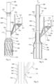
- a tool 100 according to a first embodiment of the disclosure is schematically illustrated in fig. 1 .
- the tool 100 is herein shown during installation for its use in connection with calibration of a load sensor 200 of a vehicle (not shown) having a vehicle frame and a suspended vehicle axle.
- the load sensor 200 comprises an electronic sensing unit 205 and a lever 210, which is at a first end 211 fixed to a rotatable portion of the electronic sensing unit 205 by a nut 206.
- the electronic sensing unit 205 is in turn attached to a structure 300, such as the vehicle frame, such that the lever 200 is moveably attached to the structure 300.
- the lever 210 is configured to be attached to the vehicle axle by a rigid cable, rod, or similar.
- a ball coupling 207 is provided for this purpose, such that the lever is able to rotate relatively the vehicle axle.
- a tension spring 310 is provided, which is in fig. 1 shown in a relaxed state but which is to be connected between the vehicle frame and the vehicle axle so as to be tensed when a load is applied to the vehicle frame and the lever 210 is moved with respect thereto, i.e., rotated with respect to the structure 300.
- the electronic sensing unit 205 When the load sensor 200 is in use, the electronic sensing unit 205 will, from a rotational position of the lever 210, detect a vertical distance that the vehicle frame is displaced relatively the vehicle axle as a load is applied to the vehicle frame, from which the load may be determined. When the load is applied, the structure 300 carrying the electronic sensing unit 205 will be pressed downwards. The lever 210 is thus moveable with respect to the structure 300 when a load is applied. The electronic sensing unit 205 generates an output signal from which the applied load can be determined.
- the lever 210 During calibration of the load sensor 200, the lever 210 must be kept in a fixed position with respect to the structure 300 to establish a position corresponding to zero load. When the zero-load position has been established, a calibration process of the electronic sensing unit 205 is initiated.
- the fixed position is achieved by using the tool 100.
- the tool 100 comprises a first part 110 and a second part 150, both having a main extension along a common longitudinal axis A.
- the first part 110 comprises a first engagement member 111 having a first contact surface (shown in fig. 2 ) for contacting the lever 210 of the load sensor 200.
- the first engagement member 111 herein has a U-shaped slot 122 for receiving the second end 212 of the lever 210.
- the first engagement member 111 engages the lever 210 between the ball coupling 207 and the nut 206.
- the second part 150 comprises a rod 154 and a second engagement member 151.
- the second engagement member 151 has a second contact surface (shown in fig. 2 ) for engaging the structure 300, thereby ensuring that the lever is in a fixed position and predefined position with respect to the structure 300.
- the second engagement member 151 comprises a circumferential shoulder 157 configured to contact a surface 303 of the structure 300 surrounding an opening 301.
- the second engagement member 151 further comprises an end portion 155 of the rod 154, which is configured to be inserted into the opening 301 when the first engagement member 111 is engaged with the lever 210.
- the second part 150 is irremovable from the first part 110 and is further moveable relative to the first part 110 along the axis A between at least two selectively lockable predefined axial positions.
- Each predefined axial position provides a predefined axial distance d, as illustrated in fig. 4 for a second embodiment of the tool 100, i.e., as measured along the axis A, between the first contact surface and the second contact surface.
- the tool 100 Prior to engaging the tool 100 with the structure 300 and the lever 210, the tool 100 is adjusted to select an appropriate axial distance d corresponding to the calibration distance of the sensor 200 in the specific application.
- the tool 100 comprises a first part 110 and a second part 150, both having a main extension along a common longitudinal axis A.
- the first part 110 comprises a first engagement member 111 having a first contact surface 114 for contacting the lever 210 of the load sensor 200.
- It further comprises a second part 150 comprising a second engagement member 151.
- the second engagement member 151 has a second contact surface 152 for engaging the structure 300.
- the second part 150 is moveable relative to the first part 110 along the axis A between at least two selectively lockable predefined axial positions, herein three predefined axial positions. Each predefined axial position provides a predefined axial distance d between the first contact surface 114 and the second contact surface 152.
- the second part 150 is irremovable from the first part 110.
- the second engagement member 151 is further provided at a fixed radial distance from the first engagement member 111.
- the first part 110 has in the illustrated embodiments a tubular main portion 130 extending from a first end 115 to a second end 116, with a wider portion comprising a handle 120 adjacent to the first end 115, and a narrower neck portion 117 adjacent to the second end 116, with a truncated cone portion 131 connecting the handle 120 to the neck portion 117.
- the first engagement member 111 is radially offset from the tubular main portion 130 and is attached to the neck portion 117 by a support arrangement 118.
- An axially extending channel 119 (see fig. 6 ) is provided within the tubular main portion 130 of the first part 110.
- the first engagement member 111 comprises a radially extending base 114 defining the first contact surface 114. It further comprises first and second axially extending arms 112, 113 extending from the base 114, away from the first end 115 of the tubular main portion 130 of the first part 110.
- the two axially extending arms 112, 113 and the radially extending base form a U-shaped slot 122 for receiving the lever 210 of the load sensor 200 and fix it with respect to the structure 300 during the calibration process.
- the tool 100 on the one hand fixes a rotational position of the lever 210, and thereby of the rotatable part of the electronic sensing unit 205, and on the other hand holds the lever 210 at a fixed distance from the surface 301 of the structure 300.
- the second arm 113 is provided at a shorter radial distance from the axis A than the first arm 112 and is in the second embodiment wider and longer than the first arm 112, although the latter is not necessary.
- the second arm 113 comprises in the second embodiment a curved surface 113a with a radius of curvature centred on the axis A, although it may instead comprise a surface with a different curvature or a flat surface.
- the second part 150 comprises a rod 154.
- the rod 154 is a hollow rod extending between a first end 156 located within the axially extending channel 119 and a second end 158.
- the rod 154 is hence moveably received in the axially extending channel 119 and extends axially from the second end 116 of the tubular main portion 130 of the first part 110.
- the second engagement member 151 comprises a circumferential shoulder 157 extending radially outward from and around the rod 154.
- the circumferential shoulder 157 delimits an end portion 155 of the rod 154, extending between the circumferential shoulder 157 and the second end 158.
- the circumferential shoulder 157 defines the second contact surface 152, which extends in a radial plane and is arranged to abut the structure 300 when the end portion 155 of the rod 154 is received in an opening 301 defined in the structure 300.
- the three predefined axial positions are in the second embodiment defined by three axially separated and identical circumferential grooves 131, 132, 133 formed in the neck portion 117 of the first part 110, and a protrusion 161 formed on the second part 150.
- the second part 150 is in a first axial position in which the protrusion 161 is in engagement with a first one 131 of the circumferential grooves 131, 132, 133.
- the protrusion 161 is dimensioned to be slidable along the groove 131, i.e., the second part 150 is in the first axial position rotatable relative to the first part 110 around the axis A.
- the second part 150 is further moveable from the first axial position defined by the first circumferential groove 131 to a second axial position defined by a second one 132 of the circumferential grooves 131, 132, 133 via a connecting groove 134 as illustrated in fig. 6 .
- the connecting groove 134 extends in the axial direction from the first circumferential groove 131 to a third one 133 of the circumferential grooves 131, 132, 133.
- the connecting groove 134 has the same depth as the circumferential grooves 131, 132, 133 and allows the protrusion 161 to slide therein when moving the second part 150 in the axial direction relative to the first part 110.
- more than one protrusion 161 is provided, more than one connecting groove 134 must likewise be provided, so that each protrusion may slide in a corresponding connecting groove.
- the first and second parts 110, 150 are selectively lockable relative to one another in the three predefined axial positions defined by the circumferential grooves 131, 132, 133. This is achieved by rotation of the second part 150 relative to the first part 110 around the axis A such that the protrusion 161 is moved along one of the circumferential grooves 131, 132, 133, away from the connecting groove 134 and to an interlocking position in which axial movement of the second part 150 relative to the first part 110 is prevented.
- several separate tools with unique calibration distances may be consolidated into one tool 100 with parts 110, 150 moveable to each of those unique calibration distances.
- circumferential grooves 131, 132, 133 extend around an entire inner circumference of the neck portion 117, i.e., that the circumferential grooves 131, 132, 133 are annular. It is sufficient that the circumferential grooves 131, 132, 133 are long enough to provide interlocking positions in which the protrusion 161 is unable to slide into the connecting groove 134.
- the support arrangement 118 is in the second embodiment formed by two beams 118a, 118b extending from the neck portion 117 to the first arm 112 and the second arm 113 of the first engagement member 111, respectively.
- the two beams 118a, 118b extend at an angle with respect to the axis A.
- a plurality of strengthening bars connect the first arm 118a to the base 114.
- the support arrangement 118 may be configured as a framework structure, such as a truss, implying a robust and light-weight configuration.
- angles and dimensions of the support arrangement 118 may be set so as to enable additive manufacturing of the tool 100 without the use of support structures that must be removed after building the tool 100.
- the handle 120 comprises in the second embodiment a plurality of recesses 121 providing a structured gripping surface.
- the recesses 121 further reduce the amount of material needed for forming the tool 100.
- the recesses 121 are illustrated as elongated recesses having a helical extension, but there are of course many alternative surface structures that may be used to enhance friction and save weight in comparison with a non-patterned handle.
- the tool 100 may advantageously be manufactured using additive manufacturing, i.e., it is formed by material layers, which material layers are stacked onto one another along the axis A such that the first part 110 and the second part 150 are formed simultaneously.
- additive manufacturing i.e., it is formed by material layers, which material layers are stacked onto one another along the axis A such that the first part 110 and the second part 150 are formed simultaneously.
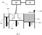
- Such a manufacturing process using a 3D printing tool 1 is schematically illustrated in fig. 8 .
- Fig. 8 is a simplified cross-section view of an example 3D printing machine 800, which may be used to manufacture the tool 100 by Selective Laser Melting (SLM) process.
- SLM Selective Laser Melting
- a product 880 is formed by selectively melting successive layers of powder by the interaction of a laser beam.
- the powder material is heated and, if sufficient power is applied, melts and forms a liquid pool. Afterwards, the molten pool solidifies and cools down quickly, and the consolidated material starts to form the product.
- the building platform is lowered by an amount equal to the layer thickness and a new layer of powder is deposited. This process is repeated until the product is completed.
- This layer-by-layer process is able to net-shape manufacture complex structures from a computer-aided design (CAD) model and a wide range of materials without the need of expensive tooling and machining so that the delay between design and manufacture is minimised.
- CAD computer-aided design
- metal powder 810 in a dispenser plate 820 is heated close to its melting point and spread by a powder recoater 830 on a building plate 840.
- a scanning head 850 connected to a laser generator 860 draws or scans a cross section of a part 880, e.g., the tool 100, into the powder material.
- the cross sections of the first end 115 of the first part 110 and the first end 156 of the second part 150 are formed by the laser beam.
- the building plate 640 is lowered corresponding to one layer thickness, which may be approximately 0.1 mm, after which the process is repeated until the tool 100 is completed when reaching the second end 158 of the second part 150.
- a collecting plate 670 is used for collecting the rest of un-melted metal powder.
- the tool 100 may be produced without any support structures for supporting overhanging features during the additive manufacturing process.
- the angle ⁇ between any overhanging feature of the tool 100 and a radial plane R of the tool 100 should preferably be above a threshold, such as at least 10°, or at least 20°, or at least 30°, as indicated in fig. 5 .
- the tool 100 produced using additive manufacturing does not comprise any weak points such as welding joints or similar.
- the tool 100 may, as in the second embodiment, be designed such that the amount of material needed is as small as possible. This is in the second embodiment achieved by, e.g., the recesses 121 of the handle 120, open spaces between the beams 118a, 118b and the strengthening bars of the support structure 118, the hollow second part 150, and recesses formed in the circumferential shoulder 157.
Landscapes
- Physics & Mathematics (AREA)
- General Physics & Mathematics (AREA)
- Mutual Connection Of Rods And Tubes (AREA)
- Force Measurement Appropriate To Specific Purposes (AREA)
Abstract
Description
- The disclosure relates to a tool for calibration of load sensors, such as for calibration of load sensors used in vehicles.
- The disclosure can be applied for calibration of load sensors in heavy-duty vehicles, such as trucks, buses, and construction equipment. In particular, the disclosure can be applied in connection with load sensors designed for measuring axle and cargo load in vehicles with leaf spring suspension. The disclosure is also applicable for calibration of load sensors in non-vehicle applications.
- A load sensor, also commonly referred to as a load cell, is commonly used for measuring axle and/or cargo loads in vehicles, and for determining the weight of objects in various applications. The load sensor is an electronic device that measures resistance and/or deformation within the sensor to determine tension and/or compression forces.
- A common type of load sensor includes an electronic sensing unit fixed to a structure, such as to a vehicle frame, and a moveable lever connecting the electronic sensing unit to an axle of the vehicle. Depending on a weight of the vehicle load, the vehicle frame will move with respect to the axle and thereby the lever will move. The electronic sensing unit detects the distance between the vehicle frame and the axle and generates an output signal from which the applied load can be determined.
- To calibrate certain types of load sensors, the lever needs to be kept in a fixed position corresponding to a position of a predetermined load, e.g., zero load, while an electronic calibration process is carried out. A special tool may be used for this purpose, being designed to hold the lever in a desired fixed position with respect to the vehicle frame, i.e., at a predetermined calibration distance. However, the calibration distance may vary depending on vehicle configuration, requiring a specific tool for each vehicle configuration.
- An object of the disclosure is to provide an improved tool for calibration of load sensors, such as load sensors designed for measuring axle and/or cargo loads in vehicles (e.g., with leaf spring suspension).
- The object is achieved by a tool according to claim 1. Hence, a tool for use in connection with calibration of a load sensor is provided. The tool comprises:
- a first part comprising a first engagement member having a first contact surface to contact a lever of a load sensor, the lever being moveably mounted to a structure;
- a second part comprising a second engagement member having a second contact surface to engage the structure, the second part being irremovable from the first part;
- wherein the second part is moveable relative to the first part along an axis between at least two selectively lockable predefined axial positions, each predefined axial position providing a predefined axial distance between the first contact surface and the second contact surface.
- The tool is used to hold the lever in a fixed position corresponding to a position of a predetermined load, e.g., zero load, during the calibration of the sensor. By providing a tool having a second part which is moveable with respect to a first part between two or more predefined axial positions, the tool enables calibration of load sensors with at least two different calibration distances corresponding to the predefined axial distances between the first contact surface and the second contact surface. The appropriate axial position is selected depending on the calibration distance of the sensor prior to using the tool, i.e., prior to engaging the tool with the lever and the structure. Thus, a more versatile tool is provided that may be used in different calibration scenarios. Since the parts are irremovable from one another, there is no risk of dropping or displacing one of the parts.
- The tool is particularly useful during calibration of load sensors in vehicles, such as load sensors used to determine the weight of goods loaded on the vehicle, for example a leaf spring suspension load sensor. The load sensor may be of any type relying on a moveable lever exerting a force on an electronic sensing unit of the load sensor to determine the load, such as a load cell. The lever may at one end be rigidly connected to a rotatable part of the electronic sensing unit, in turn fixed to the structure, such as a vehicle chassis or vehicle frame. The lever may at a second end be rotatably connected to another structure, such as a vehicle axle. When the structure, such as the vehicle frame, moves with respect to the other structure, such as the vehicle axle, the lever will rotate and thereby induce a movement of the rotatable part of the electronic sensing unit. The electronic sensing unit may thus detect an applied load as a function of the lever position. The tool disclosed herein may be used to hold the lever in a correct position representing a predetermined load, such as zero load, during an electronic calibration process of the electronic sensing unit.
- The tool according to the disclosure may advantageously be manufactured by additive manufacturing, wherein the first and second parts may be assembled together as they are formed. The tool may thereby be formed without welding interfaces, screws, etc. Furthermore, by designing the first and second parts such that no support structure is needed during the additive manufacturing, the tool is ready to use right after the additive manufacturing process. The first and second parts may be built simultaneously in the additive manufacturing process and thus be entangled and irremovable from one another once the additive manufacturing process is completed.
- The axis referred to herein may be a common longitudinal axis of the tool, along which the first and second parts extend.
- Optionally, the first and second parts are selectively lockable relative to one another in the at least two predefined axial positions by rotation of the second part relative to the first part around the axis to an interlocking position in which axial movement of the second part relative to the first part is prevented.
- Optionally, the first and second parts are selectively moveable between the predefined axial positions by rotation of the second part relative to the first part around the axis to a moveable position in which axial movement of the second part relative to the first part is allowed. This allows intuitive adjustment of the calibration distance.
- Optionally, the at least two predefined axial positions are defined by at least one protrusion formed on one of the first and second parts, and at least two axially separated circumferential grooves formed in the other one of the first and second parts, wherein the at least one protrusion is configured to selectively engage the circumferential grooves. Such a configuration with grooves and protrusion(s) may be formed during an additive manufacturing process, removing the need for machining after forming of the parts. The grooves and protrusion(s) may also serve to make the second part irremovable from the first part. A larger number of circumferential grooves may be provided to increase the number of predefined axial positions.
- Optionally, the at least two circumferential grooves are connected by at least one connecting groove, wherein the at least one protrusion is configured to selectively engage the at least one connecting groove to move the second part between the at least two predefined axial positions. The at least one connecting groove may advantageously extend in the axial direction, although a helical extension may also be envisaged.
- Optionally, the at least one protrusion comprises at least two protrusions distributed around a circumference of the part, the at least two protrusions being configured for simultaneous engagement with the same circumferential groove. By using two or three protrusions distributed around the circumference of the part, an improved stability in the predefined axial positions may be achieved.
- Optionally, the at least one protrusion is formed on the second part, and the circumferential grooves are formed in the first part. The at least one protrusion may thus be formed on an outer surface of the second part, while as the circumferential grooves are formed in an inner surface of the first part. However, the opposite configuration is also possible.
- Optionally, the first part comprises an axially extending channel in which the second part is moveably received and from which the second part extends. The axially extending channel may be in the form of a through-hole, thereby reducing the weight of the tool. Thus, according to an example embodiment, the tool may be arranged in a telescope configuration.
- Optionally, the first part comprises a handle, facilitating handling of the tool. The handle may comprise recesses providing a structured gripping surface. The recesses provide friction and may also reduce the overall weight of the tool by reducing the amount of material needed.
- Optionally, the first engagement member comprises a radially extending base and two axially extending arms extending from the base, the two axially extending arms and the radially extending base forming a U-shaped slot for receiving the lever of the load sensor, the radially extending base defining the first contact surface. The radial extension is herein defined with respect to the axis, i.e., the radial extension is transverse to the axis. The U-shaped slot may be radially offset from a main portion of the first part, wherein the main portion extends along the axis and comprises the axially extending channel referred to above. It may also be located at an axial distance from the main portion. The U-shaped slot is configured to receive and fix the moveable lever of the load sensor with respect to the structure when the second engagement member is in engagement with the structure. The U-shaped slot ensures that the lever is securely held in place during the calibration process.
- Optionally, the second part comprises a rod and a circumferential shoulder extending radially outward from the rod, the circumferential shoulder defining the second contact surface to abut the structure when an end portion of the rod is received in an opening defined in the structure. Thus, the second engagement member is formed by the circumferential shoulder and the end portion of the rod. The end portion of the rod may be dimensioned to fit tightly within the opening.
- Optionally, each one of the first and second parts is formed by material layers, which material layers are stacked onto one another along the axis. The material layers may advantageously be formed by additive manufacturing. The tool may thus be produced by additive manufacturing, providing a light-weight tool in which the first and second parts may be assembled together already during forming of the respective parts. Furthermore, weak points in the form of welding interfaces and similar can be avoided, thus providing a strong tool.
- Optionally, the first and second parts are made of the same material. The production process is thereby simplified in comparison with prior art tools having parts of different materials.
- Optionally, the material may be a metal material, such as a steel alloy, an aluminium based alloy, or a titanium-based alloy. By way of example only, suitable alloys may be AISi10Mg, 316L steel, maraging steel, and Ti6Al4V. Instead of a metal material, a high-performance polymer material may be used. These materials are all possible to use in an additive manufacturing process to provide a strong, yet light-weight tool.
- Further advantages and advantageous features of the disclosure are disclosed in the following description and in the dependent claims.
- With reference to the appended drawings, below follows a more detailed description of embodiments of the disclosure cited as examples.
- In the drawings:
- Fig. 1
- shows a perspective view of a tool according to an embodiment in connection with calibration of a load sensor,
- Fig. 2
- is a perspective view of a tool according to another embodiment of the disclosure,
- Fig. 3
- is a side view of the tool shown in
fig. 2 , - Fig. 4
- is a sectional view of the tool shown in
fig. 2 , - Fig. 5
- is a magnification of the dash-dotted area in
fig. 4 , - Fig. 6
- is a sectional perspective view of a portion of the tool shown in
fig. 2 , - Fig. 7
- is a partially sectional perspective view of another portion of the tool shown in
fig. 2 , and - Fig. 8
- schematically illustrates manufacturing of a tool according to an embodiment.
- A
tool 100 according to a first embodiment of the disclosure is schematically illustrated infig. 1 . Thetool 100 is herein shown during installation for its use in connection with calibration of aload sensor 200 of a vehicle (not shown) having a vehicle frame and a suspended vehicle axle. Theload sensor 200 comprises anelectronic sensing unit 205 and alever 210, which is at afirst end 211 fixed to a rotatable portion of theelectronic sensing unit 205 by anut 206. Theelectronic sensing unit 205 is in turn attached to astructure 300, such as the vehicle frame, such that thelever 200 is moveably attached to thestructure 300. At asecond end 212, thelever 210 is configured to be attached to the vehicle axle by a rigid cable, rod, or similar. Aball coupling 207 is provided for this purpose, such that the lever is able to rotate relatively the vehicle axle. Atension spring 310 is provided, which is infig. 1 shown in a relaxed state but which is to be connected between the vehicle frame and the vehicle axle so as to be tensed when a load is applied to the vehicle frame and thelever 210 is moved with respect thereto, i.e., rotated with respect to thestructure 300. - When the
load sensor 200 is in use, theelectronic sensing unit 205 will, from a rotational position of thelever 210, detect a vertical distance that the vehicle frame is displaced relatively the vehicle axle as a load is applied to the vehicle frame, from which the load may be determined. When the load is applied, thestructure 300 carrying theelectronic sensing unit 205 will be pressed downwards. Thelever 210 is thus moveable with respect to thestructure 300 when a load is applied. Theelectronic sensing unit 205 generates an output signal from which the applied load can be determined. - During calibration of the
load sensor 200, thelever 210 must be kept in a fixed position with respect to thestructure 300 to establish a position corresponding to zero load. When the zero-load position has been established, a calibration process of theelectronic sensing unit 205 is initiated. - The fixed position is achieved by using the
tool 100. Thetool 100 comprises afirst part 110 and asecond part 150, both having a main extension along a common longitudinal axis A. Thefirst part 110 comprises afirst engagement member 111 having a first contact surface (shown infig. 2 ) for contacting thelever 210 of theload sensor 200. Thefirst engagement member 111 herein has aU-shaped slot 122 for receiving thesecond end 212 of thelever 210. Thefirst engagement member 111 engages thelever 210 between theball coupling 207 and thenut 206. - The
second part 150 comprises arod 154 and asecond engagement member 151. Thesecond engagement member 151 has a second contact surface (shown infig. 2 ) for engaging thestructure 300, thereby ensuring that the lever is in a fixed position and predefined position with respect to thestructure 300. Thesecond engagement member 151 comprises acircumferential shoulder 157 configured to contact asurface 303 of thestructure 300 surrounding anopening 301. Thesecond engagement member 151 further comprises anend portion 155 of therod 154, which is configured to be inserted into theopening 301 when thefirst engagement member 111 is engaged with thelever 210. - The
second part 150 is irremovable from thefirst part 110 and is further moveable relative to thefirst part 110 along the axis A between at least two selectively lockable predefined axial positions. Each predefined axial position provides a predefined axial distance d, as illustrated infig. 4 for a second embodiment of thetool 100, i.e., as measured along the axis A, between the first contact surface and the second contact surface. Prior to engaging thetool 100 with thestructure 300 and thelever 210, thetool 100 is adjusted to select an appropriate axial distance d corresponding to the calibration distance of thesensor 200 in the specific application. - A
tool 100 according to a second embodiment, to be used as described above and as illustrated infig. 1 , is shown infigs. 2-4 . As in the first embodiment, thetool 100 comprises afirst part 110 and asecond part 150, both having a main extension along a common longitudinal axis A. Thefirst part 110 comprises afirst engagement member 111 having afirst contact surface 114 for contacting thelever 210 of theload sensor 200. It further comprises asecond part 150 comprising asecond engagement member 151. Thesecond engagement member 151 has asecond contact surface 152 for engaging thestructure 300. - The
second part 150 is moveable relative to thefirst part 110 along the axis A between at least two selectively lockable predefined axial positions, herein three predefined axial positions. Each predefined axial position provides a predefined axial distance d between thefirst contact surface 114 and thesecond contact surface 152. Thesecond part 150 is irremovable from thefirst part 110. Thesecond engagement member 151 is further provided at a fixed radial distance from thefirst engagement member 111. - The
first part 110 has in the illustrated embodiments a tubularmain portion 130 extending from afirst end 115 to asecond end 116, with a wider portion comprising ahandle 120 adjacent to thefirst end 115, and anarrower neck portion 117 adjacent to thesecond end 116, with atruncated cone portion 131 connecting thehandle 120 to theneck portion 117. Thefirst engagement member 111 is radially offset from the tubularmain portion 130 and is attached to theneck portion 117 by asupport arrangement 118. An axially extending channel 119 (seefig. 6 ) is provided within the tubularmain portion 130 of thefirst part 110. - The
first engagement member 111 comprises a radially extendingbase 114 defining thefirst contact surface 114. It further comprises first and second axially extendingarms base 114, away from thefirst end 115 of the tubularmain portion 130 of thefirst part 110. The two axially extendingarms U-shaped slot 122 for receiving thelever 210 of theload sensor 200 and fix it with respect to thestructure 300 during the calibration process. Thetool 100 on the one hand fixes a rotational position of thelever 210, and thereby of the rotatable part of theelectronic sensing unit 205, and on the other hand holds thelever 210 at a fixed distance from thesurface 301 of thestructure 300. Thesecond arm 113 is provided at a shorter radial distance from the axis A than thefirst arm 112 and is in the second embodiment wider and longer than thefirst arm 112, although the latter is not necessary. Thesecond arm 113 comprises in the second embodiment a curved surface 113a with a radius of curvature centred on the axis A, although it may instead comprise a surface with a different curvature or a flat surface. - The
second part 150 comprises arod 154. At least in the second embodiment, therod 154 is a hollow rod extending between afirst end 156 located within theaxially extending channel 119 and asecond end 158. Therod 154 is hence moveably received in theaxially extending channel 119 and extends axially from thesecond end 116 of the tubularmain portion 130 of thefirst part 110. - The
second engagement member 151 comprises acircumferential shoulder 157 extending radially outward from and around therod 154. Thecircumferential shoulder 157 delimits anend portion 155 of therod 154, extending between thecircumferential shoulder 157 and thesecond end 158. Thecircumferential shoulder 157 defines thesecond contact surface 152, which extends in a radial plane and is arranged to abut thestructure 300 when theend portion 155 of therod 154 is received in anopening 301 defined in thestructure 300. - As illustrated in closer detail in
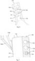
figs. 5-7 , the three predefined axial positions are in the second embodiment defined by three axially separated and identicalcircumferential grooves neck portion 117 of thefirst part 110, and aprotrusion 161 formed on thesecond part 150. Infig. 5 , thesecond part 150 is in a first axial position in which theprotrusion 161 is in engagement with a first one 131 of thecircumferential grooves protrusion 161 is dimensioned to be slidable along thegroove 131, i.e., thesecond part 150 is in the first axial position rotatable relative to thefirst part 110 around the axis A. - The
second part 150 is further moveable from the first axial position defined by the firstcircumferential groove 131 to a second axial position defined by a second one 132 of thecircumferential grooves groove 134 as illustrated infig. 6 . In the shown embodiment, the connectinggroove 134 extends in the axial direction from the firstcircumferential groove 131 to a third one 133 of thecircumferential grooves groove 134 has the same depth as thecircumferential grooves protrusion 161 to slide therein when moving thesecond part 150 in the axial direction relative to thefirst part 110. Of course, if more than oneprotrusion 161 is provided, more than one connectinggroove 134 must likewise be provided, so that each protrusion may slide in a corresponding connecting groove. - Hence, the first and
second parts circumferential grooves second part 150 relative to thefirst part 110 around the axis A such that theprotrusion 161 is moved along one of thecircumferential grooves groove 134 and to an interlocking position in which axial movement of thesecond part 150 relative to thefirst part 110 is prevented. In this way, several separate tools with unique calibration distances may be consolidated into onetool 100 withparts - It is not necessary that the
circumferential grooves neck portion 117, i.e., that thecircumferential grooves circumferential grooves protrusion 161 is unable to slide into the connectinggroove 134. - The
support arrangement 118 is in the second embodiment formed by twobeams neck portion 117 to thefirst arm 112 and thesecond arm 113 of thefirst engagement member 111, respectively. The twobeams first arm 118a to thebase 114. Thus, according to an example embodiment, thesupport arrangement 118 may be configured as a framework structure, such as a truss, implying a robust and light-weight configuration. As will be further discussed below, angles and dimensions of thesupport arrangement 118 may be set so as to enable additive manufacturing of thetool 100 without the use of support structures that must be removed after building thetool 100. - The
handle 120 comprises in the second embodiment a plurality ofrecesses 121 providing a structured gripping surface. Therecesses 121 further reduce the amount of material needed for forming thetool 100. Here, therecesses 121 are illustrated as elongated recesses having a helical extension, but there are of course many alternative surface structures that may be used to enhance friction and save weight in comparison with a non-patterned handle. - The
tool 100 may advantageously be manufactured using additive manufacturing, i.e., it is formed by material layers, which material layers are stacked onto one another along the axis A such that thefirst part 110 and thesecond part 150 are formed simultaneously. Such a manufacturing process using a 3D printing tool 1 is schematically illustrated infig. 8 . -
Fig. 8 is a simplified cross-section view of an example3D printing machine 800, which may be used to manufacture thetool 100 by Selective Laser Melting (SLM) process. During the SLM process, aproduct 880 is formed by selectively melting successive layers of powder by the interaction of a laser beam. Upon irradiation, the powder material is heated and, if sufficient power is applied, melts and forms a liquid pool. Afterwards, the molten pool solidifies and cools down quickly, and the consolidated material starts to form the product. After the cross-section of a layer is scanned, the building platform is lowered by an amount equal to the layer thickness and a new layer of powder is deposited. This process is repeated until the product is completed. - This layer-by-layer process is able to net-shape manufacture complex structures from a computer-aided design (CAD) model and a wide range of materials without the need of expensive tooling and machining so that the delay between design and manufacture is minimised.
- As shown in
fig. 8 , during the process,metal powder 810 in adispenser plate 820 is heated close to its melting point and spread by apowder recoater 830 on abuilding plate 840. Ascanning head 850 connected to alaser generator 860 draws or scans a cross section of apart 880, e.g., thetool 100, into the powder material. To form thetool 100, the cross sections of thefirst end 115 of thefirst part 110 and thefirst end 156 of thesecond part 150 are formed by the laser beam. After the cross-section of a layer is scanned, the building plate 640 is lowered corresponding to one layer thickness, which may be approximately 0.1 mm, after which the process is repeated until thetool 100 is completed when reaching thesecond end 158 of thesecond part 150. A collecting plate 670 is used for collecting the rest of un-melted metal powder. - As the finishing is done during the SLM process, no additional finishing is required except from removing un-melted metal powder. This process produces objects with very good finish.
- By adapting angles at which, e.g., the
support arrangement 118 and thecircumferential shoulder 158 of thesecond engagement member 151 extend with respect to the axis A, thetool 100 may be produced without any support structures for supporting overhanging features during the additive manufacturing process. To avoid using such support structures, the angle α between any overhanging feature of thetool 100 and a radial plane R of thetool 100 should preferably be above a threshold, such as at least 10°, or at least 20°, or at least 30°, as indicated infig. 5 . - Furthermore, the
tool 100 produced using additive manufacturing does not comprise any weak points such as welding joints or similar. Thetool 100 may, as in the second embodiment, be designed such that the amount of material needed is as small as possible. This is in the second embodiment achieved by, e.g., therecesses 121 of thehandle 120, open spaces between thebeams support structure 118, the hollowsecond part 150, and recesses formed in thecircumferential shoulder 157. - It is to be understood that the present disclosure is not limited to the embodiments described above and illustrated in the drawings; rather, the skilled person will recognize that many changes and modifications may be made within the scope of the appended claims.
Claims (15)
- A tool (100) for use in connection with calibration of a load sensor (200), the tool (100) comprising:- a first part (110) comprising a first engagement member (111) having a first contact surface (114) to contact a lever (210) of a load sensor (200), the lever (210) being moveably mounted to a structure (300);- a second part (150) comprising a second engagement member (151) having a second contact surface (152) to engage the structure (300), the second part (150) being irremovable from the first part (110);- wherein the second part (150) is moveable relative to the first part (110) along an axis (A) between at least two selectively lockable predefined axial positions, each predefined axial position providing a predefined axial distance between the first contact surface (114) and the second contact surface (152).
- The tool according to claim 1, wherein the first and second parts (110, 150) are selectively lockable relative to one another in the at least two predefined axial positions by rotation of the second part (150) relative to the first part (110) around the axis (A) to an interlocking position in which axial movement of the second part (150) relative to the first part (110) is prevented.
- The tool according to claim 1 or 2, wherein the first and second parts (110, 150) are selectively moveable between the predefined axial positions by rotation of the second part (150) relative to the first part (110) around the axis (A) to a moveable position in which axial movement of the second part (150) relative to the first part (110) is allowed.
- The tool according to any one of the preceding claims, wherein the at least two predefined axial positions are defined by at least one protrusion (161) formed on one of the first and second parts (110, 150), and at least two axially separated circumferential grooves (131, 132, 133) formed in the other one of the first and second parts (110, 150), wherein the at least one protrusion (161) is configured to selectively engage the circumferential grooves (131, 132, 133).
- The tool according to claim 4, wherein the at least two circumferential grooves (131, 132, 133) are connected by at least one connecting groove (134), wherein the at least one protrusion (161) is configured to selectively engage the at least one connecting groove (134) to move the second part (150) between the at least two predefined axial positions.
- The tool according to claim 4 or 5, wherein the at least one protrusion (161) comprises at least two protrusions distributed around a circumference of the part (110, 150), the at least two protrusions being configured for simultaneous engagement with the same circumferential groove.
- The tool according to any one of claims 4-6, wherein the at least one protrusion (161) is formed on the second part (150), and wherein the circumferential grooves (131, 132, 133) are formed in the first part (110).
- The tool according to any one of the preceding claims, wherein the first part (110) comprises an axially extending channel (119) in which the second part (150) is moveably received and from which the second part (150) extends.
- The tool according to any one of the preceding claims, wherein the first part (110) comprises a handle (120).
- The tool according to claim 9, wherein the handle (120) comprises recesses (121) providing a structured gripping surface.
- The tool according to any one of the preceding claims, wherein the first engagement member (111) comprises a radially extending base (114) and two axially extending arms (112, 113) extending from the base (114), the two axially extending arms (112, 113) and the radially extending base (114) forming a U-shaped slot for receiving the lever (210) of the load sensor (200), the radially extending base (114) defining the first contact surface (114).
- The tool according to any one of the preceding claims, wherein the second part (150) comprises a rod (154) and a circumferential shoulder (157) extending radially outward from the rod (154), the circumferential shoulder (157) defining the second contact surface (152) to abut the structure (300) when an end portion (155) of the rod (154) is received in an opening (301) defined in the structure (300).
- The tool according to any one of the preceding claims, wherein each one of the first and second parts (110, 150) is formed by material layers, which material layers are stacked onto one another along the axis (A).
- The tool according to any one of the preceding claims, wherein the first and second parts (110, 150) are made of the same material.
- The tool according to claim 14, wherein the material is a metal material.
Priority Applications (2)
| Application Number | Priority Date | Filing Date | Title |
|---|---|---|---|
| EP22171933.9A EP4273519B1 (en) | 2022-05-05 | 2022-05-05 | A tool for use during calibration of a sensor |
| US18/296,410 US12436019B2 (en) | 2022-05-05 | 2023-04-06 | Tool for use during calibration of a sensor |
Applications Claiming Priority (1)
| Application Number | Priority Date | Filing Date | Title |
|---|---|---|---|
| EP22171933.9A EP4273519B1 (en) | 2022-05-05 | 2022-05-05 | A tool for use during calibration of a sensor |
Publications (2)
| Publication Number | Publication Date |
|---|---|
| EP4273519A1 true EP4273519A1 (en) | 2023-11-08 |
| EP4273519B1 EP4273519B1 (en) | 2025-06-25 |
Family
ID=81585724
Family Applications (1)
| Application Number | Title | Priority Date | Filing Date |
|---|---|---|---|
| EP22171933.9A Active EP4273519B1 (en) | 2022-05-05 | 2022-05-05 | A tool for use during calibration of a sensor |
Country Status (2)
| Country | Link |
|---|---|
| US (1) | US12436019B2 (en) |
| EP (1) | EP4273519B1 (en) |
Family Cites Families (10)
| Publication number | Priority date | Publication date | Assignee | Title |
|---|---|---|---|---|
| CA1211954A (en) * | 1985-08-06 | 1986-09-30 | Michael J. Karpa | Device and procedure for testing heavy capacity scales |
| US4848478A (en) * | 1987-12-07 | 1989-07-18 | Pfister Gmbh | Method and apparatus for calibrating and/or checking of load cells |
| US5020357A (en) * | 1989-08-18 | 1991-06-04 | N. K. Biotechnical Engineering Company | Calibration stand for sensor |
| GB9818678D0 (en) * | 1998-08-28 | 1998-10-21 | Weighing Logistics Limited | Calibrating weighing installations |
| DE102009035410B4 (en) * | 2009-07-31 | 2017-03-16 | Horiba Europe Gmbh | Test bench with a device for calibrating a force-measuring device |
| US9389135B2 (en) * | 2013-09-26 | 2016-07-12 | WD Media, LLC | Systems and methods for calibrating a load cell of a disk burnishing machine |
| US11624648B2 (en) * | 2019-07-09 | 2023-04-11 | Pelstar, Llc | Systems and methods for scale calibration |
| CN111351615B (en) * | 2020-03-25 | 2021-07-20 | 东南大学 | High-precision and miniaturized on-orbit calibration device and calibration method for six-dimensional force sensor of space station manipulator |
| CN212721902U (en) * | 2020-07-09 | 2021-03-16 | 东风安道拓汽车座椅有限公司 | Force sensor calibration tool |
| ES3059143T3 (en) * | 2021-10-21 | 2026-03-19 | Eilersen Calibration Solutions Aps | A calibration device for weighing systems |
-
2022
- 2022-05-05 EP EP22171933.9A patent/EP4273519B1/en active Active
-
2023
- 2023-04-06 US US18/296,410 patent/US12436019B2/en active Active
Non-Patent Citations (2)
| Title |
|---|
| ANONYMOUS: "EXTENDING WHEEL NUT WRENCH", 15 January 2005 (2005-01-15), XP002807659, Retrieved from the Internet <URL:https://www.kincrome.com.au/ext-wheel-nut-wrench> [retrieved on 20221005] * |
| ANONYMOUS: "Spanner met 2 klemmen", 13 January 2010 (2010-01-13), XP002807658, Retrieved from the Internet <URL:https://www.manutan.nl/nl/mnl/spanner-met-2-klemmen-a003008?gclid=EAIaIQobChMIkdbH46HJ-gIVCL53Ch3F6gZgEAQYASABEgIDJfD_BwE> [retrieved on 20221005] * |
Also Published As
| Publication number | Publication date |
|---|---|
| US12436019B2 (en) | 2025-10-07 |
| EP4273519B1 (en) | 2025-06-25 |
| US20230358595A1 (en) | 2023-11-09 |
Similar Documents
| Publication | Publication Date | Title |
|---|---|---|
| US8783078B2 (en) | Method to improve geometrical accuracy of an incrementally formed workpiece | |
| CN109475958B (en) | Method for establishing welding parameters of a welding process | |
| US8302442B2 (en) | Method of incrementally forming a workpiece | |
| US10112641B2 (en) | Guide tube for a steering shaft and method for producing same | |
| US10890440B2 (en) | 3D floating support system and related geometry-detecting machine of slender articles | |
| EP4273519B1 (en) | A tool for use during calibration of a sensor | |
| CA2552120C (en) | Low profile turntable assembly | |
| Simonetto et al. | In-process measurement of springback in tube rotary draw bending | |
| EP4042061B1 (en) | A device for supporting a load | |
| Teng et al. | Techniques for buckling experiments on steel silo transition junctions | |
| JP2024507062A (en) | Method and system for forming tubular or frustoconical segments | |
| Hergul et al. | Performance and microstructure analysis of cylindrical rods fabricated by dot-by-dot waam for aerospace applications | |
| US7971496B2 (en) | Method for determining the elastic deformation of components | |
| US20230356315A1 (en) | Cold Working During Additive Manufacturing | |
| EP1631402B1 (en) | Method for manufacturing hollow construction elements | |
| CN214721931U (en) | Repair welding tool for cylindrical castings | |
| Singh et al. | Experimental force modeling for deformation machining stretching mode for aluminum alloys | |
| CN114951953A (en) | Welding force control device and method during space weld joint friction stir welding | |
| Werner et al. | Freeform Bending Tool Design for Rectangular Profiles and Its Influence on the Process | |
| JP5631370B2 (en) | Left and right suspension mounting method and mounting apparatus for vehicle body | |
| Bolot et al. | Development of WAAM process: slicer, robot trajectories, and examples of parts | |
| Müller et al. | Design and Parameter Identification of Wire and Arc Additively Manufactured (WAAM) Steel Bars for Use | |
| WO2003035298A1 (en) | A die for simultaneous deep drawing and ironing processes, a product produced by use of such die and a method for producing such product | |
| Becker et al. | Manufacture of 3D curved profiles for structure components | |
| CN121139755A (en) | A method and tooling for aligning large-diameter, multi-type pipes |
Legal Events
| Date | Code | Title | Description |
|---|---|---|---|
| PUAI | Public reference made under article 153(3) epc to a published international application that has entered the european phase |
Free format text: ORIGINAL CODE: 0009012 |
|
| STAA | Information on the status of an ep patent application or granted ep patent |
Free format text: STATUS: THE APPLICATION HAS BEEN PUBLISHED |
|
| AK | Designated contracting states |
Kind code of ref document: A1 Designated state(s): AL AT BE BG CH CY CZ DE DK EE ES FI FR GB GR HR HU IE IS IT LI LT LU LV MC MK MT NL NO PL PT RO RS SE SI SK SM TR |
|
| STAA | Information on the status of an ep patent application or granted ep patent |
Free format text: STATUS: REQUEST FOR EXAMINATION WAS MADE |
|
| 17P | Request for examination filed |
Effective date: 20240223 |
|
| RBV | Designated contracting states (corrected) |
Designated state(s): AL AT BE BG CH CY CZ DE DK EE ES FI FR GB GR HR HU IE IS IT LI LT LU LV MC MK MT NL NO PL PT RO RS SE SI SK SM TR |
|
| GRAP | Despatch of communication of intention to grant a patent |
Free format text: ORIGINAL CODE: EPIDOSNIGR1 |
|
| STAA | Information on the status of an ep patent application or granted ep patent |
Free format text: STATUS: GRANT OF PATENT IS INTENDED |
|
| INTG | Intention to grant announced |
Effective date: 20250207 |
|
| RAP3 | Party data changed (applicant data changed or rights of an application transferred) |
Owner name: VOLVO TRUCK CORPORATION |
|
| GRAS | Grant fee paid |
Free format text: ORIGINAL CODE: EPIDOSNIGR3 |
|
| GRAA | (expected) grant |
Free format text: ORIGINAL CODE: 0009210 |
|
| STAA | Information on the status of an ep patent application or granted ep patent |
Free format text: STATUS: THE PATENT HAS BEEN GRANTED |
|
| AK | Designated contracting states |
Kind code of ref document: B1 Designated state(s): AL AT BE BG CH CY CZ DE DK EE ES FI FR GB GR HR HU IE IS IT LI LT LU LV MC MK MT NL NO PL PT RO RS SE SI SK SM TR |
|
| REG | Reference to a national code |
Ref country code: GB Ref legal event code: FG4D |
|
| REG | Reference to a national code |
Ref country code: CH Ref legal event code: EP |
|
| REG | Reference to a national code |
Ref country code: DE Ref legal event code: R096 Ref document number: 602022016308 Country of ref document: DE |
|
| REG | Reference to a national code |
Ref country code: CH Ref legal event code: EP |
|
| REG | Reference to a national code |
Ref country code: IE Ref legal event code: FG4D |
|
| PG25 | Lapsed in a contracting state [announced via postgrant information from national office to epo] |
Ref country code: FI Free format text: LAPSE BECAUSE OF FAILURE TO SUBMIT A TRANSLATION OF THE DESCRIPTION OR TO PAY THE FEE WITHIN THE PRESCRIBED TIME-LIMIT Effective date: 20250625 |
|
| REG | Reference to a national code |
Ref country code: LT Ref legal event code: MG9D |
|
| PG25 | Lapsed in a contracting state [announced via postgrant information from national office to epo] |
Ref country code: GR Free format text: LAPSE BECAUSE OF FAILURE TO SUBMIT A TRANSLATION OF THE DESCRIPTION OR TO PAY THE FEE WITHIN THE PRESCRIBED TIME-LIMIT Effective date: 20250926 Ref country code: NO Free format text: LAPSE BECAUSE OF FAILURE TO SUBMIT A TRANSLATION OF THE DESCRIPTION OR TO PAY THE FEE WITHIN THE PRESCRIBED TIME-LIMIT Effective date: 20250925 |
|
| PG25 | Lapsed in a contracting state [announced via postgrant information from national office to epo] |
Ref country code: BG Free format text: LAPSE BECAUSE OF FAILURE TO SUBMIT A TRANSLATION OF THE DESCRIPTION OR TO PAY THE FEE WITHIN THE PRESCRIBED TIME-LIMIT Effective date: 20250625 |
|
| PG25 | Lapsed in a contracting state [announced via postgrant information from national office to epo] |
Ref country code: HR Free format text: LAPSE BECAUSE OF FAILURE TO SUBMIT A TRANSLATION OF THE DESCRIPTION OR TO PAY THE FEE WITHIN THE PRESCRIBED TIME-LIMIT Effective date: 20250625 |
|
| PG25 | Lapsed in a contracting state [announced via postgrant information from national office to epo] |
Ref country code: RS Free format text: LAPSE BECAUSE OF FAILURE TO SUBMIT A TRANSLATION OF THE DESCRIPTION OR TO PAY THE FEE WITHIN THE PRESCRIBED TIME-LIMIT Effective date: 20250925 |
|
| PG25 | Lapsed in a contracting state [announced via postgrant information from national office to epo] |
Ref country code: LV Free format text: LAPSE BECAUSE OF FAILURE TO SUBMIT A TRANSLATION OF THE DESCRIPTION OR TO PAY THE FEE WITHIN THE PRESCRIBED TIME-LIMIT Effective date: 20250625 |
|
| REG | Reference to a national code |
Ref country code: NL Ref legal event code: MP Effective date: 20250625 |
|
| PG25 | Lapsed in a contracting state [announced via postgrant information from national office to epo] |
Ref country code: NL Free format text: LAPSE BECAUSE OF FAILURE TO SUBMIT A TRANSLATION OF THE DESCRIPTION OR TO PAY THE FEE WITHIN THE PRESCRIBED TIME-LIMIT Effective date: 20250625 |
|
| PG25 | Lapsed in a contracting state [announced via postgrant information from national office to epo] |
Ref country code: PT Free format text: LAPSE BECAUSE OF FAILURE TO SUBMIT A TRANSLATION OF THE DESCRIPTION OR TO PAY THE FEE WITHIN THE PRESCRIBED TIME-LIMIT Effective date: 20251027 |
|
| REG | Reference to a national code |
Ref country code: AT Ref legal event code: MK05 Ref document number: 1806863 Country of ref document: AT Kind code of ref document: T Effective date: 20250625 |
|
| PG25 | Lapsed in a contracting state [announced via postgrant information from national office to epo] |
Ref country code: IS Free format text: LAPSE BECAUSE OF FAILURE TO SUBMIT A TRANSLATION OF THE DESCRIPTION OR TO PAY THE FEE WITHIN THE PRESCRIBED TIME-LIMIT Effective date: 20251025 |
|
| PG25 | Lapsed in a contracting state [announced via postgrant information from national office to epo] |
Ref country code: AT Free format text: LAPSE BECAUSE OF FAILURE TO SUBMIT A TRANSLATION OF THE DESCRIPTION OR TO PAY THE FEE WITHIN THE PRESCRIBED TIME-LIMIT Effective date: 20250625 Ref country code: SM Free format text: LAPSE BECAUSE OF FAILURE TO SUBMIT A TRANSLATION OF THE DESCRIPTION OR TO PAY THE FEE WITHIN THE PRESCRIBED TIME-LIMIT Effective date: 20250625 |
|
| PG25 | Lapsed in a contracting state [announced via postgrant information from national office to epo] |
Ref country code: CZ Free format text: LAPSE BECAUSE OF FAILURE TO SUBMIT A TRANSLATION OF THE DESCRIPTION OR TO PAY THE FEE WITHIN THE PRESCRIBED TIME-LIMIT Effective date: 20250625 |
|
| PG25 | Lapsed in a contracting state [announced via postgrant information from national office to epo] |
Ref country code: PL Free format text: LAPSE BECAUSE OF FAILURE TO SUBMIT A TRANSLATION OF THE DESCRIPTION OR TO PAY THE FEE WITHIN THE PRESCRIBED TIME-LIMIT Effective date: 20250625 |
|
| PG25 | Lapsed in a contracting state [announced via postgrant information from national office to epo] |
Ref country code: EE Free format text: LAPSE BECAUSE OF FAILURE TO SUBMIT A TRANSLATION OF THE DESCRIPTION OR TO PAY THE FEE WITHIN THE PRESCRIBED TIME-LIMIT Effective date: 20250625 |
|
| PG25 | Lapsed in a contracting state [announced via postgrant information from national office to epo] |
Ref country code: SK Free format text: LAPSE BECAUSE OF FAILURE TO SUBMIT A TRANSLATION OF THE DESCRIPTION OR TO PAY THE FEE WITHIN THE PRESCRIBED TIME-LIMIT Effective date: 20250625 |
|
| PG25 | Lapsed in a contracting state [announced via postgrant information from national office to epo] |
Ref country code: ES Free format text: LAPSE BECAUSE OF FAILURE TO SUBMIT A TRANSLATION OF THE DESCRIPTION OR TO PAY THE FEE WITHIN THE PRESCRIBED TIME-LIMIT Effective date: 20250625 |
|
| PG25 | Lapsed in a contracting state [announced via postgrant information from national office to epo] |
Ref country code: DK Free format text: LAPSE BECAUSE OF FAILURE TO SUBMIT A TRANSLATION OF THE DESCRIPTION OR TO PAY THE FEE WITHIN THE PRESCRIBED TIME-LIMIT Effective date: 20250625 |
|
| PG25 | Lapsed in a contracting state [announced via postgrant information from national office to epo] |
Ref country code: IT Free format text: LAPSE BECAUSE OF FAILURE TO SUBMIT A TRANSLATION OF THE DESCRIPTION OR TO PAY THE FEE WITHIN THE PRESCRIBED TIME-LIMIT Effective date: 20250625 |
|
| PLBE | No opposition filed within time limit |
Free format text: ORIGINAL CODE: 0009261 |
|
| STAA | Information on the status of an ep patent application or granted ep patent |
Free format text: STATUS: NO OPPOSITION FILED WITHIN TIME LIMIT |
|
| REG | Reference to a national code |
Ref country code: CH Ref legal event code: L10 Free format text: ST27 STATUS EVENT CODE: U-0-0-L10-L00 (AS PROVIDED BY THE NATIONAL OFFICE) Effective date: 20260507 |