EP4273472A1 - Ice making assembly and refrigerator - Google Patents
Ice making assembly and refrigerator Download PDFInfo
- Publication number
- EP4273472A1 EP4273472A1 EP21914701.4A EP21914701A EP4273472A1 EP 4273472 A1 EP4273472 A1 EP 4273472A1 EP 21914701 A EP21914701 A EP 21914701A EP 4273472 A1 EP4273472 A1 EP 4273472A1
- Authority
- EP
- European Patent Office
- Prior art keywords
- ice
- heat
- ice mold
- mold
- conducting member
- Prior art date
- Legal status (The legal status is an assumption and is not a legal conclusion. Google has not performed a legal analysis and makes no representation as to the accuracy of the status listed.)
- Pending
Links
- 239000003507 refrigerant Substances 0.000 claims abstract description 55
- 238000010438 heat treatment Methods 0.000 claims abstract description 40
- XLYOFNOQVPJJNP-UHFFFAOYSA-N water Substances O XLYOFNOQVPJJNP-UHFFFAOYSA-N 0.000 claims abstract description 34
- 230000007246 mechanism Effects 0.000 claims description 15
- 230000008014 freezing Effects 0.000 claims description 12
- 238000007710 freezing Methods 0.000 claims description 12
- 230000006872 improvement Effects 0.000 description 11
- 230000008018 melting Effects 0.000 description 7
- 238000002844 melting Methods 0.000 description 7
- 238000009434 installation Methods 0.000 description 5
- 238000005057 refrigeration Methods 0.000 description 4
- 238000001816 cooling Methods 0.000 description 2
- 238000004519 manufacturing process Methods 0.000 description 2
- 238000003860 storage Methods 0.000 description 2
- 238000010521 absorption reaction Methods 0.000 description 1
- 230000009471 action Effects 0.000 description 1
- 229910052782 aluminium Inorganic materials 0.000 description 1
- XAGFODPZIPBFFR-UHFFFAOYSA-N aluminium Chemical compound [Al] XAGFODPZIPBFFR-UHFFFAOYSA-N 0.000 description 1
- 230000000903 blocking effect Effects 0.000 description 1
- 230000008020 evaporation Effects 0.000 description 1
- 238000001704 evaporation Methods 0.000 description 1
- 238000005429 filling process Methods 0.000 description 1
- 238000009413 insulation Methods 0.000 description 1
- 229910052751 metal Inorganic materials 0.000 description 1
- 239000002184 metal Substances 0.000 description 1
- 238000012986 modification Methods 0.000 description 1
- 230000004048 modification Effects 0.000 description 1
Images


Classifications
-
- F—MECHANICAL ENGINEERING; LIGHTING; HEATING; WEAPONS; BLASTING
- F25—REFRIGERATION OR COOLING; COMBINED HEATING AND REFRIGERATION SYSTEMS; HEAT PUMP SYSTEMS; MANUFACTURE OR STORAGE OF ICE; LIQUEFACTION SOLIDIFICATION OF GASES
- F25C—PRODUCING, WORKING OR HANDLING ICE
- F25C5/00—Working or handling ice
- F25C5/02—Apparatus for disintegrating, removing or harvesting ice
- F25C5/04—Apparatus for disintegrating, removing or harvesting ice without the use of saws
- F25C5/08—Apparatus for disintegrating, removing or harvesting ice without the use of saws by heating bodies in contact with the ice
-
- F—MECHANICAL ENGINEERING; LIGHTING; HEATING; WEAPONS; BLASTING
- F25—REFRIGERATION OR COOLING; COMBINED HEATING AND REFRIGERATION SYSTEMS; HEAT PUMP SYSTEMS; MANUFACTURE OR STORAGE OF ICE; LIQUEFACTION SOLIDIFICATION OF GASES
- F25D—REFRIGERATORS; COLD ROOMS; ICE-BOXES; COOLING OR FREEZING APPARATUS NOT OTHERWISE PROVIDED FOR
- F25D11/00—Self-contained movable devices, e.g. domestic refrigerators
- F25D11/02—Self-contained movable devices, e.g. domestic refrigerators with cooling compartments at different temperatures
-
- F—MECHANICAL ENGINEERING; LIGHTING; HEATING; WEAPONS; BLASTING
- F25—REFRIGERATION OR COOLING; COMBINED HEATING AND REFRIGERATION SYSTEMS; HEAT PUMP SYSTEMS; MANUFACTURE OR STORAGE OF ICE; LIQUEFACTION SOLIDIFICATION OF GASES
- F25C—PRODUCING, WORKING OR HANDLING ICE
- F25C1/00—Producing ice
- F25C1/04—Producing ice by using stationary moulds
-
- F—MECHANICAL ENGINEERING; LIGHTING; HEATING; WEAPONS; BLASTING
- F25—REFRIGERATION OR COOLING; COMBINED HEATING AND REFRIGERATION SYSTEMS; HEAT PUMP SYSTEMS; MANUFACTURE OR STORAGE OF ICE; LIQUEFACTION SOLIDIFICATION OF GASES
- F25C—PRODUCING, WORKING OR HANDLING ICE
- F25C1/00—Producing ice
- F25C1/22—Construction of moulds; Filling devices for moulds
- F25C1/24—Construction of moulds; Filling devices for moulds for refrigerators, e.g. freezing trays
-
- F—MECHANICAL ENGINEERING; LIGHTING; HEATING; WEAPONS; BLASTING
- F25—REFRIGERATION OR COOLING; COMBINED HEATING AND REFRIGERATION SYSTEMS; HEAT PUMP SYSTEMS; MANUFACTURE OR STORAGE OF ICE; LIQUEFACTION SOLIDIFICATION OF GASES
- F25D—REFRIGERATORS; COLD ROOMS; ICE-BOXES; COOLING OR FREEZING APPARATUS NOT OTHERWISE PROVIDED FOR
- F25D21/00—Defrosting; Preventing frosting; Removing condensed or defrost water
- F25D21/06—Removing frost
- F25D21/08—Removing frost by electric heating
-
- F—MECHANICAL ENGINEERING; LIGHTING; HEATING; WEAPONS; BLASTING
- F25—REFRIGERATION OR COOLING; COMBINED HEATING AND REFRIGERATION SYSTEMS; HEAT PUMP SYSTEMS; MANUFACTURE OR STORAGE OF ICE; LIQUEFACTION SOLIDIFICATION OF GASES
- F25D—REFRIGERATORS; COLD ROOMS; ICE-BOXES; COOLING OR FREEZING APPARATUS NOT OTHERWISE PROVIDED FOR
- F25D21/00—Defrosting; Preventing frosting; Removing condensed or defrost water
- F25D21/14—Collecting or removing condensed and defrost water; Drip trays
-
- F—MECHANICAL ENGINEERING; LIGHTING; HEATING; WEAPONS; BLASTING
- F25—REFRIGERATION OR COOLING; COMBINED HEATING AND REFRIGERATION SYSTEMS; HEAT PUMP SYSTEMS; MANUFACTURE OR STORAGE OF ICE; LIQUEFACTION SOLIDIFICATION OF GASES
- F25C—PRODUCING, WORKING OR HANDLING ICE
- F25C2305/00—Special arrangements or features for working or handling ice
- F25C2305/024—Rotating rake
-
- F—MECHANICAL ENGINEERING; LIGHTING; HEATING; WEAPONS; BLASTING
- F25—REFRIGERATION OR COOLING; COMBINED HEATING AND REFRIGERATION SYSTEMS; HEAT PUMP SYSTEMS; MANUFACTURE OR STORAGE OF ICE; LIQUEFACTION SOLIDIFICATION OF GASES
- F25D—REFRIGERATORS; COLD ROOMS; ICE-BOXES; COOLING OR FREEZING APPARATUS NOT OTHERWISE PROVIDED FOR
- F25D23/00—General constructional features
- F25D23/02—Doors; Covers
- F25D23/04—Doors; Covers with special compartments, e.g. butter conditioners
Definitions
- the present invention relates to the field of refrigerating appliances, and particularly to an ice-making assembly and a refrigerator.
- An ice maker is usually disposed in a freezing chamber of a refrigerator to make ice by virtue of the cold air in the freezing chamber.
- a refrigerator with a refrigerating chamber above the freezing chamber a user needs to bend down to open the door body of the freezing chamber upon taking out of ice.
- an independent ice-making chamber is disposed in the refrigerating chamber or a door body of the refrigerating chamber of some conventional refrigerators, the ice maker is disposed in the ice-making chamber, and a dispenser associated with the ice maker is disposed on an outer side of the door body.
- the cold air of the freezing chamber and the evaporator chamber is introduced through an air duct into the air-making chamber to achieve the supply of cold to the ice maker.
- Such an ice making manner is also referred to as air-cooled ice making.
- the ice-making efficiency in the air-chilled ice-making manner is low, and the air duct occupies a large space, thus occupying the storage space of the refrigerator itself. For this reason, there occurs a manner of making ice through direct contact between the refrigeration pipeline and the ice-maker, and the manner is referred to as direct-cooling ice-making.
- the direct-cooling ice-making has advantages such as quick ice making and a small occupation of space. Therefore, how to achieve effective connection of the refrigeration pipeline and an ice mold of the ice maker is particularly important.
- An object of the present invention is to provide an ice making assembly which is convenient to install and has a high ice-making efficiency.
- Another object of the present invention is to provide a refrigerator in which an ice-making assembly is convenient to mount and the ice-making efficiency is high.
- an ice-making assembly comprising:
- top wall is provided with a first groove and a second groove respectively matching outer shapes of the refrigerant pipe and the heating wire, a portion of the refrigerant pipe is received in the first groove, a portion of the heating wire is received in the second groove, and the heat-dissipating ribs are positioned corresponding to the first groove.
- the bottom cover comprises a first enclosing wall and a second enclosing wall corresponding to the two side walls, a snap-fitting protrusion is provided on one of each enclosing wall and the corresponding side wall, a snap-fitting slot is provided on the other of each enclosing wall and the corresponding side wall, and the heat-conducting member and the bottom cover are fixedly connected via the snap-fitting protrusion and the snap-fitting slot.
- the ice-making assembly further comprises a housing fixed to the ice mold, the housing has a first edge and a second edge respectively corresponding to the first enclosing wall and the second enclosing wall, a lug provided with a snap-fitting hook or hook slot extends from the first edge and the second edge respectively, the two enclosing walls are respectively provided with a hook slot or snap-fitting hook, and the bottom cover and the housing are fixedly connected via the hook slot and snap-fitting hook.
- an ice guide is fixedly connected to the front end of the ice mold, and the ice guide extends downwards to a position flush with the snap-fitting hook.
- the housing further comprises a back plate extending upwardly from an end perpendicular to an extension direction of the ice mold, and the ice-making assembly is mounted to an interior of the refrigerator by a mounting structure on the back plate.
- the top wall is further provided with a convex portion extending in a direction from one end to the other of the ice mold, the convex portion is located in the interior of the U-shape of the refrigerant pipe, and the convex portion is in direct contact with the bottom of the ice mold.
- a protruding rim protruding upwards is disposed at both ends of the bottom cover, and the heat-conducting member is snap-fitted between the two protruding rims.
- the ice-making assembly further comprises a driving mechanism connected to an end of the ice mold, the bottom wall is arranged to be inclined downwards in a direction from one end of the ice mold connected to the driving mechanism to the other end, and the bottom wall is inclined downwards in a front-rear direction.
- the ice-making assembly further comprises a housing fixed with the ice mold, one end of the housing away from the driving mechanism forms an upwardly-extending end plate, a water filling trough is disposed on an outer side of the end plate relative to the ice mold, the water filling trough is communicated with the ice cells, and the water filling tough, the ice mold and the housing are integrally formed.
- the present invention provides a refrigerator, comprising:
- the heat-conducting member is fixed to the ice mold via the bottom cover; upon assembling, the only thing to do is placing the refrigerant pipe and the heating wire between the ice mold and the heat-conducting member, and connecting the bottom cover with the ice mold, so as to achieve heat transfer of the refrigerant pipe and the heating wire to the ice mold.
- the mounting is very convenient.
- the heat-conducting member and the heat-dissipating ribs thereof can also achieve heat exchange with the air in the airflow chamber, thereby facilitating the supply of cold to other portions.
- the manner in which the refrigerant pipe and the heating wire simultaneously contact the ice mold and heat-conducting member enables a higher utilization ratio of cold and heat and a faster heat transfer, thereby enabling an improvement in ice-making efficiency.
- spatial relative positions such as “up”, “down”, “in” and “out” used in the text herein are intended to describe a relationship of one unit or feature shown in figures relative to another unit or feature for an easy description purpose.
- the terms indicating spatial relative positions may be intended to include different orientations besides the orientations shown in the figures in use or operation of the device.
- a preferred embodiment of the present invention provides an ice-making assembly 100 comprising an ice mold 10, and a refrigerant pipe 20 and a heating wire 30 located at a bottom of the ice mold 10, wherein the ice mold 10 has a plurality of ice cells for containing ice-making water, the refrigerant pipe 20 extends from one end to the other end of the ice mold 10, and the heating wire 30 is spaced apart from the refrigerant pipe 20, and preferably spaced apart from the refrigerant pipe 20 in a direction substantially perpendicular to an extension direction of the ice mold 20.
- the refrigerant pipe 20 is configured to supply cold to the ice mold 10 to freeze water in the ice cells
- the heating wire 30 is configured to supply heat to the ice mold 10 to facilitate release of ice cubes from the ice mold 10.
- a direction in which the ice mold extends lengthwise from one end to the other end is taken as a transverse direction
- a side from which the ice cubes are released from the ice mold is taken as a front side
- the opposite side is taken as a rear side
- a direction perpendicular to the transverse direction and the front-rear direction is taken as a vertical direction.
- the ice-making assembly 100 further comprises a heat-conducting member 40 and a bottom cover 50 surrounding the outside of the heat-conducting member 40, wherein the heat-conducting member 40 is disposed between the ice mold 10 and the bottom cover 50, the refrigerant pipe 20 and the heating wire 30 are positioned between the ice mold 10 and the heat-conducting member 40, and the heat-conducting member 40 supports at least a portion of the refrigerant pipe 20 and at least a portion of the heating wire 30 such that the at least a portion of the refrigerant pipe 20 and the at least a portion of the heating wire 30 are in direct contact with the ice mold 10 to transfer cold and heat to the ice mold 10. With the heat exchange being performed by direct contact, the transfer of heat and cold is more efficient, thereby greatly improving the ice-making efficiency.
- the heat-conducting member 40 comprises a top wall 41 adjacent to the ice mold 10, an opposite bottom wall 42 and two side walls 43 connecting the top wall 41 with the bottom wall 42, wherein the top wall 41, the bottom wall 42 and the two side walls 43 enclose an airflow chamber 44 which is through in a direction from one end to the other end of the ice mold 10, heat-dissipating ribs 45 extending from the top wall 41 to the bottom wall 42 are provided in the airflow chamber 44, a water outlet 421 is formed at an end of the bottom wall 42, the bottom cover 50 surrounds the bottom wall 42 and the two side walls 43, and the heat-conducting member 40 is fixed to the ice mold 10 via the bottom cover 50.
- the heat transfer of the refrigerant pipe 20 and the heating wire 30 to the ice mold 10 may be achieved only by placing the refrigerant pipe 20 and the heating wire 30 between the ice mold 10 and the heat-conducting member 40, and connecting the bottom cover 50 with the ice mold 10.
- the mounting is very convenient.
- the heat-conducting member 40 and the heat-dissipating ribs thereof can also achieve heat exchange with the air in the airflow chamber, thereby facilitating the supply of cold to other portions such as an ice bin below the ice-making assembly 100 to prevent the stored ice cubes from melting.
- the heat-conducting member 40 may also melt the frost by virtue of the heat of the heating wire 30, and the water resulting from the melting of the frost may be directly discharged through the water outlet 421.
- the manner in which the refrigerant pipe 20 and the heating wire 30 simultaneously contact the ice mold 10 and the heat-conducting member 40 enables a higher utilization ratio of cold and heat and a faster heat transfer, thereby enabling an improvement in ice-making efficiency.
- the ice mold needs to be cleaned, regardless of disassembly or installation, it is only necessary to connect the ice mold with the bottom cover by aligning relevant parts in position, so that the installation is very convenient.
- the top wall 41 of the heat-conducting member 40 is provided with a first groove 411 and a second groove 412 respectively matching the outer shapes of the refrigerant pipe 20 and the heating wire 30, and a portion of the refrigerant pipe 20 is received in the first groove 411 and a portion of the heating wire 30 is received in the second groove 412.
- a portion of the refrigerant pipe 20 in contact with the ice mold 10 is constructed in a U-shape
- the heating wire 30 is also constructed in a U-shape
- the refrigerant pipe 20 and the heating wire 30 are arranged oppositely, i.e., the two U-shapes open in opposite directions
- the refrigerant pipe 20 is located on an inner side of the U-shape of the heating wire 30.
- the ice-making assembly 100 further comprises a driving mechanism 60 at an end of the ice mold 10, and the driving mechanism 60 is used to bring an ice discharger 70 on the ice mold 10 to rotate to perform deicing.
- An open end of the U-shape of the heating wire 30 faces towards the driving mechanism 60 to facilitate making electrical connection.
- the open end of the U-shape of the refrigerant pipe 20 faces away from the driving mechanism 60 to facilitate connection with the refrigeration pipeline.
- the heat-dissipating ribs 45 are arranged at positions corresponding to the first grooves 411, so that the heat-dissipating ribs 42 are closer to the refrigerant pipe 20, thereby facilitating the absorption of the cold of the refrigerant pipe 20, and thereby improving the refrigerating efficiency.
- the heat-conducting member 40 is preferably made of a metal, such as an integrally-formed aluminum member. The heat-conducting member 40 is convenient to manufacture and meanwhile has high heat conductivity.
- the top wall 41 of the heat-conducting member 10 is further provided with a convex portion 413 extending in a direction from one end to the other end of the ice mold 10, the convex portion 413 is in direct contact with the bottom of the ice mold 10, the convex portion 413 is located in an interior of the U-shape of the refrigerant pipe, and the heat-conducting member 40 receives the cold on the refrigerant pipe 20 and further conducts the cold to the ice mold 10 again through the convex portion 413, thereby quickening the conduction of col and improving the ice-making efficiency.
- a surface of the convex portion 413 facing the airflow chamber forms a groove 414, that is, a wall thickness of the top wall 41 of the heat-conducting member 10 is substantially uniform, so that the surface area in contact with the airflow can be increased, thereby improving the heat exchange efficiency.
- the refrigerant pipe 20 is wrapped by the ice mold 10 and the heat-conducting member 40. Frost will be formed on a surface inside the airflow chamber 44 of the heat-conducting member 40.
- the heat-conducting member 40 As the heating wire 30 is activated to de-ice, the heat-conducting member 40 meanwhile absorbs heat to melt the frost, and the water resulting from the melting of the frost flows to the bottom wall 42 directly along the surface inside the airflow chamber 44; in order to speed up water drainage, the bottom wall 42 may be arranged to be inclined downwards in a direction from one end of the ice mold 10 connected to the driving mechanism 60 to the other end, with an inclination angle ⁇ being in a range of about 0.5-2.5 degrees. Furthermore, the bottom wall 42 is inclined downwards in a front-rear direction, with an inclination angle ⁇ being in a range of 3-5 degrees.
- the water outlet 421 is disposed at an end of the bottom wall 42 away from the driving mechanism 60 and at a rear end of the heat conducting member 40, i.e., at the lowest part of the bottom wall 42, so that the water resulting from the melting of the frost can be sufficiently drained. Furthermore, a water blocking edge 423 is provided at an end of the bottom wall 42 away from an end of the driving mechanism 60 to prevent overflow when the water resulting from the melting of the frost is excessive.
- the bottom cover 50 comprises a first enclosing wall 51 and a second enclosing wall 52 corresponding to the two side walls, wherein a snap-fitting protrusion 511 is provided on one of each enclosing wall and the corresponding side wall, and a snap-fitting slot 431 is provided on the other of each enclosing wall and the corresponding side wall, and the heat-conducting member 40 and the bottom cover 50 are fixedly connected via the snap-fitting protrusion 511 and the snap-fitting slot 431.
- three snap-fitting slots 431 are disposed at an interval on each side wall 43 in an extension direction of the ice mold 10 from one end to the other end, and the first enclosing wall 51 and the second enclosing wall 52 are respectively provided with snap-fitting protrusions 511 corresponding to the snap-fitting slots 431.
- a thermal insulation panel 55 may be disposed between the bottom cover 50 and the bottom wall of the heat-conducting member 40 to insulate the heat transfer from the heat-conducting member 40 to the bottom cover 50 and prevent frost from being formed on the bottom cover 50.
- a protruding rim 54 protruding upwards is disposed at both ends of the bottom cover 50.
- the heat-conducting member 40 is snap-fitted between the two protruding rims 54.
- the first enclosing wall 51, the second enclosing wall 52 and the two protruding rims 54 enable the accurate positioning of the heat-conducting member 40 relative to the bottom cover 50 in two directions, so that the positioning and the fixing of the heat-conducting member 40 is more reliable.
- the ice-making assembly 100 further comprises a housing 15 fixed to the ice mold 10, wherein the housing 15 has a first edge 151 and a second edge 152 respectively corresponding to the first enclosing wall 51 and the second enclosing wall 52, a lug 153 provided with a snap-fitting hook or hook slot extends from the first edge 151 and the second edge 152 respectively, the two enclosing walls are respectively provided with a hook slot or snap-fitting hook, and the bottom cover 50 and the housing 15 are fixedly connected via the hook slot and snap-fitting hook.
- the heat-conducting member 40 may be maintained in a relatively fixed position, thereby enabling the refrigerant pipe 20 and the heating wire 30 to keep in contact with the ice mold 10, so that the heat transfer is more reliable.
- two lugs 153 extend downwards from the first edge 151 and the second edge 152, respectively, namely, two lugs 153 are provided at a front end of the ice mold 10, two lugs 153 are provided at a rear end of the ice mold 10, hook slots are provided on the lugs 153, and snap-fitting hooks are correspondingly provided on the two enclosing walls 51 and 52.
- An ice guide 16 is fixedly connected to the front end of the ice mold 10 to prevent falling ice cubes from hitting the snap-fitting hooks or the hook slots upon deicing.
- the ice guide 16 extends downwards to a position flush with the snap-fitting hooks.
- the housing 15 and the ice mold 10 are integrally formed to simplify the installation of the entire ice-making assembly 100.
- the housing 15 has a front end and an opposite rear end, the rear end of the housing 15 forms an upwardly-extending back plate 155, a mounting structure is provided on the back plate 155 for mounting the ice-making assembly 100 inside the refrigerator, and the driving mechanism 60 may be mounted on the housing 15. As such, only the housing 15 needs to be fixedly connected to the refrigerator, so the mounting is more convenient.
- one end of the housing 15 away from the driving mechanism 60 forms an upwardly-extending end plate 156
- a water filling trough 18 is disposed on an outer side of the end plate 156 relative to the ice mold 10
- a water filling port communicated with an inner cavity of the ice mold 10 is disposed at a position of the water filling trough 18 adjacent to the ice mold 10, that is to say, the water filling trough is communicated with the ice cells.
- the water filling tough 18 and the ice mold 10 are also integrally formed, thereby avoiding the problem of water leakage during the water filling process.
- the ice-making assembly it is not necessary to provide heat-dissipating fins at the bottom of the ice mold; upon mounting, it is only necessary to align parts in position and snap-fit the bottom cover relative to the ice mold; the ice mold may directly contact the refrigerant pipe and the heating wire under the action of the heat-conducting member, thereby reducing the mounting space of the ice maker and increasing the evaporation area of the refrigeration pipeline; furthermore, it is unnecessary to additionally provide the heating wire and the heating and heat-conducting member to melt the frost into water and drain the resultant water.
- the mounting is very convenient and the cost is lower.
- a refrigerator in an embodiment provided by the present invention comprises a cabinet 910, a door body 920 movably connected to the cabinet and a refrigerating system, wherein the cabinet 910 defines a chilling compartment, a fan for introducing cold air into the chilling compartment is further provided in the cabinet, the chilling compartment comprises a refrigerating chamber 91 and a freezing chamber 92, the refrigerating chamber 91 and the freezing chamber 92 are provided from top to bottom, the door body 920 is used for opening and closing the refrigerating chamber 91, either the refrigerating chamber 91 or the door body 920 is provided with an ice-making chamber, and an ice-making assembly 100 (not shown) is provided in the ice-making chamber, an ice bin 200 is provided below the ice-making assembly, a dispenser (not shown) selectively communicated with the ice-making chamber is provided on the door body 920, and ice cubes prepared by the ice-making assembly 100 fall into the ice bin 200 for
- the ice-making chamber is preferably disposed on the door body 920 of the refrigerating chamber, and the chilling compartment comprises a freezing chamber and a refrigerating chamber, and certainly, the chilling compartment may comprise more chambers, such as a temperature variable chamber.
- the refrigerating system comprises a compressor 913 and a condenser connected to an outlet side of the compressor 913, the refrigerant pipe 20 of the above-mentioned ice-making assembly 100 is connected to the refrigerating system, the compressor 913 is disposed at the bottom of the cabinet 910, an evaporator 912 for supplying cold to the freezing chamber 92 and the refrigerating chamber 91 is disposed in a rear of the freezing chamber, and the evaporator 912 may be connected to both sides of the compressor and the condenser in series or in parallel with the refrigerant pipe 20 for supplying cold for the ice-making. Since the installation of the ice making assembly 100 itself is more convenient, the overall assembling of the refrigerator is also more convenient, thereby reducing the manufacturing cost of the refrigerator.
Landscapes
- Engineering & Computer Science (AREA)
- Physics & Mathematics (AREA)
- Mechanical Engineering (AREA)
- Thermal Sciences (AREA)
- General Engineering & Computer Science (AREA)
- Chemical & Material Sciences (AREA)
- Combustion & Propulsion (AREA)
- Production, Working, Storing, Or Distribution Of Ice (AREA)
Abstract
Description
- The present invention relates to the field of refrigerating appliances, and particularly to an ice-making assembly and a refrigerator.
- An ice maker is usually disposed in a freezing chamber of a refrigerator to make ice by virtue of the cold air in the freezing chamber. As for a refrigerator with a refrigerating chamber above the freezing chamber, a user needs to bend down to open the door body of the freezing chamber upon taking out of ice. To enable the user to conveniently take ice, an independent ice-making chamber is disposed in the refrigerating chamber or a door body of the refrigerating chamber of some conventional refrigerators, the ice maker is disposed in the ice-making chamber, and a dispenser associated with the ice maker is disposed on an outer side of the door body. The cold air of the freezing chamber and the evaporator chamber is introduced through an air duct into the air-making chamber to achieve the supply of cold to the ice maker. Such an ice making manner is also referred to as air-cooled ice making.
- However, the ice-making efficiency in the air-chilled ice-making manner is low, and the air duct occupies a large space, thus occupying the storage space of the refrigerator itself. For this reason, there occurs a manner of making ice through direct contact between the refrigeration pipeline and the ice-maker, and the manner is referred to as direct-cooling ice-making. The direct-cooling ice-making has advantages such as quick ice making and a small occupation of space. Therefore, how to achieve effective connection of the refrigeration pipeline and an ice mold of the ice maker is particularly important. It is desirable to achieve convenient installation of the ice maker, achieve stable ice making of the ice maker, and ensure that there is no water resulting from the melting of the frost at the bottom of the ice maker or the water resulting from the melting of the frost can be drained in time. Therefore, the prior art needs to be further improved.
- An object of the present invention is to provide an ice making assembly which is convenient to install and has a high ice-making efficiency.
- Another object of the present invention is to provide a refrigerator in which an ice-making assembly is convenient to mount and the ice-making efficiency is high.
- In order to achieve one of the above-mentioned objects, the present invention provides an ice-making assembly, comprising:
- an ice mold having a plurality of ice cells for containing ice-making water;
- a refrigerant pipe extending from one end to the other end of the ice mold and located at a bottom of the ice mold;
- a heating wire located at the bottom of the ice mold and spaced apart from the refrigerant pipe;
- wherein the ice-making assembly further comprises a heat-conducting member and a bottom cover surrounding the outside of the heat-conducting member, the heat-conducting member is disposed between the ice mold and the bottom cover, the refrigerant pipe and the heating wire are positioned between the ice mold and the heat-conducting member, the heat-conducting member supports at least a portion of the refrigerant pipe and at least a portion of the heating wire such that the at least a portion of the refrigerant pipe and the at least a portion of the heating wire are in direct contact with the ice mold to transfer cold and heat to the ice mold;
- the heat-conducting member comprises a top wall adjacent to the ice mold, an opposite bottom wall and two side walls connecting the top wall with the bottom wall, where the top wall, the bottom wall and the two side walls enclose an airflow chamber which is through in a direction from one end to the other end of the ice mold, heat-dissipating ribs extending from the top wall to the bottom wall are provided in the airflow chamber, a water outlet is formed at an end of the bottom wall, the bottom cover surrounds the bottom wall and the two side walls, and the heat-conducting member is fixed relative to the ice mold via the bottom cover.
- As a further improvement of an embodiment of the present invention, wherein the top wall is provided with a first groove and a second groove respectively matching outer shapes of the refrigerant pipe and the heating wire, a portion of the refrigerant pipe is received in the first groove, a portion of the heating wire is received in the second groove, and the heat-dissipating ribs are positioned corresponding to the first groove.
- As a further improvement of an embodiment of the present invention, wherein the bottom cover comprises a first enclosing wall and a second enclosing wall corresponding to the two side walls, a snap-fitting protrusion is provided on one of each enclosing wall and the corresponding side wall, a snap-fitting slot is provided on the other of each enclosing wall and the corresponding side wall, and the heat-conducting member and the bottom cover are fixedly connected via the snap-fitting protrusion and the snap-fitting slot.
- As a further improvement of an embodiment of the present invention, wherein the ice-making assembly further comprises a housing fixed to the ice mold, the housing has a first edge and a second edge respectively corresponding to the first enclosing wall and the second enclosing wall, a lug provided with a snap-fitting hook or hook slot extends from the first edge and the second edge respectively, the two enclosing walls are respectively provided with a hook slot or snap-fitting hook, and the bottom cover and the housing are fixedly connected via the hook slot and snap-fitting hook.
- As a further improvement of an embodiment of the present invention, wherein an ice guide is fixedly connected to the front end of the ice mold, and the ice guide extends downwards to a position flush with the snap-fitting hook.
- As a further improvement of an embodiment of the present invention, wherein the housing and the ice mold are integrally formed, the housing further comprises a back plate extending upwardly from an end perpendicular to an extension direction of the ice mold, and the ice-making assembly is mounted to an interior of the refrigerator by a mounting structure on the back plate.
- As a further improvement of an embodiment of the present invention, wherein the refrigerant pipe is configured in a U-shape, the top wall is further provided with a convex portion extending in a direction from one end to the other of the ice mold, the convex portion is located in the interior of the U-shape of the refrigerant pipe, and the convex portion is in direct contact with the bottom of the ice mold.
- As a further improvement of an embodiment of the present invention, wherein in a direction of the bottom cover from one end to the other end of the ice mold, a protruding rim protruding upwards is disposed at both ends of the bottom cover, and the heat-conducting member is snap-fitted between the two protruding rims.
- As a further improvement of an embodiment of the present invention, wherein the ice-making assembly further comprises a driving mechanism connected to an end of the ice mold, the bottom wall is arranged to be inclined downwards in a direction from one end of the ice mold connected to the driving mechanism to the other end, and the bottom wall is inclined downwards in a front-rear direction.
- As a further improvement of an embodiment of the present invention, wherein the ice-making assembly further comprises a housing fixed with the ice mold, one end of the housing away from the driving mechanism forms an upwardly-extending end plate, a water filling trough is disposed on an outer side of the end plate relative to the ice mold, the water filling trough is communicated with the ice cells, and the water filling tough, the ice mold and the housing are integrally formed.
- In order to achieve one of the above-mentioned objects, the present invention provides a refrigerator, comprising:
- a cabinet defining a refrigerating chamber and a freezing chamber;
- a door body movably connected to the cabinet and configured to open and close the refrigerating chamber;
- an ice-making chamber disposed in the door body;
- a refrigerating system comprising a compressor and a condenser connected to an outlet side of the compressor;
- wherein the ice-making assembly according to any one of embodiments above is disposed in the ice-making chamber, and the refrigerant pipe is connected to the refrigerating system.
- As compared with the prior art, in embodiments of the present invention, the heat-conducting member is fixed to the ice mold via the bottom cover; upon assembling, the only thing to do is placing the refrigerant pipe and the heating wire between the ice mold and the heat-conducting member, and connecting the bottom cover with the ice mold, so as to achieve heat transfer of the refrigerant pipe and the heating wire to the ice mold. The mounting is very convenient. Meanwhile, the heat-conducting member and the heat-dissipating ribs thereof can also achieve heat exchange with the air in the airflow chamber, thereby facilitating the supply of cold to other portions. The manner in which the refrigerant pipe and the heating wire simultaneously contact the ice mold and heat-conducting member enables a higher utilization ratio of cold and heat and a faster heat transfer, thereby enabling an improvement in ice-making efficiency.
-
-
FIG 1 is an exploded perspective view of an ice-making assembly according to a preferred embodiment of the present invention; -
FIG 2 is a cross-sectional view of the ice-making assembly ofFIG 1 ; -
FIG 3 is a perspective view of a heat-conducting member of the ice-making assembly ofFIG 1 ; -
FIG 4 is a cross-sectional view of the heat-conducting member ofFIG 3 ; -
FIG 5 is a schematic view of a refrigerator according to a preferred embodiment of the present invention. - The present invention will be described in detail in conjunction with embodiments shown in the figures. However, the embodiments are not intended to limit the present invention. Structural, methodogical or functional variations made by those having ordinary skill in the art according to the embodiments are all included in the protection scope of the present invention.
- It should be appreciated that terms indicating spatial relative positions such as "up", "down", "in" and "out" used in the text herein are intended to describe a relationship of one unit or feature shown in figures relative to another unit or feature for an easy description purpose. The terms indicating spatial relative positions may be intended to include different orientations besides the orientations shown in the figures in use or operation of the device.
- Referring to
FIG 1 through FIG 4 , a preferred embodiment of the present invention provides an ice-makingassembly 100 comprising anice mold 10, and arefrigerant pipe 20 and aheating wire 30 located at a bottom of theice mold 10, wherein theice mold 10 has a plurality of ice cells for containing ice-making water, therefrigerant pipe 20 extends from one end to the other end of theice mold 10, and theheating wire 30 is spaced apart from therefrigerant pipe 20, and preferably spaced apart from therefrigerant pipe 20 in a direction substantially perpendicular to an extension direction of theice mold 20. Therefrigerant pipe 20 is configured to supply cold to theice mold 10 to freeze water in the ice cells, and theheating wire 30 is configured to supply heat to theice mold 10 to facilitate release of ice cubes from theice mold 10. In the present embodiment, a direction in which the ice mold extends lengthwise from one end to the other end is taken as a transverse direction, a side from which the ice cubes are released from the ice mold is taken as a front side, the opposite side is taken as a rear side, and a direction perpendicular to the transverse direction and the front-rear direction is taken as a vertical direction. - The ice-making
assembly 100 further comprises a heat-conductingmember 40 and abottom cover 50 surrounding the outside of the heat-conductingmember 40, wherein the heat-conductingmember 40 is disposed between theice mold 10 and thebottom cover 50, therefrigerant pipe 20 and theheating wire 30 are positioned between theice mold 10 and the heat-conductingmember 40, and the heat-conductingmember 40 supports at least a portion of therefrigerant pipe 20 and at least a portion of theheating wire 30 such that the at least a portion of therefrigerant pipe 20 and the at least a portion of theheating wire 30 are in direct contact with theice mold 10 to transfer cold and heat to theice mold 10. With the heat exchange being performed by direct contact, the transfer of heat and cold is more efficient, thereby greatly improving the ice-making efficiency. - Specifically, the heat-conducting
member 40 comprises atop wall 41 adjacent to theice mold 10, anopposite bottom wall 42 and twoside walls 43 connecting thetop wall 41 with thebottom wall 42, wherein thetop wall 41, thebottom wall 42 and the twoside walls 43 enclose anairflow chamber 44 which is through in a direction from one end to the other end of theice mold 10, heat-dissipating ribs 45 extending from thetop wall 41 to thebottom wall 42 are provided in theairflow chamber 44, awater outlet 421 is formed at an end of thebottom wall 42, thebottom cover 50 surrounds thebottom wall 42 and the twoside walls 43, and the heat-conductingmember 40 is fixed to theice mold 10 via thebottom cover 50. In this way, during assembly, the heat transfer of therefrigerant pipe 20 and theheating wire 30 to theice mold 10 may be achieved only by placing therefrigerant pipe 20 and theheating wire 30 between theice mold 10 and the heat-conductingmember 40, and connecting thebottom cover 50 with theice mold 10. The mounting is very convenient. Meanwhile, the heat-conductingmember 40 and the heat-dissipating ribs thereof can also achieve heat exchange with the air in the airflow chamber, thereby facilitating the supply of cold to other portions such as an ice bin below the ice-makingassembly 100 to prevent the stored ice cubes from melting. In addition, upon deicing, the heat-conductingmember 40 may also melt the frost by virtue of the heat of theheating wire 30, and the water resulting from the melting of the frost may be directly discharged through thewater outlet 421. The manner in which therefrigerant pipe 20 and theheating wire 30 simultaneously contact theice mold 10 and the heat-conductingmember 40 enables a higher utilization ratio of cold and heat and a faster heat transfer, thereby enabling an improvement in ice-making efficiency. In addition, if the ice mold needs to be cleaned, regardless of disassembly or installation, it is only necessary to connect the ice mold with the bottom cover by aligning relevant parts in position, so that the installation is very convenient. - Referring to
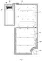
FIG 3 , thetop wall 41 of the heat-conductingmember 40 is provided with afirst groove 411 and asecond groove 412 respectively matching the outer shapes of therefrigerant pipe 20 and theheating wire 30, and a portion of therefrigerant pipe 20 is received in thefirst groove 411 and a portion of theheating wire 30 is received in thesecond groove 412. A portion of therefrigerant pipe 20 in contact with theice mold 10 is constructed in a U-shape, theheating wire 30 is also constructed in a U-shape, therefrigerant pipe 20 and theheating wire 30 are arranged oppositely, i.e., the two U-shapes open in opposite directions, and therefrigerant pipe 20 is located on an inner side of the U-shape of theheating wire 30. The ice-makingassembly 100 further comprises adriving mechanism 60 at an end of theice mold 10, and thedriving mechanism 60 is used to bring anice discharger 70 on theice mold 10 to rotate to perform deicing. An open end of the U-shape of theheating wire 30 faces towards the drivingmechanism 60 to facilitate making electrical connection. The open end of the U-shape of therefrigerant pipe 20 faces away from thedriving mechanism 60 to facilitate connection with the refrigeration pipeline. In order to accelerate the conduction of the cold, the heat-dissipatingribs 45 are arranged at positions corresponding to thefirst grooves 411, so that the heat-dissipatingribs 42 are closer to therefrigerant pipe 20, thereby facilitating the absorption of the cold of therefrigerant pipe 20, and thereby improving the refrigerating efficiency. The heat-conductingmember 40 is preferably made of a metal, such as an integrally-formed aluminum member. The heat-conductingmember 40 is convenient to manufacture and meanwhile has high heat conductivity. - In addition, in order to further improve the heat exchange efficiency between the
refrigerant pipe 20 and theice mold 10, thetop wall 41 of the heat-conductingmember 10 is further provided with aconvex portion 413 extending in a direction from one end to the other end of theice mold 10, theconvex portion 413 is in direct contact with the bottom of theice mold 10, theconvex portion 413 is located in an interior of the U-shape of the refrigerant pipe, and the heat-conductingmember 40 receives the cold on therefrigerant pipe 20 and further conducts the cold to theice mold 10 again through theconvex portion 413, thereby quickening the conduction of col and improving the ice-making efficiency. Furthermore, a surface of theconvex portion 413 facing the airflow chamber forms a groove 414, that is, a wall thickness of thetop wall 41 of the heat-conductingmember 10 is substantially uniform, so that the surface area in contact with the airflow can be increased, thereby improving the heat exchange efficiency. Therefrigerant pipe 20 is wrapped by theice mold 10 and the heat-conductingmember 40. Frost will be formed on a surface inside theairflow chamber 44 of the heat-conductingmember 40. As theheating wire 30 is activated to de-ice, the heat-conductingmember 40 meanwhile absorbs heat to melt the frost, and the water resulting from the melting of the frost flows to thebottom wall 42 directly along the surface inside theairflow chamber 44; in order to speed up water drainage, thebottom wall 42 may be arranged to be inclined downwards in a direction from one end of theice mold 10 connected to thedriving mechanism 60 to the other end, with an inclination angle α being in a range of about 0.5-2.5 degrees. Furthermore, thebottom wall 42 is inclined downwards in a front-rear direction, with an inclination angle β being in a range of 3-5 degrees. Thewater outlet 421 is disposed at an end of thebottom wall 42 away from thedriving mechanism 60 and at a rear end of theheat conducting member 40, i.e., at the lowest part of thebottom wall 42, so that the water resulting from the melting of the frost can be sufficiently drained. Furthermore, awater blocking edge 423 is provided at an end of thebottom wall 42 away from an end of thedriving mechanism 60 to prevent overflow when the water resulting from the melting of the frost is excessive. - Further referring to
FIG 2 andFIG 3 , thebottom cover 50 comprises afirst enclosing wall 51 and asecond enclosing wall 52 corresponding to the two side walls, wherein a snap-fittingprotrusion 511 is provided on one of each enclosing wall and the corresponding side wall, and a snap-fittingslot 431 is provided on the other of each enclosing wall and the corresponding side wall, and the heat-conductingmember 40 and thebottom cover 50 are fixedly connected via the snap-fittingprotrusion 511 and the snap-fittingslot 431. Preferably, in the present embodiment, three snap-fittingslots 431 are disposed at an interval on eachside wall 43 in an extension direction of theice mold 10 from one end to the other end, and thefirst enclosing wall 51 and thesecond enclosing wall 52 are respectively provided with snap-fittingprotrusions 511 corresponding to the snap-fittingslots 431. Upon mounting, it is only necessary to align the position the heat-conductingmember 40 with the position of thebottom cover 50, and press the heat-conductingmember 40 between thefirst enclosing wall 51 and thesecond enclosing wall 52, and mount the heat-conductingmember 40 in position with thebottom cover 50 when a snap-fitting sound is heard. Athermal insulation panel 55 may be disposed between thebottom cover 50 and the bottom wall of the heat-conductingmember 40 to insulate the heat transfer from the heat-conductingmember 40 to thebottom cover 50 and prevent frost from being formed on thebottom cover 50. - In the direction of the
bottom cover 50 from one end to the other end of theice mold 10, a protrudingrim 54 protruding upwards is disposed at both ends of thebottom cover 50. The heat-conductingmember 40 is snap-fitted between the two protrudingrims 54. Thefirst enclosing wall 51, thesecond enclosing wall 52 and the two protrudingrims 54 enable the accurate positioning of the heat-conductingmember 40 relative to thebottom cover 50 in two directions, so that the positioning and the fixing of the heat-conductingmember 40 is more reliable. - The ice-making
assembly 100 further comprises ahousing 15 fixed to theice mold 10, wherein thehousing 15 has afirst edge 151 and asecond edge 152 respectively corresponding to thefirst enclosing wall 51 and thesecond enclosing wall 52, alug 153 provided with a snap-fitting hook or hook slot extends from thefirst edge 151 and thesecond edge 152 respectively, the two enclosing walls are respectively provided with a hook slot or snap-fitting hook, and thebottom cover 50 and thehousing 15 are fixedly connected via the hook slot and snap-fitting hook. As such, the heat-conductingmember 40 may be maintained in a relatively fixed position, thereby enabling therefrigerant pipe 20 and theheating wire 30 to keep in contact with theice mold 10, so that the heat transfer is more reliable. In the present embodiment, preferably twolugs 153 extend downwards from thefirst edge 151 and thesecond edge 152, respectively, namely, twolugs 153 are provided at a front end of theice mold 10, twolugs 153 are provided at a rear end of theice mold 10, hook slots are provided on thelugs 153, and snap-fitting hooks are correspondingly provided on the two enclosingwalls ice guide 16 is fixedly connected to the front end of theice mold 10 to prevent falling ice cubes from hitting the snap-fitting hooks or the hook slots upon deicing. Theice guide 16 extends downwards to a position flush with the snap-fitting hooks. - The
housing 15 and theice mold 10 are integrally formed to simplify the installation of the entire ice-makingassembly 100. Thehousing 15 has a front end and an opposite rear end, the rear end of thehousing 15 forms an upwardly-extendingback plate 155, a mounting structure is provided on theback plate 155 for mounting the ice-makingassembly 100 inside the refrigerator, and thedriving mechanism 60 may be mounted on thehousing 15. As such, only thehousing 15 needs to be fixedly connected to the refrigerator, so the mounting is more convenient. In addition, one end of thehousing 15 away from thedriving mechanism 60 forms an upwardly-extendingend plate 156, awater filling trough 18 is disposed on an outer side of theend plate 156 relative to theice mold 10, a water filling port communicated with an inner cavity of theice mold 10 is disposed at a position of thewater filling trough 18 adjacent to theice mold 10, that is to say, the water filling trough is communicated with the ice cells. The water filling tough 18 and theice mold 10 are also integrally formed, thereby avoiding the problem of water leakage during the water filling process. - In the ice-making assembly according to the above-mentioned embodiment, it is not necessary to provide heat-dissipating fins at the bottom of the ice mold; upon mounting, it is only necessary to align parts in position and snap-fit the bottom cover relative to the ice mold; the ice mold may directly contact the refrigerant pipe and the heating wire under the action of the heat-conducting member, thereby reducing the mounting space of the ice maker and increasing the evaporation area of the refrigeration pipeline; furthermore, it is unnecessary to additionally provide the heating wire and the heating and heat-conducting member to melt the frost into water and drain the resultant water. The mounting is very convenient and the cost is lower.
- Referring to
FIG 5 , a refrigerator in an embodiment provided by the present invention comprises a cabinet 910, adoor body 920 movably connected to the cabinet and a refrigerating system, wherein the cabinet 910 defines a chilling compartment, a fan for introducing cold air into the chilling compartment is further provided in the cabinet, the chilling compartment comprises a refrigeratingchamber 91 and a freezingchamber 92, the refrigeratingchamber 91 and the freezingchamber 92 are provided from top to bottom, thedoor body 920 is used for opening and closing the refrigeratingchamber 91, either the refrigeratingchamber 91 or thedoor body 920 is provided with an ice-making chamber, and an ice-making assembly 100 (not shown) is provided in the ice-making chamber, anice bin 200 is provided below the ice-making assembly, a dispenser (not shown) selectively communicated with the ice-making chamber is provided on thedoor body 920, and ice cubes prepared by the ice-makingassembly 100 fall into theice bin 200 for storage and can be discharged from the dispenser. In the present embodiment, the ice-making chamber is preferably disposed on thedoor body 920 of the refrigerating chamber, and the chilling compartment comprises a freezing chamber and a refrigerating chamber, and certainly, the chilling compartment may comprise more chambers, such as a temperature variable chamber. - The refrigerating system comprises a
compressor 913 and a condenser connected to an outlet side of thecompressor 913, therefrigerant pipe 20 of the above-mentioned ice-makingassembly 100 is connected to the refrigerating system, thecompressor 913 is disposed at the bottom of the cabinet 910, anevaporator 912 for supplying cold to the freezingchamber 92 and the refrigeratingchamber 91 is disposed in a rear of the freezing chamber, and theevaporator 912 may be connected to both sides of the compressor and the condenser in series or in parallel with therefrigerant pipe 20 for supplying cold for the ice-making. Since the installation of theice making assembly 100 itself is more convenient, the overall assembling of the refrigerator is also more convenient, thereby reducing the manufacturing cost of the refrigerator. - It should be understood that although the description is described according to the embodiments, not every embodiment only includes one independent technical solution, that such a description manner is only for the sake of clarity, that those skilled in the art should take the description as an integral part, and that the technical solutions in the embodiments may be suitably combined to form other embodiments understandable by those skilled in the art.
- The detailed descriptions set forth above are merely specific illustrations of feasible embodiments of the present invention, and are not intended to limit the scope of protection of the present invention. All equivalent embodiments or modifications that do not depart from the art spirit of the present invention should fall within the scope of protection of the present invention.
Claims (11)
- An ice-making assembly, comprising:an ice mold having a plurality of ice cells for containing ice-making water;a refrigerant pipe extending from one end to the other end of the ice mold and located at a bottom of the ice mold;a heating wire located at the bottom of the ice mold and spaced apart from the refrigerant pipe;wherein the ice-making assembly further comprises a heat-conducting member and a bottom cover surrounding the outside of the heat-conducting member, the heat-conducting member is disposed between the ice mold and the bottom cover, the refrigerant pipe and the heating wire are positioned between the ice mold and the heat-conducting member, the heat-conducting member supports at least a portion of the refrigerant pipe and at least a portion of the heating wire such that the at least a portion of the refrigerant pipe and the at least a portion of the heating wire are in direct contact with the ice mold to transfer cold and heat to the ice mold;the heat-conducting member comprises a top wall adjacent to the ice mold, an opposite bottom wall and two side walls connecting the top wall with the bottom wall, where the top wall, the bottom wall and the two side walls enclose an airflow chamber which is through in a direction from one end to the other end of the ice mold, heat-dissipating ribs extending from the top wall to the bottom wall are provided in the airflow chamber, a water outlet is formed at an end of the bottom wall, the bottom cover surrounds the bottom wall and the two side walls, and the heat-conducting member is fixed relative to the ice mold via the bottom cover.
- The ice-making assembly according to claim 1, wherein the top wall is provided with a first groove and a second groove respectively matching outer shapes of the refrigerant pipe and the heating wire, a portion of the refrigerant pipe is received in the first groove, a portion of the heating wire is received in the second groove, and the heat-dissipating ribs are positioned corresponding to the first groove.
- The ice-making assembly according to claim 1, wherein the bottom cover comprises a first enclosing wall and a second enclosing wall corresponding to the two side walls, a snap-fitting protrusion is provided on one of each enclosing wall and the corresponding side wall, a snap-fitting slot is provided on the other of each enclosing wall and the corresponding side wall, and the heat-conducting member and the bottom cover are fixedly connected via the snap-fitting protrusion and the snap-fitting slot.
- The ice-making assembly according to claim 3, wherein the ice-making assembly further comprises a housing fixed to the ice mold, the housing has a first edge and a second edge respectively corresponding to the first enclosing wall and the second enclosing wall, a lug provided with a snap-fitting hook or hook slot extends from the first edge and the second edge respectively, the two enclosing walls are respectively provided with a hook slot or snap-fitting hook, and the bottom cover and the housing are fixedly connected via the hook slot and snap-fitting hook.
- The ice-making assembly according to claim 4, wherein an ice guide is fixedly connected to the front end of the ice mold, and the ice guide extends downwards to a position flush with the snap-fitting hook.
- The ice-making assembly according to claim 4, wherein the housing and the ice mold are integrally formed, the housing further comprises a back plate extending upwardly from an end perpendicular to an extension direction of the ice mold, and the ice-making assembly is mounted to an interior of the refrigerator by a mounting structure on the back plate.
- The ice-making assembly according to claim 1, wherein the refrigerant pipe is configured in a U-shape, the top wall is further provided with a convex portion extending in a direction from one end to the other of the ice mold, the convex portion is located in the interior of the U-shape of the refrigerant pipe, and the convex portion is in direct contact with the bottom of the ice mold.
- The ice-making assembly according to claim 1, wherein in a direction of the bottom cover from one end to the other end of the ice mold, a protruding rim protruding upwards is disposed at both ends of the bottom cover, and the heat-conducting member is snap-fitted between the two protruding rims.
- The ice-making assembly according to claim 1, wherein the ice-making assembly further comprises a driving mechanism connected to an end of the ice mold, the bottom wall is arranged to be inclined downwards in a direction from one end of the ice mold connected to the driving mechanism to the other end, and the bottom wall is inclined downwards in a front-rear direction.
- The ice-making assembly according to claim 9, wherein the ice-making assembly further comprises a housing fixed with the ice mold, one end of the housing away from the driving mechanism forms an upwardly-extending end plate, a water filling trough is disposed on an outer side of the end plate relative to the ice mold, the water filling trough is communicated with the ice cells, and the water filling tough, the ice mold and the housing are integrally formed.
- A refrigerator, comprising:a cabinet defining a refrigerating chamber and a freezing chamber;a door body movably connected to the cabinet and configured to open and close the refrigerating chamber;an ice-making chamber disposed in the door body;a refrigerating system comprising a compressor and a condenser connected to an outlet side of the compressor;wherein the ice-making assembly according to any one of claims 1-10 is disposed in the ice-making chamber, and the refrigerant pipe is connected to the refrigerating system.
Applications Claiming Priority (2)
| Application Number | Priority Date | Filing Date | Title |
|---|---|---|---|
| CN202110002179.4A CN114719513B (en) | 2021-01-04 | 2021-01-04 | Ice making assembly and refrigerator |
| PCT/CN2021/143523 WO2022143972A1 (en) | 2021-01-04 | 2021-12-31 | Ice making assembly and refrigerator |
Publications (2)
| Publication Number | Publication Date |
|---|---|
| EP4273472A1 true EP4273472A1 (en) | 2023-11-08 |
| EP4273472A4 EP4273472A4 (en) | 2024-06-26 |
Family
ID=82234163
Family Applications (1)
| Application Number | Title | Priority Date | Filing Date |
|---|---|---|---|
| EP21914701.4A Pending EP4273472A4 (en) | 2021-01-04 | 2021-12-31 | ICE MAKING ARRANGEMENT AND REFRIGERATOR |
Country Status (3)
| Country | Link |
|---|---|
| EP (1) | EP4273472A4 (en) |
| CN (1) | CN114719513B (en) |
| WO (1) | WO2022143972A1 (en) |
Families Citing this family (2)
| Publication number | Priority date | Publication date | Assignee | Title |
|---|---|---|---|---|
| CN117053449A (en) * | 2023-08-24 | 2023-11-14 | 滁州市阿依斯梅克制冷科技有限公司 | A spherical ice-making core that can be used at room temperature |
| CN119097039A (en) * | 2024-08-29 | 2024-12-10 | 广州新岸贸易有限公司 | Water receiving mechanism for cold drink machine and cold drink machine |
Family Cites Families (11)
| Publication number | Priority date | Publication date | Assignee | Title |
|---|---|---|---|---|
| TW200519338A (en) * | 2003-10-23 | 2005-06-16 | Matsushita Electric Industrial Co Ltd | Ice tray and ice making machine, refrigerator both using the ice tray |
| JP2007278662A (en) * | 2006-04-11 | 2007-10-25 | Matsushita Electric Ind Co Ltd | Ice tray |
| KR101613415B1 (en) * | 2010-01-04 | 2016-04-20 | 삼성전자 주식회사 | Ice maker and refrigerator having the same |
| KR20160088777A (en) * | 2015-01-16 | 2016-07-26 | 주식회사 대창 | Ice maker |
| CN205066277U (en) * | 2015-08-07 | 2016-03-02 | 孟海 | Ice making machine |
| CN205580041U (en) * | 2016-02-01 | 2016-09-14 | 中山东菱威力电器有限公司 | Flowing water ice evaporate ware |
| US11079152B2 (en) * | 2017-07-07 | 2021-08-03 | Bsh Home Appliances Corporation | Control logic for compact ice making system |
| KR102435200B1 (en) * | 2017-09-29 | 2022-08-24 | 삼성전자주식회사 | Refrigerator |
| US10605511B2 (en) * | 2018-05-02 | 2020-03-31 | Bsh Home Appliances Corporation | Clear ice maker assembly for producing clear ice for refrigerator appliance |
| KR102742577B1 (en) * | 2019-03-20 | 2024-12-13 | 주식회사 대창 | Ice maker and refrigerator incuding the same |
| CN110440504B (en) * | 2019-09-03 | 2024-04-19 | 海信容声(广东)冰箱有限公司 | Refrigerator with a refrigerator body |
-
2021
- 2021-01-04 CN CN202110002179.4A patent/CN114719513B/en active Active
- 2021-12-31 WO PCT/CN2021/143523 patent/WO2022143972A1/en not_active Ceased
- 2021-12-31 EP EP21914701.4A patent/EP4273472A4/en active Pending
Also Published As
| Publication number | Publication date |
|---|---|
| WO2022143972A1 (en) | 2022-07-07 |
| CN114719513A (en) | 2022-07-08 |
| CN114719513B (en) | 2023-06-16 |
| EP4273472A4 (en) | 2024-06-26 |
Similar Documents
| Publication | Publication Date | Title |
|---|---|---|
| KR20190071427A (en) | Ice maker and refrigerator including the same | |
| KR20160148282A (en) | Refrigerator and method for assembling ice maker of refrigerator | |
| EP4273472A1 (en) | Ice making assembly and refrigerator | |
| EP4276389B1 (en) | Ice-making assembly and refrigerator with it | |
| JP2000018800A (en) | Structure of refrigerator evaporating dish | |
| EP4273474A1 (en) | Ice-making assembly and refrigerator | |
| CN214581959U (en) | Ice-making unit and refrigerating and freezing device with same | |
| EP4273473A1 (en) | Ice making assembly and refrigerator | |
| US10267553B2 (en) | Household refrigerator with an icemaker unit and a cooling device having a pressure chamber for cooling the icemaker unit | |
| CN210772966U (en) | A kind of refrigerator | |
| EP4435354A1 (en) | Refrigerator | |
| CN115031457A (en) | Ice maker and refrigeration equipment | |
| CN218410367U (en) | Ice making assembly and refrigeration equipment | |
| CN218410364U (en) | Ice maker and refrigeration equipment | |
| CN221259214U (en) | Defrosting assembly, air duct assembly and refrigeration equipment | |
| CN218410368U (en) | Ice making assembly and refrigeration equipment | |
| CN221858943U (en) | refrigerator | |
| CN220206106U (en) | Evaporator, refrigerating device and refrigerating equipment | |
| CN115218584A (en) | Refrigerating and freezing device | |
| AU2022391851B2 (en) | Refrigerator and refrigerator manufacturing method | |
| CN221259211U (en) | Air duct assembly and refrigeration equipment | |
| CN221802196U (en) | Air duct assembly, box liner assembly and refrigeration equipment | |
| CN218410365U (en) | Heat preservation cover of ice making assembly, ice making assembly and refrigeration equipment | |
| CN221802198U (en) | Drainage assembly, air duct assembly and refrigeration equipment | |
| CN219913597U (en) | refrigerator |
Legal Events
| Date | Code | Title | Description |
|---|---|---|---|
| STAA | Information on the status of an ep patent application or granted ep patent |
Free format text: STATUS: THE INTERNATIONAL PUBLICATION HAS BEEN MADE |
|
| PUAI | Public reference made under article 153(3) epc to a published international application that has entered the european phase |
Free format text: ORIGINAL CODE: 0009012 |
|
| STAA | Information on the status of an ep patent application or granted ep patent |
Free format text: STATUS: REQUEST FOR EXAMINATION WAS MADE |
|
| 17P | Request for examination filed |
Effective date: 20230706 |
|
| AK | Designated contracting states |
Kind code of ref document: A1 Designated state(s): AL AT BE BG CH CY CZ DE DK EE ES FI FR GB GR HR HU IE IS IT LI LT LU LV MC MK MT NL NO PL PT RO RS SE SI SK SM TR |
|
| DAV | Request for validation of the european patent (deleted) | ||
| DAX | Request for extension of the european patent (deleted) | ||
| REG | Reference to a national code |
Ref country code: DE Ref legal event code: R079 Free format text: PREVIOUS MAIN CLASS: F25C0001240000 Ipc: F25C0001040000 |
|
| A4 | Supplementary search report drawn up and despatched |
Effective date: 20240527 |
|
| RIC1 | Information provided on ipc code assigned before grant |
Ipc: F25C 5/08 20060101ALI20240521BHEP Ipc: F25C 1/04 20180101AFI20240521BHEP |