EP4273463A1 - Indoor unit for air conditioner - Google Patents
Indoor unit for air conditioner Download PDFInfo
- Publication number
- EP4273463A1 EP4273463A1 EP21926703.6A EP21926703A EP4273463A1 EP 4273463 A1 EP4273463 A1 EP 4273463A1 EP 21926703 A EP21926703 A EP 21926703A EP 4273463 A1 EP4273463 A1 EP 4273463A1
- Authority
- EP
- European Patent Office
- Prior art keywords
- indoor unit
- space
- flap
- air conditioner
- fan
- Prior art date
- Legal status (The legal status is an assumption and is not a legal conclusion. Google has not performed a legal analysis and makes no representation as to the accuracy of the status listed.)
- Granted
Links
Images





Classifications
-
- F—MECHANICAL ENGINEERING; LIGHTING; HEATING; WEAPONS; BLASTING
- F24—HEATING; RANGES; VENTILATING
- F24F—AIR-CONDITIONING; AIR-HUMIDIFICATION; VENTILATION; USE OF AIR CURRENTS FOR SCREENING
- F24F1/00—Room units for air-conditioning, e.g. separate or self-contained units or units receiving primary air from a central station
- F24F1/0007—Indoor units, e.g. fan coil units
- F24F1/0071—Indoor units, e.g. fan coil units with means for purifying supplied air
-
- F—MECHANICAL ENGINEERING; LIGHTING; HEATING; WEAPONS; BLASTING
- F24—HEATING; RANGES; VENTILATING
- F24F—AIR-CONDITIONING; AIR-HUMIDIFICATION; VENTILATION; USE OF AIR CURRENTS FOR SCREENING
- F24F11/00—Control or safety arrangements
- F24F11/50—Control or safety arrangements characterised by user interfaces or communication
- F24F11/61—Control or safety arrangements characterised by user interfaces or communication using timers
-
- F—MECHANICAL ENGINEERING; LIGHTING; HEATING; WEAPONS; BLASTING
- F24—HEATING; RANGES; VENTILATING
- F24F—AIR-CONDITIONING; AIR-HUMIDIFICATION; VENTILATION; USE OF AIR CURRENTS FOR SCREENING
- F24F11/00—Control or safety arrangements
- F24F11/62—Control or safety arrangements characterised by the type of control or by internal processing, e.g. using fuzzy logic, adaptive control or estimation of values
- F24F11/63—Electronic processing
- F24F11/64—Electronic processing using pre-stored data
-
- F—MECHANICAL ENGINEERING; LIGHTING; HEATING; WEAPONS; BLASTING
- F24—HEATING; RANGES; VENTILATING
- F24F—AIR-CONDITIONING; AIR-HUMIDIFICATION; VENTILATION; USE OF AIR CURRENTS FOR SCREENING
- F24F11/00—Control or safety arrangements
- F24F11/70—Control systems characterised by their outputs; Constructional details thereof
- F24F11/72—Control systems characterised by their outputs; Constructional details thereof for controlling the supply of treated air, e.g. its pressure
- F24F11/74—Control systems characterised by their outputs; Constructional details thereof for controlling the supply of treated air, e.g. its pressure for controlling air flow rate or air velocity
-
- F—MECHANICAL ENGINEERING; LIGHTING; HEATING; WEAPONS; BLASTING
- F24—HEATING; RANGES; VENTILATING
- F24F—AIR-CONDITIONING; AIR-HUMIDIFICATION; VENTILATION; USE OF AIR CURRENTS FOR SCREENING
- F24F11/00—Control or safety arrangements
- F24F11/70—Control systems characterised by their outputs; Constructional details thereof
- F24F11/72—Control systems characterised by their outputs; Constructional details thereof for controlling the supply of treated air, e.g. its pressure
- F24F11/79—Control systems characterised by their outputs; Constructional details thereof for controlling the supply of treated air, e.g. its pressure for controlling the direction of the supplied air
-
- F—MECHANICAL ENGINEERING; LIGHTING; HEATING; WEAPONS; BLASTING
- F24—HEATING; RANGES; VENTILATING
- F24F—AIR-CONDITIONING; AIR-HUMIDIFICATION; VENTILATION; USE OF AIR CURRENTS FOR SCREENING
- F24F13/00—Details common to, or for air-conditioning, air-humidification, ventilation or use of air currents for screening
- F24F13/08—Air-flow control members, e.g. louvres, grilles, flaps or guide plates
- F24F13/10—Air-flow control members, e.g. louvres, grilles, flaps or guide plates movable, e.g. dampers
- F24F13/14—Air-flow control members, e.g. louvres, grilles, flaps or guide plates movable, e.g. dampers built up of tilting members, e.g. louvre
-
- F—MECHANICAL ENGINEERING; LIGHTING; HEATING; WEAPONS; BLASTING
- F24—HEATING; RANGES; VENTILATING
- F24F—AIR-CONDITIONING; AIR-HUMIDIFICATION; VENTILATION; USE OF AIR CURRENTS FOR SCREENING
- F24F8/00—Treatment, e.g. purification, of air supplied to human living or working spaces otherwise than by heating, cooling, humidifying or drying
- F24F8/20—Treatment, e.g. purification, of air supplied to human living or working spaces otherwise than by heating, cooling, humidifying or drying by sterilisation
- F24F8/24—Treatment, e.g. purification, of air supplied to human living or working spaces otherwise than by heating, cooling, humidifying or drying by sterilisation using sterilising media
- F24F8/26—Treatment, e.g. purification, of air supplied to human living or working spaces otherwise than by heating, cooling, humidifying or drying by sterilisation using sterilising media using ozone
-
- F—MECHANICAL ENGINEERING; LIGHTING; HEATING; WEAPONS; BLASTING
- F24—HEATING; RANGES; VENTILATING
- F24F—AIR-CONDITIONING; AIR-HUMIDIFICATION; VENTILATION; USE OF AIR CURRENTS FOR SCREENING
- F24F2110/00—Control inputs relating to air properties
- F24F2110/20—Humidity
-
- F—MECHANICAL ENGINEERING; LIGHTING; HEATING; WEAPONS; BLASTING
- F24—HEATING; RANGES; VENTILATING
- F24F—AIR-CONDITIONING; AIR-HUMIDIFICATION; VENTILATION; USE OF AIR CURRENTS FOR SCREENING
- F24F8/00—Treatment, e.g. purification, of air supplied to human living or working spaces otherwise than by heating, cooling, humidifying or drying
- F24F8/40—Treatment, e.g. purification, of air supplied to human living or working spaces otherwise than by heating, cooling, humidifying or drying by ozonisation
Definitions
- the present disclosure relates to an indoor unit for an air conditioner.
- bacteria mixed in air sucked in during a cooling operation may adhere to the interior of the indoor unit.
- the dew condensation water facilitates breeding of bacteria.
- bacteria breed it causes a stain or an odor. Therefore, it is required to suppress the breeding of bacteria.
- PTL 1 discloses a method using ozone. According to this method, after a cooling operation is stopped, sterilization treatment is performed by generating OH radicals by generating ozone in a state where a discharge outlet is closed, and then the wet interior of the indoor unit is dried by a heating operation.
- the present disclosure has been made in view of such circumstances, and has an object to provide an indoor unit for an air conditioner in which it is possible to prevent the interior of the indoor unit from being in a high humidity state for a long period of time.
- an indoor unit for an air conditioner of the present disclosure adopts the following means.
- an indoor unit for an air conditioner includes: a housing having a space formed inside, and a discharge outlet making the space communicate with an outside; a flap that opens and closes the discharge outlet; an ozone generator provided in the space; and a control unit, the control unit causing the ozone generator to generate ozone in an open state where the flap does not close the discharge outlet, after a cooling operation or a dehumidification operation is stopped.
- the indoor unit for an air conditioner it is possible to prevent the interior of the indoor unit from being in a high humidity state for a long period of time.
- a wall-mounted type indoor unit will be described as an example.
- the type of the indoor unit is not limited to the wall-mounted type, and other types of indoor units can also be applied.
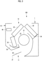
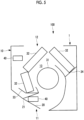
- FIG. 1 Side sectional views of an indoor unit 1 for an air conditioner 100 are shown in Figs. 1 to 4 .
- the air conditioner 100 includes the indoor unit 1 that is installed indoors and an outdoor unit (not shown) that is installed outdoors.
- the indoor unit 1 and the outdoor unit are connected by a refrigerant pipe or the like (not shown).
- the indoor unit 1 includes a housing 10, a flap 20, a fan 31, a heat exchanger 32, and an ozone generator 40.
- a space 13 is formed inside the housing 10.
- the fan 31, the heat exchanger 32, and the ozone generator 40 are accommodated in the space 13.
- a discharge outlet 11 is provided in a lower portion of the housing 10.
- the discharge outlet 11 makes the space 13 communicate with the outside (the room inside) of the housing 10.
- the discharge outlet 11 is an opening for blowing out temperature-adjusted air into the room.
- a suction port 12 is provided in an upper portion (ceiling portion) of the housing 10.
- the suction port 12 makes the space 13 communicate with the outside (the room inside) of the housing 10.
- the suction port 12 is an opening for taking in air in the room before temperature adjustment into the space 13.
- the flap 20 is a plate-like component provided in the discharge outlet 11. As shown in Figs. 1 to 4 , the flap 20 is configured to move between a closed-state position ( Fig. 1 ) in which the discharge outlet 11 is closed and an open-state position ( Figs. 2 to 4 ) in which the discharge outlet 11 is opened without being closed.
- the closed-state position in which the discharge outlet 11 is closed refers to, for example, a state where the housing 10 and a tip portion 21 of the flap 20 are smoothly substantially flush with each other, as shown in Fig. 1 .
- the tip portion 21 of the flap 20 is an end portion that is located on the upstream side in a direction in which air is blown out.
- the fan 31 is a cylindrical cross-flow fan.
- the fan 31 extends in a direction perpendicular to the plane of the paper of the drawing.
- the fan 31 is driven by a motor (not shown).
- the heat exchanger 32 is provided so as to surround the fan 31 from the outer periphery.
- the heat exchanger 32 is of, for example, a plate-fin tube type.
- Drain pans 33 and 34 are provided below the heat exchangers 32 to receive water droplets generated due to heat exchange.
- a flow of air is generated by the rotation of the fan 31, and the air is taken into the space 13 through the suction port 12.
- the air taken in through the suction port 12 is supplied to the heat exchanger 32.
- the air heat-exchanged in the heat exchanger 32 is blown out from the discharge outlet 11 to the outside (the room inside) of the housing 10.
- the ozone generator 40 is a device that generates ozone in the space 13.
- the ozone generator 40 is of, for example, an electric discharge type.
- the ozone generator 40 is provided, for example, on the front surface side of the housing 10 in the space 13.
- ozone generators 40 The installation locations or the number of ozone generators 40 is not limited to that shown in Figs. 1 to 4 .
- two ozone generators 40 may be provided, and the ozone generator 40 may be installed in the vicinity of the discharge outlet 11.
- the indoor unit 1 configured as described above is appropriately controlled by a control unit (not shown) and operated in various operation modes (cooling, dehumidification, air blowing, heating, and the like).
- control unit is composed of, for example, a CPU (Central Processing Unit), a RAM (Random Access Memory), a ROM (Read Only Memory), a computer-readable storage medium, and the like.
- CPU Central Processing Unit
- RAM Random Access Memory
- ROM Read Only Memory
- a series of processing for realizing various functions is stored in a storage medium or the like in the form of a program, as an example, and the CPU reads out this program to a RAM or the like, and executes processing for information processing and calculation, whereby various functions are realized.
- a form installed in advance in a ROM or other storage medium a form of being provided in a state where it is stored in a computer-readable storage medium, a form of being delivered via wired or wireless communication means, or the like may be applied.
- the computer-readable storage media is a magnetic disk, a magneto-optical disk, a CD-ROMs, a DVD-ROMs, a semiconductor memory, or the like.
- Sterilization with ozone in a dry state is generally well known.
- the sterilization effect is improved by dissolving ozone in water and then drying it. This is considered to be due to the following factors. That is, water and ozone come into contact with each other, so that OH radicals having stronger oxidizing power than ozone are generated, and these OH radicals exhibit a strong sterilization effect.
- the indoor unit 1 can perform the sterilization treatment as described above after a cooling operation or a dehumidification operation is stopped. Control of each device related to the sterilization treatment is performed by a control unit (not shown).
- After stopping of the cooling operation or the dehumidification operation refers to, for example, a state where a compressor (not shown) is stopped and the flap 20 is moved to the closed-state position.
- the ozone generator 40 After the cooling operation or the dehumidification operation is stopped, the ozone generator 40 generates ozone to dissolve the ozone in the dew condensation water. At this time, OH radicals having stronger oxidizing power than the ozone are generated due to the contact between the dew condensation water and the ozone. Then, the amount of dew condensation water decreases as the drying progresses, and the number of remaining bacteria also decreases.
- ozone is generated (that is, the ozone generator 40 is started) while drying the space 13.
- This method can prevent the space 13 from being in a high humidity state for a long period of time and increase the concentration of OH radicals dissolved in the dew condensation water in a short time.
- Drying of the space 13 is started by opening at least the flap 20 regardless of whether or not the fan 31 blows air.
- the fan 31 may be driven at the same time as the starting of the ozone generator 40. In this way, it is possible to further promote drying of the space 13.
- FIG. 7 A difference in the amount of dew condensation reduction according to the state of the flap 20 in the relationship between the amount of dew condensation and time in a case where the fan 31 is driven is shown in Fig. 7 . According to this, it can be seen that drying is promoted in a case where the flap 20 is in an open state (indicated by a solid line), as compared to a case where the flap 20 is in a closed state (indicated by a dashed-dotted line).
- the fan 31 may be driven when a predetermined time (a first predetermined time) has elapsed after starting of the ozone generator 40. In this way, it is possible to take a sufficient time for the ozone to dissolve in the dew condensation water. Since the discharge outlet 11 is in an open state, drying of the space 13 is also performed between the starting of the ozone generator 40 and the driving of the fan 31.
- a predetermined time a first predetermined time
- the first predetermined time is a time obtained by a test conducted in advance, and is, for example, a time in a range of 30 to 60 minutes.
- the flap 20 is located within an allowable range of the flap 20 during a normal cooling operation or dehumidification operation while the space 13 is dried. In this way, it is possible to effectively perform drying. In particular, drying can be most efficiently performed by locating the flap 20 at its maximum air volume position (refer to Fig. 3 ) during a normal cooling operation or dehumidification operation.
- the flap 20 may be located on the side (the side close to the state in Fig. 1 ) where the discharge outlet 11 is closed outside the allowable range of the flap 20 during a normal cooling operation or dehumidification operation. In this way, the possibility that the humid air coming out of the discharge outlet 11 during the sterilization treatment may hit against the user can be reduced.
- the sterilization treatment started as described above is ended, for example, as follows.
- the sterilization treatment is stopped when a predetermined time (a second predetermined time) has elapsed after start of the sterilization treatment.
- stopping of the sterilization treatment refers to stopping of the ozone generator 40 or stopping of the fan 31. In this way, it is possible to stop the sterilization treatment with simple control.
- the second predetermined time is a time obtained by a test conducted in advance, and is a time during which the space 13 can be sufficiently dried.
- the second predetermined time is, for example, a time in a range of 60 to 120 minutes.
- the sterilization treatment is stopped when the difference in humidity between the sucked air and the blown air becomes substantially the same value. In this way, it is possible to stop the sterilization treatment after it is confirmed that the space 13 is surely dried.
- the humidity of the sucked air and the humidity of the blown air are measured as follows.
- a humidity sensor (a first humidity sensor 51) is provided in the vicinity of the discharge outlet 11 or in the space 13 on the downstream side with respect to the heat exchanger 32 in the air flow direction. Further, another humidity sensor (a second humidity sensor 52) is provided in the vicinity of the suction port 12 and in the space 13 on the upstream side with respect to the heat exchanger 32. In this way, it is possible to measure the humidity of the sucked air and the humidity of the blown air.
- the control unit causes the ozone generator 40 to generate ozone in the open state where the flap 20 does not close the discharge outlet 11 after the cooling operation or the dehumidification operation is stopped, the ozone can be dissolved in the dew condensation water generated in the space 13 to generate OH radicals, and at the same time, drying of the space 13 can be started.
- the fan 31 is driven when the first predetermined time has elapsed after starting of the ozone generator 40, it is possible to take a sufficient time for ozone to dissolve in the dew condensation water. Since the discharge outlet 11 is in an open state, drying of the space 13 is performed between the starting of the ozone generator 40 and the driving of the fan 31.
- stopping of the sterilization treatment can be controlled based on a time. In this way, it is possible to stop the sterilization treatment with simple control.
- the fan 31 is stopped when the measurement value of the first humidity sensor 51 and the measurement value of the second humidity sensor 52 become substantially the same value after the fan 31 is driven, it is possible to stop the sterilization treatment, based on the difference in humidity between the sucked air and the blown air. In this way, it is possible to stop the sterilization treatment after it is confirmed that the space 13 is surely dried.
- the inside (the space 13) of the housing 10 and the outside (the room inside) of the housing 10 communicate with each other with a sufficient area through the discharge outlet 11. In this way, it is possible to efficiently perform drying of the space 13. In particular, in a case where the flap is at its maximum air volume position during the cooling operation or the dehumidification operation, it is possible to most efficiently perform drying of the space 13.
- the possibility that the humid air coming out of the discharge outlet 11 during the sterilization treatment may hit against the user can be reduced.
- an indoor unit (1) for an air conditioner (100) includes: a housing (10) having a space (13) formed inside, and a discharge outlet (11) making the space communicate with the outside; a flap (20) that opens and closes the discharge outlet; an ozone generator (40) provided in the space; and a control unit, in which the control unit causes the ozone generator to generate ozone in an open state where the flap does not close the discharge outlet, after a cooling operation or a dehumidification operation is stopped.
- the control unit causes the ozone generator to generate ozone in the open state where the flap does not close the discharge outlet after the cooling operation or the dehumidification operation is stopped, the ozone can be dissolved in the dew condensation water generated in the space to generate OH radicals, and at the same time, drying of the space can be started.
- the control unit causes the ozone generator to generate ozone in the open state where the flap does not close the discharge outlet after the cooling operation or the dehumidification operation is stopped
- the ozone can be dissolved in the dew condensation water generated in the space to generate OH radicals, and at the same time, drying of the space can be started.
- the indoor unit for an air conditioner further includes a fan (31) provided in the space and sending air to the discharge outlet, in which the control unit drives the fan at the same time as starting of the ozone generator.
- the control unit drives the fan at the same time as starting of the ozone generator, it is possible to promote drying of the space.
- the indoor unit for an air conditioner further includes a fan provided in the space and sending air to the discharge outlet, in which the control unit drives the fan when a first predetermined time has elapsed after starting of the ozone generator.
- the control unit drives fan when the first predetermined time has elapsed after starting of the ozone generator, it is possible to take a sufficient time for ozone to dissolve in the dew condensation water. Since the discharge outlet is in an open state, drying of the space is performed between the starting of the ozone generator and the driving of the fan.
- control unit stops the fan when a second predetermined time has elapsed after driving of the fan.
- the control unit stops the fan when the second predetermined time has elapsed after driving of the fan, the stop of the sterilization treatment can be controlled based on a time. In this way, it is possible to stop the sterilization treatment with simple control.
- the housing has a suction port (12) that makes the space communicate with the outside
- the indoor unit further includes a first humidity sensor(51) provided in the space in the vicinity of the discharge outlet, and a second humidity sensor (52) provided in the space in the vicinity of the suction port, and the control unit stops the fan when a measurement value of the first humidity sensor and a measurement value of the second humidity sensor become substantially the same value after the fan is driven.
- the control unit stops the fan when the measurement value of the first humidity sensor and the measurement value of the second humidity sensor become substantially the same value after the fan is driven, it is possible to stop the sterilization treatment, based on the difference in humidity between the sucked air and the blown air. In this way, it is possible to stop the sterilization treatment after it is confirmed that the space is surely dried.
- the flap that is in an open state is located within an allowable range of the flap during the cooling operation or the dehumidification operation.
- the inside (the space) of the housing and the outside (the room inside) of the housing communicate with each other with a sufficient area through the discharge outlet. In this way, it is possible to efficiently perform drying of the space.
- the flap that is in an open state is at its maximum air volume position during the cooling operation or the dehumidification operation.
- the flap that is in an open state is at its maximum air volume position during the cooling operation or the dehumidification operation, it is possible to most efficiently perform drying of the space.
- the flap that is in an open state is located on the side where the discharge outlet is closed outside an allowable range of the flap during the cooling operation or the dehumidification operation.
- the flap that is in an open state is located on the side where the discharge outlet is closed outside the allowable range of the flap during the cooling operation or the dehumidification operation, the possibility that the humid air coming out of the discharge outlet during the sterilization treatment may hit against the user can be reduced.
Landscapes
- Engineering & Computer Science (AREA)
- Combustion & Propulsion (AREA)
- Mechanical Engineering (AREA)
- General Engineering & Computer Science (AREA)
- Chemical & Material Sciences (AREA)
- Signal Processing (AREA)
- Physics & Mathematics (AREA)
- Fluid Mechanics (AREA)
- Fuzzy Systems (AREA)
- Mathematical Physics (AREA)
- Human Computer Interaction (AREA)
- Air Filters, Heat-Exchange Apparatuses, And Housings Of Air-Conditioning Units (AREA)
- Air Conditioning Control Device (AREA)
- Devices For Blowing Cold Air, Devices For Blowing Warm Air, And Means For Preventing Water Condensation In Air Conditioning Units (AREA)
Abstract
Description
- The present disclosure relates to an indoor unit for an air conditioner.
- In an indoor unit for an air conditioner, bacteria mixed in air sucked in during a cooling operation may adhere to the interior of the indoor unit. In a case where dew condensation water is generated inside the indoor unit due to the cooling operation, the dew condensation water facilitates breeding of bacteria. In a case where bacteria breed, it causes a stain or an odor. Therefore, it is required to suppress the breeding of bacteria.
- As a method for suppressing the breeding of bacteria, for example,
PTL 1 discloses a method using ozone. According to this method, after a cooling operation is stopped, sterilization treatment is performed by generating OH radicals by generating ozone in a state where a discharge outlet is closed, and then the wet interior of the indoor unit is dried by a heating operation. - [PTL 1]
Japanese Unexamined Patent Application Publication No. 2008-111623 - However, in the method of
PTL 1, since it takes time to start drying, the interior of the indoor unit remains in a high humidity state for a long period of time, which is not preferable in terms of the purpose of suppressing the breeding of bacteria. - The present disclosure has been made in view of such circumstances, and has an object to provide an indoor unit for an air conditioner in which it is possible to prevent the interior of the indoor unit from being in a high humidity state for a long period of time.
- In order to solve the above problem, an indoor unit for an air conditioner of the present disclosure adopts the following means.
- That is, an indoor unit for an air conditioner according to an aspect of the present disclosure includes: a housing having a space formed inside, and a discharge outlet making the space communicate with an outside; a flap that opens and closes the discharge outlet; an ozone generator provided in the space; and a control unit, the control unit causing the ozone generator to generate ozone in an open state where the flap does not close the discharge outlet, after a cooling operation or a dehumidification operation is stopped.
- According to the indoor unit for an air conditioner according to the present disclosure, it is possible to prevent the interior of the indoor unit from being in a high humidity state for a long period of time.
-
-
Fig. 1 is a side sectional view of an indoor unit for an air conditioner. -
Fig. 2 is a side sectional view of the indoor unit for an air conditioner. -
Fig. 3 is a side sectional view of the indoor unit for an air conditioner. -
Fig. 4 is a side sectional view of the indoor unit for an air conditioner. -
Fig. 5 is a side sectional view of the indoor unit for an air conditioner. -
Fig. 6 is a diagram showing the relationship between the amount of dew condensation, the number of remaining bacteria, and time. -
Fig. 7 is a diagram showing a difference in the amount of dew condensation reduction according to the state of the flap in the relationship between the amount of dew condensation and time. - Hereinafter, an indoor unit for an air conditioner according to an embodiment of the present disclosure will be described with reference to the drawings.
- In the present embodiment, a wall-mounted type indoor unit will be described as an example. However, the type of the indoor unit is not limited to the wall-mounted type, and other types of indoor units can also be applied.
- Side sectional views of an
indoor unit 1 for anair conditioner 100 are shown inFigs. 1 to 4 . - The
air conditioner 100 includes theindoor unit 1 that is installed indoors and an outdoor unit (not shown) that is installed outdoors. Theindoor unit 1 and the outdoor unit are connected by a refrigerant pipe or the like (not shown). - The
indoor unit 1 includes ahousing 10, aflap 20, afan 31, aheat exchanger 32, and anozone generator 40. - A
space 13 is formed inside thehousing 10. Thefan 31, theheat exchanger 32, and theozone generator 40 are accommodated in thespace 13. - A
discharge outlet 11 is provided in a lower portion of thehousing 10. Thedischarge outlet 11 makes thespace 13 communicate with the outside (the room inside) of thehousing 10. Thedischarge outlet 11 is an opening for blowing out temperature-adjusted air into the room. - A
suction port 12 is provided in an upper portion (ceiling portion) of thehousing 10. Thesuction port 12 makes thespace 13 communicate with the outside (the room inside) of thehousing 10. Thesuction port 12 is an opening for taking in air in the room before temperature adjustment into thespace 13. - The
flap 20 is a plate-like component provided in thedischarge outlet 11. As shown inFigs. 1 to 4 , theflap 20 is configured to move between a closed-state position (Fig. 1 ) in which thedischarge outlet 11 is closed and an open-state position (Figs. 2 to 4 ) in which thedischarge outlet 11 is opened without being closed. - The closed-state position in which the
discharge outlet 11 is closed refers to, for example, a state where thehousing 10 and atip portion 21 of theflap 20 are smoothly substantially flush with each other, as shown inFig. 1 . Thetip portion 21 of theflap 20 is an end portion that is located on the upstream side in a direction in which air is blown out. - Even if there is an unavoidable gap (opening) between the
housing 10 and theflap 20, if theflap 20 is at a limit position of closing thedischarge outlet 11 from a mechanical point of view, it is in the closed-state position. - The
fan 31 is a cylindrical cross-flow fan. Thefan 31 extends in a direction perpendicular to the plane of the paper of the drawing. Thefan 31 is driven by a motor (not shown). - The
heat exchanger 32 is provided so as to surround thefan 31 from the outer periphery. Theheat exchanger 32 is of, for example, a plate-fin tube type. - Drain
pans heat exchangers 32 to receive water droplets generated due to heat exchange. - A flow of air is generated by the rotation of the
fan 31, and the air is taken into thespace 13 through thesuction port 12. The air taken in through thesuction port 12 is supplied to theheat exchanger 32. The air heat-exchanged in theheat exchanger 32 is blown out from thedischarge outlet 11 to the outside (the room inside) of thehousing 10. - The
ozone generator 40 is a device that generates ozone in thespace 13. Theozone generator 40 is of, for example, an electric discharge type. Theozone generator 40 is provided, for example, on the front surface side of thehousing 10 in thespace 13. - The installation locations or the number of
ozone generators 40 is not limited to that shown inFigs. 1 to 4 . For example, as shown inFig. 5 , twoozone generators 40 may be provided, and theozone generator 40 may be installed in the vicinity of thedischarge outlet 11. - The
indoor unit 1 configured as described above is appropriately controlled by a control unit (not shown) and operated in various operation modes (cooling, dehumidification, air blowing, heating, and the like). - Here, the control unit is composed of, for example, a CPU (Central Processing Unit), a RAM (Random Access Memory), a ROM (Read Only Memory), a computer-readable storage medium, and the like.
- Then, a series of processing for realizing various functions is stored in a storage medium or the like in the form of a program, as an example, and the CPU reads out this program to a RAM or the like, and executes processing for information processing and calculation, whereby various functions are realized.
- As the program, a form installed in advance in a ROM or other storage medium, a form of being provided in a state where it is stored in a computer-readable storage medium, a form of being delivered via wired or wireless communication means, or the like may be applied.
- The computer-readable storage media is a magnetic disk, a magneto-optical disk, a CD-ROMs, a DVD-ROMs, a semiconductor memory, or the like.
- Sterilization with ozone in a dry state is generally well known.
- Further, it has been found that the sterilization effect is improved by dissolving ozone in water and then drying it. This is considered to be due to the following factors. That is, water and ozone come into contact with each other, so that OH radicals having stronger oxidizing power than ozone are generated, and these OH radicals exhibit a strong sterilization effect.
- The
indoor unit 1 can perform the sterilization treatment as described above after a cooling operation or a dehumidification operation is stopped. Control of each device related to the sterilization treatment is performed by a control unit (not shown). - After stopping of the cooling operation or the dehumidification operation refers to, for example, a state where a compressor (not shown) is stopped and the
flap 20 is moved to the closed-state position. - The relationship between the amount of dew condensation present in the
space 13 after the cooling operation or the dehumidification operation is stopped, the number of remaining bacteria, and time is shown inFig. 6 . - As shown in
Fig. 6 , a certain amount of dew condensation water and bacteria are present until the cooling operation or the dehumidification operation is stopped. - After the cooling operation or the dehumidification operation is stopped, the
ozone generator 40 generates ozone to dissolve the ozone in the dew condensation water. At this time, OH radicals having stronger oxidizing power than the ozone are generated due to the contact between the dew condensation water and the ozone. Then, the amount of dew condensation water decreases as the drying progresses, and the number of remaining bacteria also decreases. - In the present embodiment, ozone is generated (that is, the
ozone generator 40 is started) while drying thespace 13. The inventors have found that this method can prevent thespace 13 from being in a high humidity state for a long period of time and increase the concentration of OH radicals dissolved in the dew condensation water in a short time. - Drying of the
space 13 is started by opening at least theflap 20 regardless of whether or not thefan 31 blows air. - However, the
fan 31 may be driven at the same time as the starting of theozone generator 40. In this way, it is possible to further promote drying of thespace 13. - A difference in the amount of dew condensation reduction according to the state of the
flap 20 in the relationship between the amount of dew condensation and time in a case where thefan 31 is driven is shown inFig. 7 . According to this, it can be seen that drying is promoted in a case where theflap 20 is in an open state (indicated by a solid line), as compared to a case where theflap 20 is in a closed state (indicated by a dashed-dotted line). - Further, the
fan 31 may be driven when a predetermined time (a first predetermined time) has elapsed after starting of theozone generator 40. In this way, it is possible to take a sufficient time for the ozone to dissolve in the dew condensation water. Since thedischarge outlet 11 is in an open state, drying of thespace 13 is also performed between the starting of theozone generator 40 and the driving of thefan 31. - The first predetermined time is a time obtained by a test conducted in advance, and is, for example, a time in a range of 30 to 60 minutes.
- It is preferable that the
flap 20 is located within an allowable range of theflap 20 during a normal cooling operation or dehumidification operation while thespace 13 is dried. In this way, it is possible to effectively perform drying. In particular, drying can be most efficiently performed by locating theflap 20 at its maximum air volume position (refer toFig. 3 ) during a normal cooling operation or dehumidification operation. - Further, the
flap 20 may be located on the side (the side close to the state inFig. 1 ) where thedischarge outlet 11 is closed outside the allowable range of theflap 20 during a normal cooling operation or dehumidification operation. In this way, the possibility that the humid air coming out of thedischarge outlet 11 during the sterilization treatment may hit against the user can be reduced. - The sterilization treatment started as described above is ended, for example, as follows.
- The sterilization treatment is stopped when a predetermined time (a second predetermined time) has elapsed after start of the sterilization treatment. Here, stopping of the sterilization treatment refers to stopping of the
ozone generator 40 or stopping of thefan 31. In this way, it is possible to stop the sterilization treatment with simple control. - The second predetermined time is a time obtained by a test conducted in advance, and is a time during which the
space 13 can be sufficiently dried. The second predetermined time is, for example, a time in a range of 60 to 120 minutes. - After the sterilization treatment is started, the sterilization treatment is stopped when the difference in humidity between the sucked air and the blown air becomes substantially the same value. In this way, it is possible to stop the sterilization treatment after it is confirmed that the
space 13 is surely dried. - The humidity of the sucked air and the humidity of the blown air are measured as follows.
- That is, as shown in
Fig. 1 , a humidity sensor (a first humidity sensor 51) is provided in the vicinity of thedischarge outlet 11 or in thespace 13 on the downstream side with respect to theheat exchanger 32 in the air flow direction. Further, another humidity sensor (a second humidity sensor 52) is provided in the vicinity of thesuction port 12 and in thespace 13 on the upstream side with respect to theheat exchanger 32. In this way, it is possible to measure the humidity of the sucked air and the humidity of the blown air. - According to the present embodiment, the following effects are obtained.
- According to the
indoor unit 1, since the control unit causes theozone generator 40 to generate ozone in the open state where theflap 20 does not close thedischarge outlet 11 after the cooling operation or the dehumidification operation is stopped, the ozone can be dissolved in the dew condensation water generated in thespace 13 to generate OH radicals, and at the same time, drying of thespace 13 can be started. In this way, it is possible to prevent thespace 13 from being in a high humidity state for a long period of time and to increase the concentration of OH radicals dissolved in the dew condensation water in a short time. Therefore, after the cooling operation or the dehumidification operation is stopped, it is possible to efficiently suppress the breeding of bacteria and to exhibit the sterilization effect by the OH radicals generated from ozone in a short time. - Further, in a case where the
fan 31 is driven at the same time as the starting of theozone generator 40, it is possible to promote drying of the space. - Further, in a case where the
fan 31 is driven when the first predetermined time has elapsed after starting of theozone generator 40, it is possible to take a sufficient time for ozone to dissolve in the dew condensation water. Since thedischarge outlet 11 is in an open state, drying of thespace 13 is performed between the starting of theozone generator 40 and the driving of thefan 31. - Alternatively, in a case where the
fan 31 is stopped when the second predetermined time has elapsed after driving of thefan 31, stopping of the sterilization treatment can be controlled based on a time. In this way, it is possible to stop the sterilization treatment with simple control. - Alternatively, since the
fan 31 is stopped when the measurement value of thefirst humidity sensor 51 and the measurement value of thesecond humidity sensor 52 become substantially the same value after thefan 31 is driven, it is possible to stop the sterilization treatment, based on the difference in humidity between the sucked air and the blown air. In this way, it is possible to stop the sterilization treatment after it is confirmed that thespace 13 is surely dried. - Further, in a case where the
flap 20 that is in the open state is located within an allowable range of theflap 20 during the cooling operation or the dehumidification operation, the inside (the space 13) of thehousing 10 and the outside (the room inside) of thehousing 10 communicate with each other with a sufficient area through thedischarge outlet 11. In this way, it is possible to efficiently perform drying of thespace 13. In particular, in a case where the flap is at its maximum air volume position during the cooling operation or the dehumidification operation, it is possible to most efficiently perform drying of thespace 13. - Further, in a case where the
flap 20 that is in the open state is located on the side where thedischarge outlet 11 is closed outside the allowable range of the flap during the cooling operation or the dehumidification operation, the possibility that the humid air coming out of thedischarge outlet 11 during the sterilization treatment may hit against the user can be reduced. - The embodiment described above can be understood as follows, for example.
- That is, an indoor unit (1) for an air conditioner (100) according to an aspect of the present disclosure includes: a housing (10) having a space (13) formed inside, and a discharge outlet (11) making the space communicate with the outside; a flap (20) that opens and closes the discharge outlet; an ozone generator (40) provided in the space; and a control unit, in which the control unit causes the ozone generator to generate ozone in an open state where the flap does not close the discharge outlet, after a cooling operation or a dehumidification operation is stopped.
- According to the indoor unit for an air conditioner according to this aspect, since the control unit causes the ozone generator to generate ozone in the open state where the flap does not close the discharge outlet after the cooling operation or the dehumidification operation is stopped, the ozone can be dissolved in the dew condensation water generated in the space to generate OH radicals, and at the same time, drying of the space can be started. In this way, it is possible to prevent the space from being in a high humidity state for a long period of time and to increase the concentration of OH radicals dissolved in the dew condensation water in a short time. Therefore, after the cooling operation or the dehumidification operation is stopped, it is possible to efficiently suppress the breeding of bacteria and to exhibit the sterilization effect by the OH radicals generated from ozone in a short time.
- Further, the indoor unit for an air conditioner according to an aspect of the present disclosure further includes a fan (31) provided in the space and sending air to the discharge outlet, in which the control unit drives the fan at the same time as starting of the ozone generator.
- According to the indoor unit for an air conditioner according to this aspect, since the control unit drives the fan at the same time as starting of the ozone generator, it is possible to promote drying of the space.
- Further, the indoor unit for an air conditioner according to an aspect of the present disclosure further includes a fan provided in the space and sending air to the discharge outlet, in which the control unit drives the fan when a first predetermined time has elapsed after starting of the ozone generator.
- According to the indoor unit for an air conditioner according to this aspect, since the control unit drives fan when the first predetermined time has elapsed after starting of the ozone generator, it is possible to take a sufficient time for ozone to dissolve in the dew condensation water. Since the discharge outlet is in an open state, drying of the space is performed between the starting of the ozone generator and the driving of the fan.
- Further, in the indoor unit for an air conditioner according to an aspect of the present disclosure, the control unit stops the fan when a second predetermined time has elapsed after driving of the fan.
- According to the indoor unit for an air conditioner according to this aspect, since the control unit stops the fan when the second predetermined time has elapsed after driving of the fan, the stop of the sterilization treatment can be controlled based on a time. In this way, it is possible to stop the sterilization treatment with simple control.
- Further, in the indoor unit for an air conditioner according to an aspect of the present disclosure, the housing has a suction port (12) that makes the space communicate with the outside, the indoor unit further includes a first humidity sensor(51) provided in the space in the vicinity of the discharge outlet, and a second humidity sensor (52) provided in the space in the vicinity of the suction port, and the control unit stops the fan when a measurement value of the first humidity sensor and a measurement value of the second humidity sensor become substantially the same value after the fan is driven.
- According to the indoor unit for an air conditioner according to this aspect, since the control unit stops the fan when the measurement value of the first humidity sensor and the measurement value of the second humidity sensor become substantially the same value after the fan is driven, it is possible to stop the sterilization treatment, based on the difference in humidity between the sucked air and the blown air. In this way, it is possible to stop the sterilization treatment after it is confirmed that the space is surely dried.
- Further, in the indoor unit for an air conditioner according to an aspect of the present disclosure, the flap that is in an open state is located within an allowable range of the flap during the cooling operation or the dehumidification operation.
- According to the indoor unit for an air conditioner according to this aspect, since the flap that is in an open state is located within an allowable range of the flap during the cooling operation or the dehumidification operation, the inside (the space) of the housing and the outside (the room inside) of the housing communicate with each other with a sufficient area through the discharge outlet. In this way, it is possible to efficiently perform drying of the space.
- Further, in the indoor unit for an air conditioner according to an aspect of the present disclosure, the flap that is in an open state is at its maximum air volume position during the cooling operation or the dehumidification operation.
- According to the indoor unit for an air conditioner according to this aspect, since the flap that is in an open state is at its maximum air volume position during the cooling operation or the dehumidification operation, it is possible to most efficiently perform drying of the space.
- Further, in the indoor unit for an air conditioner according to an aspect of the present disclosure, the flap that is in an open state is located on the side where the discharge outlet is closed outside an allowable range of the flap during the cooling operation or the dehumidification operation.
- According to the indoor unit for an air conditioner according to this aspect, since the flap that is in an open state is located on the side where the discharge outlet is closed outside the allowable range of the flap during the cooling operation or the dehumidification operation, the possibility that the humid air coming out of the discharge outlet during the sterilization treatment may hit against the user can be reduced.
-
- 1:
- indoor unit
- 10:
- housing
- 11:
- discharge outlet
- 12:
- suction port
- 13:
- space
- 20:
- flap
- 21:
- tip portion
- 31:
- fan
- 32:
- heat exchanger
- 33:
- drain pan
- 34:
- drain pan
- 40:
- ozone generator
- 51:
- first humidity sensor
- 52:
- second humidity sensor
- 100:
- air conditioner
Claims (8)
- An indoor unit for an air conditioner, comprising:a housing having a space formed inside, and a discharge outlet making the space communicate with an outside;a flap that opens and closes the discharge outlet;an ozone generator provided in the space; anda control unit,wherein the control unit causes the ozone generator to generate ozone in an open state where the flap does not close the discharge outlet, after a cooling operation or a dehumidification operation is stopped.
- The indoor unit for an air conditioner according to Claim 1, further comprising:a fan provided in the space and sending air to the discharge outlet,wherein the control unit drives the fan at the same time as starting of the ozone generator.
- The indoor unit for an air conditioner according to Claim 1, further comprising:a fan provided in the space and sending air to the discharge outlet,wherein the control unit drives the fan when a first predetermined time has elapsed after starting of the ozone generator.
- The indoor unit for an air conditioner according to Claim 2 or 3, wherein the control unit stops the fan when a second predetermined time has elapsed after driving of the fan.
- The indoor unit for an air conditioner according to Claim 2 or 3, wherein the housing has a suction port that makes the space communicate with the outside,the indoor unit further comprisesa first humidity sensor provided in the space in the vicinity of the discharge outlet, anda second humidity sensor provided in the space in the vicinity of the suction port, andthe control unit stops the fan when a measurement value of the first humidity sensor and a measurement value of the second humidity sensor become substantially the same value after the fan is driven.
- The indoor unit for an air conditioner according to any one of Claims 1 to 5, wherein the flap that is in an open state is located within an allowable range of the flap during the cooling operation or the dehumidification operation.
- The indoor unit for an air conditioner according to Claim 6, wherein the flap that is in an open state is at its maximum air volume position during the cooling operation or the dehumidification operation.
- The indoor unit for an air conditioner according to any one of Claims 1 to 5, wherein the flap that is in an open state is located on a side where the discharge outlet is closed outside an allowable range of the flap during the cooling operation or the dehumidification operation.
Applications Claiming Priority (2)
| Application Number | Priority Date | Filing Date | Title |
|---|---|---|---|
| JP2021025495A JP7693327B2 (en) | 2021-02-19 | 2021-02-19 | Air conditioner indoor unit |
| PCT/JP2021/039227 WO2022176274A1 (en) | 2021-02-19 | 2021-10-25 | Indoor unit for air conditioner |
Publications (3)
| Publication Number | Publication Date |
|---|---|
| EP4273463A1 true EP4273463A1 (en) | 2023-11-08 |
| EP4273463A4 EP4273463A4 (en) | 2024-07-17 |
| EP4273463B1 EP4273463B1 (en) | 2026-04-29 |
Family
ID=82931304
Family Applications (1)
| Application Number | Title | Priority Date | Filing Date |
|---|---|---|---|
| EP21926703.6A Active EP4273463B1 (en) | 2021-02-19 | 2021-10-25 | Indoor unit for air conditioner |
Country Status (4)
| Country | Link |
|---|---|
| EP (1) | EP4273463B1 (en) |
| JP (1) | JP7693327B2 (en) |
| AU (1) | AU2021427965B2 (en) |
| WO (1) | WO2022176274A1 (en) |
Family Cites Families (13)
| Publication number | Priority date | Publication date | Assignee | Title |
|---|---|---|---|---|
| JPH0296519U (en) * | 1989-01-13 | 1990-08-01 | ||
| JPH07269893A (en) * | 1994-03-28 | 1995-10-20 | Blue Medical Sci:Kk | Air conditioner |
| JP3794212B2 (en) * | 1999-07-30 | 2006-07-05 | 株式会社日立製作所 | Air conditioner |
| KR100566851B1 (en) * | 2000-08-28 | 2006-04-03 | 샤프 가부시키가이샤 | Air reforming equipment and ion generators used in it |
| JP2002286243A (en) * | 2001-03-27 | 2002-10-03 | Corona Corp | Air conditioner |
| JP3427300B2 (en) | 2001-09-11 | 2003-07-14 | シャープ株式会社 | Air conditioner and air conditioning system |
| JP4632014B2 (en) | 2001-09-28 | 2011-02-16 | 株式会社富士通ゼネラル | Control method of air conditioner |
| JP4396688B2 (en) | 2006-10-31 | 2010-01-13 | 三菱電機株式会社 | Air conditioner and operation method thereof |
| JP2008134004A (en) * | 2006-11-28 | 2008-06-12 | Toshiba Kyaria Kk | Air conditioner indoor unit |
| JP2009047387A (en) * | 2007-08-22 | 2009-03-05 | Noritz Corp | Air conditioner with ozone generator |
| JP5558136B2 (en) | 2010-02-22 | 2014-07-23 | 三菱電機株式会社 | Air conditioner |
| CN103582784A (en) * | 2011-06-17 | 2014-02-12 | 松下电器产业株式会社 | Air conditioner |
| WO2021001899A1 (en) | 2019-07-01 | 2021-01-07 | 日立ジョンソンコントロールズ空調株式会社 | Air conditioner |
-
2021
- 2021-02-19 JP JP2021025495A patent/JP7693327B2/en active Active
- 2021-10-25 AU AU2021427965A patent/AU2021427965B2/en active Active
- 2021-10-25 EP EP21926703.6A patent/EP4273463B1/en active Active
- 2021-10-25 WO PCT/JP2021/039227 patent/WO2022176274A1/en not_active Ceased
Also Published As
| Publication number | Publication date |
|---|---|
| AU2021427965B2 (en) | 2025-06-05 |
| WO2022176274A1 (en) | 2022-08-25 |
| AU2021427965A1 (en) | 2023-08-24 |
| AU2021427965A9 (en) | 2024-10-17 |
| JP7693327B2 (en) | 2025-06-17 |
| EP4273463B1 (en) | 2026-04-29 |
| JP2022127378A (en) | 2022-08-31 |
| EP4273463A4 (en) | 2024-07-17 |
Similar Documents
| Publication | Publication Date | Title |
|---|---|---|
| JP6519360B2 (en) | Indoor unit of air conditioner | |
| JP2017125652A (en) | Ceiling embedded type indoor unit | |
| JP4003101B2 (en) | Control method and apparatus for air conditioner | |
| CN119123532A (en) | Air Conditioner | |
| EP4273463B1 (en) | Indoor unit for air conditioner | |
| CA2994515C (en) | Heat exchanging ventilation device | |
| EP4286763A1 (en) | Blower device | |
| JP5262398B2 (en) | Drain drainage method, air conditioning apparatus and air conditioning system, drain socket | |
| JP2005164113A (en) | Ventilation device | |
| CN114051574A (en) | Indoor unit of air conditioner and air conditioner | |
| CN1908532B (en) | air conditioner | |
| JP2005164114A (en) | Bathroom air conditioning system | |
| EP4491962A1 (en) | Air conditioning system control device, air conditioning system control method, program, and air conditioning system | |
| US20250164130A1 (en) | Liquid micronization apparatus | |
| KR20010074519A (en) | Air conditioner | |
| JP4490007B2 (en) | Air conditioner | |
| JP7209146B2 (en) | ventilator | |
| JP7617419B2 (en) | Air conditioner indoor unit | |
| JP7792561B2 (en) | air conditioner | |
| JPH0735936U (en) | Environmental test equipment with blower shaft through hole as intake hole | |
| JP2549457B2 (en) | Simple integrated air conditioner | |
| JP7821979B2 (en) | Air conditioner and method for controlling air conditioner | |
| JP2025033572A (en) | Centrifugal crusher, humidifier | |
| US20250216111A1 (en) | Air conditioner and method for controlling the same | |
| CN112823709B (en) | A method for controlling humidity in a wine cabinet |
Legal Events
| Date | Code | Title | Description |
|---|---|---|---|
| STAA | Information on the status of an ep patent application or granted ep patent |
Free format text: STATUS: THE INTERNATIONAL PUBLICATION HAS BEEN MADE |
|
| PUAI | Public reference made under article 153(3) epc to a published international application that has entered the european phase |
Free format text: ORIGINAL CODE: 0009012 |
|
| STAA | Information on the status of an ep patent application or granted ep patent |
Free format text: STATUS: REQUEST FOR EXAMINATION WAS MADE |
|
| 17P | Request for examination filed |
Effective date: 20230802 |
|
| AK | Designated contracting states |
Kind code of ref document: A1 Designated state(s): AL AT BE BG CH CY CZ DE DK EE ES FI FR GB GR HR HU IE IS IT LI LT LU LV MC MK MT NL NO PL PT RO RS SE SI SK SM TR |
|
| DAV | Request for validation of the european patent (deleted) | ||
| DAX | Request for extension of the european patent (deleted) | ||
| A4 | Supplementary search report drawn up and despatched |
Effective date: 20240619 |
|
| RIC1 | Information provided on ipc code assigned before grant |
Ipc: F24F 13/14 20060101ALI20240613BHEP Ipc: F24F 1/0355 20190101ALI20240613BHEP Ipc: F24F 1/008 20190101ALI20240613BHEP Ipc: F24F 11/79 20180101ALI20240613BHEP Ipc: F24F 11/74 20180101ALI20240613BHEP Ipc: F24F 11/65 20180101ALI20240613BHEP Ipc: F24F 11/61 20180101AFI20240613BHEP |
|
| RIC1 | Information provided on ipc code assigned before grant |
Ipc: F24F 11/61 20180101AFI20250930BHEP Ipc: F24F 11/65 20180101ALI20250930BHEP Ipc: F24F 11/74 20180101ALI20250930BHEP Ipc: F24F 11/79 20180101ALI20250930BHEP Ipc: F24F 1/008 20190101ALI20250930BHEP Ipc: F24F 1/0355 20190101ALI20250930BHEP Ipc: F24F 13/14 20060101ALI20250930BHEP |
|
| GRAP | Despatch of communication of intention to grant a patent |
Free format text: ORIGINAL CODE: EPIDOSNIGR1 |
|
| STAA | Information on the status of an ep patent application or granted ep patent |
Free format text: STATUS: GRANT OF PATENT IS INTENDED |
|
| INTG | Intention to grant announced |
Effective date: 20251124 |
|
| GRAS | Grant fee paid |
Free format text: ORIGINAL CODE: EPIDOSNIGR3 |
|
| GRAA | (expected) grant |
Free format text: ORIGINAL CODE: 0009210 |
|
| STAA | Information on the status of an ep patent application or granted ep patent |
Free format text: STATUS: THE PATENT HAS BEEN GRANTED |
|
| AK | Designated contracting states |
Kind code of ref document: B1 Designated state(s): AL AT BE BG CH CY CZ DE DK EE ES FI FR GB GR HR HU IE IS IT LI LT LU LV MC MK MT NL NO PL PT RO RS SE SI SK SM TR |
|
| REG | Reference to a national code |
Ref country code: CH Ref legal event code: F10 Free format text: ST27 STATUS EVENT CODE: U-0-0-F10-F00 (AS PROVIDED BY THE NATIONAL OFFICE) Effective date: 20260429 Ref country code: GB Ref legal event code: FG4D |