EP4273346A1 - Tilting sliding system - Google Patents
Tilting sliding system Download PDFInfo
- Publication number
- EP4273346A1 EP4273346A1 EP22020245.1A EP22020245A EP4273346A1 EP 4273346 A1 EP4273346 A1 EP 4273346A1 EP 22020245 A EP22020245 A EP 22020245A EP 4273346 A1 EP4273346 A1 EP 4273346A1
- Authority
- EP
- European Patent Office
- Prior art keywords
- bed
- slider
- profile
- cavity
- supporting
- Prior art date
- Legal status (The legal status is an assumption and is not a legal conclusion. Google has not performed a legal analysis and makes no representation as to the accuracy of the status listed.)
- Granted
Links
Images



Classifications
-
- E—FIXED CONSTRUCTIONS
- E04—BUILDING
- E04F—FINISHING WORK ON BUILDINGS, e.g. STAIRS, FLOORS
- E04F11/00—Stairways, ramps, or like structures; Balustrades; Handrails
- E04F11/18—Balustrades; Handrails
- E04F11/181—Balustrades
- E04F11/1812—Details of anchoring to the wall or floor
-
- E—FIXED CONSTRUCTIONS
- E04—BUILDING
- E04F—FINISHING WORK ON BUILDINGS, e.g. STAIRS, FLOORS
- E04F11/00—Stairways, ramps, or like structures; Balustrades; Handrails
- E04F11/18—Balustrades; Handrails
- E04F11/181—Balustrades
- E04F11/1851—Filling panels, e.g. concrete, sheet metal panels
- E04F11/1853—Glass panels
Definitions
- the adjustable sliding system usually comprises a basic U-profile, tilting beds for accommodating the glass panel, the tilting mechanism itself, and fixing elements to fix the glass panel in.
- Figure 2 shows the solution according to DE202017105703U1 of the German Patent and Trademark Office (Deutsches Patent- undelleramt). It is a system for adjusting the vertical inclination of the railing panels in the railing panel U-holder by a support part, which slides into the U-holder of the railing panel.
- the part in the U-holder that can be longitudinally slided in the direction of the railing forms an inner contact surface, which determines the vertical inclination of the railing panel, and one outer contact surface, which provides support in the U-holder of the railing panel.
- the adjustable glass railing system includes a support profile with a glass carrier at the bottom.
- the upper part of the glass carrier is provided with a clamping groove for the glass; there is a connecting shaft rotatably mounted below the glass carrier, which connects the side fan-shaped guides with gradual thicknesses.
- the tilt angle of the glass is adjusted by turning the guides to the left (right), moving the lower part of the glass forwards (backwards), and thus tilting the glass around the longitudinal axis located in the upper part of the support profile.
- the invention represents a tilting sliding system intended for holding and adjusting the inclination of a glass or other panel filling of a railing in the area of the structural clamping of the railing.
- the assembly of the glass railing with inclination adjustment consists in clamping the supporting U-profile to the building structure and, subsequently, from inserting the required number of tilting sliding systems and inserting the glass panel.
- Simple turning of the service key sets the required tilting of the glass panel in the vertical plane. After adjusting the tilt, the glass panel is secured with an eccentric clamp.
- the tilting sliding system is inserted into a supporting U-profile, which has a cavity inside to accommodate individual parts for adjusting the inclination and securing the position of the glass panel.
- the tilting sliding system has two main parts - the slider and the bed.
- the slider is inserted into the cavity of the supporting U-profile; the bearing surfaces of the slider are in contact with the side surfaces of the supporting U-profile cavity.
- the slider has two internal helical surfaces, and a seat for the service key at the bottom of the cavity.
- the bed has two outer helical surfaces, a toothing, a bearing surface for the lower edge of the glass panel, and a cylindrical surface at the bottom.
- a support seal is inserted, which forms a bearing surface for the outer side of the glass panel.
- An eccentric clamp is inserted in the upper part of the cavity of the supporting U-profile on the inner (IN) side, which secures the glass panel in the set position.
- the essence of the present invention - Tilting Sliding System - lies in the design of the shape and mutual positions of several parts and their contact functional surfaces ( Figure 1 ).
- the slider is inserted into the cavity of the supporting U-profile and the bearing surfaces of the slider are leaned onto the side surfaces of the supporting U-profile cavity.
- the slider has two internal helical surfaces, and a seat for the service key and the cavity.
- the bed is inserted into the slider cavity and the glass panel is inserted into the bed cavity.
- the cylindrical surface of the bed touches the bottom of the cavity of the U-profile.
- the service key is rotably mounted in the slider seat and the toothing of the service key fits into the toothing of the bed. By turning the service key, the slider is moved via the toothing; the bed on the cylindrical surface turns around the axis of the seal bearing surface via the pairs of helical surfaces on the slider and the bed. This tilts the glass panel within the U-profile cavity.
- the set position of the glass panel is fixed by inserting and turning the eccentric clamp in.
- Example of an embodiment of the invention - the tilting sliding system 1 - designed for clamping and adjusting the inclination of a glass panel 80 or other railing panel filling ( Figure 1 ).
- the assembly of the glass railing consists in attaching the supporting U-profile 10 to the building structure, then inserting the required number (depending on the length of the U-profile) of sliders 20 with beds 30 into the cavity of the U-profile 10, inserting a support seal 40 into the groove on the outer (OUT) side of the U-profile 10 (from the service point of view - behind the glass panel), inserting the glass panel 80 into the bed cavity 31, and inserting the eccentric clamps 50 in the mounting position 51 into the clamp seat 11.
- the shapes of the slider 20, the bed 30 and the U-profile 10 allows sliding the slider 20 along the U-profile 10 and pivoting the bed 30 along the cylindrical surface 33.
- the service key 60 ( Figure 5 )
- the slider 20 moves through the toothing 34; the bed 30 on the cylindrical surface 33 rotates through the helical surfaces 32 on the slider and the bed around the axis of the bearing surface of the seal 41 ( Figures 7 and 8 ).
- Simple turning of the service key 60 by the setting angle ⁇ sets the desired tilting of the glass panel 80 in the vertical plane by the tilt angle ⁇ .
- the glass panel 80 is secured with eccentric clamps 50. Due to the greater manufacturing tolerance of the glass panel thickness 80, there are two clamp positions 52, 53 for securing the glass panel 80 ( Figure 9 ).
- the tilting sliding system finds application mainly in the construction industry, in the installation of railings made of glass or other panel panels, and also in the installation of decorative or advertising panels.
Landscapes
- Engineering & Computer Science (AREA)
- Architecture (AREA)
- Civil Engineering (AREA)
- Structural Engineering (AREA)
- Securing Of Glass Panes Or The Like (AREA)
Abstract
Description
- Construction and installation of railings, installation of panels made of glass, plastic, plexiglass, or fillings of other materials.
- Various systems are currently being used to adjust the inclination of the glass railing filling, which must be achieved in the exterior glass railing applications in order to eliminate the inclination or unevenness of the building structure. The adjustable sliding system usually comprises a basic U-profile, tilting beds for accommodating the glass panel, the tilting mechanism itself, and fixing elements to fix the glass panel in.
-
Figure 2 shows the solution according toDE202017105703U1 of the German Patent and Trademark Office (Deutsches Patent- und Markenamt). It is a system for adjusting the vertical inclination of the railing panels in the railing panel U-holder by a support part, which slides into the U-holder of the railing panel. The part in the U-holder that can be longitudinally slided in the direction of the railing forms an inner contact surface, which determines the vertical inclination of the railing panel, and one outer contact surface, which provides support in the U-holder of the railing panel. - Another solution for adjusting the inclination of the clamping systems in the glass railings is shown in
Figure 3 according toAU 2020100403 A4 - The invention represents a tilting sliding system intended for holding and adjusting the inclination of a glass or other panel filling of a railing in the area of the structural clamping of the railing. In the exterior applications of glass railings, it is necessary to eliminate the inclination or unevenness of the building structure (terrace, balcony, etc. - water drainage). The assembly of the glass railing with inclination adjustment consists in clamping the supporting U-profile to the building structure and, subsequently, from inserting the required number of tilting sliding systems and inserting the glass panel. Simple turning of the service key sets the required tilting of the glass panel in the vertical plane. After adjusting the tilt, the glass panel is secured with an eccentric clamp.
- The tilting sliding system is inserted into a supporting U-profile, which has a cavity inside to accommodate individual parts for adjusting the inclination and securing the position of the glass panel. The tilting sliding system has two main parts - the slider and the bed. The slider is inserted into the cavity of the supporting U-profile; the bearing surfaces of the slider are in contact with the side surfaces of the supporting U-profile cavity. The slider has two internal helical surfaces, and a seat for the service key at the bottom of the cavity. The bed has two outer helical surfaces, a toothing, a bearing surface for the lower edge of the glass panel, and a cylindrical surface at the bottom. In the upper part of the cavity of the supporting U-profile on the outer (OUT) side, a support seal is inserted, which forms a bearing surface for the outer side of the glass panel. An eccentric clamp is inserted in the upper part of the cavity of the supporting U-profile on the inner (IN) side, which secures the glass panel in the set position. The essence of the present invention - Tilting Sliding System - lies in the design of the shape and mutual positions of several parts and their contact functional surfaces (
Figure 1 ). The slider is inserted into the cavity of the supporting U-profile and the bearing surfaces of the slider are leaned onto the side surfaces of the supporting U-profile cavity. The slider has two internal helical surfaces, and a seat for the service key and the cavity. It is slidably mounted in the U-profile cavity and does not touch the bottom of the U-profile cavity. The bed is inserted into the slider cavity and the glass panel is inserted into the bed cavity. The cylindrical surface of the bed touches the bottom of the cavity of the U-profile. There is a comb toothing on the inside of the bed. The service key is rotably mounted in the slider seat and the toothing of the service key fits into the toothing of the bed. By turning the service key, the slider is moved via the toothing; the bed on the cylindrical surface turns around the axis of the seal bearing surface via the pairs of helical surfaces on the slider and the bed. This tilts the glass panel within the U-profile cavity. The set position of the glass panel is fixed by inserting and turning the eccentric clamp in. -
-
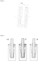
Figure 1 , which is also a figure for annotation, shows the tilting sliding system with reference marks. -
Figure 2 shows an adjustable system (according toDE202017105703U1 ) currently used as a current state of the art. -
Figure 3 shows an adjustable system (according toAU 2020100403 A4 -
Figure 4 shows a tilting sliding system, geometry and the tilt range of the glass panel. -
Figure 5 shows a tilting sliding system also with reference marks; the principle of tilting the glass panel; possible movements of individual parts. -
Figure 6 shows a tilting sliding system also with reference marks; the orientation of the parts of the tilting sliding system for extending the tilting range. -
Figure 7 shows a tilting sliding system also with reference marks; the functional areas of the slider. -
Figure 8 shows a tilting sliding system also with reference marks; the functional areas of the bed. -
Figure 9 shows a tilting sliding system also with reference marks; the position of the eccentric clamp. - It is to be understood that the various embodiments of the invention are presented by way of illustration and not by way of limitation. Those skilled in the art will find, or will be able to ascertain using no more than routine experimentation, many equivalents to specific embodiments of the invention. Such equivalents will also fall within the scope of the following patent claims. It is not a problem for those skilled in the art to optimally design the structure and its elements. Such optimized solutions will also fall within the scope of the following patent claims.
- Example of an embodiment of the invention - the tilting sliding system 1 - designed for clamping and adjusting the inclination of a
glass panel 80 or other railing panel filling (Figure 1 ). The assembly of the glass railing consists in attaching the supportingU-profile 10 to the building structure, then inserting the required number (depending on the length of the U-profile) ofsliders 20 withbeds 30 into the cavity of theU-profile 10, inserting asupport seal 40 into the groove on the outer (OUT) side of the U-profile 10 (from the service point of view - behind the glass panel), inserting theglass panel 80 into thebed cavity 31, and inserting theeccentric clamps 50 in themounting position 51 into theclamp seat 11. The shapes of theslider 20, thebed 30 and the U-profile 10 allows sliding theslider 20 along theU-profile 10 and pivoting thebed 30 along thecylindrical surface 33. By turning the service key 60 (Figure 5 ), theslider 20 moves through thetoothing 34; thebed 30 on thecylindrical surface 33 rotates through thehelical surfaces 32 on the slider and the bed around the axis of the bearing surface of the seal 41 (Figures 7 and8 ). Simple turning of theservice key 60 by the setting angle α sets the desired tilting of theglass panel 80 in the vertical plane by the tilt angle β. The tilting sliding system 1 (Figure 6 ) is used in the range of the tilt angle β

glass panel 80 is secured witheccentric clamps 50. Due to the greater manufacturing tolerance of theglass panel thickness 80, there are twoclamp positions Figure 9 ). -
- 1
- Tilting sliding system
- 10
- U-profile
- 11
- Clamp seat
- 20
- Slider
- 21
- Bearing surface of the slider
- 22
- Helical surface of the slider
- 23
- Slider seat
- 24
- Slider cavity
- 30
- Bed
- 31
- Bed cavity
- 32
- Helical surface of the bed
- 33
- Cylindrical surface of the bed
- 34
- Bed toothing
- 40
- Support seal
- 41
- Bearing surface of the seal
- 50
- Eccentric clamp
- 51
- Mounting position
- 52
- 1st clamp position
- 53
- 2nd clamp position
- 60
- Service key
- 70
- Clamp wrench
- 80
- Glass panel
- α
- Setting angle
- β
- Tilt angle
- The tilting sliding system finds application mainly in the construction industry, in the installation of railings made of glass or other panel panels, and also in the installation of decorative or advertising panels.
Claims (5)
- The tilting sliding system (1) consists of a supporting U-profile (10), a slider (20) and a bed (30) inserted into its cavity (20); a glass panel (80) inserted into the U-profile cavity (10) is supported on the outer (OUT) side by a support seal (40) and inserted by its bottom edge into the bed cavity (31), and an eccentric clamp (50) inserted on the inner (IN) side into the clamp seat (11) and supported on the inside of the glass panel (80); and characterized in that the required β tilt angle of the glass panel (80) is achieved by turning the service key (60) inserted in the slider seat (23) and the bed toothing (34) on the inner (IN) side of the supporting U-profile (10) and by sliding the slider (20) in the U-profile cavity (10) through the helical surfaces to rotate the bed (30) on the cylindrical surface of the bed (33) around the axis of the bearing surface of the seal (41).
- The tilting sliding system (1) according to Claim 1 characterized in that there is a groove in the upper part of the cavity of the supporting U-profile (10) for accommodating a support seal (40) and a clamp seat (11); that a support seal (40) is inserted in the groove on the outer (OUT) side of the supporting U-profile (10); that the bearing surfaces of the slider (21) form surfaces for the longitudinal sliding and support of the slider (20) against the walls of the cavity of the supporting U-profile (10) and are parallel with them; that the longitudinal helical surfaces of the slider (22) are on the inner sides of the slider (20) to rest on the longitudinal helical surfaces of the bed (32) on the outer walls of the bed (30); that a bed (30) is inserted in the cavity of the slider (24); that longitudinal helical surfaces of the bed (32) are on the outer walls of the bed (30) to rest on the longitudinal helical surfaces of the slider (22) on the inner walls of the slider (20); that the bed (30) is leaned with its cylindrical surface of the bed (33) on the lower surface of the supporting U-profile cavity (10); that the axis of the cylindrical surface of the bed (33) is identical to the axis of the bearing surface of the seal (41).
- The tilting sliding system (1) according to Claims 1 and 2 characterized in that the service key (60) is inserted on the inner (IN) side of the supporting U-profile (10) into the slider seat (23) and the bed toothing (34); that by turning the service key (60) by the setting angle α the slider (20) is moved longitudinally on the bearing surfaces of the slider (21) in the cavity of the supporting U-profile (10), and the bed (30) is rotated through the longitudinal helical surfaces of the slider (22) and the helical surfaces of the bed (32) by the tilt angle β on the cylindrical surface of the bed (33) and the lower surface of the cavity of the supporting U-profile (10) around the axis of the bearing surface of the seal (41).
- The tilting sliding system (1) according to Claims 1 to 3 characterized in that the range of the tilt angle β = -0.5° + 1.1° and, after rotating the slider around the vertical axis by 180°, the range of the tilt angle is β = -1.1° + 0.5°.
- The tilting sliding system (1) according to Claims 1 to 4 characterized in that an eccentric clamp (50) is inserted into inner (IN) side of the U-profile (10) to the seat of the clamp (11); that, after adjusting the tilt by the tilt angle β, the position of the glass panel (80) in the U-profile cavity (10) is secured by turning the eccentric clamp (50) with the clamp wrench (70); and that due to the greater manufacturing tolerance of the glass panel thickness (80), there are two clamp positions (52), (53) to fix the glass panel (80) in.
Applications Claiming Priority (1)
| Application Number | Priority Date | Filing Date | Title |
|---|---|---|---|
| SK44-2022A SK442022A3 (en) | 2022-05-02 | 2022-05-02 | Tilting sliding system |
Publications (2)
| Publication Number | Publication Date |
|---|---|
| EP4273346A1 true EP4273346A1 (en) | 2023-11-08 |
| EP4273346B1 EP4273346B1 (en) | 2026-02-11 |
Family
ID=82058229
Family Applications (1)
| Application Number | Title | Priority Date | Filing Date |
|---|---|---|---|
| EP22020245.1A Active EP4273346B1 (en) | 2022-05-02 | 2022-05-30 | Tilting sliding system |
Country Status (2)
| Country | Link |
|---|---|
| EP (1) | EP4273346B1 (en) |
| SK (1) | SK442022A3 (en) |
Citations (4)
| Publication number | Priority date | Publication date | Assignee | Title |
|---|---|---|---|---|
| DE202017105703U1 (en) | 2017-09-20 | 2018-01-24 | Q-Railing Europe Gmbh & Co. Kg | System for aligning railing panels |
| WO2018047179A1 (en) * | 2016-09-11 | 2018-03-15 | Tomak Ltd. | System and method for plate alignment |
| AU2020100403A4 (en) | 2019-07-05 | 2020-04-23 | Qingdao Raising Inox CO., LTD | Adjustable glass railing assembly |
| EP3816362A1 (en) * | 2019-10-29 | 2021-05-05 | Logli Massimo S.P.A. | Support for panel with side blocking device |
-
2022
- 2022-05-02 SK SK44-2022A patent/SK442022A3/en unknown
- 2022-05-30 EP EP22020245.1A patent/EP4273346B1/en active Active
Patent Citations (4)
| Publication number | Priority date | Publication date | Assignee | Title |
|---|---|---|---|---|
| WO2018047179A1 (en) * | 2016-09-11 | 2018-03-15 | Tomak Ltd. | System and method for plate alignment |
| DE202017105703U1 (en) | 2017-09-20 | 2018-01-24 | Q-Railing Europe Gmbh & Co. Kg | System for aligning railing panels |
| AU2020100403A4 (en) | 2019-07-05 | 2020-04-23 | Qingdao Raising Inox CO., LTD | Adjustable glass railing assembly |
| EP3816362A1 (en) * | 2019-10-29 | 2021-05-05 | Logli Massimo S.P.A. | Support for panel with side blocking device |
Also Published As
| Publication number | Publication date |
|---|---|
| SK442022A3 (en) | 2024-05-22 |
| EP4273346B1 (en) | 2026-02-11 |
Similar Documents
| Publication | Publication Date | Title |
|---|---|---|
| US10218305B1 (en) | End clamp for attaching solar panels to roofs | |
| CN1291112C (en) | Support for shower head | |
| KR101956946B1 (en) | Kinematic fixture for transparent part | |
| US10508441B2 (en) | Demountable wall system | |
| EP1114899A2 (en) | Components for roof assemblies | |
| EP4273346A1 (en) | Tilting sliding system | |
| EP3816362B1 (en) | Support for panel with side blocking device | |
| WO2008138130A1 (en) | Articulating post for a topless and bottomless glass post system | |
| ES2931825T3 (en) | Fixing arrangement with tolerance compensation for fixing a component to a structure | |
| US6041563A (en) | Fixing device for fixing panels to a building, and building provided with panels fixed with said fixing device | |
| EP2677109A1 (en) | Fastener for a sunshade | |
| CN105604425A (en) | Roller carriage for the reception of a sliding door with a height adjusting device | |
| EP1970515A2 (en) | Sliding and locking device | |
| EP4159950A1 (en) | Tilting clamping system for railing panels | |
| CA3055499C (en) | Horizontal panel alignment system | |
| EP2703578A2 (en) | Construction Panel | |
| CN100338328C (en) | A hinging device for a glazing system | |
| EP4350156A1 (en) | Holding, clamping and adjustment fitting of glass panel vertical inclination within holding section | |
| JPH07105708A (en) | Solar reflector | |
| EP2644812A2 (en) | Glazing system or such like | |
| WO2001057336A1 (en) | Improvements in or relating to conservatories | |
| EP4341508B1 (en) | Support equipment for panels | |
| CN217397515U (en) | Electronic glass kiln moving device | |
| DE29700222U1 (en) | Leveling device | |
| US20240295142A1 (en) | Trim retainer systems and methods |
Legal Events
| Date | Code | Title | Description |
|---|---|---|---|
| STAA | Information on the status of an ep patent application or granted ep patent |
Free format text: STATUS: UNKNOWN |
|
| PUAI | Public reference made under article 153(3) epc to a published international application that has entered the european phase |
Free format text: ORIGINAL CODE: 0009012 |
|
| STAA | Information on the status of an ep patent application or granted ep patent |
Free format text: STATUS: THE APPLICATION HAS BEEN PUBLISHED |
|
| AK | Designated contracting states |
Kind code of ref document: A1 Designated state(s): AL AT BE BG CH CY CZ DE DK EE ES FI FR GB GR HR HU IE IS IT LI LT LU LV MC MK MT NL NO PL PT RO RS SE SI SK SM TR |
|
| STAA | Information on the status of an ep patent application or granted ep patent |
Free format text: STATUS: REQUEST FOR EXAMINATION WAS MADE |
|
| 17P | Request for examination filed |
Effective date: 20240430 |
|
| RBV | Designated contracting states (corrected) |
Designated state(s): AL AT BE BG CH CY CZ DE DK EE ES FI FR GB GR HR HU IE IS IT LI LT LU LV MC MK MT NL NO PL PT RO RS SE SI SK SM TR |
|
| GRAP | Despatch of communication of intention to grant a patent |
Free format text: ORIGINAL CODE: EPIDOSNIGR1 |
|
| STAA | Information on the status of an ep patent application or granted ep patent |
Free format text: STATUS: GRANT OF PATENT IS INTENDED |
|
| RIC1 | Information provided on ipc code assigned before grant |
Ipc: E04F 11/18 20060101AFI20250804BHEP |
|
| GRAS | Grant fee paid |
Free format text: ORIGINAL CODE: EPIDOSNIGR3 |
|
| INTG | Intention to grant announced |
Effective date: 20250822 |
|
| GRAA | (expected) grant |
Free format text: ORIGINAL CODE: 0009210 |
|
| STAA | Information on the status of an ep patent application or granted ep patent |
Free format text: STATUS: THE PATENT HAS BEEN GRANTED |
|
| AK | Designated contracting states |
Kind code of ref document: B1 Designated state(s): AL AT BE BG CH CY CZ DE DK EE ES FI FR GB GR HR HU IE IS IT LI LT LU LV MC MK MT NL NO PL PT RO RS SE SI SK SM TR |
|
| REG | Reference to a national code |
Ref country code: CH Ref legal event code: F10 Free format text: ST27 STATUS EVENT CODE: U-0-0-F10-F00 (AS PROVIDED BY THE NATIONAL OFFICE) Effective date: 20260211 Ref country code: GB Ref legal event code: FG4D |
|
| REG | Reference to a national code |
Ref country code: DE Ref legal event code: R096 Ref document number: 602022030008 Country of ref document: DE |
|
| REG | Reference to a national code |
Ref country code: IE Ref legal event code: FG4D |