EP4273260A1 - Sampling method - Google Patents
Sampling method Download PDFInfo
- Publication number
- EP4273260A1 EP4273260A1 EP22749600.7A EP22749600A EP4273260A1 EP 4273260 A1 EP4273260 A1 EP 4273260A1 EP 22749600 A EP22749600 A EP 22749600A EP 4273260 A1 EP4273260 A1 EP 4273260A1
- Authority
- EP
- European Patent Office
- Prior art keywords
- sample
- sampling
- flow path
- sensor
- introduction
- Prior art date
- Legal status (The legal status is an assumption and is not a legal conclusion. Google has not performed a legal analysis and makes no representation as to the accuracy of the status listed.)
- Pending
Links
Images






Classifications
-
- C—CHEMISTRY; METALLURGY
- C12—BIOCHEMISTRY; BEER; SPIRITS; WINE; VINEGAR; MICROBIOLOGY; ENZYMOLOGY; MUTATION OR GENETIC ENGINEERING
- C12M—APPARATUS FOR ENZYMOLOGY OR MICROBIOLOGY; APPARATUS FOR CULTURING MICROORGANISMS FOR PRODUCING BIOMASS, FOR GROWING CELLS OR FOR OBTAINING FERMENTATION OR METABOLIC PRODUCTS, i.e. BIOREACTORS OR FERMENTERS
- C12M41/00—Means for regulation, monitoring, measurement or control, e.g. flow regulation
- C12M41/30—Means for regulation, monitoring, measurement or control, e.g. flow regulation of concentration
- C12M41/34—Means for regulation, monitoring, measurement or control, e.g. flow regulation of concentration of gas
-
- G—PHYSICS
- G01—MEASURING; TESTING
- G01N—INVESTIGATING OR ANALYSING MATERIALS BY DETERMINING THEIR CHEMICAL OR PHYSICAL PROPERTIES
- G01N1/00—Sampling; Preparing specimens for investigation
- G01N1/02—Devices for withdrawing samples
- G01N1/10—Devices for withdrawing samples in the liquid or fluent state
- G01N1/20—Devices for withdrawing samples in the liquid or fluent state for flowing or falling materials
- G01N1/2035—Devices for withdrawing samples in the liquid or fluent state for flowing or falling materials by deviating part of a fluid stream, e.g. by drawing-off or tapping
-
- C—CHEMISTRY; METALLURGY
- C12—BIOCHEMISTRY; BEER; SPIRITS; WINE; VINEGAR; MICROBIOLOGY; ENZYMOLOGY; MUTATION OR GENETIC ENGINEERING
- C12M—APPARATUS FOR ENZYMOLOGY OR MICROBIOLOGY; APPARATUS FOR CULTURING MICROORGANISMS FOR PRODUCING BIOMASS, FOR GROWING CELLS OR FOR OBTAINING FERMENTATION OR METABOLIC PRODUCTS, i.e. BIOREACTORS OR FERMENTERS
- C12M29/00—Means for introduction, extraction or recirculation of materials, e.g. pumps
-
- C—CHEMISTRY; METALLURGY
- C12—BIOCHEMISTRY; BEER; SPIRITS; WINE; VINEGAR; MICROBIOLOGY; ENZYMOLOGY; MUTATION OR GENETIC ENGINEERING
- C12M—APPARATUS FOR ENZYMOLOGY OR MICROBIOLOGY; APPARATUS FOR CULTURING MICROORGANISMS FOR PRODUCING BIOMASS, FOR GROWING CELLS OR FOR OBTAINING FERMENTATION OR METABOLIC PRODUCTS, i.e. BIOREACTORS OR FERMENTERS
- C12M33/00—Means for introduction, transport, positioning, extraction, harvesting, peeling or sampling of biological material in or from the apparatus
-
- C—CHEMISTRY; METALLURGY
- C12—BIOCHEMISTRY; BEER; SPIRITS; WINE; VINEGAR; MICROBIOLOGY; ENZYMOLOGY; MUTATION OR GENETIC ENGINEERING
- C12M—APPARATUS FOR ENZYMOLOGY OR MICROBIOLOGY; APPARATUS FOR CULTURING MICROORGANISMS FOR PRODUCING BIOMASS, FOR GROWING CELLS OR FOR OBTAINING FERMENTATION OR METABOLIC PRODUCTS, i.e. BIOREACTORS OR FERMENTERS
- C12M41/00—Means for regulation, monitoring, measurement or control, e.g. flow regulation
- C12M41/48—Automatic or computerized control
-
- C—CHEMISTRY; METALLURGY
- C12—BIOCHEMISTRY; BEER; SPIRITS; WINE; VINEGAR; MICROBIOLOGY; ENZYMOLOGY; MUTATION OR GENETIC ENGINEERING
- C12N—MICROORGANISMS OR ENZYMES; COMPOSITIONS THEREOF; PROPAGATING, PRESERVING, OR MAINTAINING MICROORGANISMS; MUTATION OR GENETIC ENGINEERING; CULTURE MEDIA
- C12N1/00—Microorganisms; Compositions thereof; Processes of propagating, maintaining or preserving microorganisms or compositions thereof; Processes of preparing or isolating a composition containing a microorganism; Culture media therefor
-
- C—CHEMISTRY; METALLURGY
- C12—BIOCHEMISTRY; BEER; SPIRITS; WINE; VINEGAR; MICROBIOLOGY; ENZYMOLOGY; MUTATION OR GENETIC ENGINEERING
- C12N—MICROORGANISMS OR ENZYMES; COMPOSITIONS THEREOF; PROPAGATING, PRESERVING, OR MAINTAINING MICROORGANISMS; MUTATION OR GENETIC ENGINEERING; CULTURE MEDIA
- C12N5/00—Undifferentiated human, animal or plant cells, e.g. cell lines; Tissues; Cultivation or maintenance thereof; Culture media therefor
-
- C—CHEMISTRY; METALLURGY
- C12—BIOCHEMISTRY; BEER; SPIRITS; WINE; VINEGAR; MICROBIOLOGY; ENZYMOLOGY; MUTATION OR GENETIC ENGINEERING
- C12Q—MEASURING OR TESTING PROCESSES INVOLVING ENZYMES, NUCLEIC ACIDS OR MICROORGANISMS; COMPOSITIONS OR TEST PAPERS THEREFOR; PROCESSES OF PREPARING SUCH COMPOSITIONS; CONDITION-RESPONSIVE CONTROL IN MICROBIOLOGICAL OR ENZYMOLOGICAL PROCESSES
- C12Q1/00—Measuring or testing processes involving enzymes, nucleic acids or microorganisms; Compositions therefor; Processes of preparing such compositions
- C12Q1/02—Measuring or testing processes involving enzymes, nucleic acids or microorganisms; Compositions therefor; Processes of preparing such compositions involving viable microorganisms
- C12Q1/24—Methods of sampling, or inoculating or spreading a sample; Methods of physically isolating an intact microorganisms
-
- C—CHEMISTRY; METALLURGY
- C12—BIOCHEMISTRY; BEER; SPIRITS; WINE; VINEGAR; MICROBIOLOGY; ENZYMOLOGY; MUTATION OR GENETIC ENGINEERING
- C12M—APPARATUS FOR ENZYMOLOGY OR MICROBIOLOGY; APPARATUS FOR CULTURING MICROORGANISMS FOR PRODUCING BIOMASS, FOR GROWING CELLS OR FOR OBTAINING FERMENTATION OR METABOLIC PRODUCTS, i.e. BIOREACTORS OR FERMENTERS
- C12M41/00—Means for regulation, monitoring, measurement or control, e.g. flow regulation
- C12M41/30—Means for regulation, monitoring, measurement or control, e.g. flow regulation of concentration
- C12M41/32—Means for regulation, monitoring, measurement or control, e.g. flow regulation of concentration of substances in solution
Definitions
- the present invention relates to a sampling method.
- US9,442,047B discloses a sampling method using a sampling system provided with a sampling flow path for collecting a sample of a liquid from a cell culturing device.
- the sampling system may include a biosensor provided in the sampling flow path to be in contact with the sample, and an introduction path for introducing a cleaning solution to a more upstream side than the biosensor in the sampling flow path.
- a sampling step of causing the sample to flow through the sampling flow path and bringing the sample into contact with the biosensor, and a cleaning step of introducing the cleaning solution from the introduction path into the sampling flow path and removing the sample adhering to the biosensor to prevent deterioration of a catalyst in the biosensor are performed.
- the cleaning solution remains in the introduction path and a more downstream side than a connection portion in the sampling flow path. Thereafter, when the sampling step is performed, the sample washes away the cleaning solution remaining in the sampling flow path. However, the cleaning solution in the introduction path remains. Accordingly, in the sampling step, the cleaning solution in the introduction path may be mixed into the sample in the connection portion.
- the invention has been made in view of such a problem, and an object thereof is to provide a sampling method capable of efficiently removing a sample adhering to a biosensor and preventing a cleaning solution from being mixed into the sample flowing through a sampling flow path.
- An aspect of the invention is a sampling method using a sampling system provided with a sampling flow path for collecting a sample of a liquid in a cell culturing device.
- the sampling system includes a biosensor provided in the sampling flow path to be in contact with the sample, and an introduction path configured to introduce a cleaning solution to a more upstream side than the biosensor in the sampling flow path.
- the sampling method includes: a sampling step of causing the sample to flow through the sampling flow path from the cell culturing device and measuring a concentration of a predetermined component in the sample by the biosensor; and a cleaning step of causing the cleaning solution to flow from the introduction path into the biosensor through the sampling flow path after the sampling step.
- the sampling step is performed twice or more, and the sampling step at second and subsequent times is performed after the cleaning step.
- the sampling step includes a sample introduction step of introducing the sample from the cell culturing device to a more downstream side than a connection portion in the introduction path in the sampling flow path, a returning step of causing the sample in the sampling flow path to flow into the introduction path from the connection portion after the sample introduction step, and a flowing step of causing the sample to flow through the sampling flow path from the cell culturing device and bringing the sample into contact with the biosensor after the returning step.
- the sample adhering to the biosensor in the sampling step can be removed by the cleaning solution in the cleaning step.
- the sample introduction step the sample is introduced from the cell culturing device to the more downstream side than the connection portion in the sampling flow path, and then the sample is caused to flow into the introduction path in the returning step. Accordingly, a vicinity of the connection portion in the sampling flow path in the introduction path can be filled with the sample (the cleaning solution can be removed from the vicinity of the connection portion in the introduction path).
- the cleaning solution in the introduction path can be prevented from being mixed from the connection portion into the sample flowing through the sampling flow path.
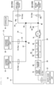
- a sampling system 10 collects samples of liquids in a plurality of cell culturing devices 200 and measures a concentration of each predetermined component in the samples.
- the sampling system 10 includes a sampling kit 12, a circuit control device 14 on which the sampling kit 12 is detachably provided, and a controller 16.
- the sampling kit 12 is a disposable product
- the circuit control device 14 is a reusable product.
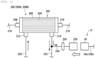
- the cell culturing device 200 includes a bioreactor 202 for culturing cells.
- the cells to be cultured are separated from a biological tissue, and for example, cells contained in blood (T cells and the like) and stem cells (ES cells, iPS cells, mesenchymal stem cells, and the like) are used.
- the bioreactor 202 is a so-called hollow fiber type bioreactor.
- the bioreactor 202 includes a large number of (a plurality of) hollow fibers 204 and a cylindrical housing 206 that accommodates the hollow fibers 204.
- a plurality of pores are formed in a wall portion constituting each hollow fiber 204.
- the pores allow communication between an intra capillary (IC) region, which is an inner cavity of the hollow fiber 204, and an extra capillary (EC) region located outside the hollow fiber 204 in the housing 206.
- IC intra capillary
- EC extra capillary
- a diameter of each pore is set to such a size that allows small molecules (for example, water, ions, oxygen, or lactic acid) to pass therethrough and prevents passage of macromolecules (cells, etc.) therethrough.
- the housing 206 is provided with an IC inlet port 208, an IC outlet port 210, an EC inlet port 212, and an EC outlet port 214.
- the IC inlet port 208 is provided at one end of the housing 206.
- the IC inlet port 208 introduces, into the IC region of the bioreactor 202, a liquid (a solution containing cells, a culture medium, or the like) guided from an IC inlet flow path 216.
- the IC outlet port 210 is provided at the other end of the housing 206.
- the IC outlet port 210 causes the liquid having flowed through the IC region of the bioreactor 202 to be introduced to an IC outlet flow path 218.
- the EC inlet port 212 and the EC outlet port 214 are provided on an outer peripheral surface of the housing 206.
- the EC inlet port 212 introduces a culture medium introduced from an EC inlet flow path 220 into the EC region of the bioreactor 202.
- the EC outlet port 214 introduces the culture medium having flowed through the EC region of the bioreactor 202 to an EC outlet flow path 222.
- a suitable culture medium may be selected according to biological cells, and for example, a culture medium prepared by adding various amino acids, vitamins, serum, and the like to a balanced salt solution (BSS) as a basic solution is used.
- BSS balanced salt solution
- the EC outlet flow path 222 is connected to a connection line 224 for guiding the culture medium having flowed through the EC region to the sampling kit 12.
- the connection line 224 is provided with a sterile filter 226 and a sampling connector 228.
- the sterile filter 226 sterilely holds a portion of the cell culturing device 200 closer to the EC outlet flow path 222 than the sterile filter 226.
- An introduction connector 42 of the sampling kit 12 is detachably connected to the sampling connector 228.
- the sampling system 10 collects, as the sample, the culture medium having flowed through the EC region of the cell culturing device 200.
- the sample to be collected by the sampling system 10 is not limited to the culture medium having flowed through the EC region, and may be a culture medium, another liquid, or the like having flowed through the IC region.
- the sampling kit 12 includes a cleaning solution accommodation unit 18, a standard solution accommodation unit 20, a waste liquid accommodation unit 22, a connection circuit 24, a first sensor 26, and a second sensor 28.
- the cleaning solution accommodation unit 18, the standard solution accommodation unit 20, and the waste liquid accommodation unit 22 are formed in a bag-like shape by using a soft resin material having flexibility, such as polyvinyl chloride or a polyolefin.
- a soft resin material having flexibility such as polyvinyl chloride or a polyolefin.
- the cleaning solution accommodation unit 18, the standard solution accommodation unit 20, and the waste liquid accommodation unit 22 can be appropriately changed as long as the liquid can be accommodated.
- a cleaning solution is accommodated in the cleaning solution accommodation unit 18.
- a buffer solution or a physiological saline solution is used.
- the buffer solution include phosphate buffered saline (PBS) and tris-buffered saline (TBS).
- PBS phosphate buffered saline
- TBS tris-buffered saline
- the cleaning solution is not limited to those described above.
- the standard solution is a liquid for calibrating the first sensor 26 and the second sensor 28.
- the standard solution is a liquid in which a PH value, an O 2 value (oxygen concentration), a CO 2 value (carbon dioxide concentration), a glucose value (glucose concentration), or a lactic acid value (lactic acid concentration) is set to a specified value.
- the waste liquid accommodation unit 22 is for accommodating a waste liquid (the sample, the cleaning solution, and the standard solution) having flowed through the connection circuit 24.
- the waste liquid accommodation unit 22 is an empty bag in which no liquid is accommodated in a state before the sampling kit 12 is used.
- the connection circuit 24 includes a sampling flow path 30 for collecting the sample in the cell culturing device 200, an introduction path 32 for guiding the cleaning solution to the sampling flow path 30, and a standard solution introduction path 33 for guiding the standard solution to the introduction path 32.
- the sampling flow path 30 includes a first sample introduction path 34a, a second sample introduction path 34b, and a sample flow path 36.
- the first sample introduction path 34a guides a sample (culture medium) in the first cell culturing device 200A to the sample flow path 36.
- One end of the first sample introduction path 34a is provided with the introduction connector 42 to be mounted on the sampling connector 228 of the first cell culturing device 200A (see FIG. 2 ).
- the other end of the first sample introduction path 34a is connected to one end of the sample flow path 36.
- a connection portion between the first sample introduction path 34a and the sample flow path 36 is referred to as a first connection portion 38.
- the second sample introduction path 34b guides a sample (culture medium) in the second cell culturing device 200B to the sample flow path 36.
- One end of the second sample introduction path 34b is provided with the introduction connector 42 to be mounted on the sampling connector 228 of the second cell culturing device 200B (see FIG. 2 ).
- the other end of the second sample introduction path 34b is connected to an intermediate portion of the sample flow path 36.
- a connection portion between the second sample introduction path 34b and the sample flow path 36 is referred to as a second connection portion 40.
- the sample flow path 36 includes an intermediate flow path 44 that connects the first connection portion 38 and the second connection portion 40 to each other, and a sensor flow path 46 that connects the second connection portion 40 and the waste liquid accommodation unit 22 to each other.
- One end of the introduction path 32 is connected to the cleaning solution accommodation unit 18.
- the other end of the introduction path 32 is connected to the first connection portion 38.
- One end of the standard solution introduction path 33 is connected to the standard solution accommodation unit 20.
- the other end of the standard solution introduction path 33 is connected to an intermediate portion of the introduction path 32.
- a connection portion between the introduction path 32 and the standard solution introduction path 33 is referred to as a third connection portion 48.
- the first sensor 26 and the second sensor 28 are provided in the sensor flow path 46 to be in contact with the sample.
- the first sensor 26 is an integrally molded product, and includes a PH sensor 60 and a gas concentration sensor 62.
- the PH sensor 60 measures a PH in the sample.
- the gas concentration sensor 62 measures a gas concentration in the sample.
- the gas concentration sensor 62 includes an O 2 sensor 64 that measures an O 2 concentration in the sample and a CO 2 sensor 66 that measures a CO 2 concentration in the sample.
- the second sensor 28 is, for example, a biosensor such as an enzyme sensor.
- the second sensor 28 is provided on a more downstream side than the first sensor 26 in the sensor flow path 46.
- the second sensor 28 is an integrally molded product, and includes a glucose sensor 68 that measures a glucose concentration in the sample and a lactic acid sensor 70 that measures a lactic acid concentration in the sample.
- the second sensor 28 is not limited to the enzyme sensor, and may include a non-enzyme glucose sensor.
- a measurement item of the second sensor 28 is not limited to the glucose and the lactic acid, and may include glutamic acid or the like.
- the circuit control device 14 includes a plurality of clamps 72 and a pump 74.
- the circuit control device 14 includes, as the plurality of clamps 72, a first clamp 72a (first on-off unit), a second clamp 72b, a third clamp 72c, a fourth clamp 72d (second on-off unit), and a fifth clamp 72e.
- the first clamp 72a is disposed to face the first sample introduction path 34a in a state in which the sampling kit 12 is mounted on the circuit control device 14 (hereinafter referred to as a "set state"), and turns on or off an internal flow path in the first sample introduction path 34a.
- the second clamp 72b is disposed to face the second sample introduction path 34b in the set state, and turns on or off an internal flow path in the second sample introduction path 34b.
- the third clamp 72c is disposed to face a portion between the second sensor 28 in the sensor flow path 46 and the waste liquid accommodation unit 22 in the set state, and turns on or off an internal flow path in the portion in the sensor flow path 46.
- the fourth clamp 72d is disposed to face a portion of the introduction path 32 on a more upstream side than the third connection portion 48 in the set state, and turns on or off an internal flow path in the portion of the introduction path 32.
- the fifth clamp 72e is disposed to face the standard solution introduction path 33 in the set state, and turns on or off an internal flow path in the standard solution introduction path 33.
- the pump 74 applies a flow force to an internal liquid by rotating in a manner of squeezing a wall portion constituting a flow path (tube) of the connection circuit 24.
- the pump 74 is disposed to be in contact with a portion between the second connection portion 40 and the first sensor 26 in the sensor flow path 46 in the set state.
- the pump 74 performs a first rotation operation (rotation operation in a direction of an arrow R1) such that the flow force in a direction toward the first sensor 26 (waste liquid accommodation unit 22) is applied to a liquid flowing through the sensor flow path 46.
- the pump 74 performs a second rotation operation (rotation operation in a direction of an arrow R2) such that the flow force in a direction toward the second connection portion 40 is applied to the liquid flowing through the sensor flow path 46.
- the controller 16 (control unit) is a computer including a processor, a memory, and an input and output interface (not shown).
- the controller 16 performs overall control for the entire system by causing the processor to execute a program stored in the memory.
- the controller 16 is connected to the circuit control device 14 by communication means such as wire, radio, a network or a combination thereof. Specifically, the controller 16 controls operations of the plurality of clamps 72 and the pump 74.
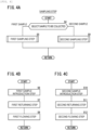
- the sampling method includes a preparation step, a priming step, a sampling step, a cleaning step, and a calibration step.
- the sampling kit 12 is mounted (set) to the circuit control device 14, the introduction connector 42 in the first sample introduction path 34a is connected to the sampling connector 228 of the first cell culturing device 200A, and the introduction connector 42 in the second sample introduction path 34b is connected to the sampling connector 228 of the second cell culturing device 200B.
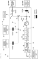
- the controller 16 causes the pump 74 to perform the first rotation operation in a state in which the third clamp 72c and the fourth clamp 72d are turned on, and the first clamp 72a, the second clamp 72b, and the fifth clamp 72e are turned off. Accordingly, the cleaning solution in the cleaning solution accommodation unit 18 is guided from the introduction path 32 to the waste liquid accommodation unit 22 through the first connection portion 38, the intermediate flow path 44, the second connection portion 40, and the sensor flow path 46 by an action of the pump 74.
- the sampling step (step S3 in FIG. 3 ) is performed.
- the controller 16 selects a sample to be collected (step S4 in FIG. 4A ). That is, the controller 16 selects which of the sample (first sample) in the first cell culturing device 200A and the sample (second sample) in the second cell culturing device 200B is to be collected based on a cell culturing state in the cell culturing device 200.
- the first sampling step is performed (step S5 in FIG. 4A ).
- the first sampling step includes a first sample introduction step, a first returning step, and a first flowing step.
- the controller 16 causes the pump 74 to perform the first rotation operation in a state in which the first clamp 72a and the third clamp 72c are turned on, and the second clamp 72b, the fourth clamp 72d, and the fifth clamp 72e are turned off. Accordingly, the first sample in the first cell culturing device 200A is guided from the first sample introduction path 34a to the intermediate flow path 44 (sample flow path 36) through the first connection portion 38 by the action of the pump 74.
- the controller 16 stops the first rotation operation, for example, when the first sample reaches a position in front of the first sensor 26 in the sensor flow path 46 (for example, reaches a position closer to the first sensor 26 than a center of a section between the second connection portion 40 and the first sensor 26 in the sensor flow path 46).
- the controller 16 stops the first rotation operation of the pump 74 when a first time has elapsed since the pump 74 is caused to perform the first rotation operation.
- the first time is an elapsed time from a time when the pump 74 is caused to perform the first rotation operation until a time when the first sample reaches the position in front of the first sensor 26 in the sensor flow path 46.
- a sample detection sensor 80 see FIG.
- the controller 16 may stop the first rotation operation of the pump 74 when the sample detection sensor 80 has detected the sample.
- a timing at which the first rotation operation of the pump 74 is stopped can be appropriately changed. That is, the timing at which the first rotation operation of the pump 74 is stopped may be a timing at which the first sample has reached the intermediate flow path 44, a timing at which the first sample has reached a section between the first sensor 26 and the second sensor 28 in the sensor flow path 46, a timing at which the first sample has reached a section between the second sensor 28 in the sensor flow path 46 and the waste liquid accommodation unit 22, or a timing after the first sample is accommodated in the waste liquid accommodation unit 22.
- the controller 16 causes the pump 74 to perform the second rotation operation in a state in which the third clamp 72c and the fourth clamp 72d are turned on and the first clamp 72a, the second clamp 72b, and the fifth clamp 72e are turned off. Accordingly, the first sample in the sample flow path 36 flows into the introduction path 32 by the action of the pump 74, and the cleaning solution in the introduction path 32 is pushed back into the cleaning solution accommodation unit 18. Accordingly, the cleaning solution remaining in a vicinity of the first connection portion 38 in the introduction path 32 is removed (replaced with the first sample).
- the controller 16 stops the second rotation operation of the pump 74, for example, before the first sample reaches the third connection portion 48 in the introduction path 32.
- the controller 16 stops the second rotation operation of the pump 74 when a second time has elapsed since the pump 74 is caused to perform the second rotation operation.
- the second time is an elapsed time from a time when the pump 74 is caused to perform the second rotation operation until a time when the vicinity of the first connection portion 38 in the introduction path 32 is replaced with the sample.
- a sample detection sensor 82 see FIG.
- the controller 16 may stop the second rotation operation of the pump 74 when the sample detection sensor 82 has detected the sample.
- a timing at which the second rotation operation of the pump 74 is stopped can be appropriately changed. That is, the timing at which the second rotation operation of the pump 74 is stopped may be a timing at which the first sample has reached a section between the third connection portion 48 in the introduction path 32 and the cleaning solution accommodation unit 18.
- the controller 16 causes the pump 74 to perform the first rotation operation in a state in which the first clamp 72a and the third clamp 72c are turned on, and the second clamp 72b, the fourth clamp 72d, and the fifth clamp 72e are turned off. Accordingly, the first sample in the first cell culturing device 200A is guided to the waste liquid accommodation unit 22 through the first sample introduction path 34a, the first connection portion 38, the intermediate flow path 44, the second connection portion 40, and the sensor flow path 46 by the action of the pump 74.
- the cleaning solution is prevented from being mixed from the first connection portion 38 into the first sample flowing through the sampling flow path 30. That is, a change in the concentration of the first sample due to mixing of the cleaning solution is prevented.
- the first sensor 26 and the second sensor 28 are in contact with the first sample.
- a PH, an O 2 concentration, and a CO 2 concentration in the first sample are measured.
- a measurement result obtained by the first sensor 26 is transmitted to the controller 16.
- a glucose concentration and a lactic acid concentration in the first sample are measured.
- a measurement result obtained by the second sensor 28 is transmitted to the controller 16.
- the controller 16 controls a culture condition in the first cell culturing device 200A based on the measurement results obtained by the first sensor 26 and the second sensor 28.
- a second sampling step is performed (step S9 in FIG. 4A ).
- the second sampling step includes a second sample introduction step, a second returning step, and a second flowing step.
- the controller 16 causes the pump 74 to perform the first rotation operation in a state in which the second clamp 72b and the third clamp 72c are turned on, and the first clamp 72a, the fourth clamp 72d, and the fifth clamp 72e are turned off. Accordingly, the second sample in the second cell culturing device 200B is guided from the second sample introduction path 34b to the sensor flow path 46 (sample flow path 36) through the second connection portion 40 by the action of the pump 74.
- the controller 16 stops the first rotation operation, for example, when the second sample reaches the position in front of the first sensor 26 in the sensor flow path 46 (for example, reaches a position closer to the first sensor 26 than the center of the section between the second connection portion 40 and the first sensor 26 in the sensor flow path 46).
- the controller 16 stops the first rotation operation of the pump 74 when a third time has elapsed since the pump 74 is caused to perform the first rotation operation.
- the third time is an elapsed time from a time when the pump 74 is caused to perform the first rotation operation until a time when the second sample reaches the position in front of the first sensor 26 in the sensor flow path 46.
- a sample detection sensor 84 that detects the sample flowing through the portion between the second connection portion 40 and the first sensor 26 in the sensor flow path 46 may be provided in the circuit control device 14, and the controller 16 may stop the first rotation operation of the pump 74 when the sample detection sensor 84 has detected the sample.
- a timing at which the first rotation operation of the pump 74 is stopped can be appropriately changed. That is, the timing at which the first rotation operation of the pump 74 is stopped may be a timing at which the second sample has reached a section between the first sensor 26 and the second sensor 28 in the sensor flow path 46, a timing at which the second sample has reached the section between the second sensor 28 in the sensor flow path 46 and the waste liquid accommodation unit 22, or a timing after the second sample is accommodated in the waste liquid accommodation unit 22.
- the controller 16 causes the pump 74 to perform the second rotation operation in the state in which the third clamp 72c and the fourth clamp 72d are turned on, and the first clamp 72a, the second clamp 72b, and the fifth clamp 72e are turned off. Accordingly, the second sample in the sensor flow path 46 flows into the intermediate flow path 44 by the action of the pump 74, and the cleaning solution remaining in the intermediate flow path 44 is pushed back to the introduction path 32 through the first connection portion 38. Accordingly, the cleaning solution remaining in the vicinity of the second connection portion 40 in the intermediate flow path 44 is removed (replaced with the second sample).
- the controller 16 stops the second rotation operation of the pump 74, for example, before the second sample reaches the first connection portion 38.
- the controller 16 stops the second rotation operation of the pump 74 when a fourth time has elapsed since the pump 74 is caused to perform the second rotation operation.
- the fourth time is an elapsed time from a time when the pump 74 is caused to perform the second rotation operation until a time when the vicinity of the second connection portion 40 in the intermediate flow path 44 is replaced with the second sample.
- a sample detection sensor 86 (see FIG. 10 ) that detects the sample flowing through the intermediate flow path 44 may be provided in the circuit control device 14, and the controller 16 may stop the second rotation operation of the pump 74 when the sample detection sensor 86 has detected the sample.
- a timing at which the second rotation operation of the pump 74 is stopped can be appropriately changed. That is, the timing at which the second rotation operation of the pump 74 is stopped may be a timing at which the second sample has reached the introduction path 32.
- step S12 in FIG. 4C the controller 16 causes the pump 74 to perform the first rotation operation in a state in which the second clamp 72b and the third clamp 72c are turned on, and the first clamp 72a, the fourth clamp 72d, and the fifth clamp 72e are turned off. Accordingly, the second sample in the second cell culturing device 200B is guided to the waste liquid accommodation unit 22 through the second sample introduction path 34b, the second connection portion 40, and the sensor flow path 46 by the action of the pump 74.
- the cleaning solution is prevented from being mixed from the second connection portion 40 into the second sample flowing through the sampling flow path 30. That is, a change in the concentration of the second sample due to mixing of the cleaning solution is prevented.
- a PH, an O 2 concentration, and a CO 2 concentration in the second sample are measured.
- a measurement result obtained by the first sensor 26 is transmitted to the controller 16.
- a glucose concentration and a lactic acid concentration in the second sample are measured.
- a measurement result obtained by the second sensor 28 is transmitted to the controller 16.
- the controller 16 controls a culture condition in the second cell culturing device 200B based on the measurement results obtained by the first sensor 26 and the second sensor 28.
- the controller 16 determines whether cell culturing in the first cell culturing device 200A and the second cell culturing device 200B is completed (step S13). When the controller 16 determines that the cell culturing is not completed (step S13: NO), the cleaning step (step S14) is performed. In the cleaning step, as shown in FIG. 5 , the controller 16 operates the plurality of clamps 72 and the pump 74 as in the priming step. Accordingly, the cleaning solution in the cleaning solution accommodation unit 18 flows through the first sensor 26 and the second sensor 28 and is guided to the waste liquid accommodation unit 22.
- the sample adhering to the PH sensor 60, the O 2 sensor 64, and the CO 2 sensor 66 is removed by the cleaning solution.
- the sample adhering to the glucose sensor 68 and the lactic acid sensor 70 is removed by the cleaning solution.
- step S15 the calibration step (step S15) is performed as necessary.
- the controller 16 causes the pump 74 to perform the first rotation operation in a state in which the third clamp 72c and the fifth clamp 72e are turned on, and the first clamp 72a, the second clamp 72b, and the fourth clamp 72d are turned off. Accordingly, the standard solution in the standard solution accommodation unit 20 is guided to the waste liquid accommodation unit 22 through the standard solution introduction path 33, the introduction path 32, the first connection portion 38, the intermediate flow path 44, the second connection portion 40, and the sensor flow path 46 by the action of the pump 74.
- the first sensor 26 measures a PH, an O 2 concentration, and a CO 2 concentration in the standard solution.
- a measurement result obtained by the first sensor 26 is transmitted to the controller 16.
- the controller 16 performs calibration on the PH sensor 60, the O 2 sensor 64, and the CO 2 sensor 66 based on the measurement result obtained by the first sensor 26.
- the second sensor 28 measures a glucose concentration and a lactic acid concentration in the standard solution.
- a measurement result obtained by the second sensor 28 is transmitted to the controller 16.
- the controller 16 performs calibration on the glucose sensor 68 and the lactic acid sensor 70 based on the measurement result obtained by the second sensor 28.
- the steps after step S3 are sequentially performed. In the present embodiment, the sampling step is performed twice or more.
- step S13 in FIG. 3 YES
- a flow of a series of operations is completed.
- the present embodiment has effects as follows.
- the sampling method includes the sampling step of causing the first sample to flow through the sampling flow path 30 from the first cell culturing device 200A and measuring the concentration of a predetermined component in the sample by the second sensor 28, and the cleaning step of causing the cleaning solution to flow from the introduction path 32 to the second sensor 28 through the sampling flow path 30 after the sampling step.
- a treatment including the sampling step and the cleaning step is performed a plurality of times.
- the sampling step includes the first sample introduction step of introducing the first sample from the first cell culturing device 200A to a more downstream side than the first connection portion 38, the first returning step of causing the first sample in the sampling flow path 30 to flow into the introduction path 32 from the first connection portion 38 after the first sample introduction step, and the flowing step of causing the first sample to flow through the sampling flow path 30 from the first cell culturing device 200A and bringing the first sample into contact with the second sensor 28 after the first returning step.
- the sample adhering to the second sensor 28 in the sampling step can be further removed by the cleaning solution in the cleaning step.
- the first sample introduction step the first sample is introduced from the first cell culturing device 200A to the more downstream side than the first connection portion 38 in the sampling flow path 30, and then the first sample is caused to flow into the introduction path 32 in the first returning step. Accordingly, the vicinity of the first connection portion 38 in the introduction path 32 can be filled with the first sample (the cleaning solution can be removed from the vicinity of the first connection portion 38 in the introduction path 32).
- the cleaning solution in the introduction path 32 can be prevented from being mixed from the first connection portion 38 into the first sample flowing through the sampling flow path 30.
- the cleaning solution accommodation unit 18 in which the cleaning solution is accommodated is connected to the introduction path 32.
- an inflow of the first sample into the introduction path 32 is stopped before the first sample reaches the cleaning solution accommodation unit 18.
- the sampling flow path 30 includes the sample flow path 36 provided with the second sensor 28, and the first sample introduction path 34a for guiding the first sample in the first cell culturing device 200A to the first connection portion 38.
- the sampling system 10 includes the first clamp 72a (first on-off unit) that turns on or off the first sample introduction path 34a, the fourth clamp 72d (second on-off unit) that turns on or off the introduction path 32, and the pump 74 provided in the sample flow path 36.
- the cleaning solution is caused to flow through the second sensor 28 by driving the pump 74 in a state in which the first clamp 72a is turned off and the fourth clamp 72d is turned on.
- the first sample introduction step the first sample is introduced to the sample flow path 36 by driving the pump 74 in a state in which the first clamp 72a is turned on and the fourth clamp 72d is turned off.
- the first returning step the first sample in the sample flow path 36 is caused to flow into the introduction path 32 from the first connection portion 38 by driving the pump 74 in the state in which the first clamp 72a is turned off and the fourth clamp 72d is turned on.
- the first sample is brought into contact with the second sensor 28 by driving the pump 74 in the state in which the first clamp 72a is turned on and the fourth clamp 72d is turned off.
- the cleaning step, the first sample introduction step, the first returning step, and the first flowing step can be easily performed by driving the first clamp 72a, the fourth clamp 72d, and the pump 74.
- the driving of the pump 74 is stopped based on an elapsed time (first time and second time) from a start of the driving of the pump 74.
- the sampling system 10 includes the sample detection sensor 80 for detecting the sample flowing through the sample flow path 36.
- the driving of the pump 74 is stopped when the sample detection sensor 80 has detected the first sample.
- an appropriate amount of the first sample can be introduced into the sample flow path 36 in the first sample introduction step.
- the sampling system 10 includes the sample detection sensor 82 for detecting the first sample flowing through the introduction path 32.
- the driving of the pump 74 is stopped when the sample detection sensor 82 has detected the first sample.
- the gas concentration sensor 62 which measures a gas concentration in the first sample in a manner of being in contact with the first sample is provided on the more downstream side than the first connection portion 38 in the sampling flow path 30. In the first flowing step, the first sample is caused to flow through the sampling flow path 30 and is brought into contact with the gas concentration sensor 62.
- the gas concentration in the first sample can be measured by the gas concentration sensor 62. Since the cleaning solution is prevented from being mixed into the first sample by the first sample introduction step and the first returning step, the gas concentration in the first sample can be accurately measured by the gas concentration sensor 62.
- the sampling system 10 may collect a sample in one cell culturing device 200 and measure a concentration of a predetermined component thereof.
- the sampling system may not include the second sample introduction path 34b.
- the sampling system may individually collect samples in three or more cell culturing devices 200 and measure concentrations of a predetermined component.
- the number of cell culturing devices 200 connected to the sampling flow path 30 may be three or more.
- the number of sample introduction paths corresponds to the number of cell culturing devices 200.
- the invention is not limited to the above embodiment, and various modifications can be made without departing from the gist of the invention.
- the above embodiment describes a cell culturing system in which the sampling system 10 and the cell culturing device 200 are separately formed, but the cell culturing system may be one in which the sampling system 10 and the cell culturing device 200 are integrated (unified) with each other.
- the above embodiment discloses a sampling method using a sampling system (10) provided with a sampling flow path (30) for collecting a sample of a liquid in a cell culturing device (20A).
- the sampling system includes a biosensor (28) provided in the sampling flow path to be in contact with the sample, and an introduction path (32) configured to introduce a cleaning solution to a more upstream side than the biosensor in the sampling flow path.
- the sampling method includes: a sampling step (step S3) of causing the sample to flow through the sampling flow path from the cell culturing device and measuring a concentration of a predetermined component in the sample by the biosensor; and a cleaning step (step S14) of causing the cleaning solution to flow from the introduction path into the biosensor through the sampling flow path after the sampling step.
- the sampling step is performed twice or more, and the sampling step at second and subsequent times is performed after the cleaning step.
- the sampling step includes a sample introduction step (step S6) of introducing the sample from the cell culturing device to a more downstream side than a connection portion (38) in the introduction path in the sampling flow path, a returning step (step S7) of causing the sample in the sampling flow path to flow into the introduction path from the connection portion after the sample introduction step, and a flowing step (step S8) of causing the sample to flow through the sampling flow path from the cell culturing device and bringing the sample into contact with the biosensor after the returning step.
- a cleaning solution accommodation unit (18) in which the cleaning solution is accommodated may be connected to the introduction path, and in the returning step, the sample may be stopped from flowing into the introduction path before the sample reaches the cleaning solution accommodation unit.
- the sampling flow path may include a sample flow path (36) provided with the biosensor, and a sample introduction path (34a) for guiding the sample in the cell culturing device to the connection portion.
- the sampling system may include a first on-off unit (72a) configured to turn on or off the sample introduction path, a second on-off unit (72d) configured to turn on or off the introduction path, and a pump (74) provided in the sample flow path.
- the cleaning solution may be caused to flow through the biosensor by driving the pump in a state in which the first on-off unit is turned off and the second on-off unit is turned on.
- the sample may be introduced into the sample flow path by driving the pump in a state in which the first on-off unit is turned on and the second on-off unit is turned off.
- the sample in the sample flow path may be caused to flow into the introduction path from the connection portion by driving the pump in the state in which the first on-off unit is turned off and the second on-off unit is turned on.
- the sample may be brought into contact with the biosensor by driving the pump in the state in which the first on-off unit is turned on and the second on-off unit is turned off.
- driving of the pump may be stopped based on an elapsed time from a start of the driving of the pump.
- the sampling system may include a sample detection sensor (80) for detecting the sample flowing through the sample flow path, and in the sample introduction step, driving of the pump may be stopped when the sample is detected by the sample detection sensor.
- the sampling system may include a sample detection sensor (82) for detecting the sample flowing through the introduction path, and in the returning step, driving of the pump may be stopped when the sample is detected by the sample detection sensor.
- a gas concentration sensor (62) configured to measure a gas concentration in the sample in a manner of being in contact with the sample may be provided on a more downstream side than the connection portion in the sampling flow path, and in the flowing step, the sample may be caused to flow through the sampling flow path and be brought into contact with the gas concentration sensor.
Landscapes
- Chemical & Material Sciences (AREA)
- Life Sciences & Earth Sciences (AREA)
- Health & Medical Sciences (AREA)
- Engineering & Computer Science (AREA)
- Organic Chemistry (AREA)
- Zoology (AREA)
- Wood Science & Technology (AREA)
- Bioinformatics & Cheminformatics (AREA)
- Genetics & Genomics (AREA)
- Biotechnology (AREA)
- General Health & Medical Sciences (AREA)
- Biochemistry (AREA)
- Biomedical Technology (AREA)
- Microbiology (AREA)
- General Engineering & Computer Science (AREA)
- Analytical Chemistry (AREA)
- Sustainable Development (AREA)
- Immunology (AREA)
- Physics & Mathematics (AREA)
- Pathology (AREA)
- Proteomics, Peptides & Aminoacids (AREA)
- Molecular Biology (AREA)
- Hydrology & Water Resources (AREA)
- General Physics & Mathematics (AREA)
- Biophysics (AREA)
- Medicinal Chemistry (AREA)
- Tropical Medicine & Parasitology (AREA)
- Virology (AREA)
- Computer Hardware Design (AREA)
- Cell Biology (AREA)
- Apparatus Associated With Microorganisms And Enzymes (AREA)
Abstract
Description
- The present invention relates to a sampling method.
- For example,
US9,442,047B - Incidentally, the sampling system may include a biosensor provided in the sampling flow path to be in contact with the sample, and an introduction path for introducing a cleaning solution to a more upstream side than the biosensor in the sampling flow path. In this case, for example, a sampling step of causing the sample to flow through the sampling flow path and bringing the sample into contact with the biosensor, and a cleaning step of introducing the cleaning solution from the introduction path into the sampling flow path and removing the sample adhering to the biosensor to prevent deterioration of a catalyst in the biosensor are performed.
- When the cleaning step is completed, the cleaning solution remains in the introduction path and a more downstream side than a connection portion in the sampling flow path. Thereafter, when the sampling step is performed, the sample washes away the cleaning solution remaining in the sampling flow path. However, the cleaning solution in the introduction path remains. Accordingly, in the sampling step, the cleaning solution in the introduction path may be mixed into the sample in the connection portion.
- The invention has been made in view of such a problem, and an object thereof is to provide a sampling method capable of efficiently removing a sample adhering to a biosensor and preventing a cleaning solution from being mixed into the sample flowing through a sampling flow path.
- An aspect of the invention is a sampling method using a sampling system provided with a sampling flow path for collecting a sample of a liquid in a cell culturing device. The sampling system includes a biosensor provided in the sampling flow path to be in contact with the sample, and an introduction path configured to introduce a cleaning solution to a more upstream side than the biosensor in the sampling flow path. The sampling method includes: a sampling step of causing the sample to flow through the sampling flow path from the cell culturing device and measuring a concentration of a predetermined component in the sample by the biosensor; and a cleaning step of causing the cleaning solution to flow from the introduction path into the biosensor through the sampling flow path after the sampling step. The sampling step is performed twice or more, and the sampling step at second and subsequent times is performed after the cleaning step. The sampling step includes a sample introduction step of introducing the sample from the cell culturing device to a more downstream side than a connection portion in the introduction path in the sampling flow path, a returning step of causing the sample in the sampling flow path to flow into the introduction path from the connection portion after the sample introduction step, and a flowing step of causing the sample to flow through the sampling flow path from the cell culturing device and bringing the sample into contact with the biosensor after the returning step.
- According to the invention, since the cleaning step is performed after the sampling step, the sample adhering to the biosensor in the sampling step can be removed by the cleaning solution in the cleaning step. In the sample introduction step, the sample is introduced from the cell culturing device to the more downstream side than the connection portion in the sampling flow path, and then the sample is caused to flow into the introduction path in the returning step. Accordingly, a vicinity of the connection portion in the sampling flow path in the introduction path can be filled with the sample (the cleaning solution can be removed from the vicinity of the connection portion in the introduction path). Therefore, in the flowing step, when the sample is caused to flow through the sampling flow path from the cell culturing device and is brought into contact with the biosensor, the cleaning solution in the introduction path can be prevented from being mixed from the connection portion into the sample flowing through the sampling flow path.
-
- [
FIG. 1] FIG. 1 is a schematic configuration diagram of a sampling system used in a sampling method according to an embodiment of the invention. - [
FIG. 2] FIG. 2 is a configuration explanatory diagram of a main part of a cell culturing device. - [
FIG. 3] FIG. 3 is a flowchart explaining the sampling method using the sampling system inFIG. 1 . - [
FIG. 4] FIG. 4A is a flowchart explaining a sampling step inFIG. 3 ,FIG. 4B is a flowchart explaining a first sampling step inFIG. 4A, and FIG. 4C is a flowchart explaining a second sampling step inFIG. 4A . - [
FIG. 5] FIG. 5 is a first operation explanatory diagram of the sampling method. - [
FIG. 6] FIG. 6 is a second operation explanatory diagram of the sampling method. - [
FIG. 7] FIG. 7 is a third operation explanatory diagram of the sampling method. - [
FIG. 8] FIG. 8 is a fourth operation explanatory diagram of the sampling method. - [
FIG. 9] FIG. 9 is a fifth operation explanatory diagram of the sampling method. - [
FIG. 10] FIG. 10 is a sixth operation explanatory diagram of the sampling method. - [
FIG. 11] FIG. 11 is a seventh operation explanatory diagram of the sampling method. - [
FIG. 12] FIG. 12 is an eighth operation explanatory diagram of the sampling method. - Hereinafter, a preferred embodiment for a sampling method according to the invention will be described with reference to the accompanying drawings.
- As shown in
FIG. 1 , asampling system 10 according to an embodiment of the invention collects samples of liquids in a plurality ofcell culturing devices 200 and measures a concentration of each predetermined component in the samples. Thesampling system 10 includes asampling kit 12, acircuit control device 14 on which thesampling kit 12 is detachably provided, and acontroller 16. Thesampling kit 12 is a disposable product, and thecircuit control device 14 is a reusable product. - In the present embodiment, as the plurality of
cell culturing devices 200, a firstcell culturing device 200A and a secondcell culturing device 200B are connected to thesampling kit 12. As shown inFIG. 2 , thecell culturing device 200 includes abioreactor 202 for culturing cells. The cells to be cultured are separated from a biological tissue, and for example, cells contained in blood (T cells and the like) and stem cells (ES cells, iPS cells, mesenchymal stem cells, and the like) are used. - The
bioreactor 202 is a so-called hollow fiber type bioreactor. Thebioreactor 202 includes a large number of (a plurality of)hollow fibers 204 and acylindrical housing 206 that accommodates thehollow fibers 204. A plurality of pores (not shown) are formed in a wall portion constituting eachhollow fiber 204. The pores allow communication between an intra capillary (IC) region, which is an inner cavity of thehollow fiber 204, and an extra capillary (EC) region located outside thehollow fiber 204 in thehousing 206. A diameter of each pore is set to such a size that allows small molecules (for example, water, ions, oxygen, or lactic acid) to pass therethrough and prevents passage of macromolecules (cells, etc.) therethrough. - The
housing 206 is provided with anIC inlet port 208, anIC outlet port 210, anEC inlet port 212, and anEC outlet port 214. TheIC inlet port 208 is provided at one end of thehousing 206. TheIC inlet port 208 introduces, into the IC region of thebioreactor 202, a liquid (a solution containing cells, a culture medium, or the like) guided from an ICinlet flow path 216. TheIC outlet port 210 is provided at the other end of thehousing 206. TheIC outlet port 210 causes the liquid having flowed through the IC region of thebioreactor 202 to be introduced to an ICoutlet flow path 218. - The EC
inlet port 212 and theEC outlet port 214 are provided on an outer peripheral surface of thehousing 206. TheEC inlet port 212 introduces a culture medium introduced from an ECinlet flow path 220 into the EC region of thebioreactor 202. TheEC outlet port 214 introduces the culture medium having flowed through the EC region of thebioreactor 202 to an ECoutlet flow path 222. As the culture medium, a suitable culture medium may be selected according to biological cells, and for example, a culture medium prepared by adding various amino acids, vitamins, serum, and the like to a balanced salt solution (BSS) as a basic solution is used. - The EC
outlet flow path 222 is connected to aconnection line 224 for guiding the culture medium having flowed through the EC region to thesampling kit 12. Theconnection line 224 is provided with asterile filter 226 and asampling connector 228. Thesterile filter 226 sterilely holds a portion of thecell culturing device 200 closer to the ECoutlet flow path 222 than thesterile filter 226. Anintroduction connector 42 of thesampling kit 12 is detachably connected to thesampling connector 228. - In the present embodiment, the
sampling system 10 collects, as the sample, the culture medium having flowed through the EC region of thecell culturing device 200. However, the sample to be collected by thesampling system 10 is not limited to the culture medium having flowed through the EC region, and may be a culture medium, another liquid, or the like having flowed through the IC region. - In
FIG. 1 , thesampling kit 12 includes a cleaningsolution accommodation unit 18, a standardsolution accommodation unit 20, a wasteliquid accommodation unit 22, aconnection circuit 24, afirst sensor 26, and asecond sensor 28. - For example, the cleaning
solution accommodation unit 18, the standardsolution accommodation unit 20, and the wasteliquid accommodation unit 22 are formed in a bag-like shape by using a soft resin material having flexibility, such as polyvinyl chloride or a polyolefin. However, the cleaningsolution accommodation unit 18, the standardsolution accommodation unit 20, and the wasteliquid accommodation unit 22 can be appropriately changed as long as the liquid can be accommodated. - A cleaning solution is accommodated in the cleaning
solution accommodation unit 18. As the cleaning solution, a buffer solution or a physiological saline solution is used. Examples of the buffer solution include phosphate buffered saline (PBS) and tris-buffered saline (TBS). However, the cleaning solution is not limited to those described above. - A standard solution is accommodated in the standard
solution accommodation unit 20. The standard solution is a liquid for calibrating thefirst sensor 26 and thesecond sensor 28. Specifically, the standard solution is a liquid in which a PH value, an O2 value (oxygen concentration), a CO2 value (carbon dioxide concentration), a glucose value (glucose concentration), or a lactic acid value (lactic acid concentration) is set to a specified value. - The waste
liquid accommodation unit 22 is for accommodating a waste liquid (the sample, the cleaning solution, and the standard solution) having flowed through theconnection circuit 24. The wasteliquid accommodation unit 22 is an empty bag in which no liquid is accommodated in a state before thesampling kit 12 is used. - The
connection circuit 24 includes asampling flow path 30 for collecting the sample in thecell culturing device 200, anintroduction path 32 for guiding the cleaning solution to thesampling flow path 30, and a standardsolution introduction path 33 for guiding the standard solution to theintroduction path 32. Thesampling flow path 30 includes a firstsample introduction path 34a, a secondsample introduction path 34b, and asample flow path 36. - The first
sample introduction path 34a guides a sample (culture medium) in the firstcell culturing device 200A to thesample flow path 36. One end of the firstsample introduction path 34a is provided with theintroduction connector 42 to be mounted on thesampling connector 228 of the firstcell culturing device 200A (seeFIG. 2 ). The other end of the firstsample introduction path 34a is connected to one end of thesample flow path 36. Hereinafter, a connection portion between the firstsample introduction path 34a and thesample flow path 36 is referred to as afirst connection portion 38. - The second
sample introduction path 34b guides a sample (culture medium) in the secondcell culturing device 200B to thesample flow path 36. One end of the secondsample introduction path 34b is provided with theintroduction connector 42 to be mounted on thesampling connector 228 of the secondcell culturing device 200B (seeFIG. 2 ). The other end of the secondsample introduction path 34b is connected to an intermediate portion of thesample flow path 36. Hereinafter, a connection portion between the secondsample introduction path 34b and thesample flow path 36 is referred to as asecond connection portion 40. - The
sample flow path 36 includes anintermediate flow path 44 that connects thefirst connection portion 38 and thesecond connection portion 40 to each other, and asensor flow path 46 that connects thesecond connection portion 40 and the wasteliquid accommodation unit 22 to each other. - One end of the
introduction path 32 is connected to the cleaningsolution accommodation unit 18. The other end of theintroduction path 32 is connected to thefirst connection portion 38. One end of the standardsolution introduction path 33 is connected to the standardsolution accommodation unit 20. The other end of the standardsolution introduction path 33 is connected to an intermediate portion of theintroduction path 32. Hereinafter, a connection portion between theintroduction path 32 and the standardsolution introduction path 33 is referred to as athird connection portion 48. - The
first sensor 26 and thesecond sensor 28 are provided in thesensor flow path 46 to be in contact with the sample. Thefirst sensor 26 is an integrally molded product, and includes aPH sensor 60 and agas concentration sensor 62. ThePH sensor 60 measures a PH in the sample. Thegas concentration sensor 62 measures a gas concentration in the sample. Specifically, thegas concentration sensor 62 includes an O2 sensor 64 that measures an O2 concentration in the sample and a CO2 sensor 66 that measures a CO2 concentration in the sample. - The
second sensor 28 is, for example, a biosensor such as an enzyme sensor. Thesecond sensor 28 is provided on a more downstream side than thefirst sensor 26 in thesensor flow path 46. Thesecond sensor 28 is an integrally molded product, and includes aglucose sensor 68 that measures a glucose concentration in the sample and alactic acid sensor 70 that measures a lactic acid concentration in the sample. Thesecond sensor 28 is not limited to the enzyme sensor, and may include a non-enzyme glucose sensor. A measurement item of thesecond sensor 28 is not limited to the glucose and the lactic acid, and may include glutamic acid or the like. - The
circuit control device 14 includes a plurality ofclamps 72 and apump 74. In the present embodiment, thecircuit control device 14 includes, as the plurality ofclamps 72, afirst clamp 72a (first on-off unit), asecond clamp 72b, athird clamp 72c, afourth clamp 72d (second on-off unit), and afifth clamp 72e. - The
first clamp 72a is disposed to face the firstsample introduction path 34a in a state in which thesampling kit 12 is mounted on the circuit control device 14 (hereinafter referred to as a "set state"), and turns on or off an internal flow path in the firstsample introduction path 34a. Thesecond clamp 72b is disposed to face the secondsample introduction path 34b in the set state, and turns on or off an internal flow path in the secondsample introduction path 34b. Thethird clamp 72c is disposed to face a portion between thesecond sensor 28 in thesensor flow path 46 and the wasteliquid accommodation unit 22 in the set state, and turns on or off an internal flow path in the portion in thesensor flow path 46. Thefourth clamp 72d is disposed to face a portion of theintroduction path 32 on a more upstream side than thethird connection portion 48 in the set state, and turns on or off an internal flow path in the portion of theintroduction path 32. Thefifth clamp 72e is disposed to face the standardsolution introduction path 33 in the set state, and turns on or off an internal flow path in the standardsolution introduction path 33. - The
pump 74 applies a flow force to an internal liquid by rotating in a manner of squeezing a wall portion constituting a flow path (tube) of theconnection circuit 24. Thepump 74 is disposed to be in contact with a portion between thesecond connection portion 40 and thefirst sensor 26 in thesensor flow path 46 in the set state. Thepump 74 performs a first rotation operation (rotation operation in a direction of an arrow R1) such that the flow force in a direction toward the first sensor 26 (waste liquid accommodation unit 22) is applied to a liquid flowing through thesensor flow path 46. In addition, thepump 74 performs a second rotation operation (rotation operation in a direction of an arrow R2) such that the flow force in a direction toward thesecond connection portion 40 is applied to the liquid flowing through thesensor flow path 46. - The controller 16 (control unit) is a computer including a processor, a memory, and an input and output interface (not shown). The
controller 16 performs overall control for the entire system by causing the processor to execute a program stored in the memory. Thecontroller 16 is connected to thecircuit control device 14 by communication means such as wire, radio, a network or a combination thereof. Specifically, thecontroller 16 controls operations of the plurality ofclamps 72 and thepump 74. - Next, the sampling method using the
sampling system 10 will be described. - As shown in
FIG. 3 , the sampling method includes a preparation step, a priming step, a sampling step, a cleaning step, and a calibration step. - First, in the preparation step (step S1), as shown in
FIGS. 1 and2 , thesampling kit 12 is mounted (set) to thecircuit control device 14, theintroduction connector 42 in the firstsample introduction path 34a is connected to thesampling connector 228 of the firstcell culturing device 200A, and theintroduction connector 42 in the secondsample introduction path 34b is connected to thesampling connector 228 of the secondcell culturing device 200B. - Subsequently, in the priming step (step S2 in
FIG. 3 ), as shown inFIG. 5 , thecontroller 16 causes thepump 74 to perform the first rotation operation in a state in which thethird clamp 72c and thefourth clamp 72d are turned on, and thefirst clamp 72a, thesecond clamp 72b, and thefifth clamp 72e are turned off. Accordingly, the cleaning solution in the cleaningsolution accommodation unit 18 is guided from theintroduction path 32 to the wasteliquid accommodation unit 22 through thefirst connection portion 38, theintermediate flow path 44, thesecond connection portion 40, and thesensor flow path 46 by an action of thepump 74. - Thereafter, the sampling step (step S3 in
FIG. 3 ) is performed. Specifically, thecontroller 16 selects a sample to be collected (step S4 inFIG. 4A ). That is, thecontroller 16 selects which of the sample (first sample) in the firstcell culturing device 200A and the sample (second sample) in the secondcell culturing device 200B is to be collected based on a cell culturing state in thecell culturing device 200. - When the
controller 16 selects to collect the first sample, the first sampling step is performed (step S5 inFIG. 4A ). As shown inFIG. 4B , the first sampling step includes a first sample introduction step, a first returning step, and a first flowing step. - In the first sample introduction step (step S6), as shown in
FIG. 6 , thecontroller 16 causes thepump 74 to perform the first rotation operation in a state in which thefirst clamp 72a and thethird clamp 72c are turned on, and thesecond clamp 72b, thefourth clamp 72d, and thefifth clamp 72e are turned off. Accordingly, the first sample in the firstcell culturing device 200A is guided from the firstsample introduction path 34a to the intermediate flow path 44 (sample flow path 36) through thefirst connection portion 38 by the action of thepump 74. - Specifically, the
controller 16 stops the first rotation operation, for example, when the first sample reaches a position in front of thefirst sensor 26 in the sensor flow path 46 (for example, reaches a position closer to thefirst sensor 26 than a center of a section between thesecond connection portion 40 and thefirst sensor 26 in the sensor flow path 46). In other words, thecontroller 16 stops the first rotation operation of thepump 74 when a first time has elapsed since thepump 74 is caused to perform the first rotation operation. Here, the first time is an elapsed time from a time when thepump 74 is caused to perform the first rotation operation until a time when the first sample reaches the position in front of thefirst sensor 26 in thesensor flow path 46. However, a sample detection sensor 80 (seeFIG. 6 ) that detects the sample flowing through a portion between thesecond connection portion 40 and thefirst sensor 26 in thesensor flow path 46 may be provided in thecircuit control device 14, and thecontroller 16 may stop the first rotation operation of thepump 74 when thesample detection sensor 80 has detected the sample. - In the first sample introduction step, a timing at which the first rotation operation of the
pump 74 is stopped can be appropriately changed. That is, the timing at which the first rotation operation of thepump 74 is stopped may be a timing at which the first sample has reached theintermediate flow path 44, a timing at which the first sample has reached a section between thefirst sensor 26 and thesecond sensor 28 in thesensor flow path 46, a timing at which the first sample has reached a section between thesecond sensor 28 in thesensor flow path 46 and the wasteliquid accommodation unit 22, or a timing after the first sample is accommodated in the wasteliquid accommodation unit 22. - Subsequently, in the first returning step (step S7 in
FIG. 4B ), as shown inFIG. 7 , thecontroller 16 causes thepump 74 to perform the second rotation operation in a state in which thethird clamp 72c and thefourth clamp 72d are turned on and thefirst clamp 72a, thesecond clamp 72b, and thefifth clamp 72e are turned off. Accordingly, the first sample in thesample flow path 36 flows into theintroduction path 32 by the action of thepump 74, and the cleaning solution in theintroduction path 32 is pushed back into the cleaningsolution accommodation unit 18. Accordingly, the cleaning solution remaining in a vicinity of thefirst connection portion 38 in theintroduction path 32 is removed (replaced with the first sample). - Specifically, the
controller 16 stops the second rotation operation of thepump 74, for example, before the first sample reaches thethird connection portion 48 in theintroduction path 32. In other words, thecontroller 16 stops the second rotation operation of thepump 74 when a second time has elapsed since thepump 74 is caused to perform the second rotation operation. Here, the second time is an elapsed time from a time when thepump 74 is caused to perform the second rotation operation until a time when the vicinity of thefirst connection portion 38 in theintroduction path 32 is replaced with the sample. However, a sample detection sensor 82 (seeFIG. 7 ) that detects the sample flowing through a portion between thethird connection portion 48 and thefirst connection portion 38 in theintroduction path 32 may be provided in thecircuit control device 14, and thecontroller 16 may stop the second rotation operation of thepump 74 when thesample detection sensor 82 has detected the sample. - In the first returning step, a timing at which the second rotation operation of the
pump 74 is stopped can be appropriately changed. That is, the timing at which the second rotation operation of thepump 74 is stopped may be a timing at which the first sample has reached a section between thethird connection portion 48 in theintroduction path 32 and the cleaningsolution accommodation unit 18. - Then, in the first flowing step (step S8 in
FIG. 4B ), as shown inFIG. 8 , thecontroller 16 causes thepump 74 to perform the first rotation operation in a state in which thefirst clamp 72a and thethird clamp 72c are turned on, and thesecond clamp 72b, thefourth clamp 72d, and thefifth clamp 72e are turned off. Accordingly, the first sample in the firstcell culturing device 200A is guided to the wasteliquid accommodation unit 22 through the firstsample introduction path 34a, thefirst connection portion 38, theintermediate flow path 44, thesecond connection portion 40, and thesensor flow path 46 by the action of thepump 74. - At this time, since the vicinity of the
first connection portion 38 in theintroduction path 32 is filled with the first sample (the cleaning solution is removed), the cleaning solution is prevented from being mixed from thefirst connection portion 38 into the first sample flowing through thesampling flow path 30. That is, a change in the concentration of the first sample due to mixing of the cleaning solution is prevented. - In the first flowing step, the
first sensor 26 and thesecond sensor 28 are in contact with the first sample. In thefirst sensor 26, a PH, an O2 concentration, and a CO2 concentration in the first sample are measured. A measurement result obtained by thefirst sensor 26 is transmitted to thecontroller 16. Further, in thesecond sensor 28, a glucose concentration and a lactic acid concentration in the first sample are measured. A measurement result obtained by thesecond sensor 28 is transmitted to thecontroller 16. Thecontroller 16 controls a culture condition in the firstcell culturing device 200A based on the measurement results obtained by thefirst sensor 26 and thesecond sensor 28. - When the
controller 16 selects to collect the second sample, a second sampling step is performed (step S9 inFIG. 4A ). The second sampling step includes a second sample introduction step, a second returning step, and a second flowing step. - In the second sample introduction step (step S10 in
FIG. 4C ), as shown inFIG. 9 , thecontroller 16 causes thepump 74 to perform the first rotation operation in a state in which thesecond clamp 72b and thethird clamp 72c are turned on, and thefirst clamp 72a, thefourth clamp 72d, and thefifth clamp 72e are turned off. Accordingly, the second sample in the secondcell culturing device 200B is guided from the secondsample introduction path 34b to the sensor flow path 46 (sample flow path 36) through thesecond connection portion 40 by the action of thepump 74. - Specifically, the
controller 16 stops the first rotation operation, for example, when the second sample reaches the position in front of thefirst sensor 26 in the sensor flow path 46 (for example, reaches a position closer to thefirst sensor 26 than the center of the section between thesecond connection portion 40 and thefirst sensor 26 in the sensor flow path 46). In other words, thecontroller 16 stops the first rotation operation of thepump 74 when a third time has elapsed since thepump 74 is caused to perform the first rotation operation. Here, the third time is an elapsed time from a time when thepump 74 is caused to perform the first rotation operation until a time when the second sample reaches the position in front of thefirst sensor 26 in thesensor flow path 46. However, asample detection sensor 84 that detects the sample flowing through the portion between thesecond connection portion 40 and thefirst sensor 26 in thesensor flow path 46 may be provided in thecircuit control device 14, and thecontroller 16 may stop the first rotation operation of thepump 74 when thesample detection sensor 84 has detected the sample. - In the second sample introduction step, a timing at which the first rotation operation of the
pump 74 is stopped can be appropriately changed. That is, the timing at which the first rotation operation of thepump 74 is stopped may be a timing at which the second sample has reached a section between thefirst sensor 26 and thesecond sensor 28 in thesensor flow path 46, a timing at which the second sample has reached the section between thesecond sensor 28 in thesensor flow path 46 and the wasteliquid accommodation unit 22, or a timing after the second sample is accommodated in the wasteliquid accommodation unit 22. - Subsequently, in the second returning step (step S11 in
FIG. 4C ), as shown inFIG. 10 , thecontroller 16 causes thepump 74 to perform the second rotation operation in the state in which thethird clamp 72c and thefourth clamp 72d are turned on, and thefirst clamp 72a, thesecond clamp 72b, and thefifth clamp 72e are turned off. Accordingly, the second sample in thesensor flow path 46 flows into theintermediate flow path 44 by the action of thepump 74, and the cleaning solution remaining in theintermediate flow path 44 is pushed back to theintroduction path 32 through thefirst connection portion 38. Accordingly, the cleaning solution remaining in the vicinity of thesecond connection portion 40 in theintermediate flow path 44 is removed (replaced with the second sample). - Specifically, the
controller 16 stops the second rotation operation of thepump 74, for example, before the second sample reaches thefirst connection portion 38. In other words, thecontroller 16 stops the second rotation operation of thepump 74 when a fourth time has elapsed since thepump 74 is caused to perform the second rotation operation. Here, the fourth time is an elapsed time from a time when thepump 74 is caused to perform the second rotation operation until a time when the vicinity of thesecond connection portion 40 in theintermediate flow path 44 is replaced with the second sample. However, a sample detection sensor 86 (seeFIG. 10 ) that detects the sample flowing through theintermediate flow path 44 may be provided in thecircuit control device 14, and thecontroller 16 may stop the second rotation operation of thepump 74 when thesample detection sensor 86 has detected the sample. - In the second returning step, a timing at which the second rotation operation of the
pump 74 is stopped can be appropriately changed. That is, the timing at which the second rotation operation of thepump 74 is stopped may be a timing at which the second sample has reached theintroduction path 32. - Then, in the second flowing step (step S12 in
FIG. 4C ), as shown inFIG. 11 , thecontroller 16 causes thepump 74 to perform the first rotation operation in a state in which thesecond clamp 72b and thethird clamp 72c are turned on, and thefirst clamp 72a, thefourth clamp 72d, and thefifth clamp 72e are turned off. Accordingly, the second sample in the secondcell culturing device 200B is guided to the wasteliquid accommodation unit 22 through the secondsample introduction path 34b, thesecond connection portion 40, and thesensor flow path 46 by the action of thepump 74. - At this time, since the vicinity of the
second connection portion 40 in theintermediate flow path 44 is filled with the second sample (the cleaning solution is removed), the cleaning solution is prevented from being mixed from thesecond connection portion 40 into the second sample flowing through thesampling flow path 30. That is, a change in the concentration of the second sample due to mixing of the cleaning solution is prevented. - In the second flowing step, in the
first sensor 26, a PH, an O2 concentration, and a CO2 concentration in the second sample are measured. A measurement result obtained by thefirst sensor 26 is transmitted to thecontroller 16. Further, in thesecond sensor 28, a glucose concentration and a lactic acid concentration in the second sample are measured. A measurement result obtained by thesecond sensor 28 is transmitted to thecontroller 16. Thecontroller 16 controls a culture condition in the secondcell culturing device 200B based on the measurement results obtained by thefirst sensor 26 and thesecond sensor 28. - When the sampling step is completed, in
FIG. 3 , thecontroller 16 determines whether cell culturing in the firstcell culturing device 200A and the secondcell culturing device 200B is completed (step S13). When thecontroller 16 determines that the cell culturing is not completed (step S13: NO), the cleaning step (step S14) is performed. In the cleaning step, as shown inFIG. 5 , thecontroller 16 operates the plurality ofclamps 72 and thepump 74 as in the priming step. Accordingly, the cleaning solution in the cleaningsolution accommodation unit 18 flows through thefirst sensor 26 and thesecond sensor 28 and is guided to the wasteliquid accommodation unit 22. - Accordingly, in the
first sensor 26, the sample adhering to thePH sensor 60, the O2 sensor 64, and the CO2 sensor 66 is removed by the cleaning solution. In thesecond sensor 28, the sample adhering to theglucose sensor 68 and thelactic acid sensor 70 is removed by the cleaning solution. - Thereafter, the calibration step (step S15) is performed as necessary. In the calibration step, as shown in
FIG. 12 , thecontroller 16 causes thepump 74 to perform the first rotation operation in a state in which thethird clamp 72c and thefifth clamp 72e are turned on, and thefirst clamp 72a, thesecond clamp 72b, and thefourth clamp 72d are turned off. Accordingly, the standard solution in the standardsolution accommodation unit 20 is guided to the wasteliquid accommodation unit 22 through the standardsolution introduction path 33, theintroduction path 32, thefirst connection portion 38, theintermediate flow path 44, thesecond connection portion 40, and thesensor flow path 46 by the action of thepump 74. - At this time, the
first sensor 26 measures a PH, an O2 concentration, and a CO2 concentration in the standard solution. A measurement result obtained by thefirst sensor 26 is transmitted to thecontroller 16. Thecontroller 16 performs calibration on thePH sensor 60, the O2 sensor 64, and the CO2 sensor 66 based on the measurement result obtained by thefirst sensor 26. In addition, thesecond sensor 28 measures a glucose concentration and a lactic acid concentration in the standard solution. A measurement result obtained by thesecond sensor 28 is transmitted to thecontroller 16. Thecontroller 16 performs calibration on theglucose sensor 68 and thelactic acid sensor 70 based on the measurement result obtained by thesecond sensor 28. When the calibration step is completed, the steps after step S3 are sequentially performed. In the present embodiment, the sampling step is performed twice or more. - When the
controller 16 determines that the cell culturing is completed (step S13 inFIG. 3 : YES), a flow of a series of operations is completed. - The present embodiment has effects as follows.
- The sampling method includes the sampling step of causing the first sample to flow through the
sampling flow path 30 from the firstcell culturing device 200A and measuring the concentration of a predetermined component in the sample by thesecond sensor 28, and the cleaning step of causing the cleaning solution to flow from theintroduction path 32 to thesecond sensor 28 through thesampling flow path 30 after the sampling step. A treatment including the sampling step and the cleaning step is performed a plurality of times. - The sampling step includes the first sample introduction step of introducing the first sample from the first
cell culturing device 200A to a more downstream side than thefirst connection portion 38, the first returning step of causing the first sample in thesampling flow path 30 to flow into theintroduction path 32 from thefirst connection portion 38 after the first sample introduction step, and the flowing step of causing the first sample to flow through thesampling flow path 30 from the firstcell culturing device 200A and bringing the first sample into contact with thesecond sensor 28 after the first returning step. - According to such a method, since the cleaning step is performed after the sampling step, the sample adhering to the
second sensor 28 in the sampling step can be further removed by the cleaning solution in the cleaning step. In addition, in the first sample introduction step, the first sample is introduced from the firstcell culturing device 200A to the more downstream side than thefirst connection portion 38 in thesampling flow path 30, and then the first sample is caused to flow into theintroduction path 32 in the first returning step. Accordingly, the vicinity of thefirst connection portion 38 in theintroduction path 32 can be filled with the first sample (the cleaning solution can be removed from the vicinity of thefirst connection portion 38 in the introduction path 32). Therefore, in the first flowing step, when the first sample is caused to flow through thesampling flow path 30 from the firstcell culturing device 200A and is brought into contact with thesecond sensor 28, the cleaning solution in theintroduction path 32 can be prevented from being mixed from thefirst connection portion 38 into the first sample flowing through thesampling flow path 30. - The cleaning
solution accommodation unit 18 in which the cleaning solution is accommodated is connected to theintroduction path 32. In the first returning step, an inflow of the first sample into theintroduction path 32 is stopped before the first sample reaches the cleaningsolution accommodation unit 18. - According to such a method, it is possible to prevent the first sample from being mixed with the cleaning solution in the cleaning
solution accommodation unit 18. - The
sampling flow path 30 includes thesample flow path 36 provided with thesecond sensor 28, and the firstsample introduction path 34a for guiding the first sample in the firstcell culturing device 200A to thefirst connection portion 38. Thesampling system 10 includes thefirst clamp 72a (first on-off unit) that turns on or off the firstsample introduction path 34a, thefourth clamp 72d (second on-off unit) that turns on or off theintroduction path 32, and thepump 74 provided in thesample flow path 36. - In the cleaning step, the cleaning solution is caused to flow through the
second sensor 28 by driving thepump 74 in a state in which thefirst clamp 72a is turned off and thefourth clamp 72d is turned on. In the first sample introduction step, the first sample is introduced to thesample flow path 36 by driving thepump 74 in a state in which thefirst clamp 72a is turned on and thefourth clamp 72d is turned off. In the first returning step, the first sample in thesample flow path 36 is caused to flow into theintroduction path 32 from thefirst connection portion 38 by driving thepump 74 in the state in which thefirst clamp 72a is turned off and thefourth clamp 72d is turned on. In the first flowing step, the first sample is brought into contact with thesecond sensor 28 by driving thepump 74 in the state in which thefirst clamp 72a is turned on and thefourth clamp 72d is turned off. - According to such a method, the cleaning step, the first sample introduction step, the first returning step, and the first flowing step can be easily performed by driving the
first clamp 72a, thefourth clamp 72d, and thepump 74. - In the first sample introduction step and the first returning step, the driving of the
pump 74 is stopped based on an elapsed time (first time and second time) from a start of the driving of thepump 74. - According to such a method, it is possible to easily control the driving of the
pump 74. - The
sampling system 10 includes thesample detection sensor 80 for detecting the sample flowing through thesample flow path 36. In the first sample introduction step, the driving of thepump 74 is stopped when thesample detection sensor 80 has detected the first sample. - According to such a method, an appropriate amount of the first sample can be introduced into the
sample flow path 36 in the first sample introduction step. In other words, it is possible to prevent an excessive amount of the first sample from being introduced into thesample flow path 36 in the first sample introduction step. - The
sampling system 10 includes thesample detection sensor 82 for detecting the first sample flowing through theintroduction path 32. In the returning step, the driving of thepump 74 is stopped when thesample detection sensor 82 has detected the first sample. - According to such a method, an appropriate amount of the first sample can be caused to flow into the
introduction path 32 in the first returning step. In other words, it is possible to prevent an excessive amount of the first sample from being introduced into theintroduction path 32 in the first returning step. - The
gas concentration sensor 62 which measures a gas concentration in the first sample in a manner of being in contact with the first sample is provided on the more downstream side than thefirst connection portion 38 in thesampling flow path 30. In the first flowing step, the first sample is caused to flow through thesampling flow path 30 and is brought into contact with thegas concentration sensor 62. - According to such a method, the gas concentration in the first sample can be measured by the
gas concentration sensor 62. Since the cleaning solution is prevented from being mixed into the first sample by the first sample introduction step and the first returning step, the gas concentration in the first sample can be accurately measured by thegas concentration sensor 62. - The
sampling system 10 may collect a sample in onecell culturing device 200 and measure a concentration of a predetermined component thereof. In this case, the sampling system may not include the secondsample introduction path 34b. The sampling system may individually collect samples in three or morecell culturing devices 200 and measure concentrations of a predetermined component. In other words, the number ofcell culturing devices 200 connected to thesampling flow path 30 may be three or more. In this case, the number of sample introduction paths corresponds to the number ofcell culturing devices 200. - The invention is not limited to the above embodiment, and various modifications can be made without departing from the gist of the invention. The above embodiment describes a cell culturing system in which the
sampling system 10 and thecell culturing device 200 are separately formed, but the cell culturing system may be one in which thesampling system 10 and thecell culturing device 200 are integrated (unified) with each other. - The above embodiment is summarized as follows.
- The above embodiment discloses a sampling method using a sampling system (10) provided with a sampling flow path (30) for collecting a sample of a liquid in a cell culturing device (20A). The sampling system includes a biosensor (28) provided in the sampling flow path to be in contact with the sample, and an introduction path (32) configured to introduce a cleaning solution to a more upstream side than the biosensor in the sampling flow path. The sampling method includes: a sampling step (step S3) of causing the sample to flow through the sampling flow path from the cell culturing device and measuring a concentration of a predetermined component in the sample by the biosensor; and a cleaning step (step S14) of causing the cleaning solution to flow from the introduction path into the biosensor through the sampling flow path after the sampling step. The sampling step is performed twice or more, and the sampling step at second and subsequent times is performed after the cleaning step. The sampling step includes a sample introduction step (step S6) of introducing the sample from the cell culturing device to a more downstream side than a connection portion (38) in the introduction path in the sampling flow path, a returning step (step S7) of causing the sample in the sampling flow path to flow into the introduction path from the connection portion after the sample introduction step, and a flowing step (step S8) of causing the sample to flow through the sampling flow path from the cell culturing device and bringing the sample into contact with the biosensor after the returning step.
- In the above sampling method, a cleaning solution accommodation unit (18) in which the cleaning solution is accommodated may be connected to the introduction path, and in the returning step, the sample may be stopped from flowing into the introduction path before the sample reaches the cleaning solution accommodation unit.
- In the above sampling method, the sampling flow path may include a sample flow path (36) provided with the biosensor, and a sample introduction path (34a) for guiding the sample in the cell culturing device to the connection portion. The sampling system may include a first on-off unit (72a) configured to turn on or off the sample introduction path, a second on-off unit (72d) configured to turn on or off the introduction path, and a pump (74) provided in the sample flow path. In the cleaning step, the cleaning solution may be caused to flow through the biosensor by driving the pump in a state in which the first on-off unit is turned off and the second on-off unit is turned on. In the sample introduction step, the sample may be introduced into the sample flow path by driving the pump in a state in which the first on-off unit is turned on and the second on-off unit is turned off. In the returning step, the sample in the sample flow path may be caused to flow into the introduction path from the connection portion by driving the pump in the state in which the first on-off unit is turned off and the second on-off unit is turned on. In the flowing step, the sample may be brought into contact with the biosensor by driving the pump in the state in which the first on-off unit is turned on and the second on-off unit is turned off.
- In the above sampling method, in the sample introduction step and the returning step, driving of the pump may be stopped based on an elapsed time from a start of the driving of the pump.
- In the sampling method, the sampling system may include a sample detection sensor (80) for detecting the sample flowing through the sample flow path, and in the sample introduction step, driving of the pump may be stopped when the sample is detected by the sample detection sensor.
- In the sampling method, the sampling system may include a sample detection sensor (82) for detecting the sample flowing through the introduction path, and in the returning step, driving of the pump may be stopped when the sample is detected by the sample detection sensor.
- In the sampling method, a gas concentration sensor (62) configured to measure a gas concentration in the sample in a manner of being in contact with the sample may be provided on a more downstream side than the connection portion in the sampling flow path, and in the flowing step, the sample may be caused to flow through the sampling flow path and be brought into contact with the gas concentration sensor.
Claims (7)
- A sampling method using a sampling system provided with a sampling flow path for collecting a sample of a liquid in a cell culturing device, the sampling system including a biosensor provided in the sampling flow path to be in contact with the sample, and an introduction path configured to introduce a cleaning solution to a more upstream side than the biosensor in the sampling flow path, the sampling method comprising:a sampling step of causing the sample to flow through the sampling flow path from the cell culturing device and measuring a concentration of a predetermined component in the sample by the biosensor; anda cleaning step of causing the cleaning solution to flow from the introduction path into the biosensor through the sampling flow path after the sampling step, whereinthe sampling step is performed twice or more,the sampling step at second and subsequent times is performed after the cleaning step, andthe sampling step includesa sample introduction step of introducing the sample from the cell culturing device to a more downstream side than a connection portion in the introduction path in the sampling flow path,a returning step of causing the sample in the sampling flow path to flow into the introduction path from the connection portion after the sample introduction step, anda flowing step of causing the sample to flow through the sampling flow path from the cell culturing device and bringing the sample into contact with the biosensor after the returning step.
- The sampling method according to claim 1, whereina cleaning solution accommodation unit in which the cleaning solution is accommodated is connected to the introduction path, andin the returning step, the sample is stopped from flowing into the introduction path before the sample reaches the cleaning solution accommodation unit.
- The sampling method according to claim 2, whereinthe sampling flow path hasa sample flow path provided with the biosensor, anda sample introduction path for guiding the sample in the cell culturing device to the connection portion,the sampling system includesa first on-off unit configured to turn on or off the sample introduction path,a second on-off unit configured to turn on or off the introduction path, anda pump provided in the sample flow path,in the cleaning step, the cleaning solution is caused to flow through the biosensor by driving the pump in a state in which the first on-off unit is turned off and the second on-off unit is turned on,in the sample introduction step, the sample is introduced into the sample flow path by driving the pump in a state in which the first on-off unit is turned on and the second on-off unit is turned off,in the returning step, the sample in the sample flow path is caused to flow into the introduction path from the connection portion by driving the pump in the state in which the first on-off unit is turned off and the second on-off unit is turned on, andin the flowing step, the sample is brought into contact with the biosensor by driving the pump in the state in which the first on-off unit is turned on and the second on-off unit is turned off.
- The sampling method according to claim 3, wherein
in the sample introduction step and the returning step, driving of the pump is stopped based on an elapsed time from a start of the driving of the pump. - The sampling method according to claim 3, whereinthe sampling system includes a sample detection sensor for detecting the sample flowing through the sample flow path, andin the sample introduction step, driving of the pump is stopped when the sample is detected by the sample detection sensor.
- The sampling method according to claim 3, whereinthe sampling system includes a sample detection sensor for detecting the sample flowing through the introduction path, andin the returning step, driving of the pump is stopped when the sample is detected by the sample detection sensor.
- The sampling method according to any one of claims 1 to 6, wherein,a gas concentration sensor configured to measure a gas concentration in the sample in a manner of being in contact with the sample is provided on a more downstream side than the connection portion in the sampling flow path, andin the flowing step, the sample is caused to flow through the sampling flow path and is brought into contact with the gas concentration sensor.
Applications Claiming Priority (2)
| Application Number | Priority Date | Filing Date | Title |
|---|---|---|---|
| JP2021014839 | 2021-02-02 | ||
| PCT/JP2022/003050 WO2022168726A1 (en) | 2021-02-02 | 2022-01-27 | Sampling method |
Publications (2)
| Publication Number | Publication Date |
|---|---|
| EP4273260A1 true EP4273260A1 (en) | 2023-11-08 |
| EP4273260A4 EP4273260A4 (en) | 2024-07-17 |
Family
ID=82741545
Family Applications (1)
| Application Number | Title | Priority Date | Filing Date |
|---|---|---|---|
| EP22749600.7A Pending EP4273260A4 (en) | 2021-02-02 | 2022-01-27 | SAMPLING PROCESS |
Country Status (4)
| Country | Link |
|---|---|
| US (1) | US12455216B2 (en) |
| EP (1) | EP4273260A4 (en) |
| JP (1) | JP7781791B2 (en) |
| WO (1) | WO2022168726A1 (en) |
Family Cites Families (6)
| Publication number | Priority date | Publication date | Assignee | Title |
|---|---|---|---|---|
| JPH0720013A (en) * | 1993-07-01 | 1995-01-24 | Mitsubishi Rayon Co Ltd | Sampling device and method |
| US8549934B2 (en) * | 2008-03-25 | 2013-10-08 | Flownamics Analytical Instruments, Inc. | Segmented online sampling apparatus and method of use |
| WO2009158416A2 (en) * | 2008-06-25 | 2009-12-30 | Groton Biosystems, Llc | System and method for automated sterile sampling of fluid from a vessel |
| WO2012154603A1 (en) * | 2011-05-06 | 2012-11-15 | Bend Research, Inc. | Automatic aseptic sampling valve for sampling from enclosed containers |
| EP3666878A1 (en) * | 2013-06-06 | 2020-06-17 | Bend Research, Inc. | Aseptic sampling module and manifold |
| CN104845879A (en) * | 2015-06-01 | 2015-08-19 | 山东省科学院生物研究所 | Automatic sampling system and control method of fermentation tank |
-
2022
- 2022-01-27 JP JP2022579493A patent/JP7781791B2/en active Active
- 2022-01-27 EP EP22749600.7A patent/EP4273260A4/en active Pending
- 2022-01-27 WO PCT/JP2022/003050 patent/WO2022168726A1/en not_active Ceased
-
2023
- 2023-06-02 US US18/205,209 patent/US12455216B2/en active Active
Also Published As
| Publication number | Publication date |
|---|---|
| JPWO2022168726A1 (en) | 2022-08-11 |
| WO2022168726A1 (en) | 2022-08-11 |
| US20230304902A1 (en) | 2023-09-28 |
| JP7781791B2 (en) | 2025-12-08 |
| US12455216B2 (en) | 2025-10-28 |
| EP4273260A4 (en) | 2024-07-17 |
Similar Documents
| Publication | Publication Date | Title |
|---|---|---|
| WO2021054280A1 (en) | Sensor calibration method and biological component treatment system | |
| JP7818539B2 (en) | Sampling method | |
| US12455216B2 (en) | Sampling method | |
| US20230323269A1 (en) | Sampling Device And Cell Culture System | |
| JP7527994B2 (en) | Sampling System | |
| JP7818538B2 (en) | Sampling system and sampling method | |
| US20230309870A1 (en) | Method for sensor calibration | |
| US20230332086A1 (en) | Sampling Method | |
| US20230357700A1 (en) | Sampling Device And Cell Culturing System | |
| JP2022118373A (en) | Sampling system and sampling method | |
| US20230313108A1 (en) | Sampling Device And Cell Culture System | |
| CN116087542A (en) | Sample analyzer and sample detection method | |
| US20240132822A1 (en) | Cell Culturing Device and Cell Culturing System | |
| US20230051070A1 (en) | Sample input interface | |
| JP7569709B2 (en) | Sampling method and sampling device | |
| US20260110702A1 (en) | Method for sensor calibration | |
| CN118226015A (en) | Method for cleaning the fluid system of an in vitro diagnostic analyzer | |
| WO2025045153A1 (en) | Sample analyzer, and activation method for electrode assembly of sample analyzer | |
| JPH05154194A (en) | Continuous measuring instrument for biochemical material | |
| JPS58202865A (en) | Multi-item analyzer |
Legal Events
| Date | Code | Title | Description |
|---|---|---|---|
| STAA | Information on the status of an ep patent application or granted ep patent |
Free format text: STATUS: THE INTERNATIONAL PUBLICATION HAS BEEN MADE |
|
| PUAI | Public reference made under article 153(3) epc to a published international application that has entered the european phase |
Free format text: ORIGINAL CODE: 0009012 |
|
| STAA | Information on the status of an ep patent application or granted ep patent |
Free format text: STATUS: REQUEST FOR EXAMINATION WAS MADE |
|
| 17P | Request for examination filed |
Effective date: 20230731 |
|
| AK | Designated contracting states |
Kind code of ref document: A1 Designated state(s): AL AT BE BG CH CY CZ DE DK EE ES FI FR GB GR HR HU IE IS IT LI LT LU LV MC MK MT NL NO PL PT RO RS SE SI SK SM TR |
|
| DAV | Request for validation of the european patent (deleted) | ||
| DAX | Request for extension of the european patent (deleted) | ||
| A4 | Supplementary search report drawn up and despatched |
Effective date: 20240614 |
|
| RIC1 | Information provided on ipc code assigned before grant |
Ipc: C12M 1/00 20060101ALI20240610BHEP Ipc: C12M 1/32 20060101ALI20240610BHEP Ipc: C12M 1/36 20060101ALI20240610BHEP Ipc: C12M 1/34 20060101ALI20240610BHEP Ipc: C12N 5/00 20060101ALI20240610BHEP Ipc: C12N 1/00 20060101ALI20240610BHEP Ipc: C12M 1/26 20060101ALI20240610BHEP Ipc: C12Q 1/24 20060101AFI20240610BHEP |