EP4273038A1 - Hinge mechanisms for coupling flight control members to aircraft components and associated methods - Google Patents
Hinge mechanisms for coupling flight control members to aircraft components and associated methods Download PDFInfo
- Publication number
- EP4273038A1 EP4273038A1 EP23158206.5A EP23158206A EP4273038A1 EP 4273038 A1 EP4273038 A1 EP 4273038A1 EP 23158206 A EP23158206 A EP 23158206A EP 4273038 A1 EP4273038 A1 EP 4273038A1
- Authority
- EP
- European Patent Office
- Prior art keywords
- hinge
- flight control
- control member
- aircraft component
- top surface
- Prior art date
- Legal status (The legal status is an assumption and is not a legal conclusion. Google has not performed a legal analysis and makes no representation as to the accuracy of the status listed.)
- Pending
Links
Images



Classifications
-
- B—PERFORMING OPERATIONS; TRANSPORTING
- B64—AIRCRAFT; AVIATION; COSMONAUTICS
- B64C—AEROPLANES; HELICOPTERS
- B64C9/00—Adjustable control surfaces or members, e.g. rudders
- B64C9/02—Mounting or supporting thereof
-
- B—PERFORMING OPERATIONS; TRANSPORTING
- B64—AIRCRAFT; AVIATION; COSMONAUTICS
- B64C—AEROPLANES; HELICOPTERS
- B64C9/00—Adjustable control surfaces or members, e.g. rudders
- B64C9/32—Air braking surfaces
- B64C9/323—Air braking surfaces associated with wings
-
- F—MECHANICAL ENGINEERING; LIGHTING; HEATING; WEAPONS; BLASTING
- F16—ENGINEERING ELEMENTS AND UNITS; GENERAL MEASURES FOR PRODUCING AND MAINTAINING EFFECTIVE FUNCTIONING OF MACHINES OR INSTALLATIONS; THERMAL INSULATION IN GENERAL
- F16C—SHAFTS; FLEXIBLE SHAFTS; ELEMENTS OR CRANKSHAFT MECHANISMS; ROTARY BODIES OTHER THAN GEARING ELEMENTS; BEARINGS
- F16C11/00—Pivots; Pivotal connections
- F16C11/04—Pivotal connections
- F16C11/045—Pivotal connections with at least a pair of arms pivoting relatively to at least one other arm, all arms being mounted on one pin
-
- F—MECHANICAL ENGINEERING; LIGHTING; HEATING; WEAPONS; BLASTING
- F16—ENGINEERING ELEMENTS AND UNITS; GENERAL MEASURES FOR PRODUCING AND MAINTAINING EFFECTIVE FUNCTIONING OF MACHINES OR INSTALLATIONS; THERMAL INSULATION IN GENERAL
- F16C—SHAFTS; FLEXIBLE SHAFTS; ELEMENTS OR CRANKSHAFT MECHANISMS; ROTARY BODIES OTHER THAN GEARING ELEMENTS; BEARINGS
- F16C2326/00—Articles relating to transporting
- F16C2326/43—Aeroplanes; Helicopters
Definitions
- the present disclosure is generally related to hinge mechanisms and, more specifically, to hinge mechanisms for hingedly coupling flight control members to aircraft components and associated methods.
- Aircraft components such as aircraft wings, include members that are movable between at least two positions to facilitate aerodynamic properties, such as flight control surfaces.
- aircraft wings In order to facilitate movement of the flight control surfaces between stowed and deployed positions, aircraft wings typically have cut-out or removed portions for the flight control surfaces and associated hinges to nest in the wing in the stowed position.
- Drawbacks to these cut-out designs include high speed drag.
- hinge mechanisms for hingedly coupling a flight control member having a top surface to an aircraft component having a top surface.
- the hinge mechanism includes a first hinge member pivotably coupled to the flight control member about a first axis A 1 and slidingly coupled to the aircraft component and a second hinge member pivotably coupled to the aircraft component about a second axis and slidingly coupled to the flight control member.
- the first hinge member is pivotably coupled to the second hinge member about a central axis.
- the first hinge member and the second hinge member are configured to cooperatively facilitate movement of the flight control member relative to the aircraft component between at least a stowed position and a deployed position.
- aircraft including the hinge mechanism for coupling a flight control member to an aircraft component.
- the aircraft includes an aircraft component, a flight control member having a top surface hingedly coupled to and movable relative to the aircraft component having a top surface, and a hinge mechanism coupled to the aircraft component and the flight control member.
- the hinge mechanism includes a first hinge member pivotably coupled to the flight control member about a first axis and slidingly coupled to the aircraft component and a second hinge member pivotably coupled to the aircraft component about a second axis and slidingly coupled to the flight control member.
- the first hinge member is pivotably coupled to the second hinge member about a central axis.
- the first hinge member and the second hinge member are configured to cooperatively facilitate movement of the flight control member relative to the aircraft component between at least a stowed position and a deployed position.
- the method includes coupling a hinge mechanism to the flight control member, coupling the hinge mechanism to the aircraft component, and actuating the hinge mechanism between at least the stowed position and the deployed position.
- the hinge mechanism includes a first hinge member pivotably coupled to the flight control member about a first axis and slidingly coupled to the aircraft component and a second hinge member pivotably coupled to the aircraft component about a second axis and slidingly coupled to the flight control member.
- the first hinge member is pivotably coupled to the second hinge member about a central axis.
- the first hinge member and the second hinge member are configured to cooperatively facilitate movement of the flight control member relative to the aircraft component between at least a stowed position and a deployed position.
- example means that one or more feature, structure, element, component, characteristic, and/or operational step described in connection with the example is included in at least one aspect, embodiment, and/or implementation of the subject matter according to the present disclosure.
- the phrases “an example,” “another example,” “one or more examples,” and similar language throughout the present disclosure may, but do not necessarily, refer to the same example.
- the subject matter characterizing any one example may, but does not necessarily, include the subject matter characterizing any other example.
- subject matter characterizing any one example may be, but is not necessarily, combined with the subject matter characterizing any other example.
- the disclosed hinge mechanism enables a flight control member, such as a spoiler, to rotate without the creation of cutouts in the upper panel in front of the spoiler. This also enables the panel to be effectively larger when deployed.
- Current solutions require cutouts for the lug to rotate up and through the panel in front of them. This creates high speed drag. Additionally, the spoiler leading edge typically must be moved aft to prevent the leading edge from rotating into the wing structure in front of it.
- a mechanism which re-creates the motion of a hinge but with natural gooseneck hinge features. This enables improved integration of a hinged device so that it can perform better. This motion enables the panel to be effectively larger when deployed.
- the disclosed hinge mechanism may utilize a 4-bar mechanism (paired crank sliders) that re-creates the motion of a hinge but with natural gooseneck hinge features, adapted for use in aircraft hinges such as for spoilers.
- 4-bar mechanism concept known and implemented in architecture, home furnishings, etc. Solves issues of leaving gaps for hinges, and enables spoiler panel moved by mechanism to have more complex motion, effectively increasing area when deployed.
- There are many hinged items on the aircraft that may utilize the disclosed hinge mechanism 100 including but not limited to spoilers, Krueger flaps, gear doors and access panels. Often the integration of the hinge causes integration constraints or other undesirable effects.
- This disclosed hinge mechanism enables the replication of a hingeline through a 4-bar mechanism which offers a different integration space. This can provide an expanded design space for the trajectory of the hinged item and offer a better integration space.
- a hinge mechanism 100 for hingedly coupling a flight control member 150 to an aircraft component 160.
- the flight control member 150 has a top surface 152 and may be any aerodynamic surface that is movable relative to the aircraft component 160 between at least a stowed position 10 and a deployed position 20.
- the flight control member 150 may be a flight control surface.
- the flight control member 150 is a spoiler.
- the flight control member 150 is an aileron.
- the flight control member 150 is a Krueger Flap.
- the aircraft component 160 is a wing of an aircraft. In another example, the aircraft component 160 is a horizontal stabilizer of an aircraft. In yet another example, the aircraft component 160 is a rib of a wing spar.
- the hinge mechanism 100 includes a first hinge member 110 pivotably coupled to the flight control member 150 about a first axis A 1 and slidingly coupled to the aircraft component 160.
- the first hinge member 110 is coupled to the flight control member 150 with a first rotating pin joint 116.
- the first hinge member 110 and the second hinge member 120 are configured to cooperatively facilitate movement of the flight control member 150 relative to the aircraft component 160 between at least a stowed position 10 and a deployed position 20.
- the top surface 152 of the flight control member 150 is substantially aligned with the top surface 162 of the aircraft component 160 when the hinge mechanism 100 is in the stowed position 10.
- the top surface 152 of the flight control member 150 and the top surface 162 of the aircraft component 160 define an effectively continuous aerodynamic surface 190, FIG. 1 when the hinge mechanism 100 is in the stowed position 10.
- the top surface 152 of the flight control member 150 is offset from the top surface 162 of the aircraft component 160 when the hinge mechanism 100 is in the deployed position 20 such that the top surface 152 of the flight control member 150 and the top surface 162 of the aircraft component 160 define an aerodynamic angle ⁇ A , FIG. 3 .
- the first hinge member 110 comprises a first extension 112 and a second extension 114 that radially extend from the central axis Ac.
- the first extension 112 and a second extension 114 define an angle ⁇ .
- the angle ⁇ may be about 80° to about 120°.
- the first hinge member 110 is a single, monolithic structure.
- the hinge mechanism 100 further includes a second hinge member 120 pivotably coupled to the aircraft component 160 about a second axis A 2 and slidingly coupled to the flight control member 150.
- the first hinge member 110 is pivotably coupled to the second hinge member 120 about a central axis Ac.
- the second hinge member 120 is coupled to the aircraft component 160 with a second rotating pin joint 126.
- the first hinge member 110 is pivotably rotatable about a third axis A 3 .
- the hinge mechanism 100 may include more than one a second hinge member 120 pivotably coupled to the aircraft component 160.
- the first hinge member 110 is pivotably coupled to the second hinge member 120 about a central rotating pin joint 180.
- the central rotating pin joint 180 rotates about the central axis A C .
- the second hinge member 120 comprises a second hinge first extension 122 and a second hinge second extension 124 that radially extend from the central axis Ac.
- the second hinge first extension 122 and the second hinge second extension 124 define a second angle ⁇ '.
- the second angle ⁇ ' may be about 80° to about 120°.
- the angle ⁇ of the first hinge member 110 and second angle ⁇ ' of the second hinge member 120 are substantially the same.
- the second hinge member 120 is a single, monolithic structure.
- the hinge mechanism 100 further includes a first sliding track 130 coupled to the aircraft component 160.
- the third axis A 3 is configured to translate along the first sliding track 130 while the hinge mechanism 100 moves from a stowed position 10, FIG. 1 to a deployed position 20, FIG. 3 .
- the hinge mechanism 100 further includes a second sliding track 140 coupled to the flight control member 150.
- the fourth axis A 4 is configured to translate along the second sliding track 140.
- the hinge mechanism 100 further includes an actuator 170 coupled to the flight control member 150 and the aircraft component 160.
- the actuator 170 may be automated such that it automatically actuates based upon a command or may be manually actuated.
- the actuator 170 is a pneumatic actuator, a hydraulic actuator, or a linear actuator.
- the actuator 170 may be mounted to a bottom surface 154 of the flight control member 150.
- the aircraft 1102 includes an aircraft component 160, a flight control member 150 having a top surface 152 hingedly coupled to and movable relative to the aircraft component 160 having a top surface 162, and a hinge mechanism 100 coupled to the aircraft component 160 and the flight control member 150.
- the hinge mechanism 100 includes a first hinge member 110 pivotably coupled to the flight control member 150 about a first axis A 1 and slidingly coupled to the aircraft component 160 and a second hinge member 120 pivotably coupled to the aircraft component 160 about a second axis A 2 and slidingly coupled to the flight control member 150.
- the flight control member 150 may be a flight control surface.
- the flight control member 150 is a spoiler.
- the flight control member 150 is an aileron.
- the flight control member 150 is a Krueger Flap.
- the aircraft component 160 is a wing of an aircraft.
- the aircraft component 160 is a horizontal stabilizer of an aircraft.
- the aircraft component 160 is a rib of a wing spar.
- first hinge member 110 is pivotably coupled to the second hinge member 120 about a central axis Ac. Further, the first hinge member 110 and the second hinge member 120 are configured to cooperatively facilitate movement of the flight control member 150 relative to the aircraft component 160 between at least a stowed position 10, FIG. 1 and FIG. 2 , and a deployed position 20, FIG. 3 and FIG. 4 .
- the first hinge member 110 and the second hinge member 120 are configured to cooperatively facilitate movement of the flight control member 150 relative to the aircraft component 160 between at least a stowed position 10 and a deployed position 20.
- the top surface 152 of the flight control member 150 is substantially aligned with the top surface 162 of the aircraft component 160 when the hinge mechanism 100 is in the stowed position 10.
- the top surface 152 of the flight control member 150 and the top surface 162 of the aircraft component 160 define an effectively continuous aerodynamic surface 190, FIG. 1 , when the hinge mechanism 100 is in the stowed position 10.
- the top surface 152 of the flight control member 150 is offset from the top surface 162 of the aircraft component 160 when the hinge mechanism 100 is in the deployed position 20 such that the top surface 152 of the flight control member 150 and the top surface 162 of the aircraft component 160 define an aerodynamic angle ⁇ A , FIG. 3 .
- the actuator 170 is a pneumatic actuator, a hydraulic actuator, or a linear actuator.
- the actuator 170 may be mounted to a bottom surface 154 of the flight control member 150.
- the method 200 includes coupling 210 a hinge mechanism 100 to the flight control member 150, coupling 220 the hinge mechanism 100 to the aircraft component 160, and actuating 230 the hinge mechanism 100 between at least the stowed position 10 and the deployed position 20.
- the coupling 210 and coupling 220 may include mounting the hinge mechanism 100 with any type of mechanical means or mechanical fasteners.
- the actuating 230 includes sliding the first hinge member 110 along the first sliding track 130 and sliding the second hinge member 120 along the second sliding track 140.
- the hinge mechanism 100 of the method 200 includes a first hinge member 110 pivotably coupled to the flight control member 150 about a first axis A 1 and slidingly coupled to the aircraft component 160.
- the first hinge member 110 is coupled to the flight control member 150 with a first rotating pin joint 116.
- the first hinge member 110 comprises a first extension 112 and a second extension 114 that radially extend from the central axis Ac.
- the first extension 112 and a second extension 114 define an angle ⁇ .
- the angle ⁇ may be about 80° to about 120°.
- the first hinge member 110 is a single, monolithic structure.
- the hinge mechanism 100 of the method 200 further includes a second hinge member 120 pivotably coupled to the aircraft component 160 about a second axis A 2 and slidingly coupled to the flight control member 150.
- the first hinge member 110 is pivotably coupled to the second hinge member 120 about a central axis Ac.
- the second hinge member 120 is coupled to the aircraft component 160 with a second rotating pin joint 126.
- the first hinge member 110 is pivotably rotatable about a third axis A 3 .
- the first hinge member 110 is pivotably coupled to the second hinge member 120 about a central rotating pin joint 180.
- the central rotating pin joint 180 rotates about the central axis A C .
- the first hinge member 110 and the second hinge member 120 are configured to cooperatively facilitate movement of the flight control member 150 relative to the aircraft component 160 between at least a stowed position 10 and a deployed position 20.
- the top surface 152 of the flight control member 150 is substantially aligned with the top surface 162 of the aircraft component 160 when the hinge mechanism 100 is in the stowed position 10.
- the top surface 152 of the flight control member 150 and the top surface 162 of the aircraft component 160 define an effectively continuous aerodynamic surface 190, FIG. 1 , when the hinge mechanism 100 is in the stowed position 10.
- the top surface 152 of the flight control member 150 is offset from the top surface 162 of the aircraft component 160 when the hinge mechanism 100 is in the deployed position 20 such that the top surface 152 of the flight control member 150 and the top surface 162 of the aircraft component 160 define an aerodynamic angle ⁇ A , FIG. 3 .
- the second hinge member 120 comprises a second hinge first extension 122 and a second hinge second extension 124 that radially extend from the central axis Ac.
- the second hinge first extension 122 and the second hinge second extension 124 define a second angle ⁇ '.
- the second angle ⁇ ' may be about 80° to about 120°.
- the angle ⁇ of the first hinge member 110 and second angle ⁇ ' of the second hinge member 120 are substantially the same.
- the second hinge member 120 is a single, monolithic structure.
- the hinge mechanism 100 of the method 200 further includes a first sliding track 130 coupled to the aircraft component 160.
- the third axis A 3 is configured to translate along the first sliding track 130 while the hinge mechanism 100 moves from a stowed position 10, FIG. 1 to a deployed position 20, FIG. 3 .
- the hinge mechanism 100 of the method 200 further includes a second sliding track 140 coupled to the flight control member 150.
- the fourth axis A 4 is configured to translate along the second sliding track 140.
- the hinge mechanism 100 of the method 200 further includes an actuator 170 coupled to the flight control member 150 and the aircraft component 160.
- the actuator 170 may be automated such that it automatically actuates based upon a command or may be manually actuated.
- the actuator 170 is a pneumatic actuator.
- service method 1100 may include specification and design (block 1104) of aircraft 1102 and material procurement (Block 1106).
- component and subassembly manufacturing (Block 1108) and system integration (Block 1110) of aircraft 1102 may take place.
- aircraft 1102 may go through certification and delivery (Block 1112) to be placed in service (Block 1114).
- aircraft 1102 may be scheduled for routine maintenance and service (Block 1116). Routine maintenance and service may include modification, reconfiguration, refurbishment, etc. of one or more systems of aircraft 1102.
- Each of the processes of service method 1100 may be performed or carried out by a system integrator, a third party, and/or an operator (e.g., a customer).
- a system integrator may include, without limitation, any number of aircraft manufacturers and major-system subcontractors
- a third party may include, without limitation, any number of vendors, subcontractors, and suppliers
- an operator may be an airline, leasing company, military entity, service organization, and so on.
- aircraft 1102 produced by service method 1100 may include airframe 1118 with a plurality of high-level systems 1120 and interior 1122.
- high-level systems 1120 include one or more of propulsion system 1124, electrical system 1126, hydraulic system 1128, and environmental system 1130. Any number of other systems may be included.
- propulsion system 1124 one or more of propulsion system 1124, electrical system 1126, hydraulic system 1128, and environmental system 1130. Any number of other systems may be included.
- propulsion system 1124 include one or more of propulsion system 1124, electrical system 1126, hydraulic system 1128, and environmental system 1130. Any number of other systems may be included.
- an aerospace example is shown, the principles disclosed herein may be applied to other industries, such as the automotive industry. Accordingly, in addition to aircraft 1102, the principles disclosed herein may apply to other vehicles, e.g., land vehicles, marine vehicles, space vehicles, etc.
- Hinge mechanism(s), aircraft, and method(s) shown or described herein may be employed during any one or more of the stages of the manufacturing and service method 1100.
- components or subassemblies corresponding to component and subassembly manufacturing (block 1108) may be fabricated or manufactured in a manner similar to components or subassemblies produced while aircraft 1102 is in service (Block 1114).
- one or more examples of the hinge mechanism(s), aircraft, and method(s) or combination thereof may be utilized during production stages component and subassembly manufacturing (Block 1108) and system integration (Block 1110), for example, by substantially expediting assembly of or reducing the cost of aircraft 1102.
- one or more examples of the system or method realizations, or a combination thereof may be utilized, for example and without limitation, while aircraft 1102 is in service (Block 1114) and/or during maintenance and service (Block 1116).
- hinge mechanism(s), aircraft, and method(s) disclosed herein include a variety of components, features, and functionalities. It should be understood that the various examples of the hinge mechanism(s), aircraft, and method(s) disclosed herein may include any of the components, features, and functionalities of any of the other examples of the hinge mechanism(s), aircraft, and method(s) disclosed herein in any combination, and all of such possibilities are intended to be within the scope of the present disclosure.
Landscapes
- Engineering & Computer Science (AREA)
- Aviation & Aerospace Engineering (AREA)
- General Engineering & Computer Science (AREA)
- Mechanical Engineering (AREA)
- Transmission Devices (AREA)
Abstract
Description
- The present disclosure is generally related to hinge mechanisms and, more specifically, to hinge mechanisms for hingedly coupling flight control members to aircraft components and associated methods.
- Aircraft components, such as aircraft wings, include members that are movable between at least two positions to facilitate aerodynamic properties, such as flight control surfaces. In order to facilitate movement of the flight control surfaces between stowed and deployed positions, aircraft wings typically have cut-out or removed portions for the flight control surfaces and associated hinges to nest in the wing in the stowed position. Drawbacks to these cut-out designs include high speed drag.
- Accordingly, those skilled in the art continue research and development in the field of hingedly coupling flight control members to aircraft components and associated methods thereof.
- Disclosed are hinge mechanisms for hingedly coupling a flight control member having a top surface to an aircraft component having a top surface.
- In an example, the hinge mechanism includes a first hinge member pivotably coupled to the flight control member about a first axis A1 and slidingly coupled to the aircraft component and a second hinge member pivotably coupled to the aircraft component about a second axis and slidingly coupled to the flight control member. The first hinge member is pivotably coupled to the second hinge member about a central axis. The first hinge member and the second hinge member are configured to cooperatively facilitate movement of the flight control member relative to the aircraft component between at least a stowed position and a deployed position.
- Also disclosed are aircraft including the hinge mechanism for coupling a flight control member to an aircraft component.
- In an example, the aircraft includes an aircraft component, a flight control member having a top surface hingedly coupled to and movable relative to the aircraft component having a top surface, and a hinge mechanism coupled to the aircraft component and the flight control member. The hinge mechanism includes a first hinge member pivotably coupled to the flight control member about a first axis and slidingly coupled to the aircraft component and a second hinge member pivotably coupled to the aircraft component about a second axis and slidingly coupled to the flight control member. The first hinge member is pivotably coupled to the second hinge member about a central axis. The first hinge member and the second hinge member are configured to cooperatively facilitate movement of the flight control member relative to the aircraft component between at least a stowed position and a deployed position.
- Also disclosed are methods for actuating a flight control member having a top surface relative to an aircraft component having a top surface between at least a stowed position to a deployed position with an actuator.
- In an example, the method includes coupling a hinge mechanism to the flight control member, coupling the hinge mechanism to the aircraft component, and actuating the hinge mechanism between at least the stowed position and the deployed position. The hinge mechanism includes a first hinge member pivotably coupled to the flight control member about a first axis and slidingly coupled to the aircraft component and a second hinge member pivotably coupled to the aircraft component about a second axis and slidingly coupled to the flight control member. The first hinge member is pivotably coupled to the second hinge member about a central axis. The first hinge member and the second hinge member are configured to cooperatively facilitate movement of the flight control member relative to the aircraft component between at least a stowed position and a deployed position.
- Other examples of the disclosed hinge mechanisms, aircraft, and methods will become apparent from the following detailed description, the accompanying drawings, and the appended claims.
-
-
FIG. 1 is a side schematic of a hinge mechanism in a stowed position; -
FIG. 2 is a perspective schematic of a portion of the hinge mechanism ofFIG. 1 ; -
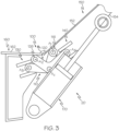
FIG. 3 is a side schematic of the hinge mechanism ofFIG. 1 in a deployed position; -
FIG. 4 is a perspective schematic of a portion of the hinge mechanism ofFIG. 1 in a deployed position; -
FIG. 5 is a perspective schematic of a portion of an aircraft with the hinge mechanism ofFIG. 1 ; -
FIG. 6 is a flow diagram of a method for hingedly coupling a flight control member to an aircraft component; -
FIG. 7 is a flow diagram of an aircraft manufacturing and service methodology; and -
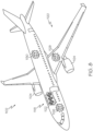
FIG. 8 is a schematic block diagram of an example of an aircraft. - The following detailed description refers to the accompanying drawings, which illustrate specific examples described by the present disclosure. Other examples having different structures and operations do not depart from the scope of the present disclosure. Like reference numerals may refer to the same feature, element, or component in the different drawings.
- Illustrative, non-exhaustive examples, which may be, but are not necessarily, claimed, of the subject matter according to the present disclosure are provided below. Reference herein to "example" means that one or more feature, structure, element, component, characteristic, and/or operational step described in connection with the example is included in at least one aspect, embodiment, and/or implementation of the subject matter according to the present disclosure. Thus, the phrases "an example," "another example," "one or more examples," and similar language throughout the present disclosure may, but do not necessarily, refer to the same example. Further, the subject matter characterizing any one example may, but does not necessarily, include the subject matter characterizing any other example. Moreover, the subject matter characterizing any one example may be, but is not necessarily, combined with the subject matter characterizing any other example.
- The disclosed hinge mechanism enables a flight control member, such as a spoiler, to rotate without the creation of cutouts in the upper panel in front of the spoiler. This also enables the panel to be effectively larger when deployed. Current solutions require cutouts for the lug to rotate up and through the panel in front of them. This creates high speed drag. Additionally, the spoiler leading edge typically must be moved aft to prevent the leading edge from rotating into the wing structure in front of it. A mechanism which re-creates the motion of a hinge but with natural gooseneck hinge features. This enables improved integration of a hinged device so that it can perform better. This motion enables the panel to be effectively larger when deployed.
- The disclosed hinge mechanism may utilize a 4-bar mechanism (paired crank sliders) that re-creates the motion of a hinge but with natural gooseneck hinge features, adapted for use in aircraft hinges such as for spoilers. 4-bar mechanism concept known and implemented in architecture, home furnishings, etc. Solves issues of leaving gaps for hinges, and enables spoiler panel moved by mechanism to have more complex motion, effectively increasing area when deployed. Adaptable to Krueger flaps and landing gear doors. There are many hinged items on the aircraft that may utilize the disclosed
hinge mechanism 100, including but not limited to spoilers, Krueger flaps, gear doors and access panels. Often the integration of the hinge causes integration constraints or other undesirable effects. This disclosed hinge mechanism enables the replication of a hingeline through a 4-bar mechanism which offers a different integration space. This can provide an expanded design space for the trajectory of the hinged item and offer a better integration space. - Referring to
FIG. 1 , disclosed is ahinge mechanism 100 for hingedly coupling aflight control member 150 to anaircraft component 160. Theflight control member 150 has atop surface 152 and may be any aerodynamic surface that is movable relative to theaircraft component 160 between at least astowed position 10 and a deployedposition 20. Theflight control member 150 may be a flight control surface. In one example, theflight control member 150 is a spoiler. In another example, theflight control member 150 is an aileron. In yet another example, theflight control member 150 is a Krueger Flap. - In one example, the
aircraft component 160 is a wing of an aircraft. In another example, theaircraft component 160 is a horizontal stabilizer of an aircraft. In yet another example, theaircraft component 160 is a rib of a wing spar. - The
hinge mechanism 100 includes afirst hinge member 110 pivotably coupled to theflight control member 150 about a first axis A1 and slidingly coupled to theaircraft component 160. In one example, thefirst hinge member 110 is coupled to theflight control member 150 with a first rotating pin joint 116. - The
first hinge member 110 and thesecond hinge member 120 are configured to cooperatively facilitate movement of theflight control member 150 relative to theaircraft component 160 between at least a stowedposition 10 and a deployedposition 20. In one example, thetop surface 152 of theflight control member 150 is substantially aligned with thetop surface 162 of theaircraft component 160 when thehinge mechanism 100 is in the stowedposition 10. In another example, thetop surface 152 of theflight control member 150 and thetop surface 162 of theaircraft component 160 define an effectively continuousaerodynamic surface 190,FIG. 1 when thehinge mechanism 100 is in the stowedposition 10. In yet a further example, thetop surface 152 of theflight control member 150 is offset from thetop surface 162 of theaircraft component 160 when thehinge mechanism 100 is in the deployedposition 20 such that thetop surface 152 of theflight control member 150 and thetop surface 162 of theaircraft component 160 define an aerodynamic angle θA,FIG. 3 . - Referring to
FIG. 1 and FIG. 2 , in one or more examples, thefirst hinge member 110 comprises afirst extension 112 and asecond extension 114 that radially extend from the central axis Ac. In one example, thefirst extension 112 and asecond extension 114 define an angle θ. The angle θ may be about 80° to about 120°. In one example, thefirst hinge member 110 is a single, monolithic structure. - Referring to
FIG. 1 , thehinge mechanism 100 further includes asecond hinge member 120 pivotably coupled to theaircraft component 160 about a second axis A2 and slidingly coupled to theflight control member 150. Thefirst hinge member 110 is pivotably coupled to thesecond hinge member 120 about a central axis Ac. In one example, thesecond hinge member 120 is coupled to theaircraft component 160 with a second rotating pin joint 126. Further, in one or more examples, thefirst hinge member 110 is pivotably rotatable about a third axis A3. Referring toFIGs. 2 and4 , in one or more examples, thehinge mechanism 100 may include more than one asecond hinge member 120 pivotably coupled to theaircraft component 160. - Referring to
FIG. 5 , thefirst hinge member 110 is pivotably coupled to thesecond hinge member 120 about a central rotating pin joint 180. The central rotating pin joint 180 rotates about the central axis AC. - Referring to
FIG. 1 , in one or more examples, thesecond hinge member 120 comprises a second hingefirst extension 122 and a second hingesecond extension 124 that radially extend from the central axis Ac. In one example, the second hingefirst extension 122 and the second hingesecond extension 124 define a second angle θ'. The second angle θ' may be about 80° to about 120°. In one example, the angle θ of thefirst hinge member 110 and second angle θ' of thesecond hinge member 120 are substantially the same. In one example, thesecond hinge member 120 is a single, monolithic structure. - Referring to
FIG. 1 , in one or more examples, thehinge mechanism 100 further includes a first slidingtrack 130 coupled to theaircraft component 160. In one example, the third axis A3 is configured to translate along the first slidingtrack 130 while thehinge mechanism 100 moves from a stowedposition 10,FIG. 1 to a deployedposition 20,FIG. 3 . - Referring to
FIG. 1 , in one or more examples, thehinge mechanism 100 further includes a second slidingtrack 140 coupled to theflight control member 150. In one example, the fourth axis A4 is configured to translate along the second slidingtrack 140. - Referring to
FIG. 1 , in one or more examples, thehinge mechanism 100 further includes anactuator 170 coupled to theflight control member 150 and theaircraft component 160. Theactuator 170 may be automated such that it automatically actuates based upon a command or may be manually actuated. In one example, theactuator 170 is a pneumatic actuator, a hydraulic actuator, or a linear actuator. Theactuator 170 may be mounted to abottom surface 154 of theflight control member 150. - Also disclosed is an
aircraft 1102,FIG. 8 , comprising thehinge mechanism 100 disclosed herein. In one or more examples, theaircraft 1102 includes anaircraft component 160, aflight control member 150 having atop surface 152 hingedly coupled to and movable relative to theaircraft component 160 having atop surface 162, and ahinge mechanism 100 coupled to theaircraft component 160 and theflight control member 150. Thehinge mechanism 100 includes afirst hinge member 110 pivotably coupled to theflight control member 150 about a first axis A1 and slidingly coupled to theaircraft component 160 and asecond hinge member 120 pivotably coupled to theaircraft component 160 about a second axis A2 and slidingly coupled to theflight control member 150. - The
flight control member 150 may be a flight control surface. In one example, theflight control member 150 is a spoiler. In another example, theflight control member 150 is an aileron. In yet another example, theflight control member 150 is a Krueger Flap. In one example, theaircraft component 160 is a wing of an aircraft. In another example, theaircraft component 160 is a horizontal stabilizer of an aircraft. In yet another example, theaircraft component 160 is a rib of a wing spar. - In one or more examples the
first hinge member 110 is pivotably coupled to thesecond hinge member 120 about a central axis Ac. Further, thefirst hinge member 110 and thesecond hinge member 120 are configured to cooperatively facilitate movement of theflight control member 150 relative to theaircraft component 160 between at least a stowedposition 10,FIG. 1 and FIG. 2 , and a deployedposition 20,FIG. 3 andFIG. 4 . - The
first hinge member 110 and thesecond hinge member 120 are configured to cooperatively facilitate movement of theflight control member 150 relative to theaircraft component 160 between at least a stowedposition 10 and a deployedposition 20. In one example, thetop surface 152 of theflight control member 150 is substantially aligned with thetop surface 162 of theaircraft component 160 when thehinge mechanism 100 is in the stowedposition 10. In another example, thetop surface 152 of theflight control member 150 and thetop surface 162 of theaircraft component 160 define an effectively continuousaerodynamic surface 190,FIG. 1 , when thehinge mechanism 100 is in the stowedposition 10. In yet a further example, thetop surface 152 of theflight control member 150 is offset from thetop surface 162 of theaircraft component 160 when thehinge mechanism 100 is in the deployedposition 20 such that thetop surface 152 of theflight control member 150 and thetop surface 162 of theaircraft component 160 define an aerodynamic angle θA,FIG. 3 . - Referring to
FIG. 6 , disclosed is amethod 200 for actuating aflight control member 150 having atop surface 152 relative to anaircraft component 160 having atop surface 162 between at least a stowedposition 10 to a deployedposition 20 with anactuator 170. In one example, theactuator 170 is a pneumatic actuator, a hydraulic actuator, or a linear actuator. Theactuator 170 may be mounted to abottom surface 154 of theflight control member 150. - Referring to
FIG. 6 , themethod 200 includes coupling 210 ahinge mechanism 100 to theflight control member 150, coupling 220 thehinge mechanism 100 to theaircraft component 160, and actuating 230 thehinge mechanism 100 between at least the stowedposition 10 and the deployedposition 20. Thecoupling 210 andcoupling 220 may include mounting thehinge mechanism 100 with any type of mechanical means or mechanical fasteners. In one example, theactuating 230 includes sliding thefirst hinge member 110 along the first slidingtrack 130 and sliding thesecond hinge member 120 along the second slidingtrack 140. - The
hinge mechanism 100 of themethod 200 includes afirst hinge member 110 pivotably coupled to theflight control member 150 about a first axis A1 and slidingly coupled to theaircraft component 160. In one example, thefirst hinge member 110 is coupled to theflight control member 150 with a first rotating pin joint 116. - Referring to
FIG. 1 , in one or more examples, thefirst hinge member 110 comprises afirst extension 112 and asecond extension 114 that radially extend from the central axis Ac. In one example, thefirst extension 112 and asecond extension 114 define an angle θ. The angle θ may be about 80° to about 120°. In one example, thefirst hinge member 110 is a single, monolithic structure. - Referring to
FIG. 1 , thehinge mechanism 100 of themethod 200 further includes asecond hinge member 120 pivotably coupled to theaircraft component 160 about a second axis A2 and slidingly coupled to theflight control member 150. Thefirst hinge member 110 is pivotably coupled to thesecond hinge member 120 about a central axis Ac. In one example, thesecond hinge member 120 is coupled to theaircraft component 160 with a second rotating pin joint 126. Further, in one or more examples, thefirst hinge member 110 is pivotably rotatable about a third axis A3. - Referring to
FIG. 5 , thefirst hinge member 110 is pivotably coupled to thesecond hinge member 120 about a central rotating pin joint 180. The central rotating pin joint 180 rotates about the central axis AC. - The
first hinge member 110 and thesecond hinge member 120 are configured to cooperatively facilitate movement of theflight control member 150 relative to theaircraft component 160 between at least a stowedposition 10 and a deployedposition 20. In one example, thetop surface 152 of theflight control member 150 is substantially aligned with thetop surface 162 of theaircraft component 160 when thehinge mechanism 100 is in the stowedposition 10. In another example, thetop surface 152 of theflight control member 150 and thetop surface 162 of theaircraft component 160 define an effectively continuousaerodynamic surface 190,FIG. 1 , when thehinge mechanism 100 is in the stowedposition 10. In yet a further example, thetop surface 152 of theflight control member 150 is offset from thetop surface 162 of theaircraft component 160 when thehinge mechanism 100 is in the deployedposition 20 such that thetop surface 152 of theflight control member 150 and thetop surface 162 of theaircraft component 160 define an aerodynamic angle θA,FIG. 3 . - Referring to
FIG. 3 , in one or more examples, thesecond hinge member 120 comprises a second hingefirst extension 122 and a second hingesecond extension 124 that radially extend from the central axis Ac. In one example, the second hingefirst extension 122 and the second hingesecond extension 124 define a second angle θ'. The second angle θ' may be about 80° to about 120°. In one example, the angle θ of thefirst hinge member 110 and second angle θ' of thesecond hinge member 120 are substantially the same. In one example, thesecond hinge member 120 is a single, monolithic structure. - Referring to
FIG. 1 , in one or more examples, thehinge mechanism 100 of themethod 200 further includes a first slidingtrack 130 coupled to theaircraft component 160. In one example, the third axis A3 is configured to translate along the first slidingtrack 130 while thehinge mechanism 100 moves from a stowedposition 10,FIG. 1 to a deployedposition 20,FIG. 3 . - Referring to
FIG. 1 , in one or more examples, thehinge mechanism 100 of themethod 200 further includes a second slidingtrack 140 coupled to theflight control member 150. In one example, the fourth axis A4 is configured to translate along the second slidingtrack 140. - Referring to
FIG. 1 , in one or more examples, thehinge mechanism 100 of themethod 200 further includes anactuator 170 coupled to theflight control member 150 and theaircraft component 160. Theactuator 170 may be automated such that it automatically actuates based upon a command or may be manually actuated. In one example, theactuator 170 is a pneumatic actuator. - Examples of the present disclosure may be described in the context of aircraft manufacturing and
service method 1100 as shown inFIG. 7 andaircraft 1102 as shown inFIG. 8 . During pre-production,service method 1100 may include specification and design (block 1104) ofaircraft 1102 and material procurement (Block 1106). During production, component and subassembly manufacturing (Block 1108) and system integration (Block 1110) ofaircraft 1102 may take place. Thereafter,aircraft 1102 may go through certification and delivery (Block 1112) to be placed in service (Block 1114). While in service,aircraft 1102 may be scheduled for routine maintenance and service (Block 1116). Routine maintenance and service may include modification, reconfiguration, refurbishment, etc. of one or more systems ofaircraft 1102. - Each of the processes of
service method 1100 may be performed or carried out by a system integrator, a third party, and/or an operator (e.g., a customer). For the purposes of this description, a system integrator may include, without limitation, any number of aircraft manufacturers and major-system subcontractors; a third party may include, without limitation, any number of vendors, subcontractors, and suppliers; and an operator may be an airline, leasing company, military entity, service organization, and so on. - As shown in
FIG. 8 ,aircraft 1102 produced byservice method 1100 may includeairframe 1118 with a plurality of high-level systems 1120 and interior 1122. Examples of high-level systems 1120 include one or more ofpropulsion system 1124,electrical system 1126,hydraulic system 1128, andenvironmental system 1130. Any number of other systems may be included. Although an aerospace example is shown, the principles disclosed herein may be applied to other industries, such as the automotive industry. Accordingly, in addition toaircraft 1102, the principles disclosed herein may apply to other vehicles, e.g., land vehicles, marine vehicles, space vehicles, etc. - Hinge mechanism(s), aircraft, and method(s) shown or described herein may be employed during any one or more of the stages of the manufacturing and
service method 1100. For example, components or subassemblies corresponding to component and subassembly manufacturing (block 1108) may be fabricated or manufactured in a manner similar to components or subassemblies produced whileaircraft 1102 is in service (Block 1114). Also, one or more examples of the hinge mechanism(s), aircraft, and method(s) or combination thereof may be utilized during production stages component and subassembly manufacturing (Block 1108) and system integration (Block 1110), for example, by substantially expediting assembly of or reducing the cost ofaircraft 1102. Similarly, one or more examples of the system or method realizations, or a combination thereof, may be utilized, for example and without limitation, whileaircraft 1102 is in service (Block 1114) and/or during maintenance and service (Block 1116). - Different examples of the hinge mechanism(s), aircraft, and method(s) disclosed herein include a variety of components, features, and functionalities. It should be understood that the various examples of the hinge mechanism(s), aircraft, and method(s) disclosed herein may include any of the components, features, and functionalities of any of the other examples of the hinge mechanism(s), aircraft, and method(s) disclosed herein in any combination, and all of such possibilities are intended to be within the scope of the present disclosure.
- Further, the disclosure comprises the subject matter described in the following clauses:
- Clause 1. A hinge mechanism for hingedly coupling a flight control member having a top surface to an aircraft component having a top surface, the hinge mechanism comprising:a first hinge member pivotably coupled to the flight control member about a first axis (A1) and slidingly coupled to the aircraft component; and a second hinge member pivotably coupled to the aircraft component about a second axis (A2) and slidingly coupled to the flight control member, wherein the first hinge member is pivotably coupled to the second hinge member about a central axis (Ac), and wherein the first hinge member and the second hinge member are configured to cooperatively facilitate movement of the flight control member relative to the aircraft component between at least a stowed position and a deployed position.
- Clause 2. The hinge mechanism of Clause 1, wherein the top surface of the flight control member is substantially aligned with the top surface of the aircraft component when the hinge mechanism is in the stowed position.
- Clause 3. The hinge mechanism of Clause 1 or Clause 2, wherein the top surface of the flight control member and the top surface of the aircraft component define an effectively continuous aerodynamic surface when the hinge mechanism is in the stowed position.
- Clause 4. The hinge mechanism of any of Clauses 1-3, wherein the top surface of the flight control member is offset from the top surface of the aircraft component when the hinge mechanism is in the deployed position such that the top surface of the flight control member and the top surface of the aircraft component define an aerodynamic angle (θA).
- Clause 5. The hinge mechanism of any of Clauses 1-4, wherein the first hinge member is coupled to the flight control member with a first rotating pin j oint.
- Clause 6. The hinge mechanism of any of Clauses 1-5, wherein the second hinge member is coupled to the aircraft component with a second rotating pin joint.
- Clause 7. The hinge mechanism of any of Clauses 1-6, wherein the first hinge member is pivotably coupled to the second hinge member about a central rotating pin joint.
- Clause 8. The hinge mechanism of any of Clauses 1-7, wherein the first hinge member comprises a first extension and a second extension that radially extend from the central axis (Ac), and wherein the first extension and a second extension define an angle (θ).
- Clause 9. The hinge mechanism of Clause 8, wherein the angle (θ) is about 80° to about 120°.
-
Clause 10. The hinge mechanism of any of Clauses 1-9, wherein the second hinge member comprises a second hinge first extension and a second hinge second extension that radially extend from the central axis (Ac), and wherein the second hinge first extension and the second hinge second extension define a second angle (θ'). - Clause 11. The hinge mechanism of
Clause 10, wherein the second angle (θ') is about 80° to about 120°. - Clause 12. The hinge mechanism of any of Clauses 1-11, wherein the first hinge member is a single, monolithic structure.
- Clause 13. The hinge mechanism of any of Clauses 1-12, wherein the second hinge member is a single, monolithic structure.
- Clause 14. The hinge mechanism of any of Clauses 1-13, further comprising a first sliding track coupled to the aircraft component.
- Clause 15. The hinge mechanism of Clause 14, wherein the first hinge member is pivotably rotatable about a third axis (A3) and wherein the third axis (A3) is configured to translate along the first sliding track.
- Clause 16. The hinge mechanism of any of Clauses 1-15, further comprising a second sliding track coupled to the flight control member.
- Clause 17. The hinge mechanism of Clause 16, wherein the second hinge member is pivotably rotatable about a fourth axis (A4) and wherein the fourth axis (A4) is configured to translate along the second sliding track.
- Clause 18. The hinge mechanism of any of Clauses 1-17, further comprising an actuator coupled to the flight control member and the aircraft component, the actuator being configured to facilitate movement of the flight control member relative to the aircraft component.
- Clause 19. The hinge mechanism of Clause 18, wherein the actuator is mounted to a bottom surface of the flight control member.
-
Clause 20. The hinge mechanism of Clause 18 or 19, wherein the actuator is a pneumatic actuator. - Clause 21. The hinge mechanism of Clause 18 or 19, wherein the actuator is a linear actuator.
- Clause 22. The hinge mechanism of Clause 18 or 19, wherein the actuator is a hydraulic actuator.
- Clause 23. The hinge mechanism of any of Clauses 1-22, wherein the flight control member is a spoiler.
- Clause 24. The hinge mechanism of any of Clauses 1-22, wherein the flight control member is an aileron.
- Clause 25. The hinge mechanism of any of Clauses 1-22, wherein the flight control member is a Krueger Flap.
- Clause 26. The hinge mechanism of any of Clauses 1-25, wherein the aircraft component is a wing of an aircraft.
- Clause 27. The hinge mechanism of any of Clauses 1-25, wherein the aircraft component is a horizontal stabilizer of an aircraft.
- Clause 28. The hinge mechanism of any of Clauses 1-25, wherein the aircraft component is a rib of a wing spar.
- Clause 29. An aircraft comprising: an aircraft component; a flight control member having a top surface hingedly coupled to and movable relative to the aircraft component having a top surface; and a hinge mechanism coupled to the aircraft component and the flight control member, the hinge mechanism comprising: a first hinge member pivotably coupled to the flight control member about a first axis (A1) and slidingly coupled to the aircraft component; and a second hinge member pivotably coupled to the aircraft component about a second axis (A2) and slidingly coupled to the flight control member, wherein the first hinge member is pivotably coupled to the second hinge member about a central axis (Ac), and wherein the first hinge member and the second hinge member) are configured to cooperatively facilitate movement of the flight control member relative to the aircraft component between at least a stowed position and a deployed position.
- Clause 29a. An aircraft comprising: an aircraft component; a flight control member having a top surface hingedly coupled to and movable relative to the aircraft component having a top surface; and the hinge mechanism of any of Clauses 1-28, wherein the hinge mechanism is coupled to the aircraft component and the flight control member.
- Clause 30. The aircraft of Clause 29 or Clause 29a, wherein the top surface of the flight control member is substantially aligned with the top surface of the aircraft component when the hinge mechanism is in the stowed position.
- Clause 31. The aircraft of any of Clauses 29-30, wherein the top surface of the flight control member and the top surface of the aircraft component define an effectively continuous aerodynamic surface when the hinge mechanism is in the stowed position.
- Clause 32. The aircraft of any of Clauses 29-31, wherein the top surface of the flight control member is offset from the top surface of the aircraft component when the hinge mechanism is in the deployed position such that the top surface of the flight control member and the top surface of the aircraft component define an aerodynamic angle (θA).
- Clause 33. The aircraft of any of Clauses 29-32, wherein the first hinge member is coupled to the flight control member with a first rotating pin joint.
- Clause 34. The aircraft of any of Clauses 29-33, wherein the second hinge member is coupled to the aircraft component with a second rotating pin joint.
- Clause 35. The aircraft of any of Clauses 29-34, wherein the first hinge member is pivotably coupled to the second hinge member about a central rotating pin joint.
- Clause 36. The aircraft of any of Clauses 29-35, wherein the first hinge member comprises a first extension and a second extension that radially extend from the central axis (Ac), and wherein the first extension and a second extension define an angle (θ).
- Clause 37. The aircraft of Clause 36, wherein the angle (θ) is about 80° to about 120°.
- Clause 38. The aircraft of any of Clauses 29-37, wherein the second hinge member comprises a second hinge first extension and a second hinge second extension that radially extend from the central axis (Ac), and wherein the second hinge first extension and the second hinge second extension define a second angle (θ').
- Clause 39. The aircraft of Clause 38, wherein the second angle (θ') is about 80° to about 120°.
- Clause 40. The aircraft of any of Clauses 29-39, wherein the first hinge member is a single, monolithic structure.
- Clause 41. The aircraft of any of Clauses 29-40, wherein the second hinge member is a single, monolithic structure.
- Clause 42. The aircraft of any of Clauses 29-41, further comprising a first sliding track coupled to the aircraft component.
- Clause 43. The aircraft of Clause 42, wherein the first hinge member is pivotably rotatable about a third axis (A3) and wherein the third axis (A3) is configured to translate along the first sliding track.
- Clause 44. The aircraft of any of Clauses 29-43, further comprising a second sliding track coupled to the flight control member.
- Clause 45. The aircraft of Clause 44, wherein the second hinge member is pivotably rotatable about a fourth axis (A4) and wherein the fourth axis (A4) is configured to translate along the second sliding track.
- Clause 46. A method for actuating a flight control member having a top surface relative to an aircraft component having a top surface between at least a stowed position to a deployed position with an actuator, the method comprising: coupling a hinge mechanism to the flight control member; coupling the hinge mechanism to the aircraft component; and actuating the hinge mechanism between at least the stowed position and the deployed position, the hinge mechanism comprising: a first hinge member pivotably coupled to the flight control member about a first axis (A1) and slidingly coupled to the aircraft component; a second hinge member pivotably coupled to the aircraft component about a second axis (A2) and slidingly coupled to the flight control member; a first sliding track coupled to the aircraft component; and a second sliding track coupled to the flight control member wherein the first hinge member is pivotably coupled to the second hinge member about a central axis (Ac), and wherein the first hinge member and the second hinge member are configured to cooperatively facilitate movement of the flight control member relative to the aircraft component between at least a stowed position and a deployed position.
- Clause 47. The method of Clause 46, wherein the actuating comprises sliding the first hinge member along the first sliding track and sliding the second hinge member along the second sliding track.
- Clause 48. The method of Clause 46 or 47, wherein the first hinge member is coupled to the flight control member with a first rotating pin joint.
- Clause 49. The method of any of Clauses 46-48, wherein the second hinge member is coupled to the aircraft component with a second rotating pin joint.
- Clause 50. The method of any of Clauses 46-49, wherein the first hinge member is pivotably coupled to the second hinge member about a central rotating pin joint.
- Clause 51. The method of any of Clauses 46-50, wherein the first hinge member comprises a first extension and a second extension, and wherein the first extension and a second extension define an angle (Θ).
- Clause 52. The method of any of Clauses 46-51, wherein the second hinge member comprises a second hinge first extension and a second hinge second extension , and wherein the second hinge first extension and the second hinge second extension define a second angle (θ').
- Clause 53. The method of any of Clauses 46-52, wherein the first hinge member is a single, monolithic structure.
- Clause 54. The method of any of Clauses 46-53, wherein the second hinge member is a single, monolithic structure.
- Clause 55. The method of any of Clauses 46-54, wherein the first hinge member is pivotably rotatable about a third axis (A3) and wherein the third axis (A3) is configured to translate along the first sliding track.
- Clause 56. The method of any of Clauses 46-55, wherein the second hinge member is pivotably rotatable about a fourth axis (A4) and wherein the fourth axis (A4) is configured to translate along the second sliding track.
- Clause 57. The method of any of Clauses 46-56, wherein the hinge mechanism is a hinge mechanism according to any of Clauses 1-28.
- Many modifications of examples set forth herein will come to mind to one skilled in the art to which the present disclosure pertains having the benefit of the teachings presented in the foregoing descriptions and the associated drawings.
- Therefore, it is to be understood that the present disclosure is not to be limited to the specific examples illustrated and that modifications and other examples are intended to be included within the scope of the appended claims. Moreover, although the foregoing description and the associated drawings describe examples of the present disclosure in the context of certain illustrative combinations of elements and/or functions, it should be appreciated that different combinations of elements and/or functions may be provided by alternative implementations without departing from the scope of the appended claims. Accordingly, parenthetical reference numerals in the appended claims are presented for illustrative purposes only and are not intended to limit the scope of the claimed subject matter to the specific examples provided in the present disclosure.
Claims (15)
- A hinge mechanism (100) for hingedly coupling a flight control member (150) having a top surface (152) to an aircraft component (160) having a top surface (162), the hinge mechanism (100) comprising:a first hinge member (110) pivotably coupled to the flight control member (150) about a first axis (A1) and slidingly coupled to the aircraft component (160); anda second hinge member (120) pivotably coupled to the aircraft component (160) about a second axis (A2) and slidingly coupled to the flight control member (150),wherein the first hinge member (110) is pivotably coupled to the second hinge member (120) about a central axis (Ac), andwherein the first hinge member (110) and the second hinge member (120) are configured to cooperatively facilitate movement of the flight control member (150) relative to the aircraft component (160) between at least a stowed position (10) and a deployed position (20).
- The hinge mechanism (100) of Claim 1, wherein the top surface (152) of the flight control member (150) is substantially aligned with the top surface (162) of the aircraft component (160) when the hinge mechanism (100) is in the stowed position (10).
- The hinge mechanism (100) of Claim 1 or 2, wherein the top surface (152) of the flight control member (150) and the top surface (162) of the aircraft component (160) define an effectively continuous aerodynamic surface (190) when the hinge mechanism (100) is in the stowed position (10).
- The hinge mechanism (100) of any preceding Claim, wherein the top surface (152) of the flight control member (150) is offset from the top surface (162) of the aircraft component (160) when the hinge mechanism (100) is in the deployed position (20) such that the top surface (152) of the flight control member (150) and the top surface (162) of the aircraft component (160) define an aerodynamic angle (θA).
- The hinge mechanism (100) of any preceding Claim, wherein the first hinge member (110) comprises a first extension (112) and a second extension (114) that radially extend from the central axis (AC), and wherein the first extension (112) and a second extension (114) define an angle (θ).
- The hinge mechanism (100) of any preceding Claim, further comprising a first sliding track (130) coupled to the aircraft component (160).
- The hinge mechanism (100) of Claim 6, wherein the first hinge member (110) is pivotably rotatable about a third axis (A3) and wherein the third axis (A3) is configured to translate along the first sliding track (130).
- The hinge mechanism (100) of any preceding Claim, further comprising an actuator (170) coupled to the flight control member (150) and the aircraft component (160), the actuator (170) being configured to facilitate movement of the flight control member (150) relative to the aircraft component (160).
- The hinge mechanism (100) of Claim 8, wherein the actuator (170) is mounted to a bottom surface (154) of the flight control member (150).
- An aircraft (1102) comprising:an aircraft component (160);a flight control member (150) having a top surface (152) hingedly coupled to and movable relative to the aircraft component (160) having a top surface (162); andthe hinge mechanism (100) of any preceding Claim, wherein the hinge mechanism (100) is coupled to the aircraft component (160) and the flight control member (150).
- A method (200) for actuating a flight control member (150) having a top surface (152) relative to an aircraft component (160) having a top surface (162) between at least a stowed position (10) to a deployed position (20) with an actuator (170), the method (200) comprising:coupling (210) a hinge mechanism (100) to the flight control member (150);coupling (220) the hinge mechanism (100) to the aircraft component (160); andactuating (230) the hinge mechanism (100) between at least the stowed position (10) and the deployed position (20), the hinge mechanism (100) comprising:a first hinge member (110) pivotably coupled to the flight control member (150) about a first axis (A1) and slidingly coupled to the aircraft component (160);a second hinge member (120) pivotably coupled to the aircraft component (160) about a second axis (A2) and slidingly coupled to the flight control member (150);a first sliding track (130) coupled to the aircraft component (160); anda second sliding track (140) coupled to the flight control member (150)wherein the first hinge member (110) is pivotably coupled to the second hinge member (120) about a central axis (Ac), andwherein the first hinge member (110) and the second hinge member (120) are configured to cooperatively facilitate movement of the flight control member (150) relative to the aircraft component (160) between at least a stowed position (10) and a deployed position (20).
- The method of Claim 11, wherein the actuating (230) comprises sliding the first hinge member (110) along the first sliding track (130) and sliding the second hinge member (120) along the second sliding track (140).
- The method (200) of Claim 11 or 12, wherein the first hinge member (110) is coupled to the flight control member (150) with a first rotating pin joint (116).
- The method (200) of any of Claims 11-13, wherein the first hinge member (110) comprises a first extension (112) and a second extension (114), and wherein the first extension (112) and a second extension (114) define an angle (Θ).
- The method (200) of any of claims 11-14, wherein the first hinge member (110) is pivotably rotatable about a third axis (A3) and wherein the third axis (A3) is configured to translate along the first sliding track (130).
Applications Claiming Priority (1)
| Application Number | Priority Date | Filing Date | Title |
|---|---|---|---|
| US17/661,588 US11873094B2 (en) | 2022-05-02 | 2022-05-02 | Hinge mechanisms for coupling flight control members to aircraft components and associated methods |
Publications (1)
| Publication Number | Publication Date |
|---|---|
| EP4273038A1 true EP4273038A1 (en) | 2023-11-08 |
Family
ID=85381347
Family Applications (1)
| Application Number | Title | Priority Date | Filing Date |
|---|---|---|---|
| EP23158206.5A Pending EP4273038A1 (en) | 2022-05-02 | 2023-02-23 | Hinge mechanisms for coupling flight control members to aircraft components and associated methods |
Country Status (2)
| Country | Link |
|---|---|
| US (1) | US11873094B2 (en) |
| EP (1) | EP4273038A1 (en) |
Citations (3)
| Publication number | Priority date | Publication date | Assignee | Title |
|---|---|---|---|---|
| GB734446A (en) * | 1953-03-20 | 1955-08-03 | Armstrong Whitworth Co Eng | Operating the flaps of aircraft wings |
| US20110135472A1 (en) * | 2009-11-10 | 2011-06-09 | Airbus Operations (S.A.S) | Aerodynamic flight control surface said of crocodile style for aircraft |
| US10538303B2 (en) * | 2017-06-29 | 2020-01-21 | The Boeing Company | Systems and methods for linkage controlling access panel on commercial aircraft |
Family Cites Families (7)
| Publication number | Priority date | Publication date | Assignee | Title |
|---|---|---|---|---|
| US7766282B2 (en) * | 2007-12-11 | 2010-08-03 | The Boeing Company | Trailing edge device catchers and associated systems and methods |
| US8511608B1 (en) * | 2010-11-15 | 2013-08-20 | The Boeing Company | Trailing edge flap system |
| US9878774B2 (en) | 2014-09-19 | 2018-01-30 | The Boeing Company | System and method for operating a droop panel using a pin joint linkage assembly |
| US11097829B2 (en) | 2018-04-13 | 2021-08-24 | The Boeing Company | Methods and apparatus to control camber |
| US10737761B2 (en) | 2018-04-19 | 2020-08-11 | The Boeing Company | Camber adjustment systems and methods for aircraft wings |
| US11059563B2 (en) | 2018-09-06 | 2021-07-13 | The Boeing Company | Collapsible flap deployment system for a wing of an aircraft |
| US11254417B2 (en) | 2018-12-11 | 2022-02-22 | The Boeing Company | Multi-section spoiler |
-
2022
- 2022-05-02 US US17/661,588 patent/US11873094B2/en active Active
-
2023
- 2023-02-23 EP EP23158206.5A patent/EP4273038A1/en active Pending
Patent Citations (3)
| Publication number | Priority date | Publication date | Assignee | Title |
|---|---|---|---|---|
| GB734446A (en) * | 1953-03-20 | 1955-08-03 | Armstrong Whitworth Co Eng | Operating the flaps of aircraft wings |
| US20110135472A1 (en) * | 2009-11-10 | 2011-06-09 | Airbus Operations (S.A.S) | Aerodynamic flight control surface said of crocodile style for aircraft |
| US10538303B2 (en) * | 2017-06-29 | 2020-01-21 | The Boeing Company | Systems and methods for linkage controlling access panel on commercial aircraft |
Also Published As
| Publication number | Publication date |
|---|---|
| US11873094B2 (en) | 2024-01-16 |
| US20230348040A1 (en) | 2023-11-02 |
Similar Documents
| Publication | Publication Date | Title |
|---|---|---|
| EP2676878B1 (en) | Swing tip assembly rotation joint | |
| CA2858111C (en) | Swing wing tip system, assembly and method with dual load path structure | |
| EP2669190B2 (en) | Rotary actuated high lift gapped aileron | |
| US8511608B1 (en) | Trailing edge flap system | |
| US8382045B2 (en) | Shape-changing control surface | |
| AU2017218981B2 (en) | Aircraft wings, aircraft, and related methods | |
| US11858629B2 (en) | Sliding panel for download alleviation on high-speed VTOL aircraft | |
| US12179919B2 (en) | Slat movement system for aircraft | |
| US10793252B2 (en) | Apparatus and method for covering an opening in an aircraft | |
| EP4273038A1 (en) | Hinge mechanisms for coupling flight control members to aircraft components and associated methods | |
| US12269593B2 (en) | Wing assemblies and aircraft | |
| US12043386B2 (en) | Wing assemblies and aircraft | |
| EP4400414B1 (en) | Underwing-mounted trailing edge bifold flaps for wings of aircraft | |
| US11884394B2 (en) | Wing assemblies with tandemly actuated flight control surfaces, aircraft, and related methods | |
| US12097959B2 (en) | Underwing-mounted trailing edge flaps for wings of aircraft | |
| Neittaanmäki et al. | AERODYNAMIC DESIGN OF AIRBUS HIGH-LIFT WINGS IN A MULTIDISCIPLINARY ENVIRONMENT |
Legal Events
| Date | Code | Title | Description |
|---|---|---|---|
| PUAI | Public reference made under article 153(3) epc to a published international application that has entered the european phase |
Free format text: ORIGINAL CODE: 0009012 |
|
| STAA | Information on the status of an ep patent application or granted ep patent |
Free format text: STATUS: THE APPLICATION HAS BEEN PUBLISHED |
|
| AK | Designated contracting states |
Kind code of ref document: A1 Designated state(s): AL AT BE BG CH CY CZ DE DK EE ES FI FR GB GR HR HU IE IS IT LI LT LU LV MC ME MK MT NL NO PL PT RO RS SE SI SK SM TR |
|
| STAA | Information on the status of an ep patent application or granted ep patent |
Free format text: STATUS: REQUEST FOR EXAMINATION WAS MADE |
|
| 17P | Request for examination filed |
Effective date: 20240508 |
|
| RBV | Designated contracting states (corrected) |
Designated state(s): AL AT BE BG CH CY CZ DE DK EE ES FI FR GB GR HR HU IE IS IT LI LT LU LV MC ME MK MT NL NO PL PT RO RS SE SI SK SM TR |
|
| STAA | Information on the status of an ep patent application or granted ep patent |
Free format text: STATUS: EXAMINATION IS IN PROGRESS |
|
| RIC1 | Information provided on ipc code assigned before grant |
Ipc: F16C 11/04 20060101ALI20250226BHEP Ipc: B64C 9/02 20060101AFI20250226BHEP |
|
| 17Q | First examination report despatched |
Effective date: 20250313 |
|
| GRAP | Despatch of communication of intention to grant a patent |
Free format text: ORIGINAL CODE: EPIDOSNIGR1 |
|
| STAA | Information on the status of an ep patent application or granted ep patent |
Free format text: STATUS: GRANT OF PATENT IS INTENDED |
|
| INTG | Intention to grant announced |
Effective date: 20260306 |