EP4272985A1 - Packaging spacebox for fuel cells - Google Patents
Packaging spacebox for fuel cells Download PDFInfo
- Publication number
- EP4272985A1 EP4272985A1 EP23171915.4A EP23171915A EP4272985A1 EP 4272985 A1 EP4272985 A1 EP 4272985A1 EP 23171915 A EP23171915 A EP 23171915A EP 4272985 A1 EP4272985 A1 EP 4272985A1
- Authority
- EP
- European Patent Office
- Prior art keywords
- storage unit
- truck
- chassis beams
- trailer combination
- combination according
- Prior art date
- Legal status (The legal status is an assumption and is not a legal conclusion. Google has not performed a legal analysis and makes no representation as to the accuracy of the status listed.)
- Granted
Links
Images


Classifications
-
- B—PERFORMING OPERATIONS; TRANSPORTING
- B60—VEHICLES IN GENERAL
- B60K—ARRANGEMENT OR MOUNTING OF PROPULSION UNITS OR OF TRANSMISSIONS IN VEHICLES; ARRANGEMENT OR MOUNTING OF PLURAL DIVERSE PRIME-MOVERS IN VEHICLES; AUXILIARY DRIVES FOR VEHICLES; INSTRUMENTATION OR DASHBOARDS FOR VEHICLES; ARRANGEMENTS IN CONNECTION WITH COOLING, AIR INTAKE, GAS EXHAUST OR FUEL SUPPLY OF PROPULSION UNITS IN VEHICLES
- B60K1/00—Arrangement or mounting of electrical propulsion units
- B60K1/04—Arrangement or mounting of electrical propulsion units of the electric storage means for propulsion
- B60K2001/0405—Arrangement or mounting of electrical propulsion units of the electric storage means for propulsion characterised by their position
- B60K2001/0438—Arrangement under the floor
-
- B—PERFORMING OPERATIONS; TRANSPORTING
- B60—VEHICLES IN GENERAL
- B60Y—INDEXING SCHEME RELATING TO ASPECTS CROSS-CUTTING VEHICLE TECHNOLOGY
- B60Y2200/00—Type of vehicle
- B60Y2200/10—Road Vehicles
- B60Y2200/14—Trucks; Load vehicles, Busses
-
- B—PERFORMING OPERATIONS; TRANSPORTING
- B60—VEHICLES IN GENERAL
- B60Y—INDEXING SCHEME RELATING TO ASPECTS CROSS-CUTTING VEHICLE TECHNOLOGY
- B60Y2200/00—Type of vehicle
- B60Y2200/10—Road Vehicles
- B60Y2200/14—Trucks; Load vehicles, Busses
- B60Y2200/142—Heavy duty trucks
-
- Y—GENERAL TAGGING OF NEW TECHNOLOGICAL DEVELOPMENTS; GENERAL TAGGING OF CROSS-SECTIONAL TECHNOLOGIES SPANNING OVER SEVERAL SECTIONS OF THE IPC; TECHNICAL SUBJECTS COVERED BY FORMER USPC CROSS-REFERENCE ART COLLECTIONS [XRACs] AND DIGESTS
- Y02—TECHNOLOGIES OR APPLICATIONS FOR MITIGATION OR ADAPTATION AGAINST CLIMATE CHANGE
- Y02T—CLIMATE CHANGE MITIGATION TECHNOLOGIES RELATED TO TRANSPORTATION
- Y02T90/00—Enabling technologies or technologies with a potential or indirect contribution to GHG emissions mitigation
- Y02T90/40—Application of hydrogen technology to transportation, e.g. using fuel cells
Definitions
- the invention relates to vehicles with alternative fuel sources, in particular vehicles using pressurised fuel sources such as hydrogen gas, liquid hydrogen or other fuels in gas or liquid form.
- Trucks in general are used to transport heavy loads over long distances.
- tractor semi-trailer combinations are used in which the tractor vehicle pulls and partly supports the payload that is packed onto the semi-trailer.
- Fuel cell devices are typically designed as complete charge generating systems, wherein, additional to one or more charge generating portions, also referred to as fuel cell stacks; one or more auxiliary portions to control hydrogen and air flow to the generating portion, also referred to as Balance-of-Plant (BOP), are provided.
- auxiliary portions at least comprise pump units, and air compressor and cooling units, to keep the fuel cell in a proper conditioned form as well as DC-DC converters to connect the fuel cell stack to the high voltage battery system to compensate this electrical interconnection for voltage differences and fluctuations in the actual fuel cell generating portion.
- the fuel cells may well be sensitive to acceleration impact, which could damage the charge generating portions, in particular the membrane and/or auxiliary portions when not specifically designed for the harsh vehicle environment of a vibrating truck chassis.
- a truck or tractor semi-trailer combination comprises an electrical driveline, an electric energy storage battery system, hydrogen storage system and a plurality of fuel cell devices.
- Each fuel cell device comprises a charge generating portion; and one or more auxiliary portions auxiliary to the charge generating portion.
- the truck is provided with a pair of elongated chassis beams extending along the length of the truck, wherein a storage space is defined between the chassis beams; a front side bridge member laterally extending across the chassis beams; and a rear side cross beam.
- At least one storage unit is provided that houses a fuel cell device, comprising one or more mounts for suspending said storage unit relative to the chassis beams.
- the storage unit further comprises an interface module for coupling an air supply duct, an hydrogen supply duct and a water drain duct.
- the storage unit has a top part extending between the chassis beams in said storage space; and a bottom part extending below the chassis beams and extending at least on one side laterally across the chassis beams.
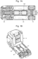
- Figure 1 shows a realistic embodiment of a truck (or tractor), wherein a storage space 100 is defined between the chassis beams; a front side bridge member laterally extending across the chassis beams; and a rear side cross beam an additional elongated pressure vessel 34 is oriented in horizontal position adjacent the at least one pressure vessel 3 in upstanding position and in near vicinity of the projected fifth wheel location; above the chassis members.
- the position of the pressure vessels is beneficial due to the efficient use of space, but not mandatory; other spaces may be suitable.
- a pressure vessel 34 is preferably located below on a (projected) bottom of the semi-trailer at the vertical location of the fifth wheel and above the tractor chassis members.
- additional elongated pressure vessels 33 for reaching a driving range of more than 800 km or more, are provided in the bottom framework (or chassis) of the tractor, in particular, in a space provided between front and rear wheels and at the outside (in parallel to the longitudinal centreline of the tractor) where normally, in conventional combustion engine driven trucks, the diesel tanks and the exhaust aftertreatment system are installed.
- a battery pack 50 that realistically weighs at least about 500 - 1500 kgs, may preferably be placed with its gravity centre on or near the front axle, as this is considered to be the heaviest component (highest gravimetric density) in a fuel cell electric vehicle to allow for more payload carry ability of the rear axle. Note that the maximum axle loads are legally bounded (e.g.
- the center space in the bottom of the tractor and in the middle between the chassis members may be used for housing fuel cell systems 51, where normally, in conventional trucks, central drive shafts or trains may be housed.
- the electric motors that drive the truck may be arranged as a so-called e-axle 70 (having the electric motors directly integrated in the rigid rear axle advantageously eliminating the need for a central driveshaft and differential gear system with a complex angle transmission), advantageously making packaging space available to place the fuel cells in the middle of the chassis.
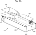
- FIG 2A shows a storage unit 200 provided in the storage space indicated in FIG 1A .
- the storage unit houses a fuel cell device (not shown) and comprises one or more mounts 130 for suspending said storage unit relative to the chassis beams 20.
- the storage unit 200 further comprises an interface module 220 e.g. for coupling an air supply duct, an hydrogen supply duct and a water drain duct (see subsequent figures).
- a virtual plane 255 divides a top part 250 extending between the chassis beams 20 in said storage space 100; and a bottom part 260 extending below the chassis beams and extending at least on one side laterally across the chassis beams 20.
- storage unit 200 may be suspended on each side in length direction to one or more of these cross beams.
- FIG 2A shows storage unit 200 provided extending underneath a middle cross beam 221 (in the art known as K-cross member).
- four mounts are arranged to carry said storage unit, having two front mounts 131 in an extended lateral position on a storage unit front side, and two rear mounts 130 in an adjacent position on a storage unit rear side.
- the two front mounts 130 at the adjacent rear side position are preferably placed close to each other (short lateral distance) to mimic the functionality of a so-called three point suspension advantageously absorbing chassis torsional flex deformation without dynamically loading these mounts.
- the storage unit is elastically suspended with a heave, pitch and roll eigenfrequency that is tuned to be distinct of the primary eigenfrequency typically ranging between 10 and 17 Hz of the rear axle unsprung mass. This can for example be achieved by a ratio of the axial stiffness and the lateral stiffness is more than 5, preferably more than 8, or even in a range of 10-30.
- a fairly rigid mounting structure of the hydrogen vessels may be placed behind the cabin, being close the front end of the storage box.
- This can be advantageous for relatively heavy storage box weights, e.g. exceeding 600 kg, so that the risk of picking up vibrations from the unsprung mass are low if a stiff mount is used, with stiffness eg. higher than 8000 N/mm in the front. This improves mounting characteristics for mounting the air supply, hydrogen supply and water drain.
- the rear end of the storage box may be mounted with a stiffness that is relatively lower, e.g. lower than 8000 N/mm, in particular between 3000 and 8000 N/mm to accommodate some torsional and vertical vibration. This has an advantage that a very stable interface can be provided for the storage box and while having a low vibrational impact.
- a single integrated double suspension mount provides an advantage that impact of the rear wheels is only partly translated in a torsional rotational movement of the storage unit 200 along an axis that aligns with the vehicles length direction.
- chassis torsion between chassis members 20 and the storage unit 200 can be minimized, which is beneficial for the position of the depicted interface module 220, that benefits from a stable connection between the storage unit 200 and corresponding coupling of an air supply duct, an hydrogen supply duct and a water drain duct to the storage unit 200.
- all mounts are provided on the interior of the storage space, that means, not extending at least not laterally, to provide room for horizontal hydrogen vessels 33 (see FIG 1 ).
- a bridge member may also be formed by a cross beam, as long as it provides a lateral connection between the chassis beams 20.
- the rear suspension cross member 220 may be part of a larger structure, e.g. a suspension structure for the rear axle.
- the storage unit 200 may be formed extending into said storage space 100 with an L-shape or an inverted T-shape.
- a T-shape has the advantage of a greater energy generating volume in the space 260 underneath the chassis beams 20; while a L-shape (effectively using only one lateral extending side underneath the chassis beams 20) may provide for additional air ducts sideways connecting to the storage unit, or additional high voltage cabling or other tubing that needs to be guided alongside the storage units 200.
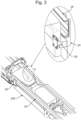
- Figure 3 shows an alternative mount structure, with L-shaped brackets 22 mounted to the chassis beams 20.
- Section A is shown partly enlarged and rotated, so that it is visible that front mounts 131 are supported on a bottom leg of the L-shaped bracket 22 to carry the weight of the storage unit 200 acting on said mounts 131 (in closed form manner opposing of gravity).
- This has the advantage that the storage unit 200 is still supported by the L-shaped bracket 22 in an inadverted event of failure of the mount 130, such as loosening of the fixation bolts.
- the storage unit 200 can be efficiently removed by removing the L-shaped brackets 22 from the chassis beams 22 and lowering the storage unit 200.
- the structure does not have protruding elements that could interfere with system components (e.g. battery elements or hydrogen tanks) mounted lateral to the storage unit 200.
- system components e.g. battery elements or hydrogen tanks
- Figure 4 shows several configuration layouts for the storage unit 200-1, 200-2, 200-3.
- storage unit 200-1 comprises at least one auxiliary fuel cell portion 255 shaped to at least extend partly in the storage unit top part 250, and wherein one or more charge generating portions 270, also known as fuel cell stacks are provided in the storage unit bottom part 260.
- the auxiliary fuel cell portion is also known as the balance of plant (BOP) and typically comprises water pumps, inverters, control units, humidifier, etc. Additionally are show DC-DC converters 256, air compressor 257 and intercooler 258 as exemplary components of the auxiliary fuel cell portion 255.
- BOP balance of plant
- Fig 4A houses a 4 x 75 kW Fuel Cell stack 270 in the lower part 260 that extend laterally across chassis beams 20.
- An advantage of this configuration is that the fuel stacks can be reached in by supply and drain tubing (hydrogen, air, water) in the top part 250 fairly conveniently.
- storage unit 200-2 comprises at least one charge generating portion (fuel cell stack) 270 shaped to at least extend partly in the storage unit top part 250.
- the auxiliary portions 255-1, 255-2 are provided at least on one side of the charge generating fuel cell portion 270 in the storage unit bottom part 260.
- the fuel cell stack 270 is formed by two stacked fuel cells, one of them extending between the chassis beams (not shown); and two additional stacked cells on opposite sides of a storage space portion 261 extending underneath a further central cross beam.
- a stack 270-1..4 extends in the length direction of the vehicle, with each fuel cell extending in the storage unit top part 250.
- FIG. 5 in more details shows an exemplary arrangement where it becomes clear how the interface module, provided on a top front side of the storage unit connects to an air supply duct 450 from an air intake system 400.
- air duct 450 is provided by a wide diameter/low resistance duct that connects to an air intake 470 on the front side of the truck via filter 460 that is positioned in the front right end corner of the truck in front of the front wheels and below and outsides (in lateral direction) of the chassis beams..
- a relatively large volume is occupied by such a dedicated (serviceable) filter unit to minimize the resistance to air flow through the filter itself.
- the spot in the right front bottom corner of the truck is beneficial to avoid clearance problems with other needed vehicle components. From this location on a channel system back up making the connection an air intake duct (connection with exterior) to a higher position integrated in top region of the front grille needs to be installed whilst avoiding resistance.
- Figure 5B shows how air duct connects to the interface module 220 of the storage unit.
- additional arrangements may be provided to provide for water exhausts 455, hydrogen inlets, coolant tubing and high-voltage connections (not shown).
- Exemplary design rates for the air duct may be to provide for air flow rates up to 500 g/s at ambient temperature and atmospheric pressure.
- the main channel resistance will then be caused by an air filter, which may induce pressure differences up to 5 kPa (in end of service life state and despite the fairly large volume filter unit).
- Figure 6 further shows a truck wherein the water drain duct 550 extends along the vertical elongated hydrogen vessels 3; preferably having the water drain duct integrated in a cowl 600 enclosing the vertical elongated hydrogen vessels.
Landscapes
- Engineering & Computer Science (AREA)
- Chemical & Material Sciences (AREA)
- Combustion & Propulsion (AREA)
- Transportation (AREA)
- Mechanical Engineering (AREA)
- Fuel Cell (AREA)
Abstract
Description
- The invention relates to vehicles with alternative fuel sources, in particular vehicles using pressurised fuel sources such as hydrogen gas, liquid hydrogen or other fuels in gas or liquid form.
- Of particular interest are heavy load vehicles such as trucks. Trucks in general are used to transport heavy loads over long distances. Particularly in case of heavy duty long applications so-called tractor semi-trailer combinations are used in which the tractor vehicle pulls and partly supports the payload that is packed onto the semi-trailer.
- The long travelling distances with a target of more than 500 km, of these typical long haulage tractor semi-trailer combinations require large amounts of fuel on board of the vehicle. Especially when alternative fuel sources are used such as hydrogen, the ability to carry sufficient quantities of fuel becomes even more important due to the fairly poor volumetric energy density in comparison to conventional fossil fuels (like diesel). Even more challenging becomes a layout wherein sufficient power is available, for extended periods of time, for a long-haul truck or tractor semi-trailer combination comprising an electrical driveline, an electric energy storage battery system, a hydrogen storage system and a plurality of fuel cell devices.
- To increase the volumetric energy density of these hydrogen based fuels normally gaseous hydrogen is pressurized and put into robust thick walled cylindrical container units that can withstand these high internal pressures. Pressure ranges typically from several bars in cryogenic conditions, to about 350-700 bar for storage at room temperature. To minimize the weight penalty of a firm and heavy high pressure resistant tank construction so called class IV carbon fibre reinforced plastic tanks are applied. These cylindrically shaped plastic tanks provide a new challenge for the commercial vehicle manufacturing industry to install these tank units on their trucks as replacement for the well-known rectangular sheet metal manufactured ambient pressure filled diesel tanks in the quest to offer sufficient driving range without the need for intermediate refuelling stops at gasoline shops (with currently lacking refuelling infrastructure). These large volume hydrogen tank units are typically placed left and right of the chassis (in between the front and rear wheels) and behind the cabin wall (in front of the semi-trailer). As a consequence only the remaining space in between and below the chassis rails is available to accommodate the electrical driveline, an electric energy storage battery system and a plurality of fuel cell devices.
- Fuel cell devices are typically designed as complete charge generating systems, wherein, additional to one or more charge generating portions, also referred to as fuel cell stacks; one or more auxiliary portions to control hydrogen and air flow to the generating portion, also referred to as Balance-of-Plant (BOP), are provided. Such auxiliary portions at least comprise pump units, and air compressor and cooling units, to keep the fuel cell in a proper conditioned form as well as DC-DC converters to connect the fuel cell stack to the high voltage battery system to compensate this electrical interconnection for voltage differences and fluctuations in the actual fuel cell generating portion. The fuel cells may well be sensitive to acceleration impact, which could damage the charge generating portions, in particular the membrane and/or auxiliary portions when not specifically designed for the harsh vehicle environment of a vibrating truck chassis. In addition, due to the charge generating process, substantial packaging space is needed in order to allow for generating electric output power of at least 150 kW; and preferably even multiples thereof, up to even 800 kW. This poses challenges for proper packaging of fuel cells in vicinity of a large volume hydrogen storage.
- It is an objective of the claimed invention to solve one or more problems faced in the state of the art.
- According to the invention, a truck or tractor semi-trailer combination comprises an electrical driveline, an electric energy storage battery system, hydrogen storage system and a plurality of fuel cell devices. Each fuel cell device comprises a charge generating portion; and one or more auxiliary portions auxiliary to the charge generating portion. The truck is provided with a pair of elongated chassis beams extending along the length of the truck, wherein a storage space is defined between the chassis beams; a front side bridge member laterally extending across the chassis beams; and a rear side cross beam. At least one storage unit is provided that houses a fuel cell device, comprising one or more mounts for suspending said storage unit relative to the chassis beams. The storage unit further comprises an interface module for coupling an air supply duct, an hydrogen supply duct and a water drain duct. The storage unit has a top part extending between the chassis beams in said storage space; and a bottom part extending below the chassis beams and extending at least on one side laterally across the chassis beams.
- The invention will further be elucidated by description of some specific embodiments thereof, making reference to the attached drawings. The detailed description provides examples of possible implementations of the invention, but is not to be regarded as describing the only embodiments falling under the scope. The scope of the invention is defined in the claims, and the description is to be regarded as illustrative without being restrictive on the invention.
-
-
Figure 1 (A - B) shows a top view and a perspective view of an embodiment of the invention implemented in a heavy duty 4x2 tractor. -
Figure 2 (A - B) shows a storage unit for storage of fuel cells according to an embodiment of the invention. -
Figure 3 shows a detail of a bracket system for mounting the storage unit into a chassis according to an embodiment of the invention. -
Figure 4 (A - B - C) shows three different assembly variants to accommodate fuel cell components into the storage unit according to an embodiment of the invention. -
Figure 5 (A - B) shows perspective views of an air intake duct channel extending to the front of the truck and water exhaust duct extending to the top of the truck, both interfaced at the front plane (in the top end between the chassis members) of the storage unit according to an embodiment of the invention. -
Figure 6 shows a view of a truck wherein the water exhaust extends along upstanding vessels. -
Figure 1 shows a realistic embodiment of a truck (or tractor), wherein astorage space 100 is defined between the chassis beams; a front side bridge member laterally extending across the chassis beams; and a rear side cross beam an additionalelongated pressure vessel 34 is oriented in horizontal position adjacent the at least onepressure vessel 3 in upstanding position and in near vicinity of the projected fifth wheel location; above the chassis members. The position of the pressure vessels is beneficial due to the efficient use of space, but not mandatory; other spaces may be suitable. Apressure vessel 34 is preferably located below on a (projected) bottom of the semi-trailer at the vertical location of the fifth wheel and above the tractor chassis members. Furthermore, additionalelongated pressure vessels 33, for reaching a driving range of more than 800 km or more, are provided in the bottom framework (or chassis) of the tractor, in particular, in a space provided between front and rear wheels and at the outside (in parallel to the longitudinal centreline of the tractor) where normally, in conventional combustion engine driven trucks, the diesel tanks and the exhaust aftertreatment system are installed. Abattery pack 50, that realistically weighs at least about 500 - 1500 kgs, may preferably be placed with its gravity centre on or near the front axle, as this is considered to be the heaviest component (highest gravimetric density) in a fuel cell electric vehicle to allow for more payload carry ability of the rear axle. Note that the maximum axle loads are legally bounded (e.g. rear axle 11,5 ton and front axle 7,5 ton as an average indication for European countries). The center space in the bottom of the tractor and in the middle between the chassis members may be used for housingfuel cell systems 51, where normally, in conventional trucks, central drive shafts or trains may be housed. In the proposed solution according toFigure 1 the electric motors that drive the truck may be arranged as a so-called e-axle 70 (having the electric motors directly integrated in the rigid rear axle advantageously eliminating the need for a central driveshaft and differential gear system with a complex angle transmission), advantageously making packaging space available to place the fuel cells in the middle of the chassis. - In more detail,
FIG 2A shows astorage unit 200 provided in the storage space indicated inFIG 1A . The storage unit houses a fuel cell device (not shown) and comprises one ormore mounts 130 for suspending said storage unit relative to thechassis beams 20. Thestorage unit 200 further comprises aninterface module 220 e.g. for coupling an air supply duct, an hydrogen supply duct and a water drain duct (see subsequent figures). Avirtual plane 255 divides atop part 250 extending between thechassis beams 20 insaid storage space 100; and abottom part 260 extending below the chassis beams and extending at least on one side laterally across thechassis beams 20. - Depending on the configuration of
cross beams bridge members 230,storage unit 200 may be suspended on each side in length direction to one or more of these cross beams. - In the alternative,
Fig 2A showsstorage unit 200 provided extending underneath a middle cross beam 221 (in the art known as K-cross member). - In an advantageous configuration four mounts are arranged to carry said storage unit, having two
front mounts 131 in an extended lateral position on a storage unit front side, and tworear mounts 130 in an adjacent position on a storage unit rear side. The twofront mounts 130 at the adjacent rear side position are preferably placed close to each other (short lateral distance) to mimic the functionality of a so-called three point suspension advantageously absorbing chassis torsional flex deformation without dynamically loading these mounts. - Having the two mounts at the front side of the storage box at large lateral inter distance contributes to reduced relative twist angles between local rigid chassis structure the storage box at this front end location. The latter is beneficial to relieve the impact on the flexible interfacing channel work at the front end (e.g. air intake, water drain and hydrogen feed ducts) In a further advantageous embodiment, the storage unit is elastically suspended with a heave, pitch and roll eigenfrequency that is tuned to be distinct of the primary eigenfrequency typically ranging between 10 and 17 Hz of the rear axle unsprung mass. This can for example be achieved by a ratio of the axial stiffness and the lateral stiffness is more than 5, preferably more than 8, or even in a range of 10-30. In the alternative, depending on the weight of the storage box, in relation to the stiffness of the mounts, a fairly rigid mounting structure of the hydrogen vessels may be placed behind the cabin, being close the front end of the storage box. This can be advantageous for relatively heavy storage box weights, e.g. exceeding 600 kg, so that the risk of picking up vibrations from the unsprung mass are low if a stiff mount is used, with stiffness eg. higher than 8000 N/mm in the front. This improves mounting characteristics for mounting the air supply, hydrogen supply and water drain. Conversely, the rear end of the storage box may be mounted with a stiffness that is relatively lower, e.g. lower than 8000 N/mm, in particular between 3000 and 8000 N/mm to accommodate some torsional and vertical vibration. This has an advantage that a very stable interface can be provided for the storage box and while having a low vibrational impact.
- A single integrated double suspension mount provides an advantage that impact of the rear wheels is only partly translated in a torsional rotational movement of the
storage unit 200 along an axis that aligns with the vehicles length direction. - By having on each side a double suspension, risk of mounting failure is minimized (as opposed to a single mount), reduces the complexity and costs of said mounts as they can manufactured identical and the loads per mounts are reduced advantageously limiting the design volumes of these units. By having on the front side two mounts at an extended lateral position, chassis torsion between
chassis members 20 and thestorage unit 200 can be minimized, which is beneficial for the position of the depictedinterface module 220, that benefits from a stable connection between thestorage unit 200 and corresponding coupling of an air supply duct, an hydrogen supply duct and a water drain duct to thestorage unit 200. In a further advantageous configuration, all mounts are provided on the interior of the storage space, that means, not extending at least not laterally, to provide room for horizontal hydrogen vessels 33 (seeFIG 1 ). - While the
bridge member 230 shown inFig 2 is different from disclosedcross beams 220, 221 a bridge member may also be formed by a cross beam, as long as it provides a lateral connection between the chassis beams 20. Furthermore, the rearsuspension cross member 220 may be part of a larger structure, e.g. a suspension structure for the rear axle. - It is noted that the
storage unit 200 may be formed extending into saidstorage space 100 with an L-shape or an inverted T-shape. A T-shape has the advantage of a greater energy generating volume in thespace 260 underneath the chassis beams 20; while a L-shape (effectively using only one lateral extending side underneath the chassis beams 20) may provide for additional air ducts sideways connecting to the storage unit, or additional high voltage cabling or other tubing that needs to be guided alongside thestorage units 200. -
Figure 3 shows an alternative mount structure, with L-shapedbrackets 22 mounted to the chassis beams 20. Section A is shown partly enlarged and rotated, so that it is visible that front mounts 131 are supported on a bottom leg of the L-shapedbracket 22 to carry the weight of thestorage unit 200 acting on said mounts 131 (in closed form manner opposing of gravity). This has the advantage that thestorage unit 200 is still supported by the L-shapedbracket 22 in an inadverted event of failure of themount 130, such as loosening of the fixation bolts. Thestorage unit 200 can be efficiently removed by removing the L-shapedbrackets 22 from the chassis beams 22 and lowering thestorage unit 200. - Furthermore the structure does not have protruding elements that could interfere with system components (e.g. battery elements or hydrogen tanks) mounted lateral to the
storage unit 200. -
Figure 4 shows several configuration layouts for the storage unit 200-1, 200-2, 200-3. - In
FIG 4A , storage unit 200-1 comprises at least one auxiliaryfuel cell portion 255 shaped to at least extend partly in the storage unittop part 250, and wherein one or morecharge generating portions 270, also known as fuel cell stacks are provided in the storage unitbottom part 260. The auxiliary fuel cell portion is also known as the balance of plant (BOP) and typically comprises water pumps, inverters, control units, humidifier, etc. Additionally are show DC-DC converters 256,air compressor 257 andintercooler 258 as exemplary components of the auxiliaryfuel cell portion 255. By way of example,Fig 4A houses a 4 x 75 kWFuel Cell stack 270 in thelower part 260 that extend laterally across chassis beams 20. An advantage of this configuration is that the fuel stacks can be reached in by supply and drain tubing (hydrogen, air, water) in thetop part 250 fairly conveniently. - In
Fig 4B , storage unit 200-2 comprises at least one charge generating portion (fuel cell stack) 270 shaped to at least extend partly in the storage unittop part 250. The auxiliary portions 255-1, 255-2 are provided at least on one side of the charge generatingfuel cell portion 270 in the storage unitbottom part 260. - In the shown example, the
fuel cell stack 270 is formed by two stacked fuel cells, one of them extending between the chassis beams (not shown); and two additional stacked cells on opposite sides of astorage space portion 261 extending underneath a further central cross beam. - In
Figure 4C a stack 270-1..4 extends in the length direction of the vehicle, with each fuel cell extending in the storage unittop part 250. -
Figure 5 in more details shows an exemplary arrangement where it becomes clear how the interface module, provided on a top front side of the storage unit connects to anair supply duct 450 from anair intake system 400. In the embodiment,air duct 450 is provided by a wide diameter/low resistance duct that connects to anair intake 470 on the front side of the truck viafilter 460 that is positioned in the front right end corner of the truck in front of the front wheels and below and outsides (in lateral direction) of the chassis beams.. A relatively large volume is occupied by such a dedicated (serviceable) filter unit to minimize the resistance to air flow through the filter itself. The spot in the right front bottom corner of the truck is beneficial to avoid clearance problems with other needed vehicle components. From this location on a channel system back up making the connection an air intake duct (connection with exterior) to a higher position integrated in top region of the front grille needs to be installed whilst avoiding resistance. -
Figure 5B shows how air duct connects to theinterface module 220 of the storage unit. In the interface module, additional arrangements may be provided to provide for water exhausts 455, hydrogen inlets, coolant tubing and high-voltage connections (not shown). Exemplary design rates for the air duct may be to provide for air flow rates up to 500 g/s at ambient temperature and atmospheric pressure. The main channel resistance will then be caused by an air filter, which may induce pressure differences up to 5 kPa (in end of service life state and despite the fairly large volume filter unit). -
Figure 6 further shows a truck wherein the water drain duct 550 extends along the verticalelongated hydrogen vessels 3; preferably having the water drain duct integrated in acowl 600 enclosing the vertical elongated hydrogen vessels. - It will be clear to the skilled person that the invention is not limited to any embodiment herein described and that modifications are possible which may be considered within the scope of the appended claims. Also kinematic inversions are considered inherently disclosed and can be within the scope of the invention. In the claims, any reference signs shall not be construed as limiting the claim.
- The terms 'comprising' and 'including' when used in this description or the appended claims should not be construed in an exclusive or exhaustive sense but rather in an inclusive sense. Thus expression as 'including' or 'comprising' as used herein does not exclude the presence of other elements, additional structure or additional acts or steps in addition to those listed. Furthermore, the words 'a' and 'an' shall not be construed as limited to 'only one', but instead are used to mean `at least one', and do not exclude a plurality. Features that are not specifically or explicitly described or claimed may additionally be included in the structure of the invention without departing from its scope. Expressions such as: "means for ..." should be read as: "component configured for ..." or "member constructed to ..." and should be construed to include equivalents for the structures disclosed. The use of expressions like: "critical", "preferred", "especially preferred" etc. is not intended to limit the invention. To the extent that structure, material, or acts are considered to be essential they are inexpressively indicated as such. Additions, deletions, and modifications within the purview of the skilled person may generally be made without departing from the scope of the invention, as determined by the claims.
Claims (15)
- A truck or tractor semi-trailer combination comprising an electrical driveline, an electric energy storage battery system, hydrogen storage system and a plurality of fuel cell devices, each fuel cell device comprising a charge generating portion (270); and one or more auxiliary portions (255) auxiliary to the charge generating portion, wherein the truck is provided with a pair of elongated chassis beams (20) extending along the length of the truck, wherein a storage space (100) is defined between the chassis beams (20); a front side member (230) laterally extending across the chassis beams (20); and a rear side cross beam; characterized in that at least one storage unit (200) is provided that houses a fuel cell device, said storage unit (200) comprising one or more mounts (130) for suspending said storage unit (200) relative to the chassis beams (20); and further comprising an interface module (220) for coupling an air supply duct (450), an hydrogen supply duct and a water drain duct (550), wherein the storage unit (200) has a top part (250) extending between the chassis beams (20) in said storage space (100); and a bottom part (260) extending below the chassis beams (20) and extending at least on one side laterally across the chassis beams (20).
- A truck or tractor semi-trailer combination according to claim 1; wherein the storage unit (200) comprises at least one charge generating portion (270) shaped to at least extend partly in the storage unit top part, and wherein the auxiliary portions (255) are provided at least on one side of the charge generating fuel cell portion in the storage unit bottom part (260).
- A truck or tractor semi-trailer combination according to any previous claim; wherein the storage unit (200) comprises at least one auxiliary fuel cell portion (255) shaped to at least extend partly in the storage unit top part (250), and wherein one or more charge generating portions (270) are provided in the storage unit bottom part (260).
- A truck or tractor semi-trailer combination according to any previous claim; wherein a plurality of modular storage units are provided in said storage space (100); each mounted along a length of the storage space (100) extending along the chassis beams (20).
- A truck or tractor semi-trailer combination according to any previous claim; wherein the storage space (100) is separated by a further cross beam provided between the chassis beams (20), wherein on each side of the cross beam in length direction a storage unit is suspended.
- A truck or tractor semi-trailer combination according to any previous claim; wherein the storage space (100) is separated by a middle cross beam provided between the chassis beams, wherein a storage unit (200) is provided extending underneath the further cross beam.
- A truck or tractor semi-trailer combination according to any previous claim, having one or more vertical elongated hydrogen vessels (34) supported near the front side cross beam.
- A truck or tractor semi-trailer combination according to claim 7, wherein the water drain duct (550) extends along the vertical elongated hydrogen vessels (34).
- A truck or tractor semi-trailer combination according to any previous claim wherein the interface module (220) is provided on a top front side of the storage unit (200) seen in the direction of the truck, substantially in a plane perpendicular to and having interface connections between the chassis beams (20).
- A truck or tractor semi-trailer combination according to any preceding claim, wherein the air duct (450) is provided by a wide diameter/low resistance duct that connects to an air intake on the front side of the truck.
- A truck or tractor semi-trailer combination according to any preceding claim, wherein at least three mounts (130, 131) are arranged to carry said storage unit (200), having at least two mounts in an extended lateral position on a storage unit front side, and at least one mount on a storage unit rear side.
- A truck or tractor semi-trailer combination according to claim 11, wherein two mounts (130, 131) are provided in an extended lateral position on a storage unit front side, and two mounts (130, 131) are provided in an adjacent position on a storage unit rear side, wherein the storage unit (200) is elastically suspended by said mounts with a heave, pitch and roll eigenfrequency that is tuned to be distinct of the primary eigenfrequency of the rear axle unsprung mass.
- A truck or tractor semi-trailer combination according to any preceding claim wherein the storage unit (200) is formed extending into said storage space (100) with an L-shape or an inverted T-shape.
- A truck or tractor semi-trailer combination according to any previous claim, having one or more additional horizontal elongated hydrogen vessels (33) sideways of the chassis beams (20).
- A truck or tractor semi-trailer combination according to any previous claim, further comprising one or more L-shaped brackets (22) each mounted to a chassis beam or cross member for providing a mount position below the chassis beam, said one or more L-shaped brackets (22) having a bottom leg that supports the mounts for suspending said storage unit (200) relative to the chassis beams or cross members.
Applications Claiming Priority (1)
| Application Number | Priority Date | Filing Date | Title |
|---|---|---|---|
| NL2031785A NL2031785B1 (en) | 2022-05-05 | 2022-05-05 | Packaging Spacebox for Fuel cells |
Publications (3)
| Publication Number | Publication Date |
|---|---|
| EP4272985A1 true EP4272985A1 (en) | 2023-11-08 |
| EP4272985C0 EP4272985C0 (en) | 2024-11-20 |
| EP4272985B1 EP4272985B1 (en) | 2024-11-20 |
Family
ID=83081817
Family Applications (1)
| Application Number | Title | Priority Date | Filing Date |
|---|---|---|---|
| EP23171915.4A Active EP4272985B1 (en) | 2022-05-05 | 2023-05-05 | Packaging spacebox for fuel cells |
Country Status (2)
| Country | Link |
|---|---|
| EP (1) | EP4272985B1 (en) |
| NL (1) | NL2031785B1 (en) |
Citations (3)
| Publication number | Priority date | Publication date | Assignee | Title |
|---|---|---|---|---|
| US10589788B1 (en) * | 2019-01-29 | 2020-03-17 | Nikola Motor Company Llc | Vehicle frame arrangement |
| US20210155224A1 (en) * | 2019-11-26 | 2021-05-27 | Hexagon Purus North America Holdings Inc. | Electric vehicle power distribution and drive control modules |
| US20220105791A1 (en) * | 2020-10-06 | 2022-04-07 | Volvo Truck Corporation | Vehicle |
-
2022
- 2022-05-05 NL NL2031785A patent/NL2031785B1/en active
-
2023
- 2023-05-05 EP EP23171915.4A patent/EP4272985B1/en active Active
Patent Citations (3)
| Publication number | Priority date | Publication date | Assignee | Title |
|---|---|---|---|---|
| US10589788B1 (en) * | 2019-01-29 | 2020-03-17 | Nikola Motor Company Llc | Vehicle frame arrangement |
| US20210155224A1 (en) * | 2019-11-26 | 2021-05-27 | Hexagon Purus North America Holdings Inc. | Electric vehicle power distribution and drive control modules |
| US20220105791A1 (en) * | 2020-10-06 | 2022-04-07 | Volvo Truck Corporation | Vehicle |
Also Published As
| Publication number | Publication date |
|---|---|
| EP4272985C0 (en) | 2024-11-20 |
| EP4272985B1 (en) | 2024-11-20 |
| NL2031785B1 (en) | 2023-11-14 |
Similar Documents
| Publication | Publication Date | Title |
|---|---|---|
| EP4045351B1 (en) | A system for storing pressurised fuel on a truck | |
| US10493837B1 (en) | Chassis mounted assemblies for electric or hybrid vehicles | |
| KR102777765B1 (en) | Drive system of electric vehicle | |
| JP5924692B2 (en) | Motor vehicle equipped with electric power train and power supply module thereof arranged in the vicinity of vehicle axle | |
| CN114987615B (en) | Frame structure for vehicle | |
| EP4061664B1 (en) | A system for storing pressurised fuel on a truck | |
| US20090166110A1 (en) | Material handling vehicle including integrated hydrogen storage | |
| US20240014495A1 (en) | Battery mounting structure for vehicle | |
| US12202545B2 (en) | Group of motor vehicles with a battery drive vehicle and/or a hybrid drive vehicle and/or a fuel cell drive vehicle and/or an internal combustion engine drive vehicle | |
| US12508889B2 (en) | Wheelbase structure | |
| EP4272985B1 (en) | Packaging spacebox for fuel cells | |
| NL2026911B1 (en) | Fuel Cells Mounting Concept | |
| EP4484199A1 (en) | Truck or tractor semi-trailer combination comprising a pressurized fuel storage | |
| EP4366968B1 (en) | A suspension arrangement for an energy storage system | |
| US20230303131A1 (en) | Locomotive on-board storage and delivery of gaseous fuel | |
| CN222820136U (en) | Frame and vehicle | |
| CN223199869U (en) | Vehicle-mounted hydrogen system and new energy vehicle | |
| WO2024143324A1 (en) | Work vehicle | |
| WO2024177553A1 (en) | Vehicle comprising a main frame and a subframe | |
| CN115946771A (en) | Chassis arrangement structure of side-hung hydrogen fuel commercial vehicle | |
| JP2022101799A (en) | Electric work vehicle |
Legal Events
| Date | Code | Title | Description |
|---|---|---|---|
| PUAI | Public reference made under article 153(3) epc to a published international application that has entered the european phase |
Free format text: ORIGINAL CODE: 0009012 |
|
| STAA | Information on the status of an ep patent application or granted ep patent |
Free format text: STATUS: THE APPLICATION HAS BEEN PUBLISHED |
|
| AK | Designated contracting states |
Kind code of ref document: A1 Designated state(s): AL AT BE BG CH CY CZ DE DK EE ES FI FR GB GR HR HU IE IS IT LI LT LU LV MC ME MK MT NL NO PL PT RO RS SE SI SK SM TR |
|
| STAA | Information on the status of an ep patent application or granted ep patent |
Free format text: STATUS: REQUEST FOR EXAMINATION WAS MADE |
|
| 17P | Request for examination filed |
Effective date: 20231122 |
|
| RBV | Designated contracting states (corrected) |
Designated state(s): AL AT BE BG CH CY CZ DE DK EE ES FI FR GB GR HR HU IE IS IT LI LT LU LV MC ME MK MT NL NO PL PT RO RS SE SI SK SM TR |
|
| RIN1 | Information on inventor provided before grant (corrected) |
Inventor name: KRAMER, PIETER JOHANNES Inventor name: WEIJENBORG, BERNARDUS JOHANNES MARIA Inventor name: DINGEMANS, CORNELIUS PETRUS ADRIANUS Inventor name: VAN DER KNAAP, ALBERTUS CLEMENS MARIA |
|
| RIC1 | Information provided on ipc code assigned before grant |
Ipc: B60K 1/04 20190101AFI20240415BHEP |
|
| GRAP | Despatch of communication of intention to grant a patent |
Free format text: ORIGINAL CODE: EPIDOSNIGR1 |
|
| GRAP | Despatch of communication of intention to grant a patent |
Free format text: ORIGINAL CODE: EPIDOSNIGR1 |
|
| STAA | Information on the status of an ep patent application or granted ep patent |
Free format text: STATUS: GRANT OF PATENT IS INTENDED |
|
| INTG | Intention to grant announced |
Effective date: 20240614 |
|
| GRAS | Grant fee paid |
Free format text: ORIGINAL CODE: EPIDOSNIGR3 |
|
| GRAA | (expected) grant |
Free format text: ORIGINAL CODE: 0009210 |
|
| STAA | Information on the status of an ep patent application or granted ep patent |
Free format text: STATUS: THE PATENT HAS BEEN GRANTED |
|
| AK | Designated contracting states |
Kind code of ref document: B1 Designated state(s): AL AT BE BG CH CY CZ DE DK EE ES FI FR GB GR HR HU IE IS IT LI LT LU LV MC ME MK MT NL NO PL PT RO RS SE SI SK SM TR |
|
| REG | Reference to a national code |
Ref country code: GB Ref legal event code: FG4D |
|
| RIN1 | Information on inventor provided before grant (corrected) |
Inventor name: KRAMER, PIETER JOHANNES Inventor name: WEIJENBORG, BERNARDUS JOHANNES MARIA Inventor name: DINGEMANS, CORNELIS PETRUS ADRIANUS Inventor name: VAN DER KNAAP, ALBERTUS CLEMENS MARIA |
|
| REG | Reference to a national code |
Ref country code: CH Ref legal event code: EP |
|
| REG | Reference to a national code |
Ref country code: DE Ref legal event code: R096 Ref document number: 602023001073 Country of ref document: DE |
|
| REG | Reference to a national code |
Ref country code: IE Ref legal event code: FG4D |
|
| U01 | Request for unitary effect filed |
Effective date: 20241219 |
|
| U07 | Unitary effect registered |
Designated state(s): AT BE BG DE DK EE FI FR IT LT LU LV MT NL PT RO SE SI Effective date: 20250108 |
|
| PG25 | Lapsed in a contracting state [announced via postgrant information from national office to epo] |
Ref country code: IS Free format text: LAPSE BECAUSE OF FAILURE TO SUBMIT A TRANSLATION OF THE DESCRIPTION OR TO PAY THE FEE WITHIN THE PRESCRIBED TIME-LIMIT Effective date: 20250320 Ref country code: HR Free format text: LAPSE BECAUSE OF FAILURE TO SUBMIT A TRANSLATION OF THE DESCRIPTION OR TO PAY THE FEE WITHIN THE PRESCRIBED TIME-LIMIT Effective date: 20241120 |
|
| PG25 | Lapsed in a contracting state [announced via postgrant information from national office to epo] |
Ref country code: ES Free format text: LAPSE BECAUSE OF FAILURE TO SUBMIT A TRANSLATION OF THE DESCRIPTION OR TO PAY THE FEE WITHIN THE PRESCRIBED TIME-LIMIT Effective date: 20241120 |
|
| PG25 | Lapsed in a contracting state [announced via postgrant information from national office to epo] |
Ref country code: NO Free format text: LAPSE BECAUSE OF FAILURE TO SUBMIT A TRANSLATION OF THE DESCRIPTION OR TO PAY THE FEE WITHIN THE PRESCRIBED TIME-LIMIT Effective date: 20250220 |
|
| PG25 | Lapsed in a contracting state [announced via postgrant information from national office to epo] |
Ref country code: GR Free format text: LAPSE BECAUSE OF FAILURE TO SUBMIT A TRANSLATION OF THE DESCRIPTION OR TO PAY THE FEE WITHIN THE PRESCRIBED TIME-LIMIT Effective date: 20250221 |
|
| PG25 | Lapsed in a contracting state [announced via postgrant information from national office to epo] |
Ref country code: PL Free format text: LAPSE BECAUSE OF FAILURE TO SUBMIT A TRANSLATION OF THE DESCRIPTION OR TO PAY THE FEE WITHIN THE PRESCRIBED TIME-LIMIT Effective date: 20241120 |
|
| PG25 | Lapsed in a contracting state [announced via postgrant information from national office to epo] |
Ref country code: RS Free format text: LAPSE BECAUSE OF FAILURE TO SUBMIT A TRANSLATION OF THE DESCRIPTION OR TO PAY THE FEE WITHIN THE PRESCRIBED TIME-LIMIT Effective date: 20250220 |
|
| U20 | Renewal fee for the european patent with unitary effect paid |
Year of fee payment: 3 Effective date: 20250401 |
|
| PG25 | Lapsed in a contracting state [announced via postgrant information from national office to epo] |
Ref country code: SM Free format text: LAPSE BECAUSE OF FAILURE TO SUBMIT A TRANSLATION OF THE DESCRIPTION OR TO PAY THE FEE WITHIN THE PRESCRIBED TIME-LIMIT Effective date: 20241120 |
|
| PG25 | Lapsed in a contracting state [announced via postgrant information from national office to epo] |
Ref country code: SK Free format text: LAPSE BECAUSE OF FAILURE TO SUBMIT A TRANSLATION OF THE DESCRIPTION OR TO PAY THE FEE WITHIN THE PRESCRIBED TIME-LIMIT Effective date: 20241120 |
|
| PG25 | Lapsed in a contracting state [announced via postgrant information from national office to epo] |
Ref country code: CZ Free format text: LAPSE BECAUSE OF FAILURE TO SUBMIT A TRANSLATION OF THE DESCRIPTION OR TO PAY THE FEE WITHIN THE PRESCRIBED TIME-LIMIT Effective date: 20241120 |
|
| PLBE | No opposition filed within time limit |
Free format text: ORIGINAL CODE: 0009261 |
|
| STAA | Information on the status of an ep patent application or granted ep patent |
Free format text: STATUS: NO OPPOSITION FILED WITHIN TIME LIMIT |
|
| 26N | No opposition filed |
Effective date: 20250821 |
|
| PG25 | Lapsed in a contracting state [announced via postgrant information from national office to epo] |
Ref country code: MC Free format text: LAPSE BECAUSE OF FAILURE TO SUBMIT A TRANSLATION OF THE DESCRIPTION OR TO PAY THE FEE WITHIN THE PRESCRIBED TIME-LIMIT Effective date: 20241120 |
|
| PG25 | Lapsed in a contracting state [announced via postgrant information from national office to epo] |
Ref country code: IE Free format text: LAPSE BECAUSE OF NON-PAYMENT OF DUE FEES Effective date: 20250505 |