EP4272970B1 - Printing apparatus and method of operation - Google Patents
Printing apparatus and method of operation Download PDFInfo
- Publication number
- EP4272970B1 EP4272970B1 EP23171742.2A EP23171742A EP4272970B1 EP 4272970 B1 EP4272970 B1 EP 4272970B1 EP 23171742 A EP23171742 A EP 23171742A EP 4272970 B1 EP4272970 B1 EP 4272970B1
- Authority
- EP
- European Patent Office
- Prior art keywords
- cover member
- printing
- casing
- relative
- printhead
- Prior art date
- Legal status (The legal status is an assumption and is not a legal conclusion. Google has not performed a legal analysis and makes no representation as to the accuracy of the status listed.)
- Active
Links
Images


Classifications
-
- B—PERFORMING OPERATIONS; TRANSPORTING
- B41—PRINTING; LINING MACHINES; TYPEWRITERS; STAMPS
- B41J—TYPEWRITERS; SELECTIVE PRINTING MECHANISMS, i.e. MECHANISMS PRINTING OTHERWISE THAN FROM A FORME; CORRECTION OF TYPOGRAPHICAL ERRORS
- B41J29/00—Details of, or accessories for, typewriters or selective printing mechanisms not otherwise provided for
- B41J29/12—Guards, shields or dust excluders
- B41J29/13—Cases or covers
-
- B—PERFORMING OPERATIONS; TRANSPORTING
- B41—PRINTING; LINING MACHINES; TYPEWRITERS; STAMPS
- B41J—TYPEWRITERS; SELECTIVE PRINTING MECHANISMS, i.e. MECHANISMS PRINTING OTHERWISE THAN FROM A FORME; CORRECTION OF TYPOGRAPHICAL ERRORS
- B41J35/00—Other apparatus or arrangements associated with, or incorporated in, ink-ribbon mechanisms
- B41J35/02—Frames or holders for unwound short lengths of ink ribbons
-
- B—PERFORMING OPERATIONS; TRANSPORTING
- B41—PRINTING; LINING MACHINES; TYPEWRITERS; STAMPS
- B41J—TYPEWRITERS; SELECTIVE PRINTING MECHANISMS, i.e. MECHANISMS PRINTING OTHERWISE THAN FROM A FORME; CORRECTION OF TYPOGRAPHICAL ERRORS
- B41J2/00—Typewriters or selective printing mechanisms characterised by the printing or marking process for which they are designed
- B41J2/005—Typewriters or selective printing mechanisms characterised by the printing or marking process for which they are designed characterised by bringing liquid or particles selectively into contact with a printing material
- B41J2/01—Ink jet
- B41J2/135—Nozzles
- B41J2/165—Prevention or detection of nozzle clogging, e.g. cleaning, capping or moistening for nozzles
-
- B—PERFORMING OPERATIONS; TRANSPORTING
- B41—PRINTING; LINING MACHINES; TYPEWRITERS; STAMPS
- B41J—TYPEWRITERS; SELECTIVE PRINTING MECHANISMS, i.e. MECHANISMS PRINTING OTHERWISE THAN FROM A FORME; CORRECTION OF TYPOGRAPHICAL ERRORS
- B41J2/00—Typewriters or selective printing mechanisms characterised by the printing or marking process for which they are designed
- B41J2/315—Typewriters or selective printing mechanisms characterised by the printing or marking process for which they are designed characterised by selective application of heat to a heat sensitive printing or impression-transfer material
-
- B—PERFORMING OPERATIONS; TRANSPORTING
- B41—PRINTING; LINING MACHINES; TYPEWRITERS; STAMPS
- B41J—TYPEWRITERS; SELECTIVE PRINTING MECHANISMS, i.e. MECHANISMS PRINTING OTHERWISE THAN FROM A FORME; CORRECTION OF TYPOGRAPHICAL ERRORS
- B41J29/00—Details of, or accessories for, typewriters or selective printing mechanisms not otherwise provided for
- B41J29/17—Cleaning arrangements
-
- B—PERFORMING OPERATIONS; TRANSPORTING
- B41—PRINTING; LINING MACHINES; TYPEWRITERS; STAMPS
- B41J—TYPEWRITERS; SELECTIVE PRINTING MECHANISMS, i.e. MECHANISMS PRINTING OTHERWISE THAN FROM A FORME; CORRECTION OF TYPOGRAPHICAL ERRORS
- B41J29/00—Details of, or accessories for, typewriters or selective printing mechanisms not otherwise provided for
- B41J29/38—Drives, motors, controls or automatic cut-off devices for the entire printing mechanism
- B41J29/393—Devices for controlling or analysing the entire machine ; Controlling or analysing mechanical parameters involving printing of test patterns
-
- B—PERFORMING OPERATIONS; TRANSPORTING
- B41—PRINTING; LINING MACHINES; TYPEWRITERS; STAMPS
- B41J—TYPEWRITERS; SELECTIVE PRINTING MECHANISMS, i.e. MECHANISMS PRINTING OTHERWISE THAN FROM A FORME; CORRECTION OF TYPOGRAPHICAL ERRORS
- B41J35/00—Other apparatus or arrangements associated with, or incorporated in, ink-ribbon mechanisms
- B41J35/26—Ink-ribbon shields or backings
-
- B—PERFORMING OPERATIONS; TRANSPORTING
- B41—PRINTING; LINING MACHINES; TYPEWRITERS; STAMPS
- B41J—TYPEWRITERS; SELECTIVE PRINTING MECHANISMS, i.e. MECHANISMS PRINTING OTHERWISE THAN FROM A FORME; CORRECTION OF TYPOGRAPHICAL ERRORS
- B41J2/00—Typewriters or selective printing mechanisms characterised by the printing or marking process for which they are designed
- B41J2/005—Typewriters or selective printing mechanisms characterised by the printing or marking process for which they are designed characterised by bringing liquid or particles selectively into contact with a printing material
- B41J2/01—Ink jet
- B41J2/135—Nozzles
- B41J2/165—Prevention or detection of nozzle clogging, e.g. cleaning, capping or moistening for nozzles
- B41J2/16502—Printhead constructions to prevent nozzle clogging or facilitate nozzle cleaning
Definitions
- the present invention relates to a printing assembly, including a printing apparatus and a casing for a printing apparatus, a control system for such a printing assembly and a method of operation of a printing assembly or parts thereof.
- Printing apparatuses such as thermal transfer over-printers are routinely used on production lines for printing on to packaging and the like.
- Such production lines particularly food packaging lines, for example, may be required to be cleaned on a regular schedule and this typically involves the use of sprayed liquids.
- Such liquids if allowed to come into contact with the internal components of a printing apparatus, may cause damage to the printing apparatus, potentially leading to malfunction and/or reduced lifespan of the printing apparatus. Hazardous situations may also occur, which may cause damage to other parts of the production line and/or injury to personnel. It will be understood that the ingress of solids, for example dust, may also cause damage to internal components of a printing apparatus, and therefore ingress protection against solids and/or liquids for reasons other than cleaning operations may be desirable.
- thermal transfer printhead is involved in high temperature printing processes. When the printhead comes into contact with an ink ribbon coated with a layer of ink, heating elements within the printhead are activated to melt the ink on the ribbon and cause its transfer to a target substrate. This can cause a small amount of waste material to be burnt off from the ink ribbon and deposited on the printhead. Therefore, a daily cleaning regime is usually recommended.
- JP200403441 discloses a hot foil printer containing a hot stamping foil.
- a stationary shutter cover forming the base of a cartridge, having an opening through which the hot stamping foil stamps a medium.
- a shutter is slidably mounted on the inside of the shutter cover.
- An aim of the present disclosure is to provide an improved printing assembly and/or parts thereof, and a method of operation of such a printing assembly and/or parts thereof.
- a casing for a printing apparatus including
- the movement mechanism may include at least one roller around which a part of the cover member is able to be wound.
- the cover member When the cover member is in the closed position relative to the body, the cover member may provide protection against the ingress of solids and/or liquids into the casing.
- the casing 10 may be configured to house additional components of the printing apparatus 12, for example rotatable spools for carrying reels of inked ribbon and/or motors and/or other moveable and/or electronic components (not shown).
- the casing 10 includes a cover member 40.
- the cover member 40 has a first face 40a, and a second face 40b.
- the cover member has a width W and a length L, measured between a first end 40c of the cover member 40 and a second end 40d of the cover member 40.
- the first face 40a may be an inner face of the cover member 40, at least a part of which, in use, is directed towards the inside of the body 11.
- the second face 40b may be an outer face of the cover member 40, at least a part of which, in use, may be directed to face outwardly relative to the body 11.
- the cover member 40 may include a plurality of layers.
- the cover member 40 may include a flexible sheet of material.
- the cover member 40 may include a water-resistant or waterproof portion. The whole of the cover member 40 may be water-resistant or waterproof.
- the cover member 40 may be manufactured from or include a portion that is formed from a polymer.
- the cover member 40 may be manufactured from or include a portion that is formed from closed cell foam.
- the cover member 40 or a portion thereof may be compressible.
- the cover member 40 may be integral with the casing.
- the cover member 40 includes an aperture 42.
- the aperture 42 of the cover member 40 may be configured to be a similar size and or shape to the printing opening 16 of the body 11.
- the edges 42a of the perimeter of the aperture 42 may be smoothed, for example chamfered and/or rounded, for example as shown in Figure 3 .
- the cover member 40 may include a sealing arrangement 44.
- the sealing arrangement 44 may include one or more of a sealing member 45 and a plug member 46.
- the sealing member 45 may be in the form of a gasket or thickened portion of the cover member 40 which at least partially surrounds the perimeter of the aperture 42.
- the sealing member 45 may be attached to either face 40a, 40b of the cover member 40, or may, for example, be sandwiched between layers of the cover member 40.
- the plug member 46 may include a portion of material which may be configured to be a similar shape and/or or size to the printing opening 16.
- the plug member 46 may be spaced from the aperture 42, or may be positioned adjacent the aperture 42.
- the plug member 46 may be a thickened portion of the cover member 40.
- the plug member 46 may be provided on the first or second face 40a, 40b of the cover member 40, or may be provided as an intermediate layer between the first and second faces 40a, 40b of the cover member 40.
- the cover member 40 may include one or more reinforcement members 48 to strengthen the cover member 40.
- the or each reinforcement member 48 may be provided in the region of the aperture 42.
- the or each reinforcement member 48 may be in the form of a strip of stiffening material extending lengthwise or widthways along the cover member 40 on each side of the aperture 42.
- the aperture 42 may be surrounded by reinforcement members 48.
- the cover member 40 may be attached to the body 11 or otherwise mounted for movement relative to the body 11.
- the cover member 40 may be sandwiched between the inner wall 15a and the outer wall 15b of the first wall 15.
- the cover member 40 is moveable between a first, closed position and a second, open position relative to the body 11. In the first, closed position, a portion of the cover member 40 substantially covers the printing opening 16 of the body 11. It will be appreciated that more than one position of the cover member 40 relative to the body 11 may provide a closed position. In the second, open position, at least a part of the aperture 42 is aligned with the printing opening 16.
- the casing 10 may include a movement mechanism 30 for moving the cover member 40 relative to the body 11.
- the movement mechanism 30 may be controlled by a control device 72 which may be operable to control the movement mechanism 30 automatically (for example following a timed or programmed routine), or in response to an input or signal, which may be an operator input and/or a feedback signal.
- the control device may control the movement mechanisms 30 of a plurality of casings 10.
- the control device 72 is shown in dashed lines since its position is not significant. It may be positioned internally or externally of the casing 10.
- the or each roller 31, 32 may be housed inside the casing 10, for example inside the body 11.
- the body 11 may include a pair of roller housings 13a, 13b, each of which is configured to receive one of the rollers 31, 32 and at least a portion of the cover member 40.
- the first end 40c and the second end 40d of the cover member 40 may be attached to a respective one of the rollers 31, 32, such that rotation of the rollers 31, 32 effects winding and unwinding of the cover member 40 on to and off the rollers 31, 32, to cause movement of the cover member 40 between the rollers 31, 32.
- the body 11 of the casing 10 is positioned around the at least a part of the printing apparatus 12 to provide a printing assembly.
- a part of the printing apparatus 12 e.g., a cassette plate
- the cover member 40 may be manually or automatically positioned in a default position.
- the default position of the cover member 40 may be the open position or the closed position.
- the aperture 42 of the cover member 40 is at least partially aligned with the printing opening 16, such that a part of the printing apparatus 12 (i.e., at least a part of the printhead 14) may extend at least partially through the printing opening 16 and the aperture 42 of the cover member 40.
- the printing apparatus 12 In the open position of the cover member 40, the printing apparatus 12 may carry out a printing operation on to a substrate which may be located externally of the casing 10.
- the control device 72 may control movement and/or printing operations of the printhead 14.
- the portion of the cover member 40 adjacent the aperture 42 may surround the printing opening 16 of the body 11, and seal against the body 11, so as to inhibit the ingress of dust and/or liquids between the cover member 40 and the body 11.
- the material of the cover member 40 may be compressed between the inner and outer walls 15a, 15b of the body 11 to seal around the aperture 42.
- each roller 31, 32 When the cover member 40 is to be moved to the closed position, the rollers 31, 32 are rotated to move the cover member 40 relative to the body 11.
- the direction of rotation of each roller 31, 32 to effect the desired movement will be dependent on how each end 40c, 40d of the cover member 40 is attached to its corresponding roller 31, 32.
- Each end 40c, 40d of the cover member 40 is windable on to and off its respective roller 31, 32 by rotation of at least one of the rollers 31, 32. It will be understood that rotating only one of the rollers 31, 32, may be sufficient to pull the cover member 40 in the desired direction, thus winding the cover member 40 on to that roller 31, 32, and unwinding a similar or substantially the same amount of the cover member 40 off the other roller 31, 32.
- the smoothed (e.g. chamfered/radiused) edges 16a of the printing opening 16, and/or the smoothed (e.g. chamfered) edges 42a of the aperture 42 of the cover member 40 protect against the cover member 40 catching, snagging or becoming ruckled as the cover member 40 moves relative to the body 11.
- a smooth edge of the aperture 42 is able to slide over a smooth edge of the printing opening 16 more easily than a flat or blunt edge of the aperture 42 will slide over a flat or blunt edge of the printing opening 16.
- the first wall 15 is double walled, it will be understood that the edges 42a of the aperture 42 which extend widthways, i.e.
- the or each roller 31, 32 may be rotated by manual rotation of the or each respective knob 33, 34. Additionally or alternatively, the cover member 40 may be moved in response to a signal, for example an electrical signal provided by a control device 72, and/or a feedback signal.
- the control device 72 may operate one or more motors to rotate one or both rollers 31, 32 to carry out movement of the cover member 40 relative to the body 11 between the first and second positions.
- the printing apparatus 12 it is desirable for the printing apparatus 12 to be positioned inside the body 11 when the cover member 40 is moved towards the closed position, at least, to avoid obstructing or damaging the cover member 40.
- it is desirable to move the printing apparatus towards a printing position when the cover member 40 is in the closed position for example for the purpose of cleaning the printhead 14, as will be explained below.
- the cover member 40 When the cover member 40 is in the closed position relative to the body 11, the cover member 40 covers or substantially covers the printing opening 16 of the body 11, such that the casing 10 is sealed.
- the plug member 46 may be substantially aligned with the printing opening 16.
- the plug member 46 may engage with the printing opening 16 so as to enhance the seal between the cover member 40 and the body 11, so as to protect against the ingress of solids and/or liquids into the casing 10 when the cover member 40 is in the closed position.
- FIG. 5 An alternative casing 110 is shown in Figure 5 , for example.
- the casing 110 is configured to house at least a part of a printing apparatus 12.
- the features of the printing apparatus 12 may be identical to those described above.
- the whole of the cover member 140 may be water-resistant or waterproof.
- the cover member 140 may be manufactured from or include a portion that is formed from a polymer.
- the cover member 140 may be manufactured from or include a portion that is formed from closed cell foam.
- the cover member 140 or a portion thereof may be compressible.
Landscapes
- Accessory Devices And Overall Control Thereof (AREA)
Description
- The present invention relates to a printing assembly, including a printing apparatus and a casing for a printing apparatus, a control system for such a printing assembly and a method of operation of a printing assembly or parts thereof.
- Printing apparatuses such as thermal transfer over-printers are routinely used on production lines for printing on to packaging and the like. Such production lines, particularly food packaging lines, for example, may be required to be cleaned on a regular schedule and this typically involves the use of sprayed liquids. Such liquids, if allowed to come into contact with the internal components of a printing apparatus, may cause damage to the printing apparatus, potentially leading to malfunction and/or reduced lifespan of the printing apparatus. Hazardous situations may also occur, which may cause damage to other parts of the production line and/or injury to personnel. It will be understood that the ingress of solids, for example dust, may also cause damage to internal components of a printing apparatus, and therefore ingress protection against solids and/or liquids for reasons other than cleaning operations may be desirable.
- It is known in the art to enclose printing apparatuses in a waterproof bag or hood during cleaning of production lines. However, this method is time consuming as each printing apparatus needs to be manually covered. Further, additional storage space would be needed for the covers, making this method undesirable. An alternative method of protecting printing apparatuses during production line cleaning is to remove the or each printing apparatus from the production line during the cleaning process. Not only is this method time consuming and labour intensive, but it risks damaging the printing apparatus, and requires correct reinstallation after the cleaning process. Incorrect reinstallation of the printing apparatus can lead to errors, wasted time, and wasted materials/products, for example. It is also known in the art to exchange one or more functional parts of the printer with dummy parts during cleaning, to protect sensitive components.
- Again, this method is time consuming and labour intensive, and there is an inherent risk of incorrect reinstallation.
- It is also necessary to clean the printheads of printing apparatuses, for example thermal transfer overprinters. A thermal transfer printhead is involved in high temperature printing processes. When the printhead comes into contact with an ink ribbon coated with a layer of ink, heating elements within the printhead are activated to melt the ink on the ribbon and cause its transfer to a target substrate. This can cause a small amount of waste material to be burnt off from the ink ribbon and deposited on the printhead. Therefore, a daily cleaning regime is usually recommended.
-
JP200403441 - An aim of the present disclosure is to provide an improved printing assembly and/or parts thereof, and a method of operation of such a printing assembly and/or parts thereof.
- Representative features are set out below, which stand alone or may be combined, in any combination, with one or more features disclosed in the text and/or drawings of the specification.
- There is provided a casing for a printing apparatus, the casing including
- a body having a printing opening, and
- a cover member having an aperture,
- The casing may include a movement mechanism for moving the cover member relative to the body.
- The movement mechanism may include at least one roller around which a part of the cover member is able to be wound.
- The movement mechanism may include at least one engagement member provided on the cover member, and at least one respective opening in the body, wherein a part of the or each engagement member extends through its respective opening.
- Movement of the cover member relative to the body may be controlled or controllable manually and/or mechanically and/or electrically.
- When the cover member is in the closed position relative to the body, the cover member may provide protection against the ingress of solids and/or liquids into the casing.
- The cover member may include a cleaning portion for cleaning a printhead.
- There is also provided a printing assembly including a printhead and a casing having any combination of features described above and/or in the detailed description and/or in the claims set out below.
- There is also provided a control system for a printing assembly, wherein the control system includes a control device which is operable to control the movement of the cover member relative to the body.
- The control device may be operable to control a plurality of printing assemblies.
- There is also provided an operation method of a printing assembly including a casing as described herein, wherein the method includes controlling the movement of the cover member relative to the body of the casing, between the open position and the closed position.
- The operation method may include controlling movement of the printhead between a printing position and a non-printing position.
- The operation method may include a printhead cleaning operation.
- The printhead cleaning operation may include at least one or any combination of the following steps:
- moving the cover member to a closed position relative to the body;
- positioning the cleaning portion adjacent or near the printhead;
- moving the printhead and the cover member relative to one another, by movement of one or both of the cover member and the printhead;
- moving the cover member relative to the body to move the cover member to an open position relative to the body.
- The operation method may include controlling the operation of a plurality of printing assemblies.
- In order that the present disclosure may be more readily understood, preferable embodiments thereof will now be described, by way of example only, with reference to the accompanying drawings, in which:
-
FIGURE 1 is a cross sectional perspective view of a part of a printing assembly including a casing with a cover member in an open position; -
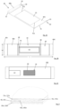
FIGURE 2A is an illustrative perspective view of the cover member and movement mechanism of the casing ofFigure 1 ; -
FIGURE 2B is an illustrative plan view of a first face of the cover member; -
FIGURE 2C is an illustrative plan view of a second face of the cover member; -
FIGURE 3 is a cross-sectional view of a part of a wall of a body of the casing and a part of the cover member ofFigure 1 ; -
FIGURE 4 is a cross sectional perspective view of the casing ofFigure 1 , with the cover member in a closed position; -
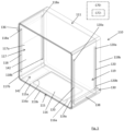
FIGURE 5 is a perspective view of a part of a printing assembly including an alternative casing with a cover member in a closed position; -
FIGURE 6 is a perspective view of the cover member ofFigure 5 ; -
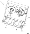
FIGURE 7 is a perspective view of a part of the casing ofFigure 1 orFigure 5 ; and -
FIGURE 8 is a perspective view of an alternative arrangement of a part of a casing. - Referring to
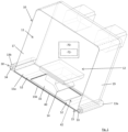
Figure 1 andFigure 4 , for example, there is shown a part of a printing assembly which includes acasing 10 which is configured to house at least a part of a printing apparatus 12 (only part of which is shown in the figures). Thecasing 10 includes abody 11 which may be moulded or formed by attaching a plurality of wall components together. Where wall components are attached together, additional sealing methods or components may be utilised to inhibit the ingress of liquids and/or solids between the wall components. A portion of thebody 11 may have a double-walled or double-skinned configuration, or thewhole body 11 may be double-walled. - The
body 11 includes aprinting opening 16. Theopening 16 may be provided in afirst wall 15 of thebody 11. Thefirst wall 15 may be double-walled, having aninner wall 15a and anouter wall 15b. Theopening 16 may be provided in theinner wall 15a and theouter wall 15b. The perimeter of theopening 16 may have smoothededges 16a, as shown inFigure 3 , for example. Theedges 16a of theopening 16 may be radiused. Theedges 16a of theopening 16 may be chamfered. Theedges 16a of theopening 16 may be chamfered and radiused. Thebody 11 may also includeside walls side walls first wall 15. -
Figures 1 and4 are cutaway views of the part of the printing assembly. It will be understood that thebody 11 may be a closed body with the exception of theprinting opening 16. Thebody 11 may be closed by engagement with a part of theprinting apparatus 12 or another device. For example, theprinting apparatus 12 may include a cassette upon which are mounted reels of inked ribbon, and thebody 11 may be configured to engage with a part of the cassette so as to close thebody 11. Theprinting opening 16 may be the only means of ingress into thebody 11 when thecasing 10 is in use, thebody 11 being otherwise sealed. A sealing formation, for example a gasket, may surround at least a part of perimeter of theprinting opening 16. - The
printing apparatus 12 may include aprinthead 14. Theprinthead 14 may be moveable relative to thecasing 10 between a printing position and a housed position. Theprinthead 14 may also be moveable to a cleaning position. The cleaning position may be a housed position. Theprinthead 14 may be moveable relative to thecasing 10 such that in a printing position at least a part of theprinthead 14 extends through theprinting opening 16, to enable theprinting apparatus 12 to carry out a printing operation on a substrate located approximately adjacent but external to thecasing 10. In the housed position, theprinthead 14 may be positioned inside thecasing 10. It will be understood that the whole of theprinthead 14 may be positioned inside thecasing 10 when theprinthead 14 is in the housed position. It will be understood that other positions of theprinthead 14 relative to thecasing 10 are possible. Theprinthead 14 may move between the printing position and a non-printing position while in use, for example. It may not be necessary or desirable for theprinthead 14 to retract into thecasing 10 during every non-printing operation. Such printing apparatuses typically operate at very high speeds, and it is advantageous to minimise the amount of movement of the printhead between printing operations, so as to enable printing speeds to be optimised. - The
casing 10 may be configured to house additional components of theprinting apparatus 12, for example rotatable spools for carrying reels of inked ribbon and/or motors and/or other moveable and/or electronic components (not shown). - The
casing 10 includes acover member 40. Features of thecover member 40 are shown in detail inFigures 2A-2C , for example. Thecover member 40 has afirst face 40a, and asecond face 40b. The cover member has a width W and a length L, measured between afirst end 40c of thecover member 40 and asecond end 40d of thecover member 40. Thefirst face 40a may be an inner face of thecover member 40, at least a part of which, in use, is directed towards the inside of thebody 11. Thesecond face 40b, may be an outer face of thecover member 40, at least a part of which, in use, may be directed to face outwardly relative to thebody 11. Thecover member 40 may include a plurality of layers. Thecover member 40 may include a flexible sheet of material. Thecover member 40 may include a water-resistant or waterproof portion. The whole of thecover member 40 may be water-resistant or waterproof. Thecover member 40 may be manufactured from or include a portion that is formed from a polymer. Thecover member 40 may be manufactured from or include a portion that is formed from closed cell foam. Thecover member 40 or a portion thereof may be compressible. Thecover member 40 may be integral with the casing. - The
cover member 40 includes anaperture 42. Theaperture 42 of thecover member 40 may be configured to be a similar size and or shape to theprinting opening 16 of thebody 11. Theedges 42a of the perimeter of theaperture 42 may be smoothed, for example chamfered and/or rounded, for example as shown inFigure 3 . - The
cover member 40 may include a sealingarrangement 44. The sealingarrangement 44 may include one or more of a sealingmember 45 and aplug member 46. The sealingmember 45 may be in the form of a gasket or thickened portion of thecover member 40 which at least partially surrounds the perimeter of theaperture 42. The sealingmember 45 may be attached to eitherface cover member 40, or may, for example, be sandwiched between layers of thecover member 40. - The
plug member 46 may include a portion of material which may be configured to be a similar shape and/or or size to theprinting opening 16. Theplug member 46 may be spaced from theaperture 42, or may be positioned adjacent theaperture 42. Theplug member 46 may be a thickened portion of thecover member 40. Theplug member 46 may be provided on the first orsecond face cover member 40, or may be provided as an intermediate layer between the first andsecond faces cover member 40. - The
cover member 40 may include one ormore reinforcement members 48 to strengthen thecover member 40. The or eachreinforcement member 48 may be provided in the region of theaperture 42. The or eachreinforcement member 48 may be in the form of a strip of stiffening material extending lengthwise or widthways along thecover member 40 on each side of theaperture 42. Theaperture 42 may be surrounded byreinforcement members 48. - The
cover member 40 may be attached to thebody 11 or otherwise mounted for movement relative to thebody 11. Thecover member 40 may be sandwiched between theinner wall 15a and theouter wall 15b of thefirst wall 15. - The
cover member 40 is moveable between a first, closed position and a second, open position relative to thebody 11. In the first, closed position, a portion of thecover member 40 substantially covers theprinting opening 16 of thebody 11. It will be appreciated that more than one position of thecover member 40 relative to thebody 11 may provide a closed position. In the second, open position, at least a part of theaperture 42 is aligned with theprinting opening 16. - The
casing 10 may include amovement mechanism 30 for moving thecover member 40 relative to thebody 11. - The
movement mechanism 30 may include at least one roller. Themovement mechanism 30 may include a pair ofrollers 31, 32 (as shown inFigures 1 ,2A and4 , for example). Themovement mechanism 30 may include an operating member. The operating member may include one or morerotatable knobs rotatable knob roller roller movement mechanism 30 may be controlled by acontrol device 72 which may be operable to control themovement mechanism 30 automatically (for example following a timed or programmed routine), or in response to an input or signal, which may be an operator input and/or a feedback signal. The control device may control themovement mechanisms 30 of a plurality ofcasings 10. Thecontrol device 72 is shown in dashed lines since its position is not significant. It may be positioned internally or externally of thecasing 10. - The or each
roller casing 10, for example inside thebody 11. Thebody 11 may include a pair ofroller housings rollers cover member 40. - The
first end 40c and thesecond end 40d of thecover member 40 may be attached to a respective one of therollers rollers cover member 40 on to and off therollers cover member 40 between therollers - In use, the
body 11 of thecasing 10 is positioned around the at least a part of theprinting apparatus 12 to provide a printing assembly. A part of the printing apparatus 12 (e.g., a cassette plate) may be positioned adjacent thebody 11, to substantially close thecasing 10. Thecover member 40 may be manually or automatically positioned in a default position. The default position of thecover member 40 may be the open position or the closed position. In the open position, theaperture 42 of thecover member 40 is at least partially aligned with theprinting opening 16, such that a part of the printing apparatus 12 (i.e., at least a part of the printhead 14) may extend at least partially through theprinting opening 16 and theaperture 42 of thecover member 40. In the open position of thecover member 40, theprinting apparatus 12 may carry out a printing operation on to a substrate which may be located externally of thecasing 10. - The
control device 72 may control movement and/or printing operations of theprinthead 14. - When the
cover member 40 is in the open position, the portion of thecover member 40 adjacent theaperture 42 may surround theprinting opening 16 of thebody 11, and seal against thebody 11, so as to inhibit the ingress of dust and/or liquids between thecover member 40 and thebody 11. The material of thecover member 40 may be compressed between the inner andouter walls body 11 to seal around theaperture 42. - When the
cover member 40 is to be moved to the closed position, therollers cover member 40 relative to thebody 11. The direction of rotation of eachroller end cover member 40 is attached to its correspondingroller end cover member 40 is windable on to and off itsrespective roller rollers rollers cover member 40 in the desired direction, thus winding thecover member 40 on to thatroller cover member 40 off theother roller - Where provided, the smoothed (e.g. chamfered/radiused) edges 16a of the
printing opening 16, and/or the smoothed (e.g. chamfered) edges 42a of theaperture 42 of thecover member 40 protect against thecover member 40 catching, snagging or becoming ruckled as thecover member 40 moves relative to thebody 11. For example, a smooth edge of theaperture 42 is able to slide over a smooth edge of theprinting opening 16 more easily than a flat or blunt edge of theaperture 42 will slide over a flat or blunt edge of theprinting opening 16. Where thefirst wall 15 is double walled, it will be understood that theedges 42a of theaperture 42 which extend widthways, i.e. across the width W of thecover member 40 are required to slide between the inner andouter walls edges 42a of theaperture 42 move past theedges 16a of theprinting opening 16. Smoothing one or both of theedges 16a of theprinting opening 16 and theedges 42a of theaperture 42 has the effect of guiding eachedge 42a of theaperture 42 between the inner andouter walls cover member 40. - The or each
roller respective knob cover member 40 may be moved in response to a signal, for example an electrical signal provided by acontrol device 72, and/or a feedback signal. Thecontrol device 72 may operate one or more motors to rotate one or bothrollers cover member 40 relative to thebody 11 between the first and second positions. - It will be understood that for the purposes of ingress protection, it is desirable for the
printing apparatus 12 to be positioned inside thebody 11 when thecover member 40 is moved towards the closed position, at least, to avoid obstructing or damaging thecover member 40. However, there may be circumstances in which it is desirable to move the printing apparatus towards a printing position when thecover member 40 is in the closed position, for example for the purpose of cleaning theprinthead 14, as will be explained below. - When the
cover member 40 is in the closed position relative to thebody 11, thecover member 40 covers or substantially covers theprinting opening 16 of thebody 11, such that thecasing 10 is sealed. - In the closed position, the
second face 40b of thecover member 40 is positioned sufficiently closely to thebody 11, for example thecover member 40 is sandwiched sufficiently tightly between theinner wall 15a and theouter wall 15b of thefirst wall 15 that theprinting opening 16 is adequately sealed by thecover member 40, so as to meet the desired ingress protection (IP) rating. Where at least a part (for example a layer) of thecover member 40 is manufactured from a compressible material, for example closed cell foam, thecover member 40 is compressed against thebody 11, for example the perimeter of theprinting opening 16, so as to provide an adequate seal. It will be understood that the seal may be broken by operation of themovement mechanism 30. In other words, the seal is a temporary seal. - In the closed position, where provided, the
plug member 46 may be substantially aligned with theprinting opening 16. Theplug member 46 may engage with theprinting opening 16 so as to enhance the seal between thecover member 40 and thebody 11, so as to protect against the ingress of solids and/or liquids into thecasing 10 when thecover member 40 is in the closed position. - To move the
cover member 40 to the open position relative to thebody 11, themovement mechanism 30 may be operated in reverse compared with the movement to move thecover member 40 to the closed position. For example, if therollers cover member 40 from the open position to the closed position, anticlockwise rotation of therollers cover member 40 from the closed position to the open position. It will be understood that further rotation of therollers cover member 40 to the open position may enable thecover member 40 to be moved to an alternative closed position. - An
alternative casing 110 is shown inFigure 5 , for example. Thecasing 110 is configured to house at least a part of aprinting apparatus 12. The features of theprinting apparatus 12 may be identical to those described above. - The
casing 110 includes abody 111 which may be moulded or formed by attaching a plurality of wall components together. Where wall components are attached together, additional sealing methods or components may be utilised to inhibit the ingress of liquids and/or solids between the wall components. Thebody 111 may be double-walled or may include a double walled portion. Thebody 111 includes afirst wall 115. Thebody 111 may include afirst side wall 117 and asecond side wall 119. - The
body 111 includes aprinting opening 116. Theprinting opening 116 may be provided in thefirst wall 115. The perimeter of theopening 116 may have smoothededges 116a. Theedges 116a of theopening 116 may be radiused. The edges of theopening 116a may be chamfered. Theedges 116a of theopening 116 may be chamfered and radiused for the reasons outlined above. - The
first wall 115 may be double-walled, having aninner wall 115a and anouter wall 115b. Thefirst side wall 117 and/or thesecond side wall 119 may be double-walled, having respectiveinner walls outer walls body 111 may be a closed body with the exception of theprinting opening 116. Thebody 111 may be closed by engagement with a part of theprinting apparatus 12 or another device. For example, theprinting apparatus 12 may include a cassette upon which are mounted reels of inked ribbon, and thebody 111 may be configured to engage with a part of the cassette so as to close thebody 111. Theprinting opening 116 may be the only means of liquid and/or particle ingress into thebody 111 when thecasing 110 is in use, thebody 111 being otherwise sealed. - As explained above, the
printhead 14 may be moveable relative to thecasing 110 between a printing position and a housed position in which theprinthead 14 is positioned inside thebody 111. Theprinthead 14 may also be movable to a cleaning position. The cleaning position may be a housed position. Thecasing 110 may be configured to house additional components of theprinting apparatus 12, for example rotatable spools for carrying reels of inked ribbon and/or motors and/or other moveable and/or electronic components (not shown). - The
casing 110 includes acover member 140. Thecover member 140 has afirst face 140a, and asecond face 140b. Thecover member 140 may be formed as a substantially continuous loop, for example as shown inFigure 6 . Thecover member 140 may have a width W. Thefirst face 140a may be an inner face of thecover member 140, at least a part of which, in use, may be directed towards the inside of thebody 111. Thesecond face 140b, may be an outer face of thecover member 140, at least a part of which, in use, may be directed to face outwardly relative to thebody 111. Thecover member 140 may include a plurality of layers. Thecover member 140 may include a flexible sheet of material. Thecover member 140 may include a water-resistant or waterproof portion. The whole of thecover member 140 may be water-resistant or waterproof. Thecover member 140 may be manufactured from or include a portion that is formed from a polymer. Thecover member 140 may be manufactured from or include a portion that is formed from closed cell foam. Thecover member 140 or a portion thereof may be compressible. - The
cover member 140 includes anaperture 142. Theaperture 142 of thecover member 140 may be configured to be a similar size and or shape to theprinting opening 116 of thebody 111. Theedges 142a of the perimeter of theaperture 142 may be smoothed, for example chamfered, for the reasons explained above. - The
cover member 140 may include a sealing arrangement similar to that of thecover member 40. The sealing arrangement may include one or more of a sealing member and a plug member as described above. - The
cover member 140 may include one ormore reinforcement members 148 to strengthen thecover member 140. The or eachreinforcement member 148 may be provided in the region of theaperture 142.Reinforcement members 148 may surround theaperture 142. The or eachreinforcement member 148 may be similar in any or all respects to the or eachreinforcement member 48 described above. - The
cover member 140 may be mounted for movement relative to thebody 111. Thecover member 140 may be sandwiched between theinner walls outer walls - The
cover member 140 is moveable between a first, closed position and a second, open position. Thecover member 140 may be moveable in a substantially clockwise or anticlockwise direction relative to thebody 111. In the first, closed position, a portion of thecover member 140 substantially covers theprinting opening 116 of thebody 111. In the second, open position, at least a part of theaperture 142 of thecover member 140 is aligned with theprinting opening 116. - The
casing 110 may include amovement mechanism 130 for moving thecover member 140 relative to thebody 11. - The
movement mechanism 130 may include an operating member. The operating member may include anengagement member 136. Themovement mechanism 130 may include asecond engagement member 138. The or eachengagement member engagement member engagement member cover member 140. The or eachengagement member cover member 140, however, it will be appreciated that this is not essential. - The size and/or shape of the or each
engagement member cover member 140, for example to reduce the likelihood of deformation and/or tearing of thecover member 140 as a result of torsion and/or shear forces being applied to thecover member 140 when thecover member 140 is moved relative to thebody 111. - The
movement mechanism 130 may include anopening 118 in thefirst side wall 117 of the body 111 (seeFigure 5 ). Where the body 111 (in particular the side wall 117) is double walled, theopening 118 may be provided only in theouter wall 117b of thefirst side wall 117. Theopening 118 may have afirst end 118a and asecond end 118b. Theopening 118 may be a slot. Theopening 118 may be a pair of slots, each having afirst end 118a and asecond end 118b. Thefirst engagement member 138 may include a portion which extends through theopening 118. Themovement mechanism 130 may include asecond opening 120 in the second side wall of thebody 111. Where the body 111 (in particular the side wall 119) is double walled, thesecond opening 120 may be provided only in theouter wall 119b of thesecond side wall 119. Thesecond opening 120 may have afirst end 120a and asecond end 120b. Thesecond opening 120 may be a slot. Thesecond opening 120 may be a pair of slots, each having afirst end 120a and asecond end 120b. Thesecond engagement member 138 may include a portion which extends through thesecond opening 120. The or each of the first andsecond engagement member respective opening opening cover member 140 relative to thebody 111 to move thecover member 140 between its closed position and its open position. The or eachopening cover member 140 covers the or eachopening cover member 140 is in a closed position relative to thebody 111. The or eachopening cover member 140 always covers the or eachopening cover member 140 is in an open position or a closed position. - In use, the
body 111 of thecasing 110 is positioned around the at least a part of theprinting apparatus 12 to form a printing assembly. A part of the printing apparatus 12 (e.g., a cassette plate) may be positioned adjacent thebody 111, to substantially close thecasing 110. Thecover member 140 may be manually or automatically positioned in a default position. The default position may be the open position or the closed position. In the open position, theaperture 142 of thecover member 140 is at least partially aligned with theprinting opening 116, such that a part of the printing apparatus 12 (i.e., a part of the printhead14) is able to extend at least partially through theprinting opening 116 and theaperture 142. In the open position of thecover member 140, theprinting apparatus 12 is able to carry out a printing operation on to a substrate which may be located externally of thecasing 110. - When the
cover member 140 is in the open position the sealing member (where provided) may be positioned around theprinting opening 16 of thebody 111, so as to protect against the ingress of particles, e.g., dust, and/or liquids between thecover member 140 and thebody 111. - When the
cover member 140 is to be moved between the open position and the closed position, one or both of theengagement members cover member 140 relative to thebody 111. -
Figure 5 shows thecover member 140 in a closed position. When thecover member 140 is in the closed position, thecover member 140 covers or substantially covers theprinting opening 116 of thebody 111, such that thecasing 110 is sealed. A part of theaperture 142 is adjacent thefirst side wall 117, in the example shown. It will be appreciated that there may be more than one position of thecover member 140 relative to thebody 111 which provides a closed position. Theaperture 142 of thecover member 140 may be positioned such that no part of theaperture 142 is aligned with theprinting opening 116 in the closed position. Thecover member 140 substantially covers and seals theprinting opening 116. - It will be understood that at least the
second face 140b of thecover member 140 is positioned sufficiently closely to thebody 111, for example where thebody 111 is double-walled, thecover member 140 may be sandwiched sufficiently tightly between theinner wall 115a and theouter wall 115b of the first wall 115 (and preferably theinner walls outer walls second side walls 117, 119) that theprinting opening 116 is adequately sealed by thecover member 140, so as to meet the desired ingress protection (IP) rating. Where at least a part (for example a layer) of thecover member 140 is manufactured from a compressible material, for example closed cell foam, thecover member 140 is compressed against thebody 111, for example around the perimeter of theprinting opening 116, so as to provide an adequate seal. It will be understood that the seal between thecover member 140 and thebody 111 may be broken by operation of themovement mechanism 130. In other words, the seal is a temporary seal. - Where provided, the plug member may be substantially aligned with the
printing opening 116 in the closed position. The plug member may engage with theprinting opening 116 so as to enhance a seal between thecover member 140 and thebody 111, so as to protect against the ingress of solids and/or liquids into thecasing 110 when thecover member 140 is in the closed position. - In the example shown in
Figure 5 , thecover member 140 is in a closed position in which thefirst engagement member 136 is positioned at towards thefirst end 118a of thefirst opening 118 and thesecond engagement member 138 is positioned towards thesecond end 120b of thesecond opening 120. To move thecover member 140 to an open position relative to thebody 111, one or both of theengagement members other end respective opening cover member 140 may reach the open position before eachengagement member other end respective opening engagement members other engagement member respective opening cover member 140. It will be understood that this is one of at least two alternative methods of moving thecover member 140 from its closed position to its open position; and is explained as an example only. - The
cover member 140 may be moved relative to thebody 111 in response to a signal. Movement of thecover member 140 may be controlled manually, mechanically or electrically, for example. The or eachmovement mechanism 130 may be operable manually, mechanically or electrically, for example. The or eachengagement member respective opening control device 172 may provide a signal to control the movement of thecover member 140 relative to thebody 111. The control of movement of thecover member 140 may be in response to a programmed or timed routine, or may be in response to an input, for example a user input. Thecontrol device 172 is shown in dashed lines since its position is not significant. It may be positioned internally or externally of thecasing 110. - The
control device cover member respective body control system control system printing apparatus 12, by operation of a printing apparatus control device. Thecontrol device - The
control device casings respective movement mechanism casing casings - The
control system cover member body control system cover member body cover member cover member body cover member body body inner walls more monitoring apertures 52, 152 to facilitate the monitoring of position and/or movement of thecover member body body more monitoring apertures 52, 152, enables direct sensing of the sensed element 50, 150 by a sensor positioned adjacent themonitoring aperture 52, 152. The or each sensor may be positioned inside or outside thebody - Additionally or alternatively, the or each motor responsible for the movement of the
cover member body - The
cover member more cleaning portions portion inner face cover member portion portion printhead 14 may be brought into contact with the cleaningportion cleaning portions portion cover member portion cleaning portions printhead 14 when thecover member body - To carry out a cleaning operation, the
cover member body printhead 14 and the cleaningportion printhead 14 and thecover member cleaning portion cover member printing apparatus 12. Thecover member printhead 14 bearing against it during the printhead cleaning operation. Thecover member control system cover member printhead 14. The cleaning operation may include one or more of the following steps: moving the cover member 40,140 to a closed position relative to thebody portion printhead 14, moving theprinthead 14 and thecover member cover member printhead 14; moving thecover member body cover member body - As described and shown herein, the
cover member cover member body cover member body aperture cover member side walls cover member aperture cover member opening Figure 8 ), but does not substantially move relative to theside walls cover member cover member movement mechanism 230 may be provided which is similar to one of themovement mechanisms Figure 8 shows a pair ofrollers rollers body 11, compared with the orientation of therollers cover member 40 ofFigure 8 is moveable by rotating one or both of therollers - The casing as disclosed herein provides ingress protection which does not require separate bags or covers. The cover member provides integrated ingress protection, which, being integrated with the printing assembly, is always available, and is quick and simple to operate. The printing apparatus or parts thereof do not have to be removed from the printing assembly during cleaning of the production line to protect the printing apparatus from the ingress of liquids and or solids.
- The addition of the cleaning portion enables a printhead cleaning operation to be carried out simultaneously with a cleaning process for the production line in which the printing assembly is installed. This saves time and labour.
- When used in this specification and claims, the terms "seal" or "sealed" will be understood to mean that the
casing
Claims (15)
- A casing (10, 110) for a printing apparatus (12), the casing (10, 110) includinga body (11, 111) having a printing opening (16, 116), anda cover member (40, 140) having an aperture (42, 142),characterised in thatthe cover member (40, 140) is moveable relative to the body (11, 111) between an open position in which at least a part of the aperture (42, 142) of the cover member (40, 140) is substantially aligned with the printing opening (16, 116) of the body (11, 111), and a closed position in which at least a part of the cover member (40, 140) substantially closes the printing opening (16, 116) of the body (11, 111).
- A casing (10, 110) according to claim 1 including a movement mechanism (30, 130) for moving the cover member (40, 140) relative to the body (11, 111).
- A casing (10, 110) according to claim 2 wherein the movement mechanism (30, 230) includes at least one roller (31, 32, 231, 232) around which a part of the cover member (40, 140) is able to be wound.
- A casing (110) according to claim 2 wherein the movement mechanism (130) includes at least one engagement member (136, 138) provided on the cover member (140) and at least one respective opening (118, 120) in the body (111), wherein a part of the or each engagement member (136, 138) extends through its respective opening (118, 120).
- A casing (10, 110) according to any of the preceding claims wherein movement of the cover member (40, 140) relative to the body (11, 111) is controlled manually and/or mechanically and/or electrically.
- A casing (10, 110) according to any of the preceding claims wherein when the cover member (40, 140) is in the closed position relative to the body (11, 111), the cover member (40, 140) provides protection against the ingress of solids and/or liquids into the casing (10, 110).
- A casing (10, 110) according to any one of the preceding claims wherein the cover member (40, 140) includes a cleaning portion (60, 160) for cleaning a printhead (14).
- A printing assembly including a printhead (14) and a casing (10, 110) according to any one of claims 1 to 7 for housing the printhead (14).
- A control system (70, 170) for a printing assembly according to claim 8, wherein the control system (70, 170) includes a control device which is operable to control the movement of the cover member (40, 140) relative to the body (11, 111).
- A control system (70, 170) according to claim 9 wherein the control device is operable to control a plurality of printing assemblies.
- An operation method of a printing assembly of claim 8, wherein the method includes controlling the movement of the cover member (40, 140) relative to the body (11, 111) of the casing (10, 110), between the open position and the closed position.
- An operation method according to claim 11 wherein the method further includes controlling movement of the printhead (14) between a printing position and a non-printing position.
- An operation method according to claim 11 or claim 12 wherein the method includes a printhead cleaning operation.
- An operation method according to claim 13 wherein the printhead cleaning operation includes at least one of the following steps:moving the cover member (40, 140) to a closed position relative to the body (11, 111);positioning the cleaning portion (60, 160) adjacent or near the printhead (14);moving the printhead (14) and the cover member (40, 140) relative to one another, by movement of one or both of the cover member (40, 140) and the printhead (14);moving the cover member (40, 140) relative to the body (11, 111) to move the cover member (40, 140) to an open position relative to the body (11, 111).
- An operation method according to any of claims 11 to 14 including controlling the operation of a plurality of printing assemblies according to claim 8.
Applications Claiming Priority (1)
| Application Number | Priority Date | Filing Date | Title |
|---|---|---|---|
| GB2206604.7A GB2618375A (en) | 2022-05-05 | 2022-05-05 | Printing apparatus and method of operation |
Publications (2)
| Publication Number | Publication Date |
|---|---|
| EP4272970A1 EP4272970A1 (en) | 2023-11-08 |
| EP4272970B1 true EP4272970B1 (en) | 2025-07-02 |
Family
ID=86330130
Family Applications (1)
| Application Number | Title | Priority Date | Filing Date |
|---|---|---|---|
| EP23171742.2A Active EP4272970B1 (en) | 2022-05-05 | 2023-05-04 | Printing apparatus and method of operation |
Country Status (4)
| Country | Link |
|---|---|
| US (1) | US12479225B2 (en) |
| EP (1) | EP4272970B1 (en) |
| CN (1) | CN117002158A (en) |
| GB (1) | GB2618375A (en) |
Family Cites Families (5)
| Publication number | Priority date | Publication date | Assignee | Title |
|---|---|---|---|---|
| JPS5590391A (en) * | 1978-12-28 | 1980-07-08 | Seiko Epson Corp | Thermal printer |
| US6742864B2 (en) * | 2002-04-30 | 2004-06-01 | Hewlett-Packard Development Company, L.P. | Waste ink removal system |
| JP2004034411A (en) * | 2002-07-01 | 2004-02-05 | Sankyo Seiki Mfg Co Ltd | Cassette for hot stamp foil tape |
| GB2507876B (en) * | 2012-09-12 | 2014-10-08 | Linx Printing Tech | Ink jet print head and cap |
| CN212889518U (en) * | 2020-07-28 | 2021-04-06 | 重庆金云合科技有限公司 | Dustproof device for inkjet printer |
-
2022
- 2022-05-05 GB GB2206604.7A patent/GB2618375A/en active Pending
-
2023
- 2023-05-04 EP EP23171742.2A patent/EP4272970B1/en active Active
- 2023-05-05 CN CN202310494798.9A patent/CN117002158A/en active Pending
- 2023-05-05 US US18/313,095 patent/US12479225B2/en active Active
Also Published As
| Publication number | Publication date |
|---|---|
| CN117002158A (en) | 2023-11-07 |
| EP4272970A1 (en) | 2023-11-08 |
| US12479225B2 (en) | 2025-11-25 |
| US20230356538A1 (en) | 2023-11-09 |
| GB2618375A (en) | 2023-11-08 |
Similar Documents
| Publication | Publication Date | Title |
|---|---|---|
| TWI686313B (en) | Tape cartridge | |
| CN107878049B (en) | Tape box | |
| CN106103113B (en) | with box | |
| TWI710476B (en) | With cassette | |
| CN100532110C (en) | Tape printer | |
| CN106132712B (en) | Tape printing apparatus and with print system | |
| KR101892485B1 (en) | Tape cartridge | |
| EP4272970B1 (en) | Printing apparatus and method of operation | |
| EP3524437B1 (en) | Printer | |
| CN100591528C (en) | thermal transfer printer cover | |
| JP3787407B2 (en) | Paper supply cartridge | |
| EP3124259B1 (en) | Tape printing device | |
| JP7608228B2 (en) | Label printer | |
| JP3549370B2 (en) | Cartridge and recording device using this cartridge | |
| JP2003341889A (en) | Paper feed magazine for recording paper roll | |
| JP6116309B2 (en) | Printer | |
| JP7275970B2 (en) | Waste liquid recovery device, liquid discharge device | |
| JP3552576B2 (en) | Band-shaped housing structure | |
| JP7723509B2 (en) | label printer | |
| JP4576275B2 (en) | Ribbon cassette device | |
| KR950015005A (en) | Electrostatic latent image developing apparatus and toner car atridge applied thereto | |
| JP2006151561A (en) | Recording medium cassette, integrated cassette, printing apparatus and printed material processing apparatus | |
| JP2004358790A (en) | Printer with drive mechanism using worm gear | |
| JPH11277812A (en) | Portable printer | |
| JP4705419B2 (en) | Cover lock mechanism |
Legal Events
| Date | Code | Title | Description |
|---|---|---|---|
| PUAI | Public reference made under article 153(3) epc to a published international application that has entered the european phase |
Free format text: ORIGINAL CODE: 0009012 |
|
| STAA | Information on the status of an ep patent application or granted ep patent |
Free format text: STATUS: THE APPLICATION HAS BEEN PUBLISHED |
|
| AK | Designated contracting states |
Kind code of ref document: A1 Designated state(s): AL AT BE BG CH CY CZ DE DK EE ES FI FR GB GR HR HU IE IS IT LI LT LU LV MC ME MK MT NL NO PL PT RO RS SE SI SK SM TR |
|
| STAA | Information on the status of an ep patent application or granted ep patent |
Free format text: STATUS: REQUEST FOR EXAMINATION WAS MADE |
|
| 17P | Request for examination filed |
Effective date: 20240503 |
|
| RBV | Designated contracting states (corrected) |
Designated state(s): AL AT BE BG CH CY CZ DE DK EE ES FI FR GB GR HR HU IE IS IT LI LT LU LV MC ME MK MT NL NO PL PT RO RS SE SI SK SM TR |
|
| GRAP | Despatch of communication of intention to grant a patent |
Free format text: ORIGINAL CODE: EPIDOSNIGR1 |
|
| STAA | Information on the status of an ep patent application or granted ep patent |
Free format text: STATUS: GRANT OF PATENT IS INTENDED |
|
| INTG | Intention to grant announced |
Effective date: 20241127 |
|
| GRAS | Grant fee paid |
Free format text: ORIGINAL CODE: EPIDOSNIGR3 |
|
| GRAA | (expected) grant |
Free format text: ORIGINAL CODE: 0009210 |
|
| STAA | Information on the status of an ep patent application or granted ep patent |
Free format text: STATUS: THE PATENT HAS BEEN GRANTED |
|
| AK | Designated contracting states |
Kind code of ref document: B1 Designated state(s): AL AT BE BG CH CY CZ DE DK EE ES FI FR GB GR HR HU IE IS IT LI LT LU LV MC ME MK MT NL NO PL PT RO RS SE SI SK SM TR |
|
| REG | Reference to a national code |
Ref country code: GB Ref legal event code: FG4D |
|
| REG | Reference to a national code |
Ref country code: CH Ref legal event code: EP |
|
| REG | Reference to a national code |
Ref country code: DE Ref legal event code: R096 Ref document number: 602023004414 Country of ref document: DE |
|
| REG | Reference to a national code |
Ref country code: IE Ref legal event code: FG4D |
|
| P01 | Opt-out of the competence of the unified patent court (upc) registered |
Free format text: CASE NUMBER: APP_32102/2025 Effective date: 20250702 |
|
| REG | Reference to a national code |
Ref country code: NL Ref legal event code: MP Effective date: 20250702 |
|
| PG25 | Lapsed in a contracting state [announced via postgrant information from national office to epo] |
Ref country code: PT Free format text: LAPSE BECAUSE OF FAILURE TO SUBMIT A TRANSLATION OF THE DESCRIPTION OR TO PAY THE FEE WITHIN THE PRESCRIBED TIME-LIMIT Effective date: 20251103 |
|
| PG25 | Lapsed in a contracting state [announced via postgrant information from national office to epo] |
Ref country code: NL Free format text: LAPSE BECAUSE OF FAILURE TO SUBMIT A TRANSLATION OF THE DESCRIPTION OR TO PAY THE FEE WITHIN THE PRESCRIBED TIME-LIMIT Effective date: 20250702 |
|
| REG | Reference to a national code |
Ref country code: AT Ref legal event code: MK05 Ref document number: 1808821 Country of ref document: AT Kind code of ref document: T Effective date: 20250702 |
|
| PG25 | Lapsed in a contracting state [announced via postgrant information from national office to epo] |
Ref country code: IS Free format text: LAPSE BECAUSE OF FAILURE TO SUBMIT A TRANSLATION OF THE DESCRIPTION OR TO PAY THE FEE WITHIN THE PRESCRIBED TIME-LIMIT Effective date: 20251102 |
|
| PG25 | Lapsed in a contracting state [announced via postgrant information from national office to epo] |
Ref country code: NO Free format text: LAPSE BECAUSE OF FAILURE TO SUBMIT A TRANSLATION OF THE DESCRIPTION OR TO PAY THE FEE WITHIN THE PRESCRIBED TIME-LIMIT Effective date: 20251002 |
|
| REG | Reference to a national code |
Ref country code: LT Ref legal event code: MG9D |
|
| PG25 | Lapsed in a contracting state [announced via postgrant information from national office to epo] |
Ref country code: AT Free format text: LAPSE BECAUSE OF FAILURE TO SUBMIT A TRANSLATION OF THE DESCRIPTION OR TO PAY THE FEE WITHIN THE PRESCRIBED TIME-LIMIT Effective date: 20250702 |
|
| PG25 | Lapsed in a contracting state [announced via postgrant information from national office to epo] |
Ref country code: FI Free format text: LAPSE BECAUSE OF FAILURE TO SUBMIT A TRANSLATION OF THE DESCRIPTION OR TO PAY THE FEE WITHIN THE PRESCRIBED TIME-LIMIT Effective date: 20250702 |
|
| PG25 | Lapsed in a contracting state [announced via postgrant information from national office to epo] |
Ref country code: HR Free format text: LAPSE BECAUSE OF FAILURE TO SUBMIT A TRANSLATION OF THE DESCRIPTION OR TO PAY THE FEE WITHIN THE PRESCRIBED TIME-LIMIT Effective date: 20250702 |
|
| PG25 | Lapsed in a contracting state [announced via postgrant information from national office to epo] |
Ref country code: GR Free format text: LAPSE BECAUSE OF FAILURE TO SUBMIT A TRANSLATION OF THE DESCRIPTION OR TO PAY THE FEE WITHIN THE PRESCRIBED TIME-LIMIT Effective date: 20251003 |
|
| PG25 | Lapsed in a contracting state [announced via postgrant information from national office to epo] |
Ref country code: CZ Free format text: LAPSE BECAUSE OF FAILURE TO SUBMIT A TRANSLATION OF THE DESCRIPTION OR TO PAY THE FEE WITHIN THE PRESCRIBED TIME-LIMIT Effective date: 20250702 Ref country code: SE Free format text: LAPSE BECAUSE OF FAILURE TO SUBMIT A TRANSLATION OF THE DESCRIPTION OR TO PAY THE FEE WITHIN THE PRESCRIBED TIME-LIMIT Effective date: 20250702 |
|
| PG25 | Lapsed in a contracting state [announced via postgrant information from national office to epo] |
Ref country code: LV Free format text: LAPSE BECAUSE OF FAILURE TO SUBMIT A TRANSLATION OF THE DESCRIPTION OR TO PAY THE FEE WITHIN THE PRESCRIBED TIME-LIMIT Effective date: 20250702 |
|
| PG25 | Lapsed in a contracting state [announced via postgrant information from national office to epo] |
Ref country code: BG Free format text: LAPSE BECAUSE OF FAILURE TO SUBMIT A TRANSLATION OF THE DESCRIPTION OR TO PAY THE FEE WITHIN THE PRESCRIBED TIME-LIMIT Effective date: 20250702 Ref country code: PL Free format text: LAPSE BECAUSE OF FAILURE TO SUBMIT A TRANSLATION OF THE DESCRIPTION OR TO PAY THE FEE WITHIN THE PRESCRIBED TIME-LIMIT Effective date: 20250702 |
|
| PG25 | Lapsed in a contracting state [announced via postgrant information from national office to epo] |
Ref country code: RS Free format text: LAPSE BECAUSE OF FAILURE TO SUBMIT A TRANSLATION OF THE DESCRIPTION OR TO PAY THE FEE WITHIN THE PRESCRIBED TIME-LIMIT Effective date: 20251002 |
|
| PG25 | Lapsed in a contracting state [announced via postgrant information from national office to epo] |
Ref country code: ES Free format text: LAPSE BECAUSE OF FAILURE TO SUBMIT A TRANSLATION OF THE DESCRIPTION OR TO PAY THE FEE WITHIN THE PRESCRIBED TIME-LIMIT Effective date: 20250702 |