EP4272899A2 - One-piece fill valve for powered fastener driver - Google Patents
One-piece fill valve for powered fastener driver Download PDFInfo
- Publication number
- EP4272899A2 EP4272899A2 EP23171144.1A EP23171144A EP4272899A2 EP 4272899 A2 EP4272899 A2 EP 4272899A2 EP 23171144 A EP23171144 A EP 23171144A EP 4272899 A2 EP4272899 A2 EP 4272899A2
- Authority
- EP
- European Patent Office
- Prior art keywords
- storage chamber
- fill valve
- fill
- cylinder
- compressed gas
- Prior art date
- Legal status (The legal status is an assumption and is not a legal conclusion. Google has not performed a legal analysis and makes no representation as to the accuracy of the status listed.)
- Granted
Links
Images







Classifications
-
- F—MECHANICAL ENGINEERING; LIGHTING; HEATING; WEAPONS; BLASTING
- F16—ENGINEERING ELEMENTS AND UNITS; GENERAL MEASURES FOR PRODUCING AND MAINTAINING EFFECTIVE FUNCTIONING OF MACHINES OR INSTALLATIONS; THERMAL INSULATION IN GENERAL
- F16K—VALVES; TAPS; COCKS; ACTUATING-FLOATS; DEVICES FOR VENTING OR AERATING
- F16K15/00—Check valves
- F16K15/18—Check valves with actuating mechanism; Combined check valves and actuated valves
- F16K15/182—Check valves with actuating mechanism; Combined check valves and actuated valves with actuating mechanism
- F16K15/1825—Check valves with actuating mechanism; Combined check valves and actuated valves with actuating mechanism for check valves with flexible valve members
-
- B—PERFORMING OPERATIONS; TRANSPORTING
- B25—HAND TOOLS; PORTABLE POWER-DRIVEN TOOLS; MANIPULATORS
- B25C—HAND-HELD NAILING OR STAPLING TOOLS; MANUALLY OPERATED PORTABLE STAPLING TOOLS
- B25C1/00—Hand-held nailing tools; Nail feeding devices
- B25C1/04—Hand-held nailing tools; Nail feeding devices operated by fluid pressure, e.g. by air pressure
- B25C1/041—Hand-held nailing tools; Nail feeding devices operated by fluid pressure, e.g. by air pressure with fixed main cylinder
- B25C1/042—Main valve and main cylinder
-
- B—PERFORMING OPERATIONS; TRANSPORTING
- B25—HAND TOOLS; PORTABLE POWER-DRIVEN TOOLS; MANIPULATORS
- B25C—HAND-HELD NAILING OR STAPLING TOOLS; MANUALLY OPERATED PORTABLE STAPLING TOOLS
- B25C1/00—Hand-held nailing tools; Nail feeding devices
- B25C1/04—Hand-held nailing tools; Nail feeding devices operated by fluid pressure, e.g. by air pressure
- B25C1/047—Mechanical details
-
- B—PERFORMING OPERATIONS; TRANSPORTING
- B25—HAND TOOLS; PORTABLE POWER-DRIVEN TOOLS; MANIPULATORS
- B25C—HAND-HELD NAILING OR STAPLING TOOLS; MANUALLY OPERATED PORTABLE STAPLING TOOLS
- B25C1/00—Hand-held nailing tools; Nail feeding devices
- B25C1/06—Hand-held nailing tools; Nail feeding devices operated by electric power
-
- F—MECHANICAL ENGINEERING; LIGHTING; HEATING; WEAPONS; BLASTING
- F16—ENGINEERING ELEMENTS AND UNITS; GENERAL MEASURES FOR PRODUCING AND MAINTAINING EFFECTIVE FUNCTIONING OF MACHINES OR INSTALLATIONS; THERMAL INSULATION IN GENERAL
- F16K—VALVES; TAPS; COCKS; ACTUATING-FLOATS; DEVICES FOR VENTING OR AERATING
- F16K15/00—Check valves
- F16K15/14—Check valves with flexible valve members
- F16K15/144—Check valves with flexible valve members the closure elements being fixed along all or a part of their periphery
- F16K15/147—Check valves with flexible valve members the closure elements being fixed along all or a part of their periphery the closure elements having specially formed slits or being of an elongated easily collapsible form
Definitions
- the present invention relates to powered fastener drivers, and more specifically to gas spring-powered fastener drivers.
- fastener drivers known in the art for driving fasteners (e.g., nails, tacks, staples, etc.) into a workpiece.
- fastener drivers operate utilizing various means known in the art (e.g. compressed air generated by an air compressor, electrical energy, a flywheel mechanism, etc.), but often these designs are met with power, size, and cost constraints.
- the present invention provides, in one aspect, a powered fastener driver.
- the powered fastener driver includes a piston cylinder, a piston, a driver blade, a lifter, a storage chamber cylinder, a fill port, and a one-piece fill valve.
- the piston is movable and is positioned within the piston cylinder.
- the driver blade is attached to the piston and movable therewith between a top-dead-center position and a bottom-dead-center position.
- the lifter is operable to move the driver blade from a driven position corresponding with the bottom-dead-center position toward a ready position.
- the storage chamber cylinder encloses the piston cylinder and defines therewith a storage chamber in which compressed gas is stored.
- the fill port is coupled to the storage chamber cylinder and is in communication with the storage chamber.
- the one-piece fill valve is at least partially positioned within the fill port.
- the fill valve includes a slit which, in a closed state, prevents gas in the storage chamber from being discharged to the atmosphere through the fill valve. In an open state of the slit, the slit permits the storage chamber to be refilled with compressed gas through the fill valve. A pressure exerted on a portion of the fill valve in which the slit is defined by compressed gas within the storage chamber maintains the slit in the closed state.
- the present invention provides, in another aspect, a powered fastener driver.
- the powered fastener driver includes a piston cylinder, a piston, a driver blade, a lifter, a storage chamber cylinder, a fill port, and a one-piece fill valve.
- the piston is movably positioned within the piston cylinder.
- the driver blade is attached to the piston and is movable therewith between a top-dead-center position and a bottom-dead-center position.
- the lifter is operable to move the driver blade from a driven position corresponding with the bottom-dead-center position toward a ready position.
- the storage chamber cylinder encloses the piston cylinder and defines therewith a storage chamber in which compressed gas is stored.
- the fill port is coupled to the storage chamber cylinder and is in communication with the storage chamber.
- the one-piece fill valve is at least partially positioned within the fill port.
- the fill valve includes a body portion defining a receptacle, a tip portion terminating at a tip end, and a slit extending from the receptacle of the body portion to the tip end of the tip portion.
- the slit is movable between a closed state in which compressed gas in the storage chamber in prevented from being discharged to the atmosphere through the fill valve, and an open state which permits the storage chamber to be refilled with compressed gas through the fill valve.
- a pressure exerted on the tip end of the fill valve by compressed gas within the storage chamber maintains the slit in the closed state.
- the tip portion is configured to be received in the storage chamber cylinder.
- the present invention provides, in another aspect, a powered fastener driver.
- the gas spring-powered fastener driver includes a piston cylinder, a piston, a driver blade, a lifter, a storage chamber cylinder, a fill port, a one-piece fill valve, and a plug.
- the piston is movably positioned within the piston cylinder.
- the drive blade is attached to the piston and is movable therewith between a top-dead-center position and a bottom-dead-center position.
- the lifter is operable to move the driver blade from a driven position corresponding with the bottom-dead-center position and toward a ready position.
- the storage chamber cylinder encloses the piston cylinder and defines therewith a storage chamber in which compressed gas is stored.
- the fill port is coupled to the storage chamber cylinder and is in communication with the storage chamber.
- the one-piece fill valve is at least partially positioned within the fill port.
- the fill valve includes a slit which, in a closed state, prevents compressed gas in the storage chamber from being discharged to atmosphere through the fill valve, and in an open state, permits the storage chamber to be refilled with compressed gas through the fill valve.
- the plug is configured to engage the fill port to inhibit access of the fill valve.
- the present invention provides, in another aspect, a powered fastener driver.
- the gas spring-powered fastener driver includes a piston cylinder, a piston, a driver blade, a lifter, a storage chamber cylinder, a fill port, a one-piece fill valve, and a plug.
- the piston is movably positioned within the piston cylinder.
- the drive blade is attached to the piston and is movable therewith between a top-dead-center position and a bottom-dead-center position.
- the lifter is operable to move the driver blade from a driven position corresponding with the bottom-dead-center position toward a ready position.
- the storage chamber cylinder encloses the piston cylinder and defines therewith a storage chamber in which compressed gas is stored.
- the fill port is coupled to the storage chamber cylinder and is in communication with the storage chamber.
- the one-piece fill valve having a slit in a tip thereof and an adjacent a receptacle, and is at least partially positioned within the fill port.
- the fill valve includes a slit, in a closed state, prevents compressed gas in the storage chamber from being discharged to atmosphere through the fill valve, and in an open state, permits the storage chamber to be refilled with compressed gas through the fill valve.
- the plug has a tip configured to engage the receptacle of the one-piece fill valve to inhibit access of the fill valve.
- the present invention provides, in another aspect, a powered fastener driver.
- the gas spring-powered fastener driver includes a piston cylinder, a piston, a driver blade, a lifter, a storage chamber cylinder, a fill port, a one-piece fill valve, an adapter, and a needle.
- the piston is movably positioned within the piston cylinder.
- the drive blade is attached to the piston and is movable therewith between a top-dead-center position and a bottom-dead-center position.
- the lifter is operable to move the driver blade from a driven position corresponding with the bottom-dead-center position toward a ready position.
- the storage chamber cylinder encloses the piston cylinder and defines therewith a storage chamber in which compressed gas is stored.
- the fill port is coupled to the storage chamber cylinder and is in communication with the storage chamber.
- the one-piece fill valve has a receptacle.
- the one-piece fill valve it at least partially positioned within the fill port.
- the fill valve includes a slit which, in a closed state, prevents compressed gas in the storage chamber from being discharged to atmosphere through the fill valve. In an open state of the slit, the storage chamber is permitted to be refilled with compressed gas through the fill valve.
- the adapter is coupled to the fill port adjacent the one-piece fill valve.
- the adapter has a cavity.
- the needle has a tip and a projection. The tip is configured to pass through the cavity and pierce the slit of the fill valve.
- the projection is configured to contact the receptacle of the fill valve to prevent compressed gas in the storage chamber from being discharged to atmosphere through the fill valve.
- the present invention provides, in another aspect, a powered fastener driver.
- the gas spring-powered fastener driver includes a piston cylinder, a piston, a driver blade, a lifter, a storage chamber cylinder, a fill port, and a one-piece fill valve.
- the piston is movable and is positioned within the piston cylinder.
- the driver blade is attached to the piston and movable therewith along a driving axis between a top-dead-center position and a bottom-dead-center position.
- the lifter is operable to move the driver blade from a driven position corresponding with the bottom-dead-center position toward a ready position.
- the storage chamber cylinder encloses the piston cylinder and defines therewith a storage chamber in which compressed gas is stored.
- the storage chamber cylinder has an annular inner wall surrounding the driving axis.
- the fill port is coupled to the storage chamber cylinder and is in communication with the storage chamber.
- the fill port extends along a filling axis tangent to the annular inner wall.
- the one-piece fill valve is at least partially positioned within the fill port.
- the fill valve includes a slit which, in a closed state, prevents gas in the storage chamber from being discharged to the atmosphere through the fill valve. In an open state of the slit, the slit permits the storage chamber to be refilled with compressed gas through the fill valve. A pressure exerted on a portion of the fill valve in which the slit is defined by compressed gas within the storage chamber maintains the slit in the closed state.
- the present invention provides, in another aspect, a powered fastener driver.
- the gas spring-powered fastener driver includes a piston cylinder, a piston, a driver blade, a lifter, a storage chamber cylinder, a fill port, and a one-piece fill valve.
- the piston is movable and is positioned within the piston cylinder.
- the driver blade is attached to the piston and movable therewith along a driving axis between a top-dead-center position and a bottom-dead-center position.
- the lifter is operable to move the driver blade from a driven position corresponding with the bottom-dead-center position toward a ready position.
- the storage chamber cylinder encloses the piston cylinder and defines therewith a storage chamber in which compressed gas is stored.
- the fill port is coupled to the storage chamber cylinder and is in communication with the storage chamber.
- the fill port extends along a filling axis that is obliquely oriented relative to the driving axis.
- the one-piece fill valve is at least partially positioned within the fill port.
- the fill valve includes a slit which, in a closed state, prevents gas in the storage chamber from being discharged to the atmosphere through the fill valve. In an open state of the slit, the slit permits the storage chamber to be refilled with compressed gas through the fill valve. A pressure exerted on a portion of the fill valve in which the slit is defined by compressed gas within the storage chamber maintains the slit in the closed state.
- the present disclosure provides, in another aspect, a powered fastener driver.
- the gas spring-powered fastener driver includes a piston cylinder, a piston, a drive blade, a lifter, a storage chamber cylinder, a fill port, a one-piece fill valve, and an intermediate block.
- the piston is movable and is positioned within the piston cylinder.
- the drive blade is attached to the piston and is movable therewith between a top-dead-center position and a bottom-dead-center position.
- the lifter is operable to move the driver blade from a driven position corresponding with the bottom-dead-center position toward a ready position.
- the storage chamber cylinder encloses the piston cylinder and defines therewith a storage chamber in which compressed gas is stored.
- the fill port is coupled to the storage chamber cylinder and is in communication with the storage chamber.
- the fill port includes a stepped inner surface.
- the one-piece fill valve has a head, a body, and a receptacle.
- the one-piece fill valve is at least partially positioned within the fill port, and includes a slot which, in a closed state, prevents compressed gas in the storage chamber from being discharged to atmosphere through the fill valve and, in an open state, permits the storage chamber to be refilled with compressed gas through the fill valve.
- the intermediate block is configured to be pressed into the fill port adjacent the one-piece valve.
- the intermediate block has a cylindrical body and an axial stop projecting radially inwardly from the cylindrical body. The axial stop of the intermediate block is configured to inhibit removal of the fill valve from the fill port.
- a powered fastener driver comprising:
- the fill valve may include a head portion, a body portion, and a tip portion, and wherein the head portion and the body portion may define a receptacle configured to receive a plug which further inhibits egress of air from the storage chamber cylinder.
- the receptacle may include a first portion, a second portion, and a transition portion between the first portion and the second portion, wherein the first portion and the second portion may be cylindrical in shape and have a first inner diameter and a second inner diameter, respectively, which are different from one another, and wherein the transition portion may be tapered between the first inner diameter and the second inner diameter.
- the head portion may be generally annularly shaped and includes a head outer diameter
- the body portion may be generally annularly shaped and includes a body outer diameter, and wherein the head outer diameter may be larger than the body outer diameter
- the fill valve may include a tip end and a receptacle with a counterbore surface, and wherein the slit of the fill valve may be in communication with the tip end and the counterbore surface.
- the counterbore surface may be substantially flat.
- the slit may have a length between the tip end and the receptacle between 1 millimeter and 5 millimeters.
- a powered fastener driver comprising:
- the fill port may include a conforming surface configured to receive the fill valve by an interference fit.
- the conforming surface may include a first annular portion having a first diameter and a second annular portion having a second diameter, wherein the first annular portion may be configured to receive at least the body portion of the fill valve, and wherein the second annular portion may be configured to receive at least the head portion of the fill valve.
- the fill port may further comprise an annular ring having a first axial surface, an annular surface, and a second axial surface, and wherein the first axial surface may be configured to provide a stop for a plug, and the second axial surface may be configured to provide a stop for the fill valve.
- An entirety of the slit may be positioned within the storage chamber cylinder.
- the receptacle may include a counterbore surface which may be positioned entirely within the storage chamber cylinder.
- a powered fastener driver comprising:
- the fill port may include a threaded portion
- the plug may include a body portion including threads, and wherein the threads of the body portion may be configured to engage the threaded portion of the fill port to secure the plug to the fill port.
- the threads of the body portion may be interrupted threads including flattened portions.
- the fill valve may include a receptacle, and the plug may further include a tip portion configured engage the receptacle to secure the fill valve to the fill port.
- the receptacle may include an inner diameter and the tip portion of the plug may include an outer diameter nominally greater than the inner diameter.
- the plug may include a head portion dimensioned with a size larger than the fill port to secure the plug with the fill port.
- the plug may be removable from the fill port to permit access to the fill valve.
- a powered fastener driver comprising:
- the fill port may include a threaded portion
- the plug may include a body portion including threads, and wherein the threads of the body portion may be configured to engage the threaded portion of the fill port to secure the plug to the fill port.
- the receptacle may include an inner diameter and the tip of the plug may include an outer diameter nominally greater than the inner diameter.
- the tip of the plug may have a variable outer diameter.
- the tip of the plug may have a linearly tapered outer diameter.
- the tip may be generally cylindrically shaped.
- a powered fastener driver comprising:
- the fill port may include a threaded portion and the adapter may include a body portion having threads, and wherein the threads of the body portion may be configured to engage the threaded portion of the fill port to secure the adapter to the fill port.
- the adapter may include a base and a body, wherein the cavity may include a base inner diameter adjacent the base and a tip inner diameter furthest away from the base, and wherein the tip inner diameter may be larger than the base inner diameter.
- the fill valve further includes a base, a body, and a tip, the receptacle of the fill valve including an inner diameter at least partially smaller than a diameter defined by the projection of the needle.
- the receptacle may include a tapered inner diameter.
- the inner diameter may be tapered to guide the needle into alignment with the slit.
- the adapter may include a through bore having a constant size.
- a powered fastener driver comprising:
- the filling axis may be tangent to the driving axis.
- the filling axis may be offset from the driving axis.
- the storage chamber cylinder may include an annular inner wall and the fastener driver may further include a stem chamber positioned between the inner wall and the fill valve.
- a tip of a needle may be configured to crack the fill valve and be positioned within the stem chamber, without entering the storage chamber cylinder.
- a powered fastener driver comprising:
- the filling axis may be angled relative to the driving axis at an angle between 0 degrees and 90 degrees.
- the filling axis may be angled relative to the driving axis at an angle between 15 degrees and 75 degrees.
- the filling axis may intersect the driving axis.
- the filling axis may be obliquely oriented relative to the driving axis but does not intersect the driving axis.
- the storage chamber cylinder may include an annular inner wall, and wherein the fastener driver may further include a stem chamber positioned between the inner wall and the fill valve.
- a tip of a needle may be configured to crack the fill valve and be positioned within the stem chamber without entering the storage chamber cylinder.
- a powered fastener driver comprising:
- the stepped inner surface of the fill port may include an outer portion, an inner portion, and an intermediate portion between the outer portion and the inner portion, and wherein the outer portion, inner portion, and intermediate portion may each have different diameters.
- the outer portion may include a diameter nominally greater than a diameter of the intermediate portion, and wherein the diameter of the intermediate portion may be nominally greater than a diameter of the inner portion.
- the cylindrical body of the intermediate block may be press-fit onto the outer portion of the fill port.
- the intermediate block may include threads configured to engage corresponding threads of a plug.
- the plug may include an aperture configured to receive a tightening tool, and wherein the aperture may have a cross-sectional shape corresponding to the tightening tool.
- the aperture may further include a depression at an end closest to the tip portion of the plug to facilitate alignment of the tightening tool with the aperture.
- a gas spring-powered fastener driver 10 is operable to drive fasteners (e.g., nails, tacks, staples, etc.) held within a magazine 14 into a workpiece W.
- FIG. 2 illustrates some of the internal components of the fastener driver 10.
- the fastener driver 10 includes a piston cylinder 18 and a moveable drive piston 22 positioned within the piston cylinder 18 ( FIG. 2 ).
- the fastener driver 10 further includes a driver blade 26 that is attached to the piston 22 and moveable therewith. During regular use, the fastener driver 10 does not require an external source of fluid (e.g., gas, air) pressure.
- fluid e.g., gas, air
- the fastener driver 10 includes an outer storage chamber cylinder 30 of pressurized gas in communication with the piston cylinder 18.
- the outer storage chamber cylinder 30 defines a storage chamber 31 in which compressed gas is stored.
- the storage chamber 31 is in fluid communication with the piston cylinder 18.
- the storage chamber cylinder 30 is coaxial with the piston cylinder 18, the drive piston 22, and the driver blade 26 along a driving axis 38.
- the piston 22 and thus the driver blade 26 are movable along the driving axis 38 between a bottom-dead-center (i.e., BDC) position (illustrated with piston 22, FIG. 3 ) and a top-dead-center (i.e., TDC) position (illustrated with piston 22a, FIG. 3 ).
- BDC bottom-dead-center
- TDC top-dead-center
- the cylinder 18 and the driver blade 26 define a driving axis 38 ( FIG. 2 ).
- the driver blade 26 and the piston 22 are moveable between the top-dead-center (i.e., TDC) position and a driven or bottom-dead-center (BDC) position (piston 22, FIG. 3 ).
- the fastener driver 10 further includes a lifting assembly 42 ( FIG. 2 ), which is powered by a motor 46, and which is operable to move the driver blade 26 from the driven position to the TDC position (piston 22, FIG. 3 ).
- the lifting assembly 42 drives the piston 22 and the driver blade 26 toward the TDC position by energizing the motor 46.
- the gas above the piston 22 and the gas within the storage chamber cylinder 30 is compressed.
- the motor 46 Prior to reaching the TDC position, the motor 46 is deactivated and the piston 22 and the driver blade 26 are held in a ready position, which is located between the TDC and the BDC or driven positions, until being released by user activation of a trigger 48 ( FIG. 1 ).
- the compressed gas above the piston 22 and within the storage chamber cylinder 30 drives the piston 22 and the driver blade 26 to the driven position, thereby driving a fastener into the workpiece.
- the illustrated fastener driver 10 therefore operates on a gas spring principle utilizing the lifting assembly 42 and the piston 22 to further compress the gas within the cylinder 18 and the storage chamber cylinder 30. Further detail regarding the structure and operation of the fastener driver 10 is provided below.
- the piston cylinder 18 has an annular inner wall (i.e., an inner side) 50 configured to guide the piston 22 along the driving axis 38.
- the outer storage chamber cylinder 30 has an annular outer wall (i.e., an outer side) 54 which faces away from the driving axis 38 and an opposite annular inner wall (i.e., an inner side) 58 which faces towards the driving axis 38.
- the outer storage chamber cylinder 30 is metal. Other materials are possible.
- FIG. 3 further illustrates the annular outer wall 54 and the annular inner wall 58 of the outer storage chamber cylinder 30.
- FIG. 3 also illustrates a fill port 62 within the outer storage chamber cylinder 30.
- the fill port 62 spans the annular outer wall 54 and the annular inner wall 58.
- the fill port 62 is most clearly illustrated in FIG. 4 .
- the fill port 62 includes an outer end 66 adjacent the annular outer wall 54 and an opposite inner end 70 adjacent the annular inner wall 58.
- the fill port 62 is configured to receive the fill valve 100 therein.
- the fill valve 100 may be made of an elastomer such as a natural rubber, a synthetic rubber, or the like.
- the fill valve 100 selectively permits compressed gas from a remote source (e.g., a compressed gas tank) to fill the outer storage chamber cylinder 30.
- a remote source e.g., a compressed gas tank
- a threaded plug 200 may selectively engage the fill port 62.
- the plug 200 may inhibit access to the fill valve 100 when the plug 200 engages the fill port 62.
- the plug 200 may be removed from the fill port 62, and a needle 300 ( FIG. 15 ) can project through the fill port 62 and the fill valve 100.
- the needle 300 can then be connected to an external gas supply (e.g., the compressed gas tank) for introducing gas into the outer storage chamber cylinder 30.
- the fill port 62, plug 200, and fill valve 100 are each directed or oriented along a filling axis FA that is perpendicular to the driving axis 38.
- a check valve can otherwise apply pressure to the up-stream direction of the fill valve 100 (e.g., to introduce gas into the outer storage chamber cylinder 30).
- the needle 300 or check valve may also be used to relieve pressure from the outer storage chamber cylinder 30 to the environment of the fastener driver 10 (e.g., in a downstream direction).
- the fill valve 100 is configured to hold vacuum pressure of the outer storage chamber cylinder 30. In doing so, the fill valve 100 prevents ingress of gas into the outer storage chamber cylinder 30.
- the fill valve 100 is operable to hold vacuum pressure by itself.
- fill adapters may engage the fill valve 100 to hold vacuum pressure.
- the fill valve 100 of the illustrated embodiment is a one-piece fill valve 100.
- the fill valve 100 may also be described as a duckbill valve or a self-sealing valve. Operation and geometries of the one-piece fill valve 100 will be described in detail below.
- the fill port 62 defines a passageway 74 ( FIG. 4 ) extending from the outer end 66 to the inner end 70.
- the fill port 62 generally projects outwardly from the outer storage chamber cylinder 30.
- the inner end 70 is in fluid communication with the outer storage chamber cylinder 30.
- the fill port 62 includes a threaded portion 78 adjacent the outer end 66.
- the threaded portion 78 is provided as an interior surface within the fill port 62.
- the threaded portion 78 terminates adjacent an annular ring 82.
- the annular ring 82 has a first axial surface 82a, an annular surface 82b, and a second axial surface 82c.
- the first axial surface 82a is closer to the outer end 66 than the second axial surface 82c.
- the second axial surface 82c is closer to the inner end 70 than the first axial surface 82a.
- the annular surface 82b spans the first axial surface 82a and the second axial surface 82c.
- the annular surface 82b has an inner diameter generally matching an inner diameter D3 of the second annular portion 86c.
- the second axial surface 82c abuts a conforming surface 86 of the fill port 62.
- the conforming surface 86 is shaped similarly to the fill valve 100.
- the conforming surface 86 includes a first annular portion 86a, a shoulder 86b, and a second annular portion 86c.
- the first annular portion 86a is located adjacent the second axial surface 82c.
- the second annular portion 86c terminates at the inner end 70.
- the illustrated first annular portion 86a has a diameter D4 larger than the diameter D3 of the second annular portion 86c.
- the fill port 62, the fill valve 100, and the conforming surface 86 may be otherwise shaped.
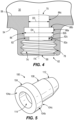
- FIGS. 5 and 6 illustrate the fill valve 100 in detail.
- the fill valve 100 includes a head portion 104 and a body portion 108 between the head portion 104 and a tip portion 112 thereof.
- the fill valve 100 includes a plug receptacle 114 configured to be engaged by the plug 200 ( FIGS. 3 , 9, 11, 13 ).
- the plug receptacle 114 can snugly secure the plug 200 to the fill port 62 such that access to the fill valve 100 is inhibited when the plug 200 engages the fill port 62.
- the fill valve 100 includes a slit 116 extending from the body portion 108 to a tip end 112a of the tip portion 112.
- the pressurized gas from the external gas supply passes through the needle 300 and through the slit 116 prior to entry within the outer storage chamber cylinder 30.
- the head portion 104 includes a first planar surface 104a, an annular outer surface 104b, and a second planar surface 104c.
- the annular outer surface 104b spans the first planar surface 104a and the second planar surface 104c.
- the first planar surface 104a abuts the second axial surface 82c and the second planar surface 104c abuts the second annular portion 86c. Accordingly, during filling and/or refilling, axial force can be transmitted from the fill valve 100 to the fill port 62 while retaining the fill valve 100 in position.
- relative sizes of the annular outer surface 104b and the first annular portion 86a may be selected to permit axial movement or play of the head portion 104 within the first annular portion 86a.
- the annular outer surface 104b may be nominally smaller than an axial length of the first annular portion 86a about the filling axis FA.
- the relative sizes of the annular outer surface 104b and the first annular portion 86a may generally match one another to inhibit axial movement or play of the head portion 104 within the first annular portion 86a.
- the annular outer surface 104b may be dimensioned larger than the first annular portion 86a such that the head portion 104 must be compressed upon entry into the first annular portion 86a.
- the plug receptacle 114 is counter-sunk into the body portion 108.
- the plug receptacle 114 includes a first portion 114a, a second portion 114b, and a transition portion 114c between the first portion 114a and the second portion 114b.
- both the first portion 114a and the second portion 114b are cylindrical in shape.
- the first portion 114a has an inner diameter D6A that is larger than an inner diameter D6 of the second portion 114b (e.g., the inner diameter D6 of the receptacle 114).
- the transition portion 114c transitions the first portion 114a to the second portion 114b.
- the transition portion 114c is frustoconical and includes a linear taper between the inner diameter D6A and the inner diameter D6.
- the second portion 114b terminates, adjacent the tip portion 112, at a counterbore surface 114d in communication with the slit 116.
- the opposite end of the slit 116 is in communication with the tip end 112a of the tip portion 112.
- the counterbore surface 114d is substantially flat (e.g., perpendicular with the filling axis FA).
- an angled (e.g., conical) countersunk surface 614d is adjacent the slit 616 (described in detail below).
- the slit 116 extends a length L1 between the plug receptacle 114 and the tip end 112a of the tip portion 112.
- the length L1 is approximately 3 millimeters. Varying lengths of slits 116 may be employed depending on, for example, dimensions of the needle 300 (see FIG. 15 and discussion thereof below) and the operating pressure of the fastener driver (see Table 1 below).
- the length L1 of the slit 116 may be between 1 millimeter and 5 millimeters. In some embodiments, the length L1 of the slit 116 may be between 2 millimeters and 3 millimeters.
- the fill valve 100 is slightly larger than the conforming surface 86. More specifically, the head portion 104 and the body portion 108, which are generally annularly shaped, have outer diameters D1, D2 ( FIG. 6 ), respectively which are slightly larger than a corresponding inner diameters D3, D4 ( FIG. 4 ) of the conforming surface 86. An outer diameter D2 of the head portion 104 (i.e., a head outer diameter D2) is larger than an outer diameter D1 of the body portion 108 (i.e., a body outer diameter D1). Additionally, when the fill valve 100 is fully seated in the conforming surface 86, at least the tip portion 112 of the fill valve 100 is received in the storage chamber cylinder 30. As illustrated in FIGS.
- the entirety of the tip portion 112, and thus an entirety of the slit 116 may be positioned within the storage chamber cylinder 30 and beyond the inner end 70 of the fill port 62.
- an entirety of the counterbore surface 114d is positioned within the bounds of the storage chamber cylinder 30 (i.e., above the inner end 70 as viewed in FIG. 70).
- the illustrated fill valve 100 is made of an elastic material.
- the fill valve 100 may be made from rubber or another elastic and/or elastomeric material. Accordingly, the fill valve 100 can be press fit into position within the conforming surface 86.
- the annular outer surface 104b along with the outer surface of the body portion 108 create a dual radial seal for abutment against the fill port 62.
- Such a dual radial seal provides multiple surfaces with differing outer diameters for engaging the fill port 62. This strengthens the fill valve 100 itself and permits the fill valve 100 to hold high amounts of pressure within the outer storage chamber cylinder 30.
- pressure within the outer storage chamber cylinder 30 is approximately 120 psi.
- some sporting balls are inflated at 6-8 psi.
- the plug 200 includes a head portion 204 and a body portion 208 between the head portion 204 and a tip portion 212 thereof.
- the head portion 204 is dimensioned (e.g., with a size larger than the fill port 62) to secure the plug 200 with the fill port 62.
- the body portion 208 includes threads 216 which are configured to engage the threaded portion 78 of the fill port 62. As illustrated in the embodiments of FIGS. 8 and 22A , the threads 216 may be fully molded threads 216A that extend around the entirety of the body portion 208 without interruption. In other embodiments, such as the embodiment illustrated in FIG.
- the threads 216 may be interrupted threads 216B that include flattened portions 216C, which interrupt the threads 216 from extending fully around the entirety of the body portion 208.
- the body portion 208 may include any type of interrupted thread or threads 216B.
- the body portion 208 may include threads 216 having helical gaps.
- FIG. 9 illustrates the plug 200 connected to the fill valve 100. In this position, the plug 200 is seated or stopped against the first axial surface 82a of the annular ring 82, and the first planar surface 104a of the head 104 of the fill valve 100 is seated (e.g., stopped) against the second axial surface 82c of the annular ring 82.
- the tip portion 212 has an outer diameter D5 ( FIG. 8 ) nominally greater than the inner diameter D6 ( FIG. 6 ) of the plug receptacle 114.
- the tip portion 212 has a generally constant outer diameter D5. Accordingly, when the threads 216 of the plug 200 are threaded onto the threaded portion 78 of the fill port 62, the tip portion 212 presses against the plug receptacle 114, and the plug receptacle 114 expands to receive the tip portion 212.
- This interference fit promotes strong coupling between the plug 200 and the fill valve 100 during regular use (i.e., between filling and/or refilling operations) of the outer storage chamber cylinder 30.
- FIGS. 10-13 illustrate a plurality of differently shaped interfaces having conforming surfaces 861-864 configured to receive the fill valve 100.
- the conforming surfaces 861, 863 of FIGS. 10 and 12 include shoulders 861a, 863a, which abut the head portions 104 of the fill valves 100 in FIGS. 10 and 12 . This abutment axially retains the fill valve 100 in the fill port 62.
- the conforming surfaces 861, 863 each also include a frustoconical surface 861b, 863b.
- the frustoconical surfaces 861b, 863b permit alignment of the fill valve 100 along a filling axis FA.
- the frustoconical surfaces 861b, 863b provide surfaces for which the head portions 104 of the fill valves 100 to press upon during insertion of the fill valves 100 into the conforming surfaces 861, 863 prior to retention of the of the head portions 104 by the shoulders 861a, 863b.
- the conforming surfaces 862, 864 of FIGS. 11 and 13 do not include shoulders. Rather, the conforming surfaces 862, 864 provide surfaces 862a, 864a onto which the annular outer surface 104b of the head portion 104 of the fill valve 100 can be pressed against.
- the conforming surfaces 862, 864 may require the plugs 200 to provide additional fixing force to retain the fill valves 100 therein.
- a sequence of events occurs during a filling and/or refilling operation of the outer storage chamber cylinder 30.
- the fill valve 100 is positioned within the fill port 62 by inserting the fill valve 100 along the filling axis FA into position with the fill valve 100 engaging the conforming surface 86. This first step of positioning the fill valve 100 is done before initial filling of the outer storage chamber cylinder 30.
- the fill valve 100 may be pressed into position within the fill port 62 without use of an additional tool.
- a plunger tool (T, FIG. 23A ) may be utilized to press the fill valve 100 into position within the fill port 62.
- the needle 300 is moved along the filling axis FA with the needle 300 piercing the slit 116 such that a tip 304 of the needle 300 is received within the outer storage chamber cylinder 30 (see FIG. 15 ).
- the slit 116 is flexible such that the tip 304 of the needle 300 may pierce the slit 116. Once removed, the slit 116 may return to the closed position thereof (as illustrated in FIG. 14 ). While the tip 304 is received within the outer storage chamber cylinder 30, external gas is passed though the needle 300 and through the slit 116 of the fill valve 100 for entrance into the outer storage chamber cylinder 30.
- the external gas extends into the outer storage chamber cylinder 30 along arrows P2 ( FIG. 15 ).
- the needle 300 is retracted along the filling axis FA.
- the pressure within the outer storage chamber cylinder 30 (illustrated as arrows P1, FIG. 14 ) closes the slit 116 and thus the fill valve 100.
- the plug 200 is then inserted into the fill valve 100 with the tip portion 212 engaging the plug receptacle 114.
- the threads 216 are tightened on the threaded portion 78 of the fill port 62.
- the threads 216 hold the plug 200 and thus the fill valve 100 in the closed position.
- the fastener driver 10 is then ready for firing and operation of the lifting assembly 42.
- an adapter 400 may be provided.
- the adapter 400 includes features similar to that of the plug 200 with reference numerals starting at 404.
- the adapter 400 further includes features similar to that of the needle 300 with reference numerals starting at 450.
- the adapter 400 can both pierce the slit 116 for positioning the tip 454 of the needle portion 450 within the outer storage chamber cylinder 30 as well as engaging the threaded portion 78 of the fill port 62 by the threads 416. With such an adapter 400, no seal is made between the adapter 400 and the fill port 62.
- the pressure within the outer storage chamber cylinder 30 forms a seal against the fill valve 100. This forms the seal to inhibit leakage of compressed gas from leaking in an outward direction from the outer storage chamber cylinder 30 through the fill valve 100 and the adapter 400, to the surroundings of the fastener driver 10.
- FIG. 17 illustrates another plug 500 configured for use with a fill valve 600 and the storage chamber cylinder 30.
- the fill valve 600 is similar to the fill valve 100 except the plug receptacle 614 of the fill valve 600 is dimensioned to receive the plug 500. Similar components of the fill valve 600 when compared to the fill valve 100, such as the slit 616 are numbered with '600' series reference numerals.
- the plug 500 includes a head portion 504, a body portion 508 between the head portion 504 and a tip portion 512 thereof.
- the head portion 504 is dimensioned to interconnect the tip 512 and the fill valve 600 such that the outer storage chamber cylinder 30 is sealed from the surroundings by the closing of the slit 616 as well as the interconnection between the tip 512 and the plug receptacle 614 of the fill valve 600.
- the body portion 512 includes threads 516 which are configured to engage the threaded portion 78 of the fill port 62.
- the plug 500 differs from the plug 200 ( FIG. 8 ). As mentioned above, the plug 200 has a generally constant outer diameter D5.
- the fill valve 600 has a generally constant inner diameter D6 which is configured to interfere with the plug 500.
- the tip portion 512 of the plug 500 has a variable outer diameter. As illustrated in FIG.
- the plug 500 has a base diameter D7 which is greater than a tip diameter D8 thereof.
- the tip portion 512 of the plug 500 has a linearly tapered outer diameter.
- Other variable outer diameters of the tip portion 512 are possible, such as non-linearly tapering outer diameters. Otherwise shaped tip portions 512 (e.g., constant diameter, non-constant diameter, otherwise tapered tip portions 512) are also possible.
- the tip portion 512 of the plug 500 Upon insertion of the plug 500 into the fill port 62 and into engagement with the fill valve 600, the tip portion 512 of the plug 500 is inserted at least partially into the plug receptacle 614.
- the tapered outer diameter of the tip portion 512 promotes concentric alignment of the plug 500 relative to the fill valve 600.
- egress of gas from the outer storage chamber cylinder 30 is inhibited.
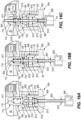
- FIGS. 18A-18C illustrate another fill valve 700, needle 800, and an adapter 900 configured for use with the storage chamber cylinder 30. More specifically, FIGS. 18A-18C illustrate an insertion process of the needle 800 into engagement with the fill valve 700 for providing gas to the storage chamber cylinder 30 while maintaining at least one seal to inhibit egress of gas from the storage chamber cylinder 30.
- the fill valve 700 includes a head portion 704 and a body portion 708 between the head portion 704 and a tip portion 712 thereof.
- the fill valve 700 includes a receptacle 714 configured to be receive the needle 800.
- the plug receptacle 714 has a base inner diameter D9 adjacent the head portion 704, an intermediate inner diameter D10 adjacent the body potion 708, and a tip inner diameter D11 adjacent the tip portion 712.
- the tip inner diameter D11 converges to a slit 716 of the fill valve 700.
- the receptacle 714 of the fill valve 700 is defined by the inner diameters D9-D11.
- the base inner diameter D9 is greater than the intermediate inner diameter D10 and the tip inner diameter D 11.
- the intermediate inner diameter D 10 is approximately the same size as the tip inner diameter D 11. Approximately meaning within +/- 20%.
- the intermediate inner diameter D10 may be within +/- 50% from the tip inner diameter D11.
- Other ratios of the intermediate inner diameter D10 and the inner diameter D11 are possible.
- the receptacle 714 of the fill valve 700 has a rectilinearly tapered inner diameter which is defined by the inner diameters D9-D11.
- Such a taper is configured to guide the needle 800 into alignment with the filling axis FA, and thus the slit 716 of the fill valve 700.
- Other variable inner diameters of the needle receptacles 714 are possible, such as linearly tapering inner diameters and non-linearly tapering (e.g., curved) inner diameters.
- the adapter 900 includes a base 904 and a body 908.
- the base 904 protrudes radially outwardly from the body 908.
- the base 904 and the body 908 together define a cavity 912 configured to receive the needle 800.
- the cavity 912 has a base inner diameter D12 adjacent the base 904, an intermediate inner diameter D13 adjacent the body 908, and a tip inner diameter D14 furthest away from the base 904.
- the tip inner diameter D14 of the adapter 900 is dimensioned with approximately the same size as base inner diameter D9 of the fill valve 700. Approximately meaning within +/- 20%. In other embodiments, the tip inner diameter D14 may be within +/- 50% from the base inner diameter D9. Other ratios of the tip inner diameter D14 and the base inner diameter D9 are possible.
- the cavity 912 is flared between the base inner diameter D12 and the tip inner diameter D14.
- the illustrated cavity 912 varies in diameter along the filling axis FA.
- the illustrated cavity 912 varies in diameter in a non-linear manner along the filling axis FA (e.g., the cavity 912 is generally conical).
- the cavity 912 may be otherwise shaped.
- the adapter 900 further includes threads 916 on the body 908 thereof.
- the threads 916 are configured to engage the threaded portion 78 to secure the adapter 900 in position relative to the fill valve 700 and the storage chamber cylinder 30.
- the head portion 704 of the fill valve 700 is dimensioned in a similar fashion to the head portion 104 of the fill valve 100 such that the head portion 704 can secure the fill valve 700 to the conforming surface 86 of the fill port 62 (See FIG. 7 ).
- the threads 916 extend the entire length of the body 908 in a direction parallel to the longitudinal axis LA, and the threads 916 engage the entirety of the threaded portion 78.
- the threads 916 may be positioned on greater than half of the body 908 and engage greater than half of the threaded portion 78. In other embodiments, the threads 916 may be positioned on other amounts of the body 908, and engage differing proportions of the threaded portion 78.
- the needle 800 includes a tip 804 and a base 806. Between the tip 804 and the base 806, the needle 800 has a cylindrical outer diameter D15.
- the needle 800 further includes, between the tip 804 and the base 806, a projection 808 (i.e., a ball).
- the projection 808 has an outer diameter D16 greater than the cylindrical outer diameter D15 of the remainder of the needle 800.
- the projection 808 is generally annularly shaped, and projects from the needle 800 away (e.g., radially outwardly) from the filling axis FA.
- the projection 808 has a rounded (e.g., curved) annular shape.
- the projection 808 may function to seal the outer storage chamber cylinder 30 from the surroundings.
- the outer diameter D16 is greater than the base inner diameter D12.
- the outer diameter D16 is greater than the tip inner diameter D11. Accordingly, the adapter 900 may serve to align the needle 800 along the filling axis FA during insertion of the needle 800.
- the cylindrical outer diameter D15 is smaller than the base inner diameter D 12, the intermediate inner diameter D13, and the tip inner diameter D14.
- the cylindrical outer diameter D15 is also smaller than the base inner diameter D9, the intermediate inner diameter D10, and the tip inner diameter D11.
- the cylindrical outer diameter D15 is smaller than a largest flexible extent of the slit 716. Accordingly, the needle 800 can pass through the cavity 912 and the receptacle 714 to pierce the slit 716 with the slit 716 forming a seal against the tip 804 thereof in the installed position ( FIG. 18C ).
- the outer diameter D16 is greater than the tip inner diameter D 11.
- the outer diameter D16 is greater than the intermediate inner diameter D10. Accordingly, when the needle 800 is installed ( FIG. 18C ) with the tip 804 projecting into the outer storage chamber cylinder 30, the projection 808 may press against the fill valve 700 and function as a secondary seal in addition to the slit 716. This secondary seal may function during insertion and removal of the needle 800 relative to the fill valve 700. Accordingly, the projection 808 may maintain a seal between the outer storage chamber cylinder 30 and the surroundings as the slit 716 transitions between open ( FIG 18C ) and closed positions ( FIGS. 18A-18B ) thereof.
- FIG. 18A illustrates a first position (e.g., a retracted position) of the needle 800 in contact with the adapter 900.
- a first position e.g., a retracted position
- the tip 804 is received in the plug receptacle 714 of the fill valve 700.
- the remainder of the needle 800, including the projection 808 is not yet positioned in the plug receptacle 114.
- the projection 808 is seated against the cavity 912. In this position, the projection 808 and the cavity 912 continue to align the needle 800 with the filling axis FA.
- the projection 808 Upon further application of force to the needle 800, the projection 808 progresses to the position illustrated in FIG. 18B (e.g., a second position, intermediate position) in which the projection 808 is removed from the cavity 912, and the projection 808 is partially positioned within the receptacle 714. In this position, the tip 804 of the needle 800 contacts the tip portion 712 of the fill valve 700.
- the tip 804 of the needle 800 progresses to pierce the slit 716 and to the position illustrated in FIG. 18C with the tip 804 located within the chamber cylinder 30.
- the projection 808 may press against the tip portion 712 of the fill valve 700 to inhibit further insertion of the needle 800 into the chamber cylinder 30.
- the base 806 of the needle 800 may also contact the base 904 of the adapter 900. In this position, gas may be passed through the needle 800 and into the chamber cylinder 30.
- the reverse process is carried out.
- the needle 800 is retracted along the filling axis FA in reverse of the above-described insertion thereof.
- the projection 808 contacts the fill valve 700 when the needle 800 is fully seated upon the fill valve 700.
- the projection 808 continues to press against the fill valve 700 during retraction of the needle 800 to the position of FIG. 18B .
- the projection 808 maintains the seal with the fill valve 700. Accordingly, the slit 716 can re-seal itself before the projection 808 is removed from contact with the fill valve 700 (e.g., as in the position of FIG. 18B ).
- FIGS. 19A-19C illustrate another fill valve 1000, the needle 800, and another adapter 1100 configured for use with the storage chamber cylinder 30. More specifically, FIGS. 19A-19C illustrate an insertion process of the needle 800 into engagement with the fill valve 1000 for providing gas to the storage chamber cylinder 30 while maintaining at least one seal to inhibit egress of gas from the storage chamber cylinder.
- the fill valve 1000, needle 800, and adapter 1100 function similarly to the fill valve 70, needle 800, and adapter 1000 described above.
- the fill valve 1000 is differently shaped than the fill valve 700.
- the fill valve 1000 generally includes features similarly to the fill valve 700 and including reference numerals in the 1000 series.
- the fill valve 1000 is defined by inner diameters D17-D19.
- a base inner diameter D17 is slightly greater than an intermediate inner diameter D18 and a tip inner diameter D19.
- the base inner diameter D17 may be between 1% and 50% larger than the tip inner diameter D19.
- the base inner diameter D17 is approximately 10% larger than the tip inner diameter D19.
- the base inner diameter D17 linearly increases along the filling axis FA with the intermediate inner diameter D18 being proportionally between the size of the base inner diameter D17 and the tip inner diameter D19.
- the inner diameters D17-D19 define a receptacle 1014 of the fill valve 1000 similar to the receptacle 714 of the fill valve 700.
- Other variable inner diameters of the needle receptacle 1014 are possible, such as rectilinearly tapering inner diameters and non-linearly tapering (e.g., curved) inner diameters.
- the adapter 1100 is differently shaped than the adapter 900.
- the adapter 1100 includes a base 1104 and a body 1108.
- the base 1104 protrudes radially outwardly from the body 1108.
- the base 1104 and the body 1108 together define a through bore 1112 configured to receive the needle 800.
- the illustrated through bore 1112 is linear and extends parallel to the filling axis FA when the adapter 1100 is secured to the storage chamber cylinder 30.
- the through bore 1112 has a diameter D20 which is constant in size along the filling axis FA when the adapter 1100 is secured to the storage chamber cylinder 30.
- the diameter D12 of the through bore 1112 is greater than the outer diameter D15 of the needle 800, and less than the outer diameter D16 of the projection 808.
- the needle 800 is a 16-gauge needle having a nominal outer diameter D15 of approximately 1.27 millimeters. Other sized needles 800 are possible.
- the projection 808 may be a bead affixed to the needle 800 after the adapter 1100 is seated against the base 806.
- the projection 808 is a steel bead affixed to the needle 800 with ethyl cyanoacrylate (e.g., CA glue, commonly known as "super glue").
- the projection 808 may be fixed in other ways (e.g., welded) to the needle 800. Accordingly, the projection 808 may inhibit removal of the adapter 1100 from the needle 800. Accordingly, the needle 800 may be inhibited from removal from the adapter 1100 when the adapter is secured to the storage chamber cylinder 30.
- the adapter 1100 includes other features similar to the adapter 900 but with reference numerals in the 1100 series.
- the adapter 1100 When secured to the storage chamber cylinder 30, the adapter 1100 may extend a lesser extent along the filling axis FA when compared to the adapter 900.
- the body 1108 of the adapter 1100 is axially shorter than the body 908 of the adapter 900. Accordingly, less threads 1116 are required on the body 1108 when compared to the threads 916 of the body 908.
- the threads 1116 extend the entirety of the body 1108. However, the body 1108 is shorter than the body 908.
- the threads 1116 may extend other (e.g., partial) lengths relative to the body 1108. It is understood that the axial length of the threaded portion 78 parallel to the longitudinal axis LA may be adjusted in accordance with axial lengths of the adapter 1100, fill valve 1000, and needle 800 to permit the described sealing functions of the projection 808.
- the fill valve 1000, needle 800, and adapter 1100 function similarly to the fill valve 700, the needle 800, and the adapter 900.
- the projection 808 of the needle 800 may rest against the through bore 1012 of the adapter 1100 in a first position (e.g., retracted position) to inhibit removal of the needle 800 from the adapter 1100.
- the projection 808, having a diameter D16 larger than the diameter D20 of the through bore 1112, is inhibited from being positioned within the through bore 1112.
- the needle 800 After receiving an application of force, the needle 800 progresses to the position illustrated in FIG. 19B (e.g., a second position, intermediate position) in which the projection 808 is removed from the through bore 1012, and the projection 808 is partially received within a receptacle 1014 of the fill valve 1000. In this position, the projection 808 presses against the receptacle 1014 of the fill valve 1000 to provide a secondary seal along with a slit 1016 of the fill valve 1000 for inhibiting passage of gas into and out of the chamber cylinder 30.
- FIG. 19B e.g., a second position, intermediate position
- the needle 800 pierces the slit 1016 of the fill valve 1000, and the tip 804 is located in the chamber cylinder 30.
- the needle 800 is then positioned in the third position (e.g., a fully inserted position) wherein gas may be passed through the needle 800 and into the chamber cylinder 30.
- Table 1 identifies example filling pressures for various fastener drivers 10 having chamber cylinders 30 with the piston 22 in the bottom-dead-center (i.e., BDC) position (illustrated with piston 22, FIG. 3 ) or the top-dead-center (i.e., TDC) position (illustrated with piston 22a, FIG. 3 ).
- BDC bottom-dead-center
- TDC top-dead-center
- Other fill pressures of the chamber cylinders 30 are possible.
- Table 1 Fill Pressure of Chamber Cylinder 30 for Various Fastener Drivers 23ga Pin Nailer 18ga Finish Nailer Narrow Crown Stapler 16ga Finish Nailer 15ga Finish Nailer Framing Nailer Utility Stapler BDC Pressure [psi] 70 56.3 85 64 78 102 112 TDC Pressure [psi] 111 84.5 127.5 110.7 153 164 181
- overfill protection may be employed to inhibit overfilling of the chamber cylinder 30 beyond the above-identified filling pressures in Table 1.
- an operator may repeatedly introduce gas through the needle 800 and into the chamber cylinder 30 while periodically measuring gas pressure within the chamber cylinder 30. If the filling pressure is exceeded, excess gas may be release from the chamber cylinder 30.
- an overfill prevention valve (not shown) may inhibit further passage of compressed air upon reaching the desired fill pressure.
- the overfill prevention valve may be adjustable such that an operator may adjust the overfill prevention valve before use in filling any one of the varieties of the fastener drivers 10 listed in Table 1.
- the needle 800 is retracted along the filling axis FA.
- the projection 808 continues to press against the fill valve 1000 during retraction of the needle 800 to the intermediate position of FIG. 19B .
- the slit 1016 is closed.
- the projection 808 no longer contacts the fill valve 1000.
- the projection 808 maintains the seal with the fill valve 1000. Accordingly, the slit 1016 can re-seal itself before the projection 808 is removed from contact with the fill valve 1000 (e.g., as in the position of FIG. 19A )
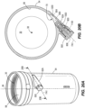
- a fill port 62A may extend along a filling axis FA1 that is offset from the driving axis 38.
- the filling axis FA1 may be transverse to, but not intersecting, the driving axis 38. Accordingly, the filling axis FA1 may be aligned with the inner end 70 of the annular inner wall 58 of any given chamber cylinder 30. In other words, the filling axis FA1 is tangent to the annular inner wall 58 defined by the storage chamber cylinder 30.
- a stem chamber 1200 is a void positioned between the inner end 70 of the annular inner wall 58 and the fill valve 1000, which is seated in the fill port 62A.
- the fill port 62A i.e., at least stem chamber 1200 and needle 800 are dimensioned such that once the projection 808 cracks the fill valve 1000, the tip 804 of the needle 800 is positioned within the stem chamber 1200 and not the chamber cylinder 30.
- FIGS. 21A-21B illustrate another example fill port 62B extending along a filling axis FA2 that is obliquely oriented relative to the driving axis 38.
- FIG. 21B best illustrates an angle AN1 between the filling axis FA2 and the driving axis 38.
- the angle AN1 may be approximately 30 degrees.
- the angle AN1 may be between 15 degrees and 75 degrees.
- the angle AN1 may be between 0 degrees and 90 degrees, or between 90 degrees and 180 degrees.
- the filling axis FA2 intersects the driving axis 38. In other embodiments, the filling axis FA2 need not intersect the driving axis 38.
- the filling axis FA2 may be obliquely oriented relative to but not intersect the driving axis 38.
- the fill port 62B includes a stem chamber 1300 in the form of a void positioned between the inner end 70 of the annular inner wall 58 and the fill valve 1000, which is seated in the fill port 62B.
- the fill port 62B i.e., at least stem chamber 1300 and needle 800 are dimensioned such that once the projection 808 cracks the fill valve 1000, the tip 804 of the needle 800 is positioned within the stem chamber 1300 and not the chamber cylinder 30.
- FIGS. 23A-23B illustrate another example fill valve 1400, fill port 62C, and plug 1500.
- the fill valve 1400 is generally shaped and functions similarly to the fill valve 100, with like reference numerals in the 1400 series.
- the fill port 62C includes a stepped inner surface 63 including an outer portion 63a closest to the outer end 66 of the fill port 62C, an intermediate portion 63b, and an inner portion 63c closest to the inner end 70 of the fill port 62C.
- the intermediate portion 63b is positioned along the filling axis FA between the outer portion 63a and the inner portion 63c.
- a diameter D21 of the outer portion 63a is nominally greater than a diameter D22 of the intermediate portion 63b, and the diameter D22 of the intermediate portion 63b is greater than a diameter D23 of the inner portion 63c.
- the fill valve 1400 includes a slit 1416 configured to receive a needle (e.g., the needle 300) to introduce external gas pressure into the storage chamber cylinder 30.
- the plug 1500 is generally shaped and functions similarly to the plug 200, with like reference numerals in the 1500 series. Namely, the plug 1500 includes a head portion 1504 and a body portion 1508 between the head portion 1504 and a tip portion 1512 thereof.
- the head portion 1504 is generally circular in shape about the filling axis FA and is rounded to limit the height of the head portion 1504 sticking out from outer end 66 of the fill port 62C.
- the plug 1500 includes an aperture 1520 (e.g., a central aperture) dimensioned to receive a tightening tool (e.g., hex key, not shown).
- the tightening tool may be stored onboard the fastener driver 10 for ease of access.
- the aperture 1520 is hexagonal in cross-section perpendicular to the filling axis FA, although other shapes for the central aperture 1520 are possible.
- the illustrated aperture 1520 includes a depression 1524 at an and closest to the tip portion 1512 of the plug 1500.
- the depression 1524 may assist in aligning or locating the tightening tool for engagement with the aperture 1520.
- the depression 1524 is circularly shaped in cross-section, and is slightly tapered in the axial direction. However, in other embodiments, the depression 1524 may be otherwise dimensioned.
- the fill valve 1400 and plug 1500 are secured to one another in part by an intermediate block 1600.
- the intermediate block 1600 includes a cylindrical body 1604 including internal threads 1608 and a cylindrically shaped outer surface 1612.
- the intermediate block 1600 further includes an axial stop 1616 projecting radially inwardly from the cylindrical body 1604.
- the intermediate block 1600 is positioned within the outer portion 63a of the fill port 62C.
- the intermediate block 1600 is configured to secure the fill valve 1400 in position at least partially within the intermediate portion 63b and inner portion 63c of the fill port 62C.
- the fill valve 1400 can be pressed into the intermediate portion 63b and inner portion 63c of the inner surface 63.
- the intermediate block 1600 may be pressed onto the outer portion 63a of the inner surface 63. Pressing the intermediate block 1600 may require a substantial amount of force and once in position, a high amount of friction between the intermediate block 1600 and the inner surface 63 inhibits removal of the fill valve 1400 from the intermediate portion 63b and inner portion 63c.
- the axial stop 1616 of the intermediate block 1600 may press upon a head portion 1404 of the plug 1500.
- the plug 1500 may then optionally be threaded onto the intermediate block 1600 in a similar manner to the threading of the plug 200 onto the threaded portion 78 of the fill port 62 ( FIG. 9 ).
- the fill valve 1400, plug 1500, and intermediate block 1600 may be capable of withstanding a high pressure, for example, a pressure in excess of the pressures listed in Table 1 above.
Landscapes
- Engineering & Computer Science (AREA)
- Mechanical Engineering (AREA)
- General Engineering & Computer Science (AREA)
- Physics & Mathematics (AREA)
- Fluid Mechanics (AREA)
- Portable Nailing Machines And Staplers (AREA)
Abstract
Description
- This application claims priority to co-pending
U.S. Provisional Patent Application No. 63/369,150 filed on July 22, 2022 U.S. Provisional Patent Application No. 63/349,716 filed on June 7, 2022 U.S. Provisional Patent Application No. 63/337,647 filed on May 3, 2022 - The present invention relates to powered fastener drivers, and more specifically to gas spring-powered fastener drivers.
- There are various fastener drivers known in the art for driving fasteners (e.g., nails, tacks, staples, etc.) into a workpiece. These fastener drivers operate utilizing various means known in the art (e.g. compressed air generated by an air compressor, electrical energy, a flywheel mechanism, etc.), but often these designs are met with power, size, and cost constraints.
- The present invention provides, in one aspect, a powered fastener driver. The powered fastener driver includes a piston cylinder, a piston, a driver blade, a lifter, a storage chamber cylinder, a fill port, and a one-piece fill valve. The piston is movable and is positioned within the piston cylinder. The driver blade is attached to the piston and movable therewith between a top-dead-center position and a bottom-dead-center position. The lifter is operable to move the driver blade from a driven position corresponding with the bottom-dead-center position toward a ready position. The storage chamber cylinder encloses the piston cylinder and defines therewith a storage chamber in which compressed gas is stored. The fill port is coupled to the storage chamber cylinder and is in communication with the storage chamber. The one-piece fill valve is at least partially positioned within the fill port. The fill valve includes a slit which, in a closed state, prevents gas in the storage chamber from being discharged to the atmosphere through the fill valve. In an open state of the slit, the slit permits the storage chamber to be refilled with compressed gas through the fill valve. A pressure exerted on a portion of the fill valve in which the slit is defined by compressed gas within the storage chamber maintains the slit in the closed state.
- The present invention provides, in another aspect, a powered fastener driver. The powered fastener driver includes a piston cylinder, a piston, a driver blade, a lifter, a storage chamber cylinder, a fill port, and a one-piece fill valve. The piston is movably positioned within the piston cylinder. The driver blade is attached to the piston and is movable therewith between a top-dead-center position and a bottom-dead-center position. The lifter is operable to move the driver blade from a driven position corresponding with the bottom-dead-center position toward a ready position. The storage chamber cylinder encloses the piston cylinder and defines therewith a storage chamber in which compressed gas is stored. The fill port is coupled to the storage chamber cylinder and is in communication with the storage chamber. The one-piece fill valve is at least partially positioned within the fill port. The fill valve includes a body portion defining a receptacle, a tip portion terminating at a tip end, and a slit extending from the receptacle of the body portion to the tip end of the tip portion. The slit is movable between a closed state in which compressed gas in the storage chamber in prevented from being discharged to the atmosphere through the fill valve, and an open state which permits the storage chamber to be refilled with compressed gas through the fill valve. A pressure exerted on the tip end of the fill valve by compressed gas within the storage chamber maintains the slit in the closed state. The tip portion is configured to be received in the storage chamber cylinder.
- The present invention provides, in another aspect, a powered fastener driver. The gas spring-powered fastener driver includes a piston cylinder, a piston, a driver blade, a lifter, a storage chamber cylinder, a fill port, a one-piece fill valve, and a plug. The piston is movably positioned within the piston cylinder. The drive blade is attached to the piston and is movable therewith between a top-dead-center position and a bottom-dead-center position. The lifter is operable to move the driver blade from a driven position corresponding with the bottom-dead-center position and toward a ready position. The storage chamber cylinder encloses the piston cylinder and defines therewith a storage chamber in which compressed gas is stored. The fill port is coupled to the storage chamber cylinder and is in communication with the storage chamber. The one-piece fill valve is at least partially positioned within the fill port. The fill valve includes a slit which, in a closed state, prevents compressed gas in the storage chamber from being discharged to atmosphere through the fill valve, and in an open state, permits the storage chamber to be refilled with compressed gas through the fill valve. The plug is configured to engage the fill port to inhibit access of the fill valve.
- The present invention provides, in another aspect, a powered fastener driver. The gas spring-powered fastener driver includes a piston cylinder, a piston, a driver blade, a lifter, a storage chamber cylinder, a fill port, a one-piece fill valve, and a plug. The piston is movably positioned within the piston cylinder. The drive blade is attached to the piston and is movable therewith between a top-dead-center position and a bottom-dead-center position. The lifter is operable to move the driver blade from a driven position corresponding with the bottom-dead-center position toward a ready position. The storage chamber cylinder encloses the piston cylinder and defines therewith a storage chamber in which compressed gas is stored. The fill port is coupled to the storage chamber cylinder and is in communication with the storage chamber. The one-piece fill valve having a slit in a tip thereof and an adjacent a receptacle, and is at least partially positioned within the fill port. The fill valve includes a slit, in a closed state, prevents compressed gas in the storage chamber from being discharged to atmosphere through the fill valve, and in an open state, permits the storage chamber to be refilled with compressed gas through the fill valve. The plug has a tip configured to engage the receptacle of the one-piece fill valve to inhibit access of the fill valve.
- The present invention provides, in another aspect, a powered fastener driver. The gas spring-powered fastener driver includes a piston cylinder, a piston, a driver blade, a lifter, a storage chamber cylinder, a fill port, a one-piece fill valve, an adapter, and a needle. The piston is movably positioned within the piston cylinder. The drive blade is attached to the piston and is movable therewith between a top-dead-center position and a bottom-dead-center position. The lifter is operable to move the driver blade from a driven position corresponding with the bottom-dead-center position toward a ready position. The storage chamber cylinder encloses the piston cylinder and defines therewith a storage chamber in which compressed gas is stored. The fill port is coupled to the storage chamber cylinder and is in communication with the storage chamber. The one-piece fill valve has a receptacle. The one-piece fill valve it at least partially positioned within the fill port. The fill valve includes a slit which, in a closed state, prevents compressed gas in the storage chamber from being discharged to atmosphere through the fill valve. In an open state of the slit, the storage chamber is permitted to be refilled with compressed gas through the fill valve. The adapter is coupled to the fill port adjacent the one-piece fill valve. The adapter has a cavity. The needle has a tip and a projection. The tip is configured to pass through the cavity and pierce the slit of the fill valve. The projection is configured to contact the receptacle of the fill valve to prevent compressed gas in the storage chamber from being discharged to atmosphere through the fill valve.
- The present invention provides, in another aspect, a powered fastener driver. The gas spring-powered fastener driver includes a piston cylinder, a piston, a driver blade, a lifter, a storage chamber cylinder, a fill port, and a one-piece fill valve. The piston is movable and is positioned within the piston cylinder. The driver blade is attached to the piston and movable therewith along a driving axis between a top-dead-center position and a bottom-dead-center position. The lifter is operable to move the driver blade from a driven position corresponding with the bottom-dead-center position toward a ready position. The storage chamber cylinder encloses the piston cylinder and defines therewith a storage chamber in which compressed gas is stored. The storage chamber cylinder has an annular inner wall surrounding the driving axis. The fill port is coupled to the storage chamber cylinder and is in communication with the storage chamber. The fill port extends along a filling axis tangent to the annular inner wall. The one-piece fill valve is at least partially positioned within the fill port. The fill valve includes a slit which, in a closed state, prevents gas in the storage chamber from being discharged to the atmosphere through the fill valve. In an open state of the slit, the slit permits the storage chamber to be refilled with compressed gas through the fill valve. A pressure exerted on a portion of the fill valve in which the slit is defined by compressed gas within the storage chamber maintains the slit in the closed state.
- The present invention provides, in another aspect, a powered fastener driver. The gas spring-powered fastener driver includes a piston cylinder, a piston, a driver blade, a lifter, a storage chamber cylinder, a fill port, and a one-piece fill valve. The piston is movable and is positioned within the piston cylinder. The driver blade is attached to the piston and movable therewith along a driving axis between a top-dead-center position and a bottom-dead-center position. The lifter is operable to move the driver blade from a driven position corresponding with the bottom-dead-center position toward a ready position. The storage chamber cylinder encloses the piston cylinder and defines therewith a storage chamber in which compressed gas is stored. The fill port is coupled to the storage chamber cylinder and is in communication with the storage chamber. The fill port extends along a filling axis that is obliquely oriented relative to the driving axis. The one-piece fill valve is at least partially positioned within the fill port. The fill valve includes a slit which, in a closed state, prevents gas in the storage chamber from being discharged to the atmosphere through the fill valve. In an open state of the slit, the slit permits the storage chamber to be refilled with compressed gas through the fill valve. A pressure exerted on a portion of the fill valve in which the slit is defined by compressed gas within the storage chamber maintains the slit in the closed state.
- The present disclosure provides, in another aspect, a powered fastener driver. The gas spring-powered fastener driver includes a piston cylinder, a piston, a drive blade, a lifter, a storage chamber cylinder, a fill port, a one-piece fill valve, and an intermediate block. The piston is movable and is positioned within the piston cylinder. The drive blade is attached to the piston and is movable therewith between a top-dead-center position and a bottom-dead-center position. The lifter is operable to move the driver blade from a driven position corresponding with the bottom-dead-center position toward a ready position. The storage chamber cylinder encloses the piston cylinder and defines therewith a storage chamber in which compressed gas is stored. The fill port is coupled to the storage chamber cylinder and is in communication with the storage chamber. The fill port includes a stepped inner surface. The one-piece fill valve has a head, a body, and a receptacle. The one-piece fill valve is at least partially positioned within the fill port, and includes a slot which, in a closed state, prevents compressed gas in the storage chamber from being discharged to atmosphere through the fill valve and, in an open state, permits the storage chamber to be refilled with compressed gas through the fill valve. The intermediate block is configured to be pressed into the fill port adjacent the one-piece valve. The intermediate block has a cylindrical body and an axial stop projecting radially inwardly from the cylindrical body. The axial stop of the intermediate block is configured to inhibit removal of the fill valve from the fill port.
- The present disclosure provides, in another aspect, a powered fastener driver comprising:
- a piston cylinder;
- a movable piston positioned within the piston cylinder;
- a driver blade attached to the piston and movable therewith between a top-dead-center position and a bottom-dead-center position;
- a lifter operable to move the driver blade from a driven position corresponding with the bottom-dead-center position toward a ready position;
- a storage chamber cylinder enclosing the piston cylinder and defining therewith a storage chamber in which compressed gas is stored;
- a fill port coupled to the storage chamber cylinder and in communication with the storage chamber; and
- a one-piece fill valve at least partially positioned within the fill port, the fill valve including a slit which, in a closed state, prevents compressed gas in the storage chamber from being discharged to atmosphere through the fill valve and, in an open state, permits the storage chamber to be refilled with compressed gas through the fill valve,
- wherein a pressure exerted on a portion of the fill valve in which the slit is defined by compressed gas within the storage chamber maintains the slit in the closed state.
- The fill valve may include a head portion, a body portion, and a tip portion, and wherein the head portion and the body portion may define a receptacle configured to receive a plug which further inhibits egress of air from the storage chamber cylinder.
- The receptacle may include a first portion, a second portion, and a transition portion between the first portion and the second portion, wherein the first portion and the second portion may be cylindrical in shape and have a first inner diameter and a second inner diameter, respectively, which are different from one another, and wherein the transition portion may be tapered between the first inner diameter and the second inner diameter.
- The head portion may be generally annularly shaped and includes a head outer diameter, and the body portion may be generally annularly shaped and includes a body outer diameter, and wherein the head outer diameter may be larger than the body outer diameter.
- The fill valve may include a tip end and a receptacle with a counterbore surface, and wherein the slit of the fill valve may be in communication with the tip end and the counterbore surface.
- The counterbore surface may be substantially flat.
- The slit may have a length between the tip end and the receptacle between 1 millimeter and 5 millimeters.
- The present disclosure provides, in another aspect, a powered fastener driver comprising:
- a piston cylinder;
- a movable piston positioned within the piston cylinder;
- a driver blade attached to the piston and movable therewith between a top-dead-center position and a bottom-dead-center position;
- a lifter operable to move the driver blade from a driven position corresponding with the bottom-dead-center position toward a ready position;
- a storage chamber cylinder enclosing the piston cylinder and defining therewith a storage chamber in which compressed gas is stored;
- a fill port coupled to the storage chamber cylinder and in communication with the storage chamber; and
- a one-piece fill valve at least partially positioned within the fill port, the fill valve including
- a body portion defining a receptacle,
- a tip portion terminating at a tip end, and
- a slit extending from the receptacle of the body portion to the tip end of the tip portion, the slit being movable between a closed state in which compressed gas in the storage chamber in prevented from being discharged to atmosphere through the fill valve, and an open state which permits the storage chamber to be refilled with compressed gas through the fill valve,
wherein the tip portion is configured to be received in the storage chamber cylinder. - The fill port may include a conforming surface configured to receive the fill valve by an interference fit.
- The conforming surface may include a first annular portion having a first diameter and a second annular portion having a second diameter, wherein the first annular portion may be configured to receive at least the body portion of the fill valve, and wherein the second annular portion may be configured to receive at least the head portion of the fill valve.
- The fill port may further comprise an annular ring having a first axial surface, an annular surface, and a second axial surface, and wherein the first axial surface may be configured to provide a stop for a plug, and the second axial surface may be configured to provide a stop for the fill valve.
- An entirety of the slit may be positioned within the storage chamber cylinder.
- The receptacle may include a counterbore surface which may be positioned entirely within the storage chamber cylinder.
- The present disclosure provides, in another aspect, a powered fastener driver comprising:
- a piston cylinder;
- a movable piston positioned within the piston cylinder;
- a driver blade attached to the piston and movable therewith between a top-dead-center position and a bottom-dead-center position;
- a lifter operable to move the driver blade from a driven position corresponding with the bottom-dead-center position toward a ready position;
- a storage chamber cylinder enclosing the piston cylinder and defining therewith a storage chamber in which compressed gas is stored;
- a fill port coupled to the storage chamber cylinder and in communication with the storage chamber;
- a one-piece fill valve at least partially positioned within the fill port, the fill valve including a slit which, in a closed state, prevents compressed gas in the storage chamber from being discharged to atmosphere through the fill valve and, in an open state, permits the storage chamber to be refilled with compressed gas through the fill valve; and
- a plug configured to engage the fill port to inhibit access of the fill valve.
- The fill port may include a threaded portion, and the plug may include a body portion including threads, and wherein the threads of the body portion may be configured to engage the threaded portion of the fill port to secure the plug to the fill port.
- The threads of the body portion may be interrupted threads including flattened portions.
- The fill valve may include a receptacle, and the plug may further include a tip portion configured engage the receptacle to secure the fill valve to the fill port.
- The receptacle may include an inner diameter and the tip portion of the plug may include an outer diameter nominally greater than the inner diameter.
- The plug may include a head portion dimensioned with a size larger than the fill port to secure the plug with the fill port.
- The plug may be removable from the fill port to permit access to the fill valve.
- The present disclosure provides, in another aspect, a powered fastener driver comprising:
- a piston cylinder;
- a movable piston positioned within the piston cylinder;
- a drive blade attached to the piston and movable therewith between a top-dead-center position and a bottom-dead-center position;
- a lifter operable to move the driver blade from a driven position corresponding with the bottom-dead-center position toward a ready position;
- a storage chamber cylinder enclosing the piston cylinder and defining therewith a storage chamber in which compressed gas is stored;
- a fill port coupled to the storage chamber cylinder and in communication with the storage chamber;
- a one-piece fill valve having a slit in a tip thereof and an adjacent receptacle, the one-piece fill valve at least partially positioned within the fill port, the slit, in a closed state, prevents compressed gas in the storage chamber from being discharged to atmosphere through the fill valve and, in an open state, permits the storage chamber to be refilled with compressed gas through the fill valve, and
- a plug having a tip configured to engage the receptacle of the one-piece fill valve to inhibit access of the fill valve.
- The fill port may include a threaded portion, and the plug may include a body portion including threads, and wherein the threads of the body portion may be configured to engage the threaded portion of the fill port to secure the plug to the fill port.
- The receptacle may include an inner diameter and the tip of the plug may include an outer diameter nominally greater than the inner diameter.
- The tip of the plug may have a variable outer diameter.
- The tip of the plug may have a linearly tapered outer diameter.
- The tip may be generally cylindrically shaped.
- The present disclosure provides, in another aspect, a powered fastener driver comprising:
- a piston cylinder;
- a movable piston positioned within the piston cylinder;
- a drive blade attached to the piston and movable therewith between a top-dead-center position and a bottom-dead-center position;
- a lifter operable to move the driver blade from a driven position corresponding with the bottom-dead-center position toward a ready position;
- a storage chamber cylinder enclosing the piston cylinder and defining therewith a storage chamber in which compressed gas is stored;
- a fill port coupled to the storage chamber cylinder and in communication with the storage chamber;
- a one-piece fill valve having a receptacle, the one-piece fill valve at least partially positioned within the fill port, the fill valve including a slit which, in a closed state, prevents compressed gas in the storage chamber from being discharged to atmosphere through the fill valve and, in an open state, permits the storage chamber to be refilled with compressed gas through the fill valve,
- an adapter coupled to the fill port adjacent the one-piece fill valve, the adapter having a cavity,
- a needle having a tip and a projection, the tip being configured to pass through the cavity and pierce the slit of the fill valve and the projection being configured to contact the receptacle of the fill valve to prevent compressed gas in the storage chamber from being discharged to atmosphere through the fill valve.
- The fill port may include a threaded portion and the adapter may include a body portion having threads, and wherein the threads of the body portion may be configured to engage the threaded portion of the fill port to secure the adapter to the fill port.
- The adapter may include a base and a body, wherein the cavity may include a base inner diameter adjacent the base and a tip inner diameter furthest away from the base, and wherein the tip inner diameter may be larger than the base inner diameter.
- The fill valve further includes a base, a body, and a tip, the receptacle of the fill valve including an inner diameter at least partially smaller than a diameter defined by the projection of the needle.
- The receptacle may include a tapered inner diameter.
- The inner diameter may be tapered to guide the needle into alignment with the slit.
- The adapter may include a through bore having a constant size.
- The present disclosure provides, in another aspect, a powered fastener driver comprising:
- a piston cylinder;
- a movable piston positioned within the piston cylinder;
- a driver blade attached to the piston and movable therewith along a driving axis between a top-dead-center position and a bottom-dead-center position;
- a lifter operable to move the driver blade from a driven position corresponding with the bottom-dead-center position toward a ready position;
- a storage chamber cylinder enclosing the piston cylinder and defining therewith a storage chamber in which compressed gas is stored, the storage chamber cylinder having an annular inner wall surrounding the driving axis;
- a fill port coupled to the storage chamber cylinder and in communication with the storage chamber, the fill port extending along a filling axis tangent to the annular inner wall; and
- a one-piece fill valve at least partially positioned within the fill port, the fill valve including a slit which, in a closed state, prevents compressed gas in the storage chamber from being discharged to atmosphere through the fill valve and, in an open state, permits the storage chamber to be refilled with compressed gas through the fill valve,
- wherein a pressure exerted on a portion of the fill valve in which the slit is defined by compressed gas within the storage chamber maintains the slit in the closed state.
- The filling axis may be tangent to the driving axis.
- The filling axis may be offset from the driving axis.
- The storage chamber cylinder may include an annular inner wall and the fastener driver may further include a stem chamber positioned between the inner wall and the fill valve.
- A tip of a needle may be configured to crack the fill valve and be positioned within the stem chamber, without entering the storage chamber cylinder.
- The present disclosure provides, in another aspect, a powered fastener driver comprising:
- a piston cylinder;
- a movable piston positioned within the piston cylinder;
- a driver blade attached to the piston and movable therewith along a driving axis between a top-dead-center position and a bottom-dead-center position;
- a lifter operable to move the driver blade from a driven position corresponding with the bottom-dead-center position toward a ready position;
- a storage chamber cylinder enclosing the piston cylinder and defining therewith a storage chamber in which compressed gas is stored;
- a fill port coupled to the storage chamber cylinder and in communication with the storage chamber, the fill port extending along a filling axis that is obliquely oriented relative to the driving axis; and
- a one-piece fill valve at least partially positioned within the fill port, the fill valve including a slit which, in a closed state, prevents compressed gas in the storage chamber from being discharged to atmosphere through the fill valve and, in an open state, permits the storage chamber to be refilled with compressed gas through the fill valve,
- wherein a pressure exerted on a portion of the fill valve in which the slit is defined by compressed gas within the storage chamber maintains the slit in the closed state.
- The filling axis may be angled relative to the driving axis at an angle between 0 degrees and 90 degrees.
- The filling axis may be angled relative to the driving axis at an angle between 15 degrees and 75 degrees.
- The filling axis may intersect the driving axis.
- The filling axis may be obliquely oriented relative to the driving axis but does not intersect the driving axis.
- The storage chamber cylinder may include an annular inner wall, and wherein the fastener driver may further include a stem chamber positioned between the inner wall and the fill valve.
- A tip of a needle may be configured to crack the fill valve and be positioned within the stem chamber without entering the storage chamber cylinder.
- The present disclosure provides, in another aspect, a powered fastener driver comprising:
- a piston cylinder;
- a movable piston positioned within the piston cylinder;
- a drive blade attached to the piston and movable therewith between a top-dead-center position and a bottom dead-center position;
- a lifter operable to move the driver blade from a driven position corresponding with the bottom-dead-center position toward a ready position;
- a storage chamber cylinder enclosing the piston cylinder and defining therewith a storage chamber in which compressed gas is stored;
- a fill port coupled to the storage chamber cylinder and in communication with the storage chamber, the fill port including a stepped inner surface;
- a one-piece fill valve having a head, a body, and a receptacle, the one-piece fill valve at least partially positioned within the fill port, the fill valve including a slit which, in a closed state, prevents compressed gas in the storage chamber from being discharged to atmosphere through the fill valve and, in an open state, permits the storage chamber to be refilled with compressed gas through the fill valve,
- an intermediate block configured to be pressed into the fill port adjacent the one-piece valve, the intermediate block having a cylindrical body and an axial stop projecting radially inwardly from the cylindrical body, the axial stop of the intermediate block being configured to inhibit removal of the fill valve from the fill port.
- The stepped inner surface of the fill port may include an outer portion, an inner portion, and an intermediate portion between the outer portion and the inner portion, and wherein the outer portion, inner portion, and intermediate portion may each have different diameters.
- The outer portion may include a diameter nominally greater than a diameter of the intermediate portion, and wherein the diameter of the intermediate portion may be nominally greater than a diameter of the inner portion.
- The cylindrical body of the intermediate block may be press-fit onto the outer portion of the fill port.
- The intermediate block may include threads configured to engage corresponding threads of a plug.
- The plug may include an aperture configured to receive a tightening tool, and wherein the aperture may have a cross-sectional shape corresponding to the tightening tool.
- The aperture may further include a depression at an end closest to the tip portion of the plug to facilitate alignment of the tightening tool with the aperture.
- Other features and aspects of the invention will become apparent by consideration of the following detailed description and accompanying drawings.
-
-
FIG. 1 is a perspective view of a gas spring-powered fastener driver. -
FIG. 2 is a cross-sectional view of the gas spring-powered fastener driver taken along section line 2-2 inFIG. 1 . -
FIG. 3 is another cross-sectional view of the gas spring-powered fastener driver including a fill valve and a plug. -
FIG. 4 is an enlarged view of a fill port of a storage chamber cylinder of the gas spring-powered fastener driver ofFIG. 3 . -
FIG. 5 is a perspective view of a fill valve configured for use with the storage chamber ofFIG. 4 . -
FIG. 6 is a cross-sectional view of the fill valve ofFIG. 5 . -
FIG. 7 is a cross-sectional view of the fill valve ofFIG. 5 engaged with the fill port ofFIG. 4 . -
FIG. 8 is a cross-sectional view of a plug configured for use with the storage chamber ofFIG. 4 . -
FIG. 9 is a cross-sectional view of the plug and the fill valve engaged with the fill port ofFIG. 4 . -
FIG. 10 is an alternate embodiment of a fill valve and a fill port. -
FIG. 11 is another alternate embodiment of a fill valve, a fill port, and a plug. -
FIG. 12 is another alternate embodiment of a fill valve and a fill port. -
FIG. 13 is another alternate embodiment of a fill valve, a fill port, and a plug. -
FIG. 14 is a schematic view of the fill valve inhibiting egress of pressure from within the outer storage chamber cylinder. -
FIG. 15 is a schematic view of the fill valve permitting ingress of pressure from the surroundings of the fastener driver into the outer storage chamber cylinder. -
FIG. 16 is a schematic view of an adapter configured for use with the fill port ofFIG. 4 . -
FIG. 17 is a cross-sectional view of another fill valve and plug configured for use with the storage chamber ofFIG. 4 -
FIG. 18A is a cross-sectional view of the fill valve, needle, and adapter with the needle positioned within the adapter. -
FIG. 18B is another cross-sectional view of the fill valve, needle, and adapter ofFIG. 18A with the needle advanced into the fill valve. -
FIG. 18C is another cross-sectional view of the fill valve, needle, and adapter ofFIG. 18A with the needle advanced into the storage chamber. -
FIG. 19A is a cross-sectional view of another fill valve, needle, and adapter with the needle positioned within the adapter. -
FIG. 19B is another cross-sectional view of the fill valve, needle, and adapter ofFIG. 19A with the needle advanced into the fill valve. -
FIG. 19C is another cross-sectional view of the fill valve, needle, and adapter ofFIG. 19C with the needle advanced into the fill valve. -
FIG. 20A is a perspective view of a fill valve and an adapter extending transverse to a driving axis of a storage chamber cylinder. -
FIG. 20B is a cross-sectional view of the fill valve and adapter ofFIG. 20A . -
FIG. 21A is a perspective view of a fill valve and an adapter which are obliquely oriented relative to a driving axis of a storage chamber cylinder. -
FIG. 21B is a cross-sectional view of the fill valve and adapter ofFIG. 21A . -
FIG. 22A is a side view of a plug including fully molded threads. -
FIG. 22B is a side view of an alternate plug including interrupted threads. -
FIG. 23A is a cross-sectional view of a fill valve, adapter, and intermediate block. -
FIG. 23B is another cross-sectional view of the fill valve, adapter, and intermediate block ofFIG. 23A . - Before any embodiments of the invention are explained in detail, it is to be understood that the invention is not limited in its application to the details of construction and the arrangement of components set forth in the following description or illustrated in the following drawings. The invention is capable of other embodiments and of being practiced or of being carried out in various ways. Also, it is to be understood that the phraseology and terminology used herein is for the purpose of description and should not be regarded as limiting.
- With reference to
FIG. 1 , a gas spring-poweredfastener driver 10 is operable to drive fasteners (e.g., nails, tacks, staples, etc.) held within amagazine 14 into a workpiece W.FIG. 2 illustrates some of the internal components of thefastener driver 10. Thefastener driver 10 includes apiston cylinder 18 and amoveable drive piston 22 positioned within the piston cylinder 18 (FIG. 2 ). Thefastener driver 10 further includes adriver blade 26 that is attached to thepiston 22 and moveable therewith. During regular use, thefastener driver 10 does not require an external source of fluid (e.g., gas, air) pressure. Rather, thefastener driver 10 includes an outerstorage chamber cylinder 30 of pressurized gas in communication with thepiston cylinder 18. The outerstorage chamber cylinder 30 defines astorage chamber 31 in which compressed gas is stored. Thestorage chamber 31 is in fluid communication with thepiston cylinder 18. In the illustrated embodiment, thestorage chamber cylinder 30 is coaxial with thepiston cylinder 18, thedrive piston 22, and thedriver blade 26 along a drivingaxis 38. Thepiston 22 and thus thedriver blade 26 are movable along the drivingaxis 38 between a bottom-dead-center (i.e., BDC) position (illustrated withpiston 22,FIG. 3 ) and a top-dead-center (i.e., TDC) position (illustrated withpiston 22a,FIG. 3 ). - With reference to
FIG. 2 , thecylinder 18 and thedriver blade 26 define a driving axis 38 (FIG. 2 ). During a driving cycle, thedriver blade 26 and thepiston 22 are moveable between the top-dead-center (i.e., TDC) position and a driven or bottom-dead-center (BDC) position (piston 22,FIG. 3 ). Thefastener driver 10 further includes a lifting assembly 42 (FIG. 2 ), which is powered by amotor 46, and which is operable to move thedriver blade 26 from the driven position to the TDC position (piston 22,FIG. 3 ). - In operation, the lifting
assembly 42 drives thepiston 22 and thedriver blade 26 toward the TDC position by energizing themotor 46. As thepiston 22 and thedriver blade 26 are driven toward the TDC position, the gas above thepiston 22 and the gas within thestorage chamber cylinder 30 is compressed. Prior to reaching the TDC position, themotor 46 is deactivated and thepiston 22 and thedriver blade 26 are held in a ready position, which is located between the TDC and the BDC or driven positions, until being released by user activation of a trigger 48 (FIG. 1 ). When released, the compressed gas above thepiston 22 and within thestorage chamber cylinder 30 drives thepiston 22 and thedriver blade 26 to the driven position, thereby driving a fastener into the workpiece. The illustratedfastener driver 10 therefore operates on a gas spring principle utilizing the liftingassembly 42 and thepiston 22 to further compress the gas within thecylinder 18 and thestorage chamber cylinder 30. Further detail regarding the structure and operation of thefastener driver 10 is provided below. - With reference to
FIG. 3 , thepiston cylinder 18 has an annular inner wall (i.e., an inner side) 50 configured to guide thepiston 22 along the drivingaxis 38. The outerstorage chamber cylinder 30 has an annular outer wall (i.e., an outer side) 54 which faces away from the drivingaxis 38 and an opposite annular inner wall (i.e., an inner side) 58 which faces towards the drivingaxis 38. In the illustrated embodiment, the outerstorage chamber cylinder 30 is metal. Other materials are possible. -
FIG. 3 further illustrates the annularouter wall 54 and the annularinner wall 58 of the outerstorage chamber cylinder 30.FIG. 3 also illustrates afill port 62 within the outerstorage chamber cylinder 30. Thefill port 62 spans the annularouter wall 54 and the annularinner wall 58. Thefill port 62 is most clearly illustrated inFIG. 4 . As illustrated inFIG. 4 , thefill port 62 includes anouter end 66 adjacent the annularouter wall 54 and an oppositeinner end 70 adjacent the annularinner wall 58. As illustrated inFIG. 3 , thefill port 62 is configured to receive thefill valve 100 therein. In the illustrated embodiment, thefill valve 100 may be made of an elastomer such as a natural rubber, a synthetic rubber, or the like. Thefill valve 100 selectively permits compressed gas from a remote source (e.g., a compressed gas tank) to fill the outerstorage chamber cylinder 30. A threadedplug 200 may selectively engage thefill port 62. Theplug 200 may inhibit access to thefill valve 100 when theplug 200 engages thefill port 62. During a refilling operation, theplug 200 may be removed from thefill port 62, and a needle 300 (FIG. 15 ) can project through thefill port 62 and thefill valve 100. Theneedle 300 can then be connected to an external gas supply (e.g., the compressed gas tank) for introducing gas into the outerstorage chamber cylinder 30. In the embodiment illustrated inFIG. 3 , thefill port 62, plug 200, and fillvalve 100 are each directed or oriented along a filling axis FA that is perpendicular to the drivingaxis 38. - Other elements may replace the
needle 300 for introducing gas (i.e., pressure) into the outerstorage chamber cylinder 30. For example, a check valve can otherwise apply pressure to the up-stream direction of the fill valve 100 (e.g., to introduce gas into the outer storage chamber cylinder 30). Theneedle 300 or check valve may also be used to relieve pressure from the outerstorage chamber cylinder 30 to the environment of the fastener driver 10 (e.g., in a downstream direction). Once all gas is removed from the outerstorage chamber cylinder 30, thefill valve 100 is configured to hold vacuum pressure of the outerstorage chamber cylinder 30. In doing so, thefill valve 100 prevents ingress of gas into the outerstorage chamber cylinder 30. In some embodiments, thefill valve 100 is operable to hold vacuum pressure by itself. In other embodiments (not shown), fill adapters may engage thefill valve 100 to hold vacuum pressure. Thefill valve 100 of the illustrated embodiment is a one-piece fill valve 100. Thefill valve 100 may also be described as a duckbill valve or a self-sealing valve. Operation and geometries of the one-piece fill valve 100 will be described in detail below. - The
fill port 62 defines a passageway 74 (FIG. 4 ) extending from theouter end 66 to theinner end 70. Thefill port 62 generally projects outwardly from the outerstorage chamber cylinder 30. Theinner end 70 is in fluid communication with the outerstorage chamber cylinder 30. Thefill port 62 includes a threadedportion 78 adjacent theouter end 66. The threadedportion 78 is provided as an interior surface within thefill port 62. The threadedportion 78 terminates adjacent anannular ring 82. Theannular ring 82 has a firstaxial surface 82a, anannular surface 82b, and a secondaxial surface 82c. The firstaxial surface 82a is closer to theouter end 66 than the secondaxial surface 82c. The secondaxial surface 82c is closer to theinner end 70 than the firstaxial surface 82a. Theannular surface 82b spans the firstaxial surface 82a and the secondaxial surface 82c. In the illustrated embodiment, theannular surface 82b has an inner diameter generally matching an inner diameter D3 of the secondannular portion 86c. The secondaxial surface 82c abuts a conformingsurface 86 of thefill port 62. The conformingsurface 86 is shaped similarly to thefill valve 100. The conformingsurface 86 includes a firstannular portion 86a, ashoulder 86b, and a secondannular portion 86c. The firstannular portion 86a is located adjacent the secondaxial surface 82c. The secondannular portion 86c terminates at theinner end 70. The illustrated firstannular portion 86a has a diameter D4 larger than the diameter D3 of the secondannular portion 86c. Thefill port 62, thefill valve 100, and the conformingsurface 86 may be otherwise shaped. -
FIGS. 5 and6 illustrate thefill valve 100 in detail. Thefill valve 100 includes ahead portion 104 and abody portion 108 between thehead portion 104 and atip portion 112 thereof. Thefill valve 100 includes aplug receptacle 114 configured to be engaged by the plug 200 (FIGS. 3 ,9, 11, 13 ). Theplug receptacle 114 can snugly secure theplug 200 to thefill port 62 such that access to thefill valve 100 is inhibited when theplug 200 engages thefill port 62. Thefill valve 100 includes aslit 116 extending from thebody portion 108 to atip end 112a of thetip portion 112. The pressurized gas from the external gas supply passes through theneedle 300 and through theslit 116 prior to entry within the outerstorage chamber cylinder 30. - As shown in
FIG. 6 , thehead portion 104 includes a firstplanar surface 104a, an annularouter surface 104b, and a secondplanar surface 104c. The annularouter surface 104b spans the firstplanar surface 104a and the secondplanar surface 104c. When thefill valve 100 is received in thefill port 62, the firstplanar surface 104a abuts the secondaxial surface 82c and the secondplanar surface 104c abuts the secondannular portion 86c. Accordingly, during filling and/or refilling, axial force can be transmitted from thefill valve 100 to thefill port 62 while retaining thefill valve 100 in position. In some preferred embodiments, relative sizes of the annularouter surface 104b and the firstannular portion 86a may be selected to permit axial movement or play of thehead portion 104 within the firstannular portion 86a. In these embodiments, the annularouter surface 104b may be nominally smaller than an axial length of the firstannular portion 86a about the filling axis FA. In other embodiments, the relative sizes of the annularouter surface 104b and the firstannular portion 86a may generally match one another to inhibit axial movement or play of thehead portion 104 within the firstannular portion 86a. In still other embodiments, the annularouter surface 104b may be dimensioned larger than the firstannular portion 86a such that thehead portion 104 must be compressed upon entry into the firstannular portion 86a. - With reference to the
fill valve 100 ofFIGS. 5 and6 , theplug receptacle 114 is counter-sunk into thebody portion 108. Theplug receptacle 114 includes afirst portion 114a, asecond portion 114b, and atransition portion 114c between thefirst portion 114a and thesecond portion 114b. In the illustrated embodiment, both thefirst portion 114a and thesecond portion 114b are cylindrical in shape. Thefirst portion 114a has an inner diameter D6A that is larger than an inner diameter D6 of thesecond portion 114b (e.g., the inner diameter D6 of the receptacle 114). Thetransition portion 114c transitions thefirst portion 114a to thesecond portion 114b. In the illustrated embodiment, thetransition portion 114c is frustoconical and includes a linear taper between the inner diameter D6A and the inner diameter D6. In the embodiment ofFIG. 6 , thesecond portion 114b terminates, adjacent thetip portion 112, at acounterbore surface 114d in communication with theslit 116. The opposite end of theslit 116 is in communication with thetip end 112a of thetip portion 112. In the illustrated embodiment (FIG. 6 ), thecounterbore surface 114d is substantially flat (e.g., perpendicular with the filling axis FA). In contrast, in other embodiments such as thefill valve 600 illustrated inFIG. 17 , an angled (e.g., conical) countersunksurface 614d is adjacent the slit 616 (described in detail below). - With continued reference to the
fill valve 100 ofFIGS. 5 and6 , theslit 116 extends a length L1 between theplug receptacle 114 and thetip end 112a of thetip portion 112. In the illustrated embodiment, the length L1 is approximately 3 millimeters. Varying lengths ofslits 116 may be employed depending on, for example, dimensions of the needle 300 (seeFIG. 15 and discussion thereof below) and the operating pressure of the fastener driver (see Table 1 below). For example, in other embodiments, the length L1 of theslit 116 may be between 1 millimeter and 5 millimeters. In some embodiments, the length L1 of theslit 116 may be between 2 millimeters and 3 millimeters. - As best illustrated in
FIG. 7 , thefill valve 100 is slightly larger than the conformingsurface 86. More specifically, thehead portion 104 and thebody portion 108, which are generally annularly shaped, have outer diameters D1, D2 (FIG. 6 ), respectively which are slightly larger than a corresponding inner diameters D3, D4 (FIG. 4 ) of the conformingsurface 86. An outer diameter D2 of the head portion 104 (i.e., a head outer diameter D2) is larger than an outer diameter D1 of the body portion 108 (i.e., a body outer diameter D1). Additionally, when thefill valve 100 is fully seated in the conformingsurface 86, at least thetip portion 112 of thefill valve 100 is received in thestorage chamber cylinder 30. As illustrated inFIGS. 7 and9 , the entirety of thetip portion 112, and thus an entirety of theslit 116, may be positioned within thestorage chamber cylinder 30 and beyond theinner end 70 of thefill port 62. In the illustrated embodiment, an entirety of thecounterbore surface 114d is positioned within the bounds of the storage chamber cylinder 30 (i.e., above theinner end 70 as viewed in FIG. 70). - The illustrated
fill valve 100 is made of an elastic material. Thefill valve 100 may be made from rubber or another elastic and/or elastomeric material. Accordingly, thefill valve 100 can be press fit into position within the conformingsurface 86. As a result of these interference fits, the annularouter surface 104b along with the outer surface of thebody portion 108 create a dual radial seal for abutment against thefill port 62. Such a dual radial seal provides multiple surfaces with differing outer diameters for engaging thefill port 62. This strengthens thefill valve 100 itself and permits thefill valve 100 to hold high amounts of pressure within the outerstorage chamber cylinder 30. In the illustrated embodiment, pressure within the outerstorage chamber cylinder 30 is approximately 120 psi. For reference, some sporting balls are inflated at 6-8 psi. - As shown in
FIGS. 8 and 9 , theplug 200 includes ahead portion 204 and abody portion 208 between thehead portion 204 and atip portion 212 thereof. Thehead portion 204 is dimensioned (e.g., with a size larger than the fill port 62) to secure theplug 200 with thefill port 62. Thebody portion 208 includesthreads 216 which are configured to engage the threadedportion 78 of thefill port 62. As illustrated in the embodiments ofFIGS. 8 and22A , thethreads 216 may be fully molded threads 216A that extend around the entirety of thebody portion 208 without interruption. In other embodiments, such as the embodiment illustrated inFIG. 22B , thethreads 216 may be interrupted threads 216B that include flattenedportions 216C, which interrupt thethreads 216 from extending fully around the entirety of thebody portion 208. In other embodiments, thebody portion 208 may include any type of interrupted thread or threads 216B. For example, thebody portion 208 may includethreads 216 having helical gaps.FIG. 9 illustrates theplug 200 connected to thefill valve 100. In this position, theplug 200 is seated or stopped against the firstaxial surface 82a of theannular ring 82, and the firstplanar surface 104a of thehead 104 of thefill valve 100 is seated (e.g., stopped) against the secondaxial surface 82c of theannular ring 82. With theplug 200 connected to thefill valve 100, theplug 200 inhibits air from within thestorage chamber cylinder 30 from egress out of thefill valve 100 and to the surroundings of thefastener driver 10. Thetip portion 212 has an outer diameter D5 (FIG. 8 ) nominally greater than the inner diameter D6 (FIG. 6 ) of theplug receptacle 114. In the illustrated embodiment, thetip portion 212 has a generally constant outer diameter D5. Accordingly, when thethreads 216 of theplug 200 are threaded onto the threadedportion 78 of thefill port 62, thetip portion 212 presses against theplug receptacle 114, and theplug receptacle 114 expands to receive thetip portion 212. This interference fit promotes strong coupling between theplug 200 and thefill valve 100 during regular use (i.e., between filling and/or refilling operations) of the outerstorage chamber cylinder 30. -
FIGS. 10-13 illustrate a plurality of differently shaped interfaces having conforming surfaces 861-864 configured to receive thefill valve 100. The conformingsurfaces FIGS. 10 and 12 includeshoulders head portions 104 of thefill valves 100 inFIGS. 10 and 12 . This abutment axially retains thefill valve 100 in thefill port 62. The conformingsurfaces frustoconical surface frustoconical surfaces fill valve 100 along a filling axis FA. Thefrustoconical surfaces head portions 104 of thefill valves 100 to press upon during insertion of thefill valves 100 into the conformingsurfaces head portions 104 by theshoulders surfaces FIGS. 11 and 13 do not include shoulders. Rather, the conformingsurfaces surfaces outer surface 104b of thehead portion 104 of thefill valve 100 can be pressed against. The conformingsurfaces plugs 200 to provide additional fixing force to retain thefill valves 100 therein. - A sequence of events occurs during a filling and/or refilling operation of the outer
storage chamber cylinder 30. First, thefill valve 100 is positioned within thefill port 62 by inserting thefill valve 100 along the filling axis FA into position with thefill valve 100 engaging the conformingsurface 86. This first step of positioning thefill valve 100 is done before initial filling of the outerstorage chamber cylinder 30. In some embodiments, thefill valve 100 may be pressed into position within thefill port 62 without use of an additional tool. In other embodiments, a plunger tool (T,FIG. 23A ) may be utilized to press thefill valve 100 into position within thefill port 62. During filling and/or refilling of the outerstorage chamber cylinder 30, theneedle 300 is moved along the filling axis FA with theneedle 300 piercing theslit 116 such that atip 304 of theneedle 300 is received within the outer storage chamber cylinder 30 (seeFIG. 15 ). Theslit 116 is flexible such that thetip 304 of theneedle 300 may pierce theslit 116. Once removed, theslit 116 may return to the closed position thereof (as illustrated inFIG. 14 ). While thetip 304 is received within the outerstorage chamber cylinder 30, external gas is passed though theneedle 300 and through theslit 116 of thefill valve 100 for entrance into the outerstorage chamber cylinder 30. The external gas extends into the outerstorage chamber cylinder 30 along arrows P2 (FIG. 15 ). Once the outerstorage chamber cylinder 30 is adequately pressurized, theneedle 300 is retracted along the filling axis FA. At this time, the pressure within the outer storage chamber cylinder 30 (illustrated as arrows P1,FIG. 14 ) closes theslit 116 and thus thefill valve 100. Optionally, theplug 200 is then inserted into thefill valve 100 with thetip portion 212 engaging theplug receptacle 114. Thethreads 216 are tightened on the threadedportion 78 of thefill port 62. Thethreads 216 hold theplug 200 and thus thefill valve 100 in the closed position. Thefastener driver 10 is then ready for firing and operation of the liftingassembly 42. - As illustrated in
FIG. 16 , in some other embodiments, anadapter 400 may be provided. Theadapter 400 includes features similar to that of theplug 200 with reference numerals starting at 404. Theadapter 400 further includes features similar to that of theneedle 300 with reference numerals starting at 450. Theadapter 400 can both pierce theslit 116 for positioning thetip 454 of theneedle portion 450 within the outerstorage chamber cylinder 30 as well as engaging the threadedportion 78 of thefill port 62 by thethreads 416. With such anadapter 400, no seal is made between theadapter 400 and thefill port 62. Rather, during filling and/or refilling, with thetip 454 of theneedle 450 positioned within the outerstorage chamber cylinder 30, the pressure within the outer storage chamber cylinder 30 (represented by arrow P1,FIG. 14 ) forms a seal against thefill valve 100. This forms the seal to inhibit leakage of compressed gas from leaking in an outward direction from the outerstorage chamber cylinder 30 through thefill valve 100 and theadapter 400, to the surroundings of thefastener driver 10. -
FIG. 17 illustrates anotherplug 500 configured for use with afill valve 600 and thestorage chamber cylinder 30. Thefill valve 600 is similar to thefill valve 100 except theplug receptacle 614 of thefill valve 600 is dimensioned to receive theplug 500. Similar components of thefill valve 600 when compared to thefill valve 100, such as theslit 616 are numbered with '600' series reference numerals. Theplug 500 includes ahead portion 504, abody portion 508 between thehead portion 504 and atip portion 512 thereof. Thehead portion 504 is dimensioned to interconnect thetip 512 and thefill valve 600 such that the outerstorage chamber cylinder 30 is sealed from the surroundings by the closing of theslit 616 as well as the interconnection between thetip 512 and theplug receptacle 614 of thefill valve 600. Thebody portion 512 includesthreads 516 which are configured to engage the threadedportion 78 of thefill port 62. Theplug 500 differs from the plug 200 (FIG. 8 ). As mentioned above, theplug 200 has a generally constant outer diameter D5. Thefill valve 600 has a generally constant inner diameter D6 which is configured to interfere with theplug 500. Thetip portion 512 of theplug 500 has a variable outer diameter. As illustrated inFIG. 17 , theplug 500 has a base diameter D7 which is greater than a tip diameter D8 thereof. In the illustrated embodiment, thetip portion 512 of theplug 500 has a linearly tapered outer diameter. Other variable outer diameters of thetip portion 512 are possible, such as non-linearly tapering outer diameters. Otherwise shaped tip portions 512 (e.g., constant diameter, non-constant diameter, otherwise tapered tip portions 512) are also possible. - Upon insertion of the
plug 500 into thefill port 62 and into engagement with thefill valve 600, thetip portion 512 of theplug 500 is inserted at least partially into theplug receptacle 614. The tapered outer diameter of thetip portion 512 promotes concentric alignment of theplug 500 relative to thefill valve 600. As with thefill valve 100 and theplug 200, once theplug 500 is seated in engagement with the fill valve 600 (e.g., when theplug 500 is installed to the fill valve 600), egress of gas from the outerstorage chamber cylinder 30 is inhibited. -
FIGS. 18A-18C illustrate anotherfill valve 700,needle 800, and anadapter 900 configured for use with thestorage chamber cylinder 30. More specifically,FIGS. 18A-18C illustrate an insertion process of theneedle 800 into engagement with thefill valve 700 for providing gas to thestorage chamber cylinder 30 while maintaining at least one seal to inhibit egress of gas from thestorage chamber cylinder 30. With reference toFIG. 18A , thefill valve 700 includes ahead portion 704 and abody portion 708 between thehead portion 704 and atip portion 712 thereof. Thefill valve 700 includes areceptacle 714 configured to be receive theneedle 800. Theplug receptacle 714 has a base inner diameter D9 adjacent thehead portion 704, an intermediate inner diameter D10 adjacent thebody potion 708, and a tip inner diameter D11 adjacent thetip portion 712. The tip inner diameter D11 converges to aslit 716 of thefill valve 700. - The
receptacle 714 of thefill valve 700 is defined by the inner diameters D9-D11. In the illustrated embodiment, the base inner diameter D9 is greater than the intermediate inner diameter D10 and the tip inner diameter D 11. In the illustrated embodiment, the intermediateinner diameter D 10 is approximately the same size as the tip inner diameter D 11. Approximately meaning within +/- 20%. In other embodiments, the intermediate inner diameter D10 may be within +/- 50% from the tip inner diameter D11. Other ratios of the intermediate inner diameter D10 and the inner diameter D11 are possible. In the illustrated embodiment, thereceptacle 714 of thefill valve 700 has a rectilinearly tapered inner diameter which is defined by the inner diameters D9-D11. Such a taper is configured to guide theneedle 800 into alignment with the filling axis FA, and thus theslit 716 of thefill valve 700. Other variable inner diameters of theneedle receptacles 714 are possible, such as linearly tapering inner diameters and non-linearly tapering (e.g., curved) inner diameters. - The
adapter 900 includes abase 904 and abody 908. The base 904 protrudes radially outwardly from thebody 908. Thebase 904 and thebody 908 together define acavity 912 configured to receive theneedle 800. Thecavity 912 has a base inner diameter D12 adjacent thebase 904, an intermediate inner diameter D13 adjacent thebody 908, and a tip inner diameter D14 furthest away from thebase 904. The tip inner diameter D14 of theadapter 900 is dimensioned with approximately the same size as base inner diameter D9 of thefill valve 700. Approximately meaning within +/- 20%. In other embodiments, the tip inner diameter D14 may be within +/- 50% from the base inner diameter D9. Other ratios of the tip inner diameter D14 and the base inner diameter D9 are possible. In the illustrated embodiment, thecavity 912 is flared between the base inner diameter D12 and the tip inner diameter D14. The illustratedcavity 912 varies in diameter along the filling axis FA. The illustratedcavity 912 varies in diameter in a non-linear manner along the filling axis FA (e.g., thecavity 912 is generally conical). Thecavity 912 may be otherwise shaped. - The
adapter 900 further includesthreads 916 on thebody 908 thereof. Thethreads 916 are configured to engage the threadedportion 78 to secure theadapter 900 in position relative to thefill valve 700 and thestorage chamber cylinder 30. Thehead portion 704 of thefill valve 700 is dimensioned in a similar fashion to thehead portion 104 of thefill valve 100 such that thehead portion 704 can secure thefill valve 700 to the conformingsurface 86 of the fill port 62 (SeeFIG. 7 ). In the embodiment illustrated inFIG. 18A , thethreads 916 extend the entire length of thebody 908 in a direction parallel to the longitudinal axis LA, and thethreads 916 engage the entirety of the threadedportion 78. In other embodiments, thethreads 916 may be positioned on greater than half of thebody 908 and engage greater than half of the threadedportion 78. In other embodiments, thethreads 916 may be positioned on other amounts of thebody 908, and engage differing proportions of the threadedportion 78. - The
needle 800 includes atip 804 and abase 806. Between thetip 804 and thebase 806, theneedle 800 has a cylindrical outer diameter D15. Theneedle 800 further includes, between thetip 804 and thebase 806, a projection 808 (i.e., a ball). Theprojection 808 has an outer diameter D16 greater than the cylindrical outer diameter D15 of the remainder of theneedle 800. In the illustrated embodiment, theprojection 808 is generally annularly shaped, and projects from theneedle 800 away (e.g., radially outwardly) from the filling axis FA. In the illustrated embodiment, theprojection 808 has a rounded (e.g., curved) annular shape. - As a result of the relative sizes of the diameters D9-D16, during insertion and removal of the
needle 800 from thefill valve 700 and theadapter 900, theprojection 808 may function to seal the outerstorage chamber cylinder 30 from the surroundings. The outer diameter D16 is greater than the base inner diameter D12. The outer diameter D16 is greater than the tip inner diameter D11. Accordingly, theadapter 900 may serve to align theneedle 800 along the filling axis FA during insertion of theneedle 800. - The cylindrical outer diameter D15 is smaller than the base inner diameter D 12, the intermediate inner diameter D13, and the tip inner diameter D14. The cylindrical outer diameter D15 is also smaller than the base inner diameter D9, the intermediate inner diameter D10, and the tip inner diameter D11. The cylindrical outer diameter D15 is smaller than a largest flexible extent of the
slit 716. Accordingly, theneedle 800 can pass through thecavity 912 and thereceptacle 714 to pierce theslit 716 with theslit 716 forming a seal against thetip 804 thereof in the installed position (FIG. 18C ). - The outer diameter D16 is greater than the tip inner diameter D 11. Optionally, the outer diameter D16 is greater than the intermediate inner diameter D10. Accordingly, when the
needle 800 is installed (FIG. 18C ) with thetip 804 projecting into the outerstorage chamber cylinder 30, theprojection 808 may press against thefill valve 700 and function as a secondary seal in addition to theslit 716. This secondary seal may function during insertion and removal of theneedle 800 relative to thefill valve 700. Accordingly, theprojection 808 may maintain a seal between the outerstorage chamber cylinder 30 and the surroundings as theslit 716 transitions between open (FIG 18C ) and closed positions (FIGS. 18A-18B ) thereof. -
FIG. 18A illustrates a first position (e.g., a retracted position) of theneedle 800 in contact with theadapter 900. In this position, thetip 804 is received in theplug receptacle 714 of thefill valve 700. However, the remainder of theneedle 800, including theprojection 808 is not yet positioned in theplug receptacle 114. As illustrated in the first position ofFIG. 18 , theprojection 808 is seated against thecavity 912. In this position, theprojection 808 and thecavity 912 continue to align theneedle 800 with the filling axis FA. - Upon further application of force to the
needle 800, theprojection 808 progresses to the position illustrated inFIG. 18B (e.g., a second position, intermediate position) in which theprojection 808 is removed from thecavity 912, and theprojection 808 is partially positioned within thereceptacle 714. In this position, thetip 804 of theneedle 800 contacts thetip portion 712 of thefill valve 700. - Upon further application of force to the
needle 800, thetip 804 of theneedle 800 progresses to pierce theslit 716 and to the position illustrated inFIG. 18C with thetip 804 located within thechamber cylinder 30. In this position, (e.g., a third position, a fully inserted position) theprojection 808 may press against thetip portion 712 of thefill valve 700 to inhibit further insertion of theneedle 800 into thechamber cylinder 30. Thebase 806 of theneedle 800 may also contact thebase 904 of theadapter 900. In this position, gas may be passed through theneedle 800 and into thechamber cylinder 30. - During removal of the
needle 800 from the fully inserted position with thetip 804 thereof positioned in thechamber cylinder 30, the reverse process is carried out. Theneedle 800 is retracted along the filling axis FA in reverse of the above-described insertion thereof. As illustrated in FIG. 18D, theprojection 808 contacts thefill valve 700 when theneedle 800 is fully seated upon thefill valve 700. Theprojection 808 continues to press against thefill valve 700 during retraction of theneedle 800 to the position ofFIG. 18B . As thetip 804 of theneedle 800 cracks theslit 716 during retraction, theprojection 808 maintains the seal with thefill valve 700. Accordingly, theslit 716 can re-seal itself before theprojection 808 is removed from contact with the fill valve 700 (e.g., as in the position ofFIG. 18B ). -
FIGS. 19A-19C illustrate anotherfill valve 1000, theneedle 800, and anotheradapter 1100 configured for use with thestorage chamber cylinder 30. More specifically,FIGS. 19A-19C illustrate an insertion process of theneedle 800 into engagement with thefill valve 1000 for providing gas to thestorage chamber cylinder 30 while maintaining at least one seal to inhibit egress of gas from the storage chamber cylinder. Thefill valve 1000,needle 800, andadapter 1100 function similarly to thefill valve 70,needle 800, andadapter 1000 described above. - The
fill valve 1000 is differently shaped than thefill valve 700. Thefill valve 1000 generally includes features similarly to thefill valve 700 and including reference numerals in the 1000 series. Thefill valve 1000 is defined by inner diameters D17-D19. In the illustrated embodiment, a base inner diameter D17 is slightly greater than an intermediate inner diameter D18 and a tip inner diameter D19. The base inner diameter D17 may be between 1% and 50% larger than the tip inner diameter D19. In the illustrated embodiment, the base inner diameter D17 is approximately 10% larger than the tip inner diameter D19. In the illustrated embodiment, the base inner diameter D17 linearly increases along the filling axis FA with the intermediate inner diameter D18 being proportionally between the size of the base inner diameter D17 and the tip inner diameter D19. The inner diameters D17-D19 define areceptacle 1014 of thefill valve 1000 similar to thereceptacle 714 of thefill valve 700. Other variable inner diameters of theneedle receptacle 1014 are possible, such as rectilinearly tapering inner diameters and non-linearly tapering (e.g., curved) inner diameters. - The
adapter 1100 is differently shaped than theadapter 900. Theadapter 1100 includes abase 1104 and abody 1108. Thebase 1104 protrudes radially outwardly from thebody 1108. Thebase 1104 and thebody 1108 together define a throughbore 1112 configured to receive theneedle 800. The illustrated throughbore 1112 is linear and extends parallel to the filling axis FA when theadapter 1100 is secured to thestorage chamber cylinder 30. The throughbore 1112 has a diameter D20 which is constant in size along the filling axis FA when theadapter 1100 is secured to thestorage chamber cylinder 30. The diameter D12 of the throughbore 1112 is greater than the outer diameter D15 of theneedle 800, and less than the outer diameter D16 of theprojection 808. In the illustrated embodiment, theneedle 800 is a 16-gauge needle having a nominal outer diameter D15 of approximately 1.27 millimeters. Othersized needles 800 are possible. In some embodiments, theprojection 808 may be a bead affixed to theneedle 800 after theadapter 1100 is seated against thebase 806. In the illustrated embodiment, theprojection 808 is a steel bead affixed to theneedle 800 with ethyl cyanoacrylate (e.g., CA glue, commonly known as "super glue"). In other embodiments, theprojection 808 may be fixed in other ways (e.g., welded) to theneedle 800. Accordingly, theprojection 808 may inhibit removal of theadapter 1100 from theneedle 800. Accordingly, theneedle 800 may be inhibited from removal from theadapter 1100 when the adapter is secured to thestorage chamber cylinder 30. Theadapter 1100 includes other features similar to theadapter 900 but with reference numerals in the 1100 series. - When secured to the
storage chamber cylinder 30, theadapter 1100 may extend a lesser extent along the filling axis FA when compared to theadapter 900. In other words, thebody 1108 of theadapter 1100 is axially shorter than thebody 908 of theadapter 900. Accordingly,less threads 1116 are required on thebody 1108 when compared to thethreads 916 of thebody 908. In the illustrated embodiment, thethreads 1116 extend the entirety of thebody 1108. However, thebody 1108 is shorter than thebody 908. Thethreads 1116 may extend other (e.g., partial) lengths relative to thebody 1108. It is understood that the axial length of the threadedportion 78 parallel to the longitudinal axis LA may be adjusted in accordance with axial lengths of theadapter 1100, fillvalve 1000, andneedle 800 to permit the described sealing functions of theprojection 808. - The
fill valve 1000,needle 800, andadapter 1100 function similarly to thefill valve 700, theneedle 800, and theadapter 900. As illustrated inFIG. 19A , theprojection 808 of theneedle 800 may rest against the throughbore 1012 of theadapter 1100 in a first position (e.g., retracted position) to inhibit removal of theneedle 800 from theadapter 1100. In the illustrated embodiment, theprojection 808, having a diameter D16 larger than the diameter D20 of the throughbore 1112, is inhibited from being positioned within the throughbore 1112. - After receiving an application of force, the
needle 800 progresses to the position illustrated inFIG. 19B (e.g., a second position, intermediate position) in which theprojection 808 is removed from the throughbore 1012, and theprojection 808 is partially received within areceptacle 1014 of thefill valve 1000. In this position, theprojection 808 presses against thereceptacle 1014 of thefill valve 1000 to provide a secondary seal along with aslit 1016 of thefill valve 1000 for inhibiting passage of gas into and out of thechamber cylinder 30. - Upon further application of force, the
needle 800 pierces theslit 1016 of thefill valve 1000, and thetip 804 is located in thechamber cylinder 30. Theneedle 800 is then positioned in the third position (e.g., a fully inserted position) wherein gas may be passed through theneedle 800 and into thechamber cylinder 30. - Dependent on the type of
fastener driver 10, differing amounts of gas may be transferred through theneedle 800 and into thechamber cylinder 30 to achieve the desired pressure within thechamber cylinder 30. Table 1 below identifies example filling pressures forvarious fastener drivers 10 havingchamber cylinders 30 with thepiston 22 in the bottom-dead-center (i.e., BDC) position (illustrated withpiston 22,FIG. 3 ) or the top-dead-center (i.e., TDC) position (illustrated withpiston 22a,FIG. 3 ). Other fill pressures of thechamber cylinders 30 are possible.Table 1: Fill Pressure of Chamber Cylinder 30 for Various Fastener Drivers23ga Pin Nailer 18ga Finish Nailer Narrow Crown Stapler 16ga Finish Nailer 15ga Finish Nailer Framing Nailer Utility Stapler BDC Pressure [psi] 70 56.3 85 64 78 102 112 TDC Pressure [psi] 111 84.5 127.5 110.7 153 164 181 - It is envisioned that overfill protection may be employed to inhibit overfilling of the
chamber cylinder 30 beyond the above-identified filling pressures in Table 1. In some embodiments, an operator may repeatedly introduce gas through theneedle 800 and into thechamber cylinder 30 while periodically measuring gas pressure within thechamber cylinder 30. If the filling pressure is exceeded, excess gas may be release from thechamber cylinder 30. In other embodiments, between the external source of air pressure and theneedle 800, an overfill prevention valve (not shown) may inhibit further passage of compressed air upon reaching the desired fill pressure. In some embodiments, the overfill prevention valve may be adjustable such that an operator may adjust the overfill prevention valve before use in filling any one of the varieties of thefastener drivers 10 listed in Table 1. - During removal of the
needle 800 from the fully inserted position with thetip 804 thereof positioned in thechamber cylinder 30, theneedle 800 is retracted along the filling axis FA. Theprojection 808 continues to press against thefill valve 1000 during retraction of theneedle 800 to the intermediate position ofFIG. 19B . Upon further retraction to the first position ofFIG. 19A (e.g., the retracted position), theslit 1016 is closed. Upon further retraction to the first position ofFIG. 19A (e.g., the retracted position), theprojection 808 no longer contacts thefill valve 1000. In other words, as thetip 804 cracks theslit 1016 during retraction, theprojection 808 maintains the seal with thefill valve 1000. Accordingly, theslit 1016 can re-seal itself before theprojection 808 is removed from contact with the fill valve 1000 (e.g., as in the position ofFIG. 19A ) - Various embodiments and arrangements of the
needle 800, fillvalve 1000, andadapter 1100 are possible. For example, as illustrated inFIGS. 20A-20B , afill port 62A may extend along a filling axis FA1 that is offset from the drivingaxis 38. As shown inFIG. 20B , the filling axis FA1 may be transverse to, but not intersecting, the drivingaxis 38. Accordingly, the filling axis FA1 may be aligned with theinner end 70 of the annularinner wall 58 of any givenchamber cylinder 30. In other words, the filling axis FA1 is tangent to the annularinner wall 58 defined by thestorage chamber cylinder 30. Astem chamber 1200 is a void positioned between theinner end 70 of the annularinner wall 58 and thefill valve 1000, which is seated in thefill port 62A. Thefill port 62A (i.e., atleast stem chamber 1200 and needle 800) are dimensioned such that once theprojection 808 cracks thefill valve 1000, thetip 804 of theneedle 800 is positioned within thestem chamber 1200 and not thechamber cylinder 30. -
FIGS. 21A-21B illustrate anotherexample fill port 62B extending along a filling axis FA2 that is obliquely oriented relative to the drivingaxis 38.FIG. 21B best illustrates an angle AN1 between the filling axis FA2 and the drivingaxis 38. In the illustrated embodiment, the angle AN1 may be approximately 30 degrees. In other embodiments, the angle AN1 may be between 15 degrees and 75 degrees. In other embodiments, the angle AN1 may be between 0 degrees and 90 degrees, or between 90 degrees and 180 degrees. In the illustrated embodiment, the filling axis FA2 intersects the drivingaxis 38. In other embodiments, the filling axis FA2 need not intersect the drivingaxis 38. In other words, the filling axis FA2 may be obliquely oriented relative to but not intersect the drivingaxis 38. As with thefill port 62A illustrated inFIG. 20B , thefill port 62B includes astem chamber 1300 in the form of a void positioned between theinner end 70 of the annularinner wall 58 and thefill valve 1000, which is seated in thefill port 62B. Thefill port 62B (i.e., atleast stem chamber 1300 and needle 800) are dimensioned such that once theprojection 808 cracks thefill valve 1000, thetip 804 of theneedle 800 is positioned within thestem chamber 1300 and not thechamber cylinder 30. -
FIGS. 23A-23B illustrate anotherexample fill valve 1400, fillport 62C, andplug 1500. Thefill valve 1400 is generally shaped and functions similarly to thefill valve 100, with like reference numerals in the 1400 series. Thefill port 62C includes a steppedinner surface 63 including anouter portion 63a closest to theouter end 66 of thefill port 62C, anintermediate portion 63b, and aninner portion 63c closest to theinner end 70 of thefill port 62C. Theintermediate portion 63b is positioned along the filling axis FA between theouter portion 63a and theinner portion 63c. A diameter D21 of theouter portion 63a is nominally greater than a diameter D22 of theintermediate portion 63b, and the diameter D22 of theintermediate portion 63b is greater than a diameter D23 of theinner portion 63c. Thefill valve 1400 includes aslit 1416 configured to receive a needle (e.g., the needle 300) to introduce external gas pressure into thestorage chamber cylinder 30. - The
plug 1500 is generally shaped and functions similarly to theplug 200, with like reference numerals in the 1500 series. Namely, theplug 1500 includes ahead portion 1504 and abody portion 1508 between thehead portion 1504 and atip portion 1512 thereof. Thehead portion 1504 is generally circular in shape about the filling axis FA and is rounded to limit the height of thehead portion 1504 sticking out fromouter end 66 of thefill port 62C. Theplug 1500 includes an aperture 1520 (e.g., a central aperture) dimensioned to receive a tightening tool (e.g., hex key, not shown). The tightening tool may be stored onboard thefastener driver 10 for ease of access. In the illustrated embodiment, theaperture 1520 is hexagonal in cross-section perpendicular to the filling axis FA, although other shapes for thecentral aperture 1520 are possible. The illustratedaperture 1520 includes adepression 1524 at an and closest to thetip portion 1512 of theplug 1500. Thedepression 1524 may assist in aligning or locating the tightening tool for engagement with theaperture 1520. In the illustrated embodiment, thedepression 1524 is circularly shaped in cross-section, and is slightly tapered in the axial direction. However, in other embodiments, thedepression 1524 may be otherwise dimensioned. - The
fill valve 1400 and plug 1500 are secured to one another in part by an intermediate block 1600. The intermediate block 1600 includes a cylindrical body 1604 includinginternal threads 1608 and a cylindrically shapedouter surface 1612. The intermediate block 1600 further includes anaxial stop 1616 projecting radially inwardly from the cylindrical body 1604. The intermediate block 1600 is positioned within theouter portion 63a of thefill port 62C. The intermediate block 1600 is configured to secure thefill valve 1400 in position at least partially within theintermediate portion 63b andinner portion 63c of thefill port 62C. - During assembly of the
fill valve 1400 and fillport 62C, thefill valve 1400 can be pressed into theintermediate portion 63b andinner portion 63c of theinner surface 63. After thefill valve 1400 is located in this position, the intermediate block 1600 may be pressed onto theouter portion 63a of theinner surface 63. Pressing the intermediate block 1600 may require a substantial amount of force and once in position, a high amount of friction between the intermediate block 1600 and theinner surface 63 inhibits removal of thefill valve 1400 from theintermediate portion 63b andinner portion 63c. Once in position, theaxial stop 1616 of the intermediate block 1600 may press upon ahead portion 1404 of theplug 1500. Theplug 1500 may then optionally be threaded onto the intermediate block 1600 in a similar manner to the threading of theplug 200 onto the threadedportion 78 of the fill port 62 (FIG. 9 ). Thefill valve 1400,plug 1500, and intermediate block 1600 may be capable of withstanding a high pressure, for example, a pressure in excess of the pressures listed in Table 1 above. - Although the invention has been described in detail with reference to certain preferred embodiments, variations and modifications exist within the scope and spirit of one or more independent aspects of the invention as described. When used in this specification and claims, the terms "comprises" and "comprising" and variations thereof mean that the specified features, steps or integers are included. The terms are not to be interpreted to exclude the presence of other features, steps or components.
- Various features of the disclosure are set forth in the following claims.
- Representative features are set out in the following clauses, which stand alone or may be combined, in any combination, with one or more features disclosed in the text and/or drawings of the specification.
- 1. A powered fastener driver comprising:
- a piston cylinder;
- a movable piston positioned within the piston cylinder;
- a driver blade attached to the piston and movable therewith between a top-dead-center position and a bottom-dead-center position;
- a lifter operable to move the driver blade from a driven position corresponding with the bottom-dead-center position toward a ready position;
- a storage chamber cylinder enclosing the piston cylinder and defining therewith a storage chamber in which compressed gas is stored;
- a fill port coupled to the storage chamber cylinder and in communication with the storage chamber; and
- a one-piece fill valve at least partially positioned within the fill port, the fill valve including a slit which, in a closed state, prevents compressed gas in the storage chamber from being discharged to atmosphere through the fill valve and, in an open state, permits the storage chamber to be refilled with compressed gas through the fill valve,
- wherein a pressure exerted on a portion of the fill valve in which the slit is defined by compressed gas within the storage chamber maintains the slit in the closed state.
- 2. The powered fastener driver of clause 1, wherein the fill valve includes a head portion, a body portion, and a tip portion, and wherein the head portion and the body portion define a receptacle configured to receive a plug which further inhibits egress of air from the storage chamber cylinder.
- 3. The powered fastener driver of
clause 2, wherein the receptacle includes a first portion, a second portion, and a transition portion between the first portion and the second portion, wherein the first portion and the second portion are cylindrical in shape and have a first inner diameter and a second inner diameter, respectively, which are different from one another, and wherein the transition portion is tapered between the first inner diameter and the second inner diameter. - 4. The powered fastener driver of
clause 2, wherein the head portion is generally annularly shaped and includes a head outer diameter, and the body portion is generally annularly shaped and includes a body outer diameter, and wherein the head outer diameter is larger than the body outer diameter. - 5. The powered fastener driver of clause 1, wherein the fill valve includes a tip end and a receptacle with a counterbore surface, and wherein the slit of the fill valve is in communication with the tip end and the counterbore surface.
- 6. The powered fastener driver of clause 5, wherein the counterbore surface is substantially flat.
- 7. The powered fastener driver of clause 5, wherein the slit has a length between the tip end and the receptacle between 1 millimeter and 5 millimeters.
- 8. A -powered fastener driver comprising:
- a piston cylinder;
- a movable piston positioned within the piston cylinder;
- a driver blade attached to the piston and movable therewith between a top-dead-center position and a bottom-dead-center position;
- a lifter operable to move the driver blade from a driven position corresponding with the bottom-dead-center position toward a ready position;
- a storage chamber cylinder enclosing the piston cylinder and defining therewith a storage chamber in which compressed gas is stored;
- a fill port coupled to the storage chamber cylinder and in communication with the storage chamber; and
- a one-piece fill valve at least partially positioned within the fill port, the fill valve including
- a body portion defining a receptacle,
- a tip portion terminating at a tip end, and
- a slit extending from the receptacle of the body portion to the tip end of the tip portion, the slit being movable between a closed state in which compressed gas in the storage chamber in prevented from being discharged to atmosphere through the fill valve, and an open state which permits the storage chamber to be refilled with compressed gas through the fill valve,
- wherein a pressure exerted on the tip end of the fill valve by compressed gas within the storage chamber maintains the slit in the closed state, and
- wherein the tip portion is configured to be received in the storage chamber cylinder.
- 9. The powered fastener driver of clause 8, wherein the fill port includes a conforming surface configured to receive the fill valve by an interference fit.
- 10. The powered fastener driver of clause 9, wherein the conforming surface includes a first annular portion having a first diameter and a second annular portion having a second diameter, wherein the first annular portion being configured to receive at least the body portion of the fill valve, and wherein the second annular portion is configured to receive at least the head portion of the fill valve.
- 11. The powered fastener driver of clause 8, wherein the fill port further comprises an annular ring having a first axial surface, an annular surface, and a second axial surface, and wherein the first axial surface is configured to provide a stop for a plug, and the second axial surface is configured to provide a stop for the fill valve.
- 12. The powered fastener driver of clause 8, wherein an entirety of the slit is positioned within the storage chamber cylinder.
- 13. The powered fastener driver of clause 8, wherein the receptacle includes a counterbore surface which is positioned entirely within the storage chamber cylinder.
- 14. A powered fastener driver comprising:
- a piston cylinder;
- a movable piston positioned within the piston cylinder;
- a driver blade attached to the piston and movable therewith between a top-dead-center position and a bottom-dead-center position;
- a lifter operable to move the driver blade from a driven position corresponding with the bottom-dead-center position toward a ready position;
- a storage chamber cylinder enclosing the piston cylinder and defining therewith a storage chamber in which compressed gas is stored;
- a fill port coupled to the storage chamber cylinder and in communication with the storage chamber;
- a one-piece fill valve at least partially positioned within the fill port, the fill valve including a slit which, in a closed state, prevents compressed gas in the storage chamber from being discharged to atmosphere through the fill valve and, in an open state, permits the storage chamber to be refilled with compressed gas through the fill valve; and
- a plug configured to engage the fill port to inhibit access of the fill valve.
- 15. The powered fastener driver of
clause 14, wherein the fill port includes a threaded portion, and the plug includes a body portion including threads, and wherein the threads of the body portion are configured to engage the threaded portion of the fill port to secure the plug to the fill port. - 16. The powered fastener driver of
clause 14, wherein the threads of the body portion are interrupted threads including flattened portions. - 17. The powered fastener driver of
clause 14, wherein the fill valve includes a receptacle, and the plug further includes a tip portion configured engage the receptacle to secure the fill valve to the fill port. - 18. The powered fastener driver of clause 17, wherein the receptacle includes an inner diameter and the tip portion of the plug includes an outer diameter nominally greater than the inner diameter.
- 19. The powered fastener driver of
clause 14, wherein the plug includes a head portion dimensioned with a size larger than the fill port to secure the plug with the fill port. - 20. The powered fastener driver of
clause 14, wherein the plug is removable from the fill port to permit access to the fill valve. - 21. A powered fastener driver comprising:
- a piston cylinder;
- a movable piston positioned within the piston cylinder;
- a drive blade attached to the piston and movable therewith between a top-dead-center position and a bottom-dead-center position;
- a lifter operable to move the driver blade from a driven position corresponding with the bottom-dead-center position toward a ready position;
- a storage chamber cylinder enclosing the piston cylinder and defining therewith a storage chamber in which compressed gas is stored;
- a fill port coupled to the storage chamber cylinder and in communication with the storage chamber;
- a one-piece fill valve having a slit in a tip thereof and an adjacent receptacle, the one-piece fill valve at least partially positioned within the fill port, the slit, in a closed state, prevents compressed gas in the storage chamber from being discharged to atmosphere through the fill valve and, in an open state, permits the storage chamber to be refilled with compressed gas through the fill valve, and
- a plug having a tip configured to engage the receptacle of the one-piece fill valve to inhibit access of the fill valve.
- 22. The powered fastener driver of clause 21, wherein the fill port includes a threaded portion, and the plug includes a body portion including threads, and wherein the threads of the body portion configured to engage the threaded portion of the fill port to secure the plug to the fill port.
- 23. The powered fastener driver of clause 21, wherein the receptacle includes an inner diameter and the tip of the plug includes an outer diameter nominally greater than the inner diameter.
- 24. The powered fastener driver of clause 21, wherein the tip of the plug has a variable outer diameter.
- 25. The powered fastener driver of clause 24, wherein the tip of the plug has a linearly tapered outer diameter.
- 26. The powered fastener driver of clause 21, wherein the tip is generally cylindrically shaped.
- 27. A powered fastener driver comprising:
- a piston cylinder;
- a movable piston positioned within the piston cylinder;
- a drive blade attached to the piston and movable therewith between a top-dead-center position and a bottom-dead-center position;
- a lifter operable to move the driver blade from a driven position corresponding with the bottom-dead-center position toward a ready position;
- a storage chamber cylinder enclosing the piston cylinder and defining therewith a storage chamber in which compressed gas is stored;
- a fill port coupled to the storage chamber cylinder and in communication with the storage chamber;
- a one-piece fill valve having a receptacle, the one-piece fill valve at least partially positioned within the fill port, the fill valve including a slit which, in a closed state, prevents compressed gas in the storage chamber from being discharged to atmosphere through the fill valve and, in an open state, permits the storage chamber to be refilled with compressed gas through the fill valve,
- an adapter coupled to the fill port adjacent the one-piece fill valve, the adapter having a cavity,
- a needle having a tip and a projection, the tip being configured to pass through the cavity and pierce the slit of the fill valve and the projection being configured to contact the receptacle of the fill valve to prevent compressed gas in the storage chamber from being discharged to atmosphere through the fill valve.
- 28. The powered fastener driver of clause 27, wherein the fill port includes a threaded portion and the adapter includes a body portion having threads, and wherein the threads of the body portion are configured to engage the threaded portion of the fill port to secure the adapter to the fill port.
- 29. The powered fastener driver of clause 27, wherein the adapter includes a base and a body, wherein the cavity includes a base inner diameter adjacent the base and a tip inner diameter furthest away from the base, and wherein the tip inner diameter is larger than the base inner diameter.
- 30. The powered fastener driver of clause 27, wherein the fill valve further includes a base, a body, and a tip, the receptacle of the fill valve including an inner diameter at least partially smaller than a diameter defined by the projection of the needle.
- 31. The powered fastener driver of
clause 30, wherein the receptacle includes a tapered inner diameter. - 32. The powered fastener driver of
clause 31, wherein the inner diameter is tapered to guide the needle into alignment with the slit. - 33. The powered fastener driver of clause 27, wherein the adapter includes a through bore having a constant size.
- 34. A powered fastener driver comprising:
- a piston cylinder;
- a movable piston positioned within the piston cylinder;
- a driver blade attached to the piston and movable therewith along a driving axis between a top-dead-center position and a bottom-dead-center position;
- a lifter operable to move the driver blade from a driven position corresponding with the bottom-dead-center position toward a ready position;
- a storage chamber cylinder enclosing the piston cylinder and defining therewith a storage chamber in which compressed gas is stored, the storage chamber cylinder having an annular inner wall surrounding the driving axis;
- a fill port coupled to the storage chamber cylinder and in communication with the storage chamber, the fill port extending along a filling axis tangent to the annular inner wall; and
- a one-piece fill valve at least partially positioned within the fill port, the fill valve including a slit which, in a closed state, prevents compressed gas in the storage chamber from being discharged to atmosphere through the fill valve and, in an open state, permits the storage chamber to be refilled with compressed gas through the fill valve,
- wherein a pressure exerted on a portion of the fill valve in which the slit is defined by compressed gas within the storage chamber maintains the slit in the closed state.
- 35. The powered fastener driver of clause 34, wherein the filling axis is tangent to the driving axis.
- 36. The powered fastener driver of clause 34, wherein the filling axis is offset from the driving axis.
- 37. The powered fastener driver of clause 34, wherein the storage chamber cylinder includes an annular inner wall and the fastener driver further includes a stem chamber positioned between the inner wall and the fill valve.
- 38. The powered fastener driver of clause 37, wherein a tip of a needle is configured to crack the fill valve and be positioned within the stem chamber, without entering the storage chamber cylinder.
- 39. A powered fastener driver comprising:
- a piston cylinder;
- a movable piston positioned within the piston cylinder;
- a driver blade attached to the piston and movable therewith along a driving axis between a top-dead-center position and a bottom-dead-center position;
- a lifter operable to move the driver blade from a driven position corresponding with the bottom-dead-center position toward a ready position;
- a storage chamber cylinder enclosing the piston cylinder and defining therewith a storage chamber in which compressed gas is stored;
- a fill port coupled to the storage chamber cylinder and in communication with the storage chamber, the fill port extending along a filling axis that is obliquely oriented relative to the driving axis; and
- a one-piece fill valve at least partially positioned within the fill port, the fill valve including a slit which, in a closed state, prevents compressed gas in the storage chamber from being discharged to atmosphere through the fill valve and, in an open state, permits the storage chamber to be refilled with compressed gas through the fill valve,
- wherein a pressure exerted on a portion of the fill valve in which the slit is defined by compressed gas within the storage chamber maintains the slit in the closed state.
- 40. The powered fastener driver of clause 39, wherein the filling axis is angled relative to the driving axis at an angle between 0 degrees and 90 degrees.
- 41. The powered fastener driver of clause 40, wherein the filling axis is angled relative to the driving axis at an angle between 15 degrees and 75 degrees.
- 42. The powered fastener driver of clause 39, wherein the filling axis intersects the driving axis.
- 43. The powered fastener driver of clause 39, wherein the filling axis is obliquely oriented relative to the driving axis but does not intersect the driving axis.
- 44. The powered fastener driver of clause 39, wherein the storage chamber cylinder includes an annular inner wall, and wherein the fastener driver further includes a stem chamber positioned between the inner wall and the fill valve.
- 44. The powered fastener driver of clause 39, wherein a tip of a needle is configured to crack the fill valve and be positioned within the stem chamber without entering the storage chamber cylinder.
- 45. A powered fastener driver comprising:
- a piston cylinder;
- a movable piston positioned within the piston cylinder;
- a drive blade attached to the piston and movable therewith between a top-dead-center position and a bottom dead-center position;
- a lifter operable to move the driver blade from a driven position corresponding with the bottom-dead-center position toward a ready position;
- a storage chamber cylinder enclosing the piston cylinder and defining therewith a storage chamber in which compressed gas is stored;
- a fill port coupled to the storage chamber cylinder and in communication with the storage chamber, the fill port including a stepped inner surface;
- a one-piece fill valve having a head, a body, and a receptacle, the one-piece fill valve at least partially positioned within the fill port, the fill valve including a slit which, in a closed state, prevents compressed gas in the storage chamber from being discharged to atmosphere through the fill valve and, in an open state, permits the storage chamber to be refilled with compressed gas through the fill valve,
- an intermediate block configured to be pressed into the fill port adjacent the one-piece valve, the intermediate block having a cylindrical body and an axial stop projecting radially inwardly from the cylindrical body, the axial stop of the intermediate block being configured to inhibit removal of the fill valve from the fill port.
- 46. The powered fastener driver of clause 45, wherein the stepped inner surface of the fill port includes an outer portion, an inner portion, and an intermediate portion between the outer portion and the inner portion, and wherein the outer portion, inner portion, and intermediate portion each have different diameters.
- 47. The powered fastener driver of
clause 46, wherein the outer portion includes a diameter nominally greater than a diameter of the intermediate portion, and wherein the diameter of the intermediate portion is nominally greater than a diameter of the inner portion. - 48. The powered fastener driver of
clause 46, wherein the cylindrical body of the intermediate block is press-fit onto the outer portion of the fill port. - 49. The powered fastener driver of clause 45, wherein the intermediate block includes threads configured to engage corresponding threads of a plug.
- 50. The powered fastener driver of
clause 49, wherein the plug includes an aperture configured to receive a tightening tool, and wherein the aperture has a cross-sectional shape corresponding to the tightening tool. - 51. The powered fastener driver of
clause 50, wherein the aperture further includes a depression at an end closest to the tip portion of the plug to facilitate alignment of the tightening tool with the aperture.
Claims (18)
- A powered fastener driver comprising:a piston cylinder;a movable piston positioned within the piston cylinder;a driver blade attached to the piston and movable therewith between a top-dead-center position and a bottom-dead-center position;a lifter operable to move the driver blade from a driven position corresponding with the bottom-dead-center position toward a ready position;a storage chamber cylinder enclosing the piston cylinder and defining therewith a storage chamber in which compressed gas is stored;a fill port coupled to the storage chamber cylinder and in communication with the storage chamber; anda one-piece fill valve at least partially positioned within the fill port, the fill valve including a slit which, in a closed state, prevents compressed gas in the storage chamber from being discharged to atmosphere through the fill valve and, in an open state, permits the storage chamber to be refilled with compressed gas through the fill valve,wherein a pressure exerted on a portion of the fill valve in which the slit is defined by compressed gas within the storage chamber maintains the slit in the closed state.
- The powered fastener driver of claim 1, wherein the fill valve includes a head portion, a body portion, and a tip portion, and wherein the head portion and the body portion define a receptacle configured to receive a plug which further inhibits egress of air from the storage chamber cylinder, preferably wherein the receptacle includes a first portion, a second portion, and a transition portion between the first portion and the second portion, wherein the first portion and the second portion are cylindrical in shape and have a first inner diameter and a second inner diameter, respectively, which are different from one another, and wherein the transition portion is tapered between the first inner diameter and the second inner diameter.
- The powered fastener driver of claim 2, wherein the head portion is generally annularly shaped and includes a head outer diameter, and the body portion is generally annularly shaped and includes a body outer diameter, and wherein the head outer diameter is larger than the body outer diameter.
- The powered fastener driver of any preceding claim, wherein the fill valve includes a tip end and a receptacle with a counterbore surface, and wherein the slit of the fill valve is in communication with the tip end and the counterbore surface, preferably wherein the counterbore surface is substantially flat, and/or preferably wherein the slit has a length between the tip end and the receptacle between 1 millimeter and 5 millimeters.
- A powered fastener driver comprising:a piston cylinder;a movable piston positioned within the piston cylinder;a driver blade attached to the piston and movable therewith between a top-dead-center position and a bottom-dead-center position;a lifter operable to move the driver blade from a driven position corresponding with the bottom-dead-center position toward a ready position;a storage chamber cylinder enclosing the piston cylinder and defining therewith a storage chamber in which compressed gas is stored;a fill port coupled to the storage chamber cylinder and in communication with the storage chamber; anda one-piece fill valve at least partially positioned within the fill port, the fill valve includinga body portion defining a receptacle,a tip portion terminating at a tip end, anda slit extending from the receptacle of the body portion to the tip end of the tip portion, the slit being movable between a closed state in which compressed gas in the storage chamber in prevented from being discharged to atmosphere through the fill valve, and an open state which permits the storage chamber to be refilled with compressed gas through the fill valve,wherein a pressure exerted on the tip end of the fill valve by compressed gas within the storage chamber maintains the slit in the closed state, andwherein the tip portion is configured to be received in the storage chamber cylinder.
- The powered fastener driver of claim 5, wherein the fill port includes a conforming surface configured to receive the fill valve by an interference fit, preferably wherein the conforming surface includes a first annular portion having a first diameter and a second annular portion having a second diameter, wherein the first annular portion being configured to receive at least the body portion of the fill valve, and wherein the second annular portion is configured to receive at least the head portion of the fill valve and/or preferably wherein the fill port further comprises an annular ring having a first axial surface, an annular surface, and a second axial surface, and wherein the first axial surface is configured to provide a stop for a plug, and the second axial surface is configured to provide a stop for the fill valve, an/or preferably wherein an entirety of the slit is positioned within the storage chamber cylinder, and/or preferably wherein the receptacle includes a counterbore surface which is positioned entirely within the storage chamber cylinder.
- A powered fastener driver comprising:a piston cylinder;a movable piston positioned within the piston cylinder;a driver blade attached to the piston and movable therewith between a top-dead-center position and a bottom-dead-center position;a lifter operable to move the driver blade from a driven position corresponding with the bottom-dead-center position toward a ready position;a storage chamber cylinder enclosing the piston cylinder and defining therewith a storage chamber in which compressed gas is stored;a fill port coupled to the storage chamber cylinder and in communication with the storage chamber;a one-piece fill valve at least partially positioned within the fill port, the fill valve including a slit which, in a closed state, prevents compressed gas in the storage chamber from being discharged to atmosphere through the fill valve and, in an open state, permits the storage chamber to be refilled with compressed gas through the fill valve; anda plug configured to engage the fill port to inhibit access of the fill valve.
- The powered fastener driver of claim 7, wherein the fill port includes a threaded portion, and the plug includes a body portion including threads, and wherein the threads of the body portion are configured to engage the threaded portion of the fill port to secure the plug to the fill port and/or wherein the threads of the body portion are interrupted threads including flattened portions, and/or wherein the fill valve includes a receptacle, and the plug further includes a tip portion configured engage the receptacle to secure the fill valve to the fill port, preferably wherein the receptacle includes an inner diameter and the tip portion of the plug includes an outer diameter nominally greater than the inner diameter, and/or wherein the plug includes a head portion dimensioned with a size larger than the fill port to secure the plug with the fill port, and/or wherein the plug is removable from the fill port to permit access to the fill valve.
- A powered fastener driver comprising:a piston cylinder;a movable piston positioned within the piston cylinder;a drive blade attached to the piston and movable therewith between a top-dead-center position and a bottom-dead-center position;a lifter operable to move the driver blade from a driven position corresponding with the bottom-dead-center position toward a ready position;a storage chamber cylinder enclosing the piston cylinder and defining therewith a storage chamber in which compressed gas is stored;a fill port coupled to the storage chamber cylinder and in communication with the storage chamber;a one-piece fill valve having a slit in a tip thereof and an adjacent receptacle, the one-piece fill valve at least partially positioned within the fill port, the slit, in a closed state, prevents compressed gas in the storage chamber from being discharged to atmosphere through the fill valve and, in an open state, permits the storage chamber to be refilled with compressed gas through the fill valve, anda plug having a tip configured to engage the receptacle of the one-piece fill valve to inhibit access of the fill valve.
- The powered fastener driver of claim 21, wherein the fill port includes a threaded portion, and the plug includes a body portion including threads, and wherein the threads of the body portion configured to engage the threaded portion of the fill port to secure the plug to the fill port, and/or wherein the receptacle includes an inner diameter and the tip of the plug includes an outer diameter nominally greater than the inner diameter, and/or wherein the tip of the plug has a variable outer diameter, preferably wherein the tip of the plug has a linearly tapered outer diameter, and/or wherein the tip is generally cylindrically shaped.
- A powered fastener driver comprising:a piston cylinder;a movable piston positioned within the piston cylinder;a drive blade attached to the piston and movable therewith between a top-dead-center position and a bottom-dead-center position;a lifter operable to move the driver blade from a driven position corresponding with the bottom-dead-center position toward a ready position;a storage chamber cylinder enclosing the piston cylinder and defining therewith a storage chamber in which compressed gas is stored;a fill port coupled to the storage chamber cylinder and in communication with the storage chamber;a one-piece fill valve having a receptacle, the one-piece fill valve at least partially positioned within the fill port, the fill valve including a slit which, in a closed state, prevents compressed gas in the storage chamber from being discharged to atmosphere through the fill valve and, in an open state, permits the storage chamber to be refilled with compressed gas through the fill valve,an adapter coupled to the fill port adjacent the one-piece fill valve, the adapter having a cavity,a needle having a tip and a projection, the tip being configured to pass through the cavity and pierce the slit of the fill valve and the projection being configured to contact the receptacle of the fill valve to prevent compressed gas in the storage chamber from being discharged to atmosphere through the fill valve.
- The powered fastener driver of claim 11, wherein the fill port includes a threaded portion and the adapter includes a body portion having threads, and wherein the threads of the body portion are configured to engage the threaded portion of the fill port to secure the adapter to the fill port, and/or wherein the adapter includes a base and a body, wherein the cavity includes a base inner diameter adjacent the base and a tip inner diameter furthest away from the base, and wherein the tip inner diameter is larger than the base inner diameter, and/or wherein the fill valve further includes a base, a body, and a tip, the receptacle of the fill valve including an inner diameter at least partially smaller than a diameter defined by the projection of the needle, preferably wherein the receptacle includes a tapered inner diameter, more preferably wherein the inner diameter is tapered to guide the needle into alignment with the slit, and/or wherein the adapter includes a through bore having a constant size.
- A powered fastener driver comprising:a piston cylinder;a movable piston positioned within the piston cylinder;a driver blade attached to the piston and movable therewith along a driving axis between a top-dead-center position and a bottom-dead-center position;a lifter operable to move the driver blade from a driven position corresponding with the bottom-dead-center position toward a ready position;a storage chamber cylinder enclosing the piston cylinder and defining therewith a storage chamber in which compressed gas is stored, the storage chamber cylinder having an annular inner wall surrounding the driving axis;a fill port coupled to the storage chamber cylinder and in communication with the storage chamber, the fill port extending along a filling axis tangent to the annular inner wall; anda one-piece fill valve at least partially positioned within the fill port, the fill valve including a slit which, in a closed state, prevents compressed gas in the storage chamber from being discharged to atmosphere through the fill valve and, in an open state, permits the storage chamber to be refilled with compressed gas through the fill valve,wherein a pressure exerted on a portion of the fill valve in which the slit is defined by compressed gas within the storage chamber maintains the slit in the closed state.
- The powered fastener driver of claim 13, wherein the filling axis is tangent to the driving axis, and/or wherein the filling axis is offset from the driving axis, and/or wherein the storage chamber cylinder includes an annular inner wall and the fastener driver further includes a stem chamber positioned between the inner wall and the fill valve, preferably wherein a tip of a needle is configured to crack the fill valve and be positioned within the stem chamber, without entering the storage chamber cylinder.
- A powered fastener driver comprising:a piston cylinder;a movable piston positioned within the piston cylinder;a driver blade attached to the piston and movable therewith along a driving axis between a top-dead-center position and a bottom-dead-center position;a lifter operable to move the driver blade from a driven position corresponding with the bottom-dead-center position toward a ready position;a storage chamber cylinder enclosing the piston cylinder and defining therewith a storage chamber in which compressed gas is stored;a fill port coupled to the storage chamber cylinder and in communication with the storage chamber, the fill port extending along a filling axis that is obliquely oriented relative to the driving axis; anda one-piece fill valve at least partially positioned within the fill port, the fill valve including a slit which, in a closed state, prevents compressed gas in the storage chamber from being discharged to atmosphere through the fill valve and, in an open state, permits the storage chamber to be refilled with compressed gas through the fill valve,wherein a pressure exerted on a portion of the fill valve in which the slit is defined by compressed gas within the storage chamber maintains the slit in the closed state.
- The powered fastener driver of claim 15, wherein the filling axis is angled relative to the driving axis at an angle between 0 degrees and 90 degrees, preferably wherein the filling axis is angled relative to the driving axis at an angle between 15 degrees and 75 degrees, and/or wherein the filling axis intersects the driving axis, and/or wherein the filling axis is obliquely oriented relative to the driving axis but does not intersect the driving axis, and/or wherein the storage chamber cylinder includes an annular inner wall, and wherein the fastener driver further includes a stem chamber positioned between the inner wall and the fill valve, and/or wherein a tip of a needle is configured to crack the fill valve and be positioned within the stem chamber without entering the storage chamber cylinder.
- A powered fastener driver comprising:a piston cylinder;a movable piston positioned within the piston cylinder;a drive blade attached to the piston and movable therewith between a top-dead-center position and a bottom dead-center position;a lifter operable to move the driver blade from a driven position corresponding with the bottom-dead-center position toward a ready position;a storage chamber cylinder enclosing the piston cylinder and defining therewith a storage chamber in which compressed gas is stored;a fill port coupled to the storage chamber cylinder and in communication with the storage chamber, the fill port including a stepped inner surface;a one-piece fill valve having a head, a body, and a receptacle, the one-piece fill valve at least partially positioned within the fill port, the fill valve including a slit which, in a closed state, prevents compressed gas in the storage chamber from being discharged to atmosphere through the fill valve and, in an open state, permits the storage chamber to be refilled with compressed gas through the fill valve,an intermediate block configured to be pressed into the fill port adjacent the one-piece valve, the intermediate block having a cylindrical body and an axial stop projecting radially inwardly from the cylindrical body, the axial stop of the intermediate block being configured to inhibit removal of the fill valve from the fill port.
- The powered fastener driver of claim 17, wherein the stepped inner surface of the fill port includes an outer portion, an inner portion, and an intermediate portion between the outer portion and the inner portion, and wherein the outer portion, inner portion, and intermediate portion each have different diameters, preferably wherein the outer portion includes a diameter nominally greater than a diameter of the intermediate portion, and wherein the diameter of the intermediate portion is nominally greater than a diameter of the inner portion and/or wherein the cylindrical body of the intermediate block is press-fit onto the outer portion of the fill port and/or wherein the intermediate block includes threads configured to engage corresponding threads of a plug, preferably wherein the plug includes an aperture configured to receive a tightening tool, and wherein the aperture has a cross-sectional shape corresponding to the tightening tool, preferably wherein the aperture further includes a depression at an end closest to the tip portion of the plug to facilitate alignment of the tightening tool with the aperture.
Applications Claiming Priority (3)
| Application Number | Priority Date | Filing Date | Title |
|---|---|---|---|
| US202263337647P | 2022-05-03 | 2022-05-03 | |
| US202263349716P | 2022-06-07 | 2022-06-07 | |
| US202263369150P | 2022-07-22 | 2022-07-22 |
Publications (3)
| Publication Number | Publication Date |
|---|---|
| EP4272899A2 true EP4272899A2 (en) | 2023-11-08 |
| EP4272899A3 EP4272899A3 (en) | 2023-11-29 |
| EP4272899B1 EP4272899B1 (en) | 2025-10-08 |
Family
ID=86328417
Family Applications (1)
| Application Number | Title | Priority Date | Filing Date |
|---|---|---|---|
| EP23171144.1A Active EP4272899B1 (en) | 2022-05-03 | 2023-05-02 | One-piece fill valve for powered fastener driver |
Country Status (2)
| Country | Link |
|---|---|
| US (2) | US20230356376A1 (en) |
| EP (1) | EP4272899B1 (en) |
Families Citing this family (4)
| Publication number | Priority date | Publication date | Assignee | Title |
|---|---|---|---|---|
| CN208289826U (en) * | 2015-02-06 | 2018-12-28 | 米沃奇电动工具公司 | Fastener Drivers Powered by Gas Springs |
| TWI781941B (en) * | 2016-07-29 | 2022-11-01 | 日商工機控股股份有限公司 | nailing machine |
| TWI751176B (en) * | 2016-08-31 | 2022-01-01 | 日商工機控股股份有限公司 | Nailer, pressure regulator and nailing unit |
| DE102025106209A1 (en) * | 2024-02-19 | 2025-08-21 | Milwaukee Electric Tool Corporation | Electric staple driver |
Family Cites Families (8)
| Publication number | Priority date | Publication date | Assignee | Title |
|---|---|---|---|---|
| BE754192A (en) * | 1969-07-31 | 1970-12-31 | Hoff Stevens | CHECK VALVE |
| US5372578A (en) * | 1992-04-17 | 1994-12-13 | Science Incorporated | Liquid delivery apparatus |
| US6089260A (en) * | 1999-09-10 | 2000-07-18 | S. C. Johnson & Son, Inc. | Nested duckbill check valves |
| US10151396B2 (en) * | 2015-11-29 | 2018-12-11 | Trong D Nguyen | Multi-purpose valve for vacuuming, de-vacuuming, gas injecting and pressure regulating |
| US9618130B1 (en) * | 2015-11-29 | 2017-04-11 | Trong D Nguyen | Multi-purpose valve for extending shelf-life using vacuuming or injecting gas |
| JP7155874B2 (en) * | 2017-12-11 | 2022-10-19 | セイコーエプソン株式会社 | printer |
| US11433521B2 (en) * | 2019-03-13 | 2022-09-06 | Milwaukee Electric Tool Corporation | Powered fastener driver |
| US12076844B2 (en) * | 2020-02-05 | 2024-09-03 | Kyocera Senco Industrial Tools, Inc. | Gas spring fastener driving tool with fill valve located in an end cap |
-
2023
- 2023-04-27 US US18/140,042 patent/US20230356376A1/en active Pending
- 2023-05-02 EP EP23171144.1A patent/EP4272899B1/en active Active
-
2026
- 2026-03-26 US US19/629,801 patent/US20260216852A1/en active Pending
Also Published As
| Publication number | Publication date |
|---|---|
| US20230356376A1 (en) | 2023-11-09 |
| EP4272899B1 (en) | 2025-10-08 |
| US20260216852A1 (en) | 2026-07-30 |
| EP4272899A3 (en) | 2023-11-29 |
Similar Documents
| Publication | Publication Date | Title |
|---|---|---|
| EP4272899B1 (en) | One-piece fill valve for powered fastener driver | |
| US12434364B2 (en) | Cylinder assembly for gas spring fastener driver | |
| US12152653B2 (en) | Gas spring with overtravel pressure relief | |
| US7275462B2 (en) | Tensioning device for prestressing a rod, and related tensioning method | |
| KR100939072B1 (en) | Metering Valve Assemblies, Metering Valve-Tool Stem Assemblies and Combustion Powered Fasteners | |
| US11602830B2 (en) | Combustion-powered tool with sleeve-retaining lockout device | |
| US6527304B1 (en) | Brake tube connector | |
| US20210237242A1 (en) | Gas spring fastener driving tool with fill valve located in an end cap | |
| USRE35619E (en) | Installation apparatus for installing self-attaching fasteners | |
| CN220302443U (en) | Powered fastener driver with integral fill valve | |
| US20210018106A1 (en) | Pressure relive valve assembly | |
| US20250214213A1 (en) | Gas spring-powered fastener driver | |
| CA2287434A1 (en) | Gas spring filler valve | |
| US12263568B2 (en) | Head valve system for air spring power tool | |
| US12403576B2 (en) | Jam shock relief mechanism for gas spring fastening tool | |
| US12502755B2 (en) | Powered fastener driver | |
| US6808100B2 (en) | Portable, combustion-engined setting tool for fastening elements | |
| EP4034799B1 (en) | Pressure vessel end fitting retention | |
| US20260001205A1 (en) | Powered fastener driver | |
| CN212986120U (en) | Manual control valve, wind source system and rail vehicle | |
| US20230088096A1 (en) | Pneumatic tool | |
| GB2571284A (en) | Pressure limiting valve | |
| JPH077884U (en) | Gas breaker for hydraulic breaker | |
| JPS632176Y2 (en) |
Legal Events
| Date | Code | Title | Description |
|---|---|---|---|
| PUAI | Public reference made under article 153(3) epc to a published international application that has entered the european phase |
Free format text: ORIGINAL CODE: 0009012 |
|
| STAA | Information on the status of an ep patent application or granted ep patent |
Free format text: STATUS: THE APPLICATION HAS BEEN PUBLISHED |
|
| PUAL | Search report despatched |
Free format text: ORIGINAL CODE: 0009013 |
|
| AK | Designated contracting states |
Kind code of ref document: A2 Designated state(s): AL AT BE BG CH CY CZ DE DK EE ES FI FR GB GR HR HU IE IS IT LI LT LU LV MC ME MK MT NL NO PL PT RO RS SE SI SK SM TR |
|
| AK | Designated contracting states |
Kind code of ref document: A3 Designated state(s): AL AT BE BG CH CY CZ DE DK EE ES FI FR GB GR HR HU IE IS IT LI LT LU LV MC ME MK MT NL NO PL PT RO RS SE SI SK SM TR |
|
| RIC1 | Information provided on ipc code assigned before grant |
Ipc: F16K 15/18 20060101ALI20231020BHEP Ipc: F16K 15/14 20060101ALI20231020BHEP Ipc: B25C 1/06 20060101AFI20231020BHEP |
|
| STAA | Information on the status of an ep patent application or granted ep patent |
Free format text: STATUS: REQUEST FOR EXAMINATION WAS MADE |
|
| 17P | Request for examination filed |
Effective date: 20240515 |
|
| RBV | Designated contracting states (corrected) |
Designated state(s): AL AT BE BG CH CY CZ DE DK EE ES FI FR GB GR HR HU IE IS IT LI LT LU LV MC ME MK MT NL NO PL PT RO RS SE SI SK SM TR |
|
| STAA | Information on the status of an ep patent application or granted ep patent |
Free format text: STATUS: EXAMINATION IS IN PROGRESS |
|
| 17Q | First examination report despatched |
Effective date: 20240918 |
|
| GRAP | Despatch of communication of intention to grant a patent |
Free format text: ORIGINAL CODE: EPIDOSNIGR1 |
|
| STAA | Information on the status of an ep patent application or granted ep patent |
Free format text: STATUS: GRANT OF PATENT IS INTENDED |
|
| INTG | Intention to grant announced |
Effective date: 20250502 |
|
| GRAS | Grant fee paid |
Free format text: ORIGINAL CODE: EPIDOSNIGR3 |
|
| GRAA | (expected) grant |
Free format text: ORIGINAL CODE: 0009210 |
|
| STAA | Information on the status of an ep patent application or granted ep patent |
Free format text: STATUS: THE PATENT HAS BEEN GRANTED |
|
| AK | Designated contracting states |
Kind code of ref document: B1 Designated state(s): AL AT BE BG CH CY CZ DE DK EE ES FI FR GB GR HR HU IE IS IT LI LT LU LV MC ME MK MT NL NO PL PT RO RS SE SI SK SM TR |
|
| REG | Reference to a national code |
Ref country code: GB Ref legal event code: FG4D Ref country code: CH Ref legal event code: F10 Free format text: ST27 STATUS EVENT CODE: U-0-0-F10-F00 (AS PROVIDED BY THE NATIONAL OFFICE) Effective date: 20251008 |
|
| REG | Reference to a national code |
Ref country code: DE Ref legal event code: R096 Ref document number: 602023007243 Country of ref document: DE |
|
| REG | Reference to a national code |
Ref country code: IE Ref legal event code: FG4D |
|
| REG | Reference to a national code |
Ref country code: NL Ref legal event code: MP Effective date: 20251008 |
|
| REG | Reference to a national code |
Ref country code: AT Ref legal event code: MK05 Ref document number: 1844465 Country of ref document: AT Kind code of ref document: T Effective date: 20251008 |
|
| PG25 | Lapsed in a contracting state [announced via postgrant information from national office to epo] |
Ref country code: NL Free format text: LAPSE BECAUSE OF FAILURE TO SUBMIT A TRANSLATION OF THE DESCRIPTION OR TO PAY THE FEE WITHIN THE PRESCRIBED TIME-LIMIT Effective date: 20251008 |
|
| PG25 | Lapsed in a contracting state [announced via postgrant information from national office to epo] |
Ref country code: ES Free format text: LAPSE BECAUSE OF FAILURE TO SUBMIT A TRANSLATION OF THE DESCRIPTION OR TO PAY THE FEE WITHIN THE PRESCRIBED TIME-LIMIT Effective date: 20251008 |
|
| REG | Reference to a national code |
Ref country code: LT Ref legal event code: MG9D |
|
| PG25 | Lapsed in a contracting state [announced via postgrant information from national office to epo] |
Ref country code: NO Free format text: LAPSE BECAUSE OF FAILURE TO SUBMIT A TRANSLATION OF THE DESCRIPTION OR TO PAY THE FEE WITHIN THE PRESCRIBED TIME-LIMIT Effective date: 20260108 |
|
| PG25 | Lapsed in a contracting state [announced via postgrant information from national office to epo] |
Ref country code: HR Free format text: LAPSE BECAUSE OF FAILURE TO SUBMIT A TRANSLATION OF THE DESCRIPTION OR TO PAY THE FEE WITHIN THE PRESCRIBED TIME-LIMIT Effective date: 20251008 Ref country code: FI Free format text: LAPSE BECAUSE OF FAILURE TO SUBMIT A TRANSLATION OF THE DESCRIPTION OR TO PAY THE FEE WITHIN THE PRESCRIBED TIME-LIMIT Effective date: 20251008 Ref country code: AT Free format text: LAPSE BECAUSE OF FAILURE TO SUBMIT A TRANSLATION OF THE DESCRIPTION OR TO PAY THE FEE WITHIN THE PRESCRIBED TIME-LIMIT Effective date: 20251008 |
|
| PG25 | Lapsed in a contracting state [announced via postgrant information from national office to epo] |
Ref country code: RS Free format text: LAPSE BECAUSE OF FAILURE TO SUBMIT A TRANSLATION OF THE DESCRIPTION OR TO PAY THE FEE WITHIN THE PRESCRIBED TIME-LIMIT Effective date: 20260108 |
|
| PG25 | Lapsed in a contracting state [announced via postgrant information from national office to epo] |
Ref country code: IS Free format text: LAPSE BECAUSE OF FAILURE TO SUBMIT A TRANSLATION OF THE DESCRIPTION OR TO PAY THE FEE WITHIN THE PRESCRIBED TIME-LIMIT Effective date: 20260208 |
|
| PG25 | Lapsed in a contracting state [announced via postgrant information from national office to epo] |
Ref country code: PT Free format text: LAPSE BECAUSE OF FAILURE TO SUBMIT A TRANSLATION OF THE DESCRIPTION OR TO PAY THE FEE WITHIN THE PRESCRIBED TIME-LIMIT Effective date: 20260209 |
|
| PG25 | Lapsed in a contracting state [announced via postgrant information from national office to epo] |
Ref country code: PL Free format text: LAPSE BECAUSE OF FAILURE TO SUBMIT A TRANSLATION OF THE DESCRIPTION OR TO PAY THE FEE WITHIN THE PRESCRIBED TIME-LIMIT Effective date: 20251008 |
|
| PG25 | Lapsed in a contracting state [announced via postgrant information from national office to epo] |
Ref country code: LV Free format text: LAPSE BECAUSE OF FAILURE TO SUBMIT A TRANSLATION OF THE DESCRIPTION OR TO PAY THE FEE WITHIN THE PRESCRIBED TIME-LIMIT Effective date: 20251008 |
|
| PG25 | Lapsed in a contracting state [announced via postgrant information from national office to epo] |
Ref country code: BG Free format text: LAPSE BECAUSE OF FAILURE TO SUBMIT A TRANSLATION OF THE DESCRIPTION OR TO PAY THE FEE WITHIN THE PRESCRIBED TIME-LIMIT Effective date: 20251008 |
|
| PG25 | Lapsed in a contracting state [announced via postgrant information from national office to epo] |
Ref country code: LT Free format text: LAPSE BECAUSE OF FAILURE TO SUBMIT A TRANSLATION OF THE DESCRIPTION OR TO PAY THE FEE WITHIN THE PRESCRIBED TIME-LIMIT Effective date: 20251008 |
|
| PG25 | Lapsed in a contracting state [announced via postgrant information from national office to epo] |
Ref country code: SM Free format text: LAPSE BECAUSE OF FAILURE TO SUBMIT A TRANSLATION OF THE DESCRIPTION OR TO PAY THE FEE WITHIN THE PRESCRIBED TIME-LIMIT Effective date: 20251008 |
|
| PG25 | Lapsed in a contracting state [announced via postgrant information from national office to epo] |
Ref country code: DK Free format text: LAPSE BECAUSE OF FAILURE TO SUBMIT A TRANSLATION OF THE DESCRIPTION OR TO PAY THE FEE WITHIN THE PRESCRIBED TIME-LIMIT Effective date: 20251008 |
|
| PG25 | Lapsed in a contracting state [announced via postgrant information from national office to epo] |
Ref country code: IT Free format text: LAPSE BECAUSE OF FAILURE TO SUBMIT A TRANSLATION OF THE DESCRIPTION OR TO PAY THE FEE WITHIN THE PRESCRIBED TIME-LIMIT Effective date: 20251008 |
|
| PGFP | Annual fee paid to national office [announced via postgrant information from national office to epo] |
Ref country code: DE Payment date: 20260421 Year of fee payment: 4 |
|
| PG25 | Lapsed in a contracting state [announced via postgrant information from national office to epo] |
Ref country code: EE Free format text: LAPSE BECAUSE OF FAILURE TO SUBMIT A TRANSLATION OF THE DESCRIPTION OR TO PAY THE FEE WITHIN THE PRESCRIBED TIME-LIMIT Effective date: 20251008 |
|
| PG25 | Lapsed in a contracting state [announced via postgrant information from national office to epo] |
Ref country code: CZ Free format text: LAPSE BECAUSE OF FAILURE TO SUBMIT A TRANSLATION OF THE DESCRIPTION OR TO PAY THE FEE WITHIN THE PRESCRIBED TIME-LIMIT Effective date: 20251008 |
|
| PG25 | Lapsed in a contracting state [announced via postgrant information from national office to epo] |
Ref country code: SK Free format text: LAPSE BECAUSE OF FAILURE TO SUBMIT A TRANSLATION OF THE DESCRIPTION OR TO PAY THE FEE WITHIN THE PRESCRIBED TIME-LIMIT Effective date: 20251008 |
|
| PG25 | Lapsed in a contracting state [announced via postgrant information from national office to epo] |
Ref country code: SE Free format text: LAPSE BECAUSE OF FAILURE TO SUBMIT A TRANSLATION OF THE DESCRIPTION OR TO PAY THE FEE WITHIN THE PRESCRIBED TIME-LIMIT Effective date: 20251008 |
|
| PLBE | No opposition filed within time limit |
Free format text: ORIGINAL CODE: 0009261 |
|
| STAA | Information on the status of an ep patent application or granted ep patent |
Free format text: STATUS: NO OPPOSITION FILED WITHIN TIME LIMIT |