EP4272857A1 - Reinforced membrane systems - Google Patents
Reinforced membrane systems Download PDFInfo
- Publication number
- EP4272857A1 EP4272857A1 EP23171409.8A EP23171409A EP4272857A1 EP 4272857 A1 EP4272857 A1 EP 4272857A1 EP 23171409 A EP23171409 A EP 23171409A EP 4272857 A1 EP4272857 A1 EP 4272857A1
- Authority
- EP
- European Patent Office
- Prior art keywords
- membrane
- fibers
- reinforcing
- reinforcing fibers
- fiber
- Prior art date
- Legal status (The legal status is an assumption and is not a legal conclusion. Google has not performed a legal analysis and makes no representation as to the accuracy of the status listed.)
- Pending
Links
Images


Classifications
-
- B—PERFORMING OPERATIONS; TRANSPORTING
- B01—PHYSICAL OR CHEMICAL PROCESSES OR APPARATUS IN GENERAL
- B01D—SEPARATION
- B01D19/00—Degasification of liquids
- B01D19/0031—Degasification of liquids by filtration
-
- B—PERFORMING OPERATIONS; TRANSPORTING
- B01—PHYSICAL OR CHEMICAL PROCESSES OR APPARATUS IN GENERAL
- B01D—SEPARATION
- B01D63/00—Apparatus in general for separation processes using semi-permeable membranes
- B01D63/02—Hollow fibre modules
-
- B—PERFORMING OPERATIONS; TRANSPORTING
- B01—PHYSICAL OR CHEMICAL PROCESSES OR APPARATUS IN GENERAL
- B01D—SEPARATION
- B01D63/00—Apparatus in general for separation processes using semi-permeable membranes
- B01D63/02—Hollow fibre modules
- B01D63/021—Manufacturing thereof
-
- B—PERFORMING OPERATIONS; TRANSPORTING
- B01—PHYSICAL OR CHEMICAL PROCESSES OR APPARATUS IN GENERAL
- B01D—SEPARATION
- B01D63/00—Apparatus in general for separation processes using semi-permeable membranes
- B01D63/02—Hollow fibre modules
- B01D63/04—Hollow fibre modules comprising multiple hollow fibre assemblies
- B01D63/043—Hollow fibre modules comprising multiple hollow fibre assemblies with separate tube sheets
-
- B—PERFORMING OPERATIONS; TRANSPORTING
- B01—PHYSICAL OR CHEMICAL PROCESSES OR APPARATUS IN GENERAL
- B01D—SEPARATION
- B01D69/00—Semi-permeable membranes for separation processes or apparatus characterised by their form, structure or properties; Manufacturing processes specially adapted therefor
- B01D69/02—Semi-permeable membranes for separation processes or apparatus characterised by their form, structure or properties; Manufacturing processes specially adapted therefor characterised by their properties
-
- B—PERFORMING OPERATIONS; TRANSPORTING
- B01—PHYSICAL OR CHEMICAL PROCESSES OR APPARATUS IN GENERAL
- B01D—SEPARATION
- B01D69/00—Semi-permeable membranes for separation processes or apparatus characterised by their form, structure or properties; Manufacturing processes specially adapted therefor
- B01D69/08—Hollow fibre membranes
-
- B—PERFORMING OPERATIONS; TRANSPORTING
- B01—PHYSICAL OR CHEMICAL PROCESSES OR APPARATUS IN GENERAL
- B01D—SEPARATION
- B01D2311/00—Details relating to membrane separation process operations and control
- B01D2311/26—Further operations combined with membrane separation processes
- B01D2311/2653—Degassing
-
- B—PERFORMING OPERATIONS; TRANSPORTING
- B01—PHYSICAL OR CHEMICAL PROCESSES OR APPARATUS IN GENERAL
- B01D—SEPARATION
- B01D2325/00—Details relating to properties of membranes
- B01D2325/24—Mechanical properties, e.g. strength
-
- B—PERFORMING OPERATIONS; TRANSPORTING
- B01—PHYSICAL OR CHEMICAL PROCESSES OR APPARATUS IN GENERAL
- B01D—SEPARATION
- B01D2325/00—Details relating to properties of membranes
- B01D2325/40—Fibre reinforced membranes
Definitions
- the present disclosure relates to fiber membranes and more particularly to fiber membrane cartridges used in fuel deoxygenation systems.
- membrane fibers For purposes of fuel deoxygenation, devises based on membrane fibers are commonly applied in industry.
- the deoxygenation function is largely performed by cartridges consisting of interwoven membrane fibers.
- These membrane fibers usually consist of a polymeric thick hollow fiber with coated membrane. The coating allows penetration of O 2 via solution-diffusion and subsequent transport through pores and the hole in the fiber.
- there are risks of fuel leakage through the membrane especially when the membrane fibers are subject to more aggressive load and thermal conditions or/and during longer service.
- the membrane fibers Due to load (e.g., internal pressure) and thermal (e.g., temperature variation and associated thermal expansion) conditions, the membrane fibers are subjected to local loads, mainly axial local loads, which increase risk of local damage in individual membrane fibers. Increased number and sizes of these micro-damages can increase risk and severity of fuel leakage. If there are local micro-damages in either coating or polymeric fibers, applied axial load can accelerate growth of such micro-damages or initiation of new ones, ultimately increasing the risk of fuel leakage.
- load e.g., internal pressure
- thermal e.g., temperature variation and associated thermal expansion
- a fiber de-gassing membrane system includes a plurality of membrane fibers each defining a longitudinal membrane fiber axis. At least one of the membrane fibers has a first stiffness in a longitudinal membrane fiber axis direction. Reinforcing fibers positioned adjacent to at least one of the plurality of membrane fibers. The reinforcement fibers each define a longitudinal reinforcing fiber axis. At least one of the reinforcing fibers has a second stiffness in a longitudinal reinforcing fiber axis direction. The second stiffness is greater than the first stiffness.
- the reinforcing fibers include a carbon, glass, and/or organic fiber.
- the reinforcing fibers can include an impregnated polymeric matrix, e.g., a first polymeric matrix.
- the membrane fibers can be impregnated with a second polymeric matrix.
- the second polymeric matrix can be the same as the polymeric matrix used for impregnation of reinforcing fibers.
- At least one of the reinforcing fibers can be positioned adjacent to and/or abutting at least one of the plurality of membrane fibers.
- At least one of the reinforcing fibers can be parallel with at least one of the plurality of membrane fibers.
- the at least one reinforcing fiber can be configured and adapted to provide re-distribution of local axial stresses in the at least one membrane fiber arranged parallel to the at least one reinforcing fiber.
- At least one of the reinforcing fibers can be positioned parallel to a longitudinal axis of the membrane system. At least one of the reinforcing fibers can be positioned at an angle ⁇ relative to a longitudinal axis of the membrane system. The angle can be an absolute angle 80 degrees or more relative to the longitudinal axis or -80 degrees or less relative to the longitudinal axis of the membrane. At least one of the reinforcing fibers can be positioned parallel to a longitudinal axis of the membrane system, radially outward from the plurality of membrane fibers. At least one of the reinforcing fibers can be positioned parallel to a longitudinal axis of the membrane system, radially inward from the plurality of membrane fibers. At least one of the reinforcing fibers can be spirally wrapped radially outward from the plurality of membrane fibers. At least one of the reinforcing fibers can be spirally wrapped radially inward from the plurality of membrane fibers. At least one of the reinforcing fibers can be
- the angle can be an absolute angle 15 degrees or less relative to the longitudinal axis of the membrane system, or -15 degrees or more relative to the longitudinal axis of the membrane system.
- the angle between the reinforcing fibers and the longitudinal axis of the membrane system can be greater than 20 degrees and less than 75 degrees.
- the angle between the reinforcing fibers and the longitudinal axis of the membrane system can be less than -20 degrees and greater than -75 degrees.
- a method of assembling a fiber de-gassing membrane system includes winding a plurality of membrane fibers. Each membrane fiber defines a longitudinal membrane fiber axis. At least one of the membrane fibers has a first stiffness in a longitudinal membrane fiber axis direction. The method includes adding reinforcing fibers adjacent to at least one of the plurality of membrane fibers. Each reinforcing fiber defines a longitudinal reinforcing fiber axis. The reinforcing fibers have a second stiffness in a longitudinal reinforcing fiber axis direction. The second stiffness is greater than the first stiffness.
- the method includes winding the reinforcing fibers adjacent to the membrane fibers concurrently with winding the membrane fibers.
- Adding the reinforcing fibers can include winding at least one of the reinforcing fibers adjacent to at least one of the plurality of membrane fibers concurrently with winding the plurality of membrane fibers.
- Winding at least one of the reinforcing fibers can include winding the reinforcing fibers parallel to at least one of plurality of membrane fibers.
- Adding reinforcing fibers can include positioning at least one of the reinforcing fibers in at least one of a circumferential direction or an axial direction in a reinforcing layer at least one of radially inward or radially outward from the plurality of membrane fibers.
- a schematic view of an exemplary embodiment of the fiber de-gassing membrane system with reinforcing fibers positioned within a fuel deoxygenation systems is shown in Fig. 1 and is designated generally by reference character 100.
- Other embodiments of the fiber de-gassing membrane system in accordance with the disclosure, or aspects thereof, are provided in Figs. 2A-5 as will be described.
- the systems and methods described herein can be used to provide stress reduction in the fiber axial direction the absorbent interwoven membrane fibers in their axial directions, of a membrane in a fuel de-oxygenation system.
- Non-membrane reinforcement fibers are introduced to a membrane and help to relieve the load in the absorbent membrane fibers. By subjecting the absorbent membrane fibers to less stress, fuel leakage through the membrane is minimized.
- a fuel deoxygenation system 10 includes a fiber de-gassing membrane system 100.
- Fiber de-gassing membrane system 100 includes a combination of membrane fibers 104.
- the membrane system 100 includes reinforcing fibers 106. Reinforcing fibers 106 are positioned adjacent to the membrane fibers 104. Reinforcing fibers 106 are interwoven with the membrane fibers 104 parallel to membrane fibers 104.
- Each membrane fiber 104 defines a longitudinal membrane fiber axis M.
- Each membrane fiber 104 has a first stiffness in a direction aligned with its longitudinal membrane fiber axis.
- Each reinforcing fiber 106 defines a longitudinal reinforcing fiber axis R.
- the reinforcing fibers 106 have a second stiffness in a direction aligned with its longitudinal reinforcing fiber axis. The second stiffness is greater than the first stiffness.
- the reinforcing fibers 106 are configured and adapted to provide re-distribution of local stresses in the direction of respective longitudinal membrane fiber axes between parallelly-arranged membrane fibers 104. This re-distribution is aimed to reduce local stresses in membrane fibers in the membrane fiber axial direction, i.e., reduce risk of their damage and associated probability of fuel leakage. Reinforcing fibers 106 are generally impermeable and therefore do not perform membrane functions but help to relieve axial load in membrane fibers 104.
- reinforcing fibers 106 include a carbon fiber, a glass fiber, an organic fiber (e.g., Kevlar) material, and/or any other suitable material in a variety of combinations.
- the reinforcing fibers 106 include an impregnated polymeric matrix (e.g., thermoplastics, thermosets, elastomers, etc.).
- the membrane fibers 104 can include a polymeric matrix with hollow fiber body 111 with covered with coating 109.
- the polymeric matrix can be the same as the impregnated polymeric matrix in reinforcing fibers 106 or different.
- reinforcing fibers 106 offers a low-cost option to enhance durability of membrane fibers 104 by reducing membrane micro-damage to coating 109, thereby and improving leakage resistance.
- Those skilled in the art will readily appreciate that interweaving non-membrane "parasitic" tension elements with high stiffness with membrane fibers 104, results in a significant re-distribution of local stresses between parallelly-arranged membrane and non-membrane fibers, 104 and 106 respectively. In this case, membrane fibers are much less loaded, i.e., have significantly lower risk of micro-damage.
- a fiber de-gassing membrane system 200 includes a plurality of membrane fibers 204.
- membrane fibers 204 form at least one layer 202 that can be interwoven with other layers.
- Membrane system 200 includes reinforcing fibers 206. Orientation of reinforcing fibers 206 with respect to the longitudinal orientation of the membrane system is defined by angle + ⁇ (or - ⁇ in the antisymmetric direction).
- Membrane system 200 is similar to membrane system 100, except that instead of showing reinforcing fibers 206 with membrane fibers 204 in a common layer, or interwoven with membrane fibers 204, they make up their own layer 201.
- the interwoven layers of membrane system 100 could be combined with the individual layers 201 of reinforcing fibers 206 of membrane system 200 into the same membrane.
- the reinforcing fibers 206 are arranged at an angle ⁇ relative to longitudinal axis A of the membrane system 200. Angle ⁇ between the reinforcing fibers 206 and the longitudinal axis is greater than 20 degrees and less than 75 degrees. Similarly, this angle ⁇ between the reinforcing fibers 206 and the longitudinal axis A can be less than -20 degrees and greater than -75 degrees.
- membrane system 200 is the same as membrane system 200 of Fig. 3 .
- reinforcing fibers 206 are arranged in an axial direction, extending from one end of the membrane system 200 to the other. Fibers 206 are shown grouped into a layer 203 of reinforcing fibers 206, however those skilled in the art will readily appreciate that reinforcing fibers 206 can be interwoven with membrane fibers 204 as well.
- the membrane fibers 204 have a first stiffness in a membrane fiber axis direction and the reinforcing fibers 206 have a second stiffness in a reinforcing fiber axis direction.
- the second stiffness is greater than the first stiffness.
- the reinforcing fibers 206 can be radially inward or radially outward from membrane fibers 204.
- the angle ⁇ is an absolute angle 15 degrees or less relative to the longitudinal axis.
- this angle ⁇ can be an absolute angle -15 degrees or greater relative to the longitudinal axis.
- membrane system 200 is the same as membrane system 100 of Fig. 3 , except that reinforcing fibers 206 are arranged at an angle ⁇ relative to longitudinal axis A of the membrane that is in the hoop direction, e.g., substantially circumferential.
- the reinforcing fibers 206 are shown grouped together in a reinforcing layer 205
- the angle ⁇ is an absolute angle 80 degrees or more relative to the longitudinal axis.
- angle ⁇ is an absolute angle -80 degrees or less relative to the longitudinal axis.
- the membrane fibers 204 have a first stiffness in their longitudinal membrane fiber axis direction and reinforcing fibers 206 have a second stiffness in their longitudinal reinforcing fiber axis direction.
- the second stiffness is greater than the first stiffness.
- axially arranged reinforcing fibers 206 can be used in the same membrane system 200 as reinforcing fibers 206 arranged in the hoop direction, like those of Fig. 5 , and/or reinforcing fibers 206 of layer 202 of Fig. 3 .
- the membrane fibers are mainly two-directional, i.e., as + ⁇ and - ⁇ , where a is typically close to 45 deg.
- two-directional layups can be associated with considerable local overload due to limited ability of individual fibers to handle stresses other than axial ones.
- reinforcing fibers 206 in the hoop direction, axial direction, parallel to existing membrane layers, or in some combination, in addition to [+ ⁇ /- ⁇ ] layers 102 of Figs. 1-2B local overload can be reduced.
- a method of assembling a fiber de-gassing membrane includes winding a plurality of membrane fibers, e.g., membrane fibers 104 or 204, around a spool 20. Each membrane fiber defines a longitudinal membrane fiber axis. At least one of the membrane fibers has a first stiffness in a direction aligned with its longitudinal membrane fiber axis.
- the method includes adding reinforcing fibers, e.g., reinforcing fibers 106 or 206, adjacent to at least one of the plurality of membrane fibers.
- the reinforcing fibers have a second stiffness in a direction aligned with its longitudinal reinforcing fiber axis. The second stiffness is greater than the first stiffness.
- Adding the reinforcing fibers includes winding the reinforcing fibers in the membrane fibers concurrently with winding the membrane fibers.
- Winding the reinforcing fibers can include winding the reinforcing fibers parallel with the membrane fibers.
- Adding reinforcing fibers can include positioning the reinforcing fibers in at least one of a circumferential, axial or oblique direction at least one of radially inward or radially outward from the plurality of membrane fibers.
Landscapes
- Chemical & Material Sciences (AREA)
- Chemical Kinetics & Catalysis (AREA)
- Engineering & Computer Science (AREA)
- Manufacturing & Machinery (AREA)
- Separation Using Semi-Permeable Membranes (AREA)
Abstract
Description
- The present disclosure relates to fiber membranes and more particularly to fiber membrane cartridges used in fuel deoxygenation systems.
- For purposes of fuel deoxygenation, devises based on membrane fibers are commonly applied in industry. The deoxygenation function is largely performed by cartridges consisting of interwoven membrane fibers. These membrane fibers usually consist of a polymeric thick hollow fiber with coated membrane. The coating allows penetration of O2 via solution-diffusion and subsequent transport through pores and the hole in the fiber. In spite of efficiency of this deoxygenation implementation, there are risks of fuel leakage through the membrane, especially when the membrane fibers are subject to more aggressive load and thermal conditions or/and during longer service. Due to load (e.g., internal pressure) and thermal (e.g., temperature variation and associated thermal expansion) conditions, the membrane fibers are subjected to local loads, mainly axial local loads, which increase risk of local damage in individual membrane fibers. Increased number and sizes of these micro-damages can increase risk and severity of fuel leakage. If there are local micro-damages in either coating or polymeric fibers, applied axial load can accelerate growth of such micro-damages or initiation of new ones, ultimately increasing the risk of fuel leakage.
- The conventional techniques have been considered satisfactory for their intended purpose. However, there is an ever-present need for improved membrane cartridges, i.e., reduction of risk of fuel leakage. This disclosure provides a solution for this need.
- A fiber de-gassing membrane system includes a plurality of membrane fibers each defining a longitudinal membrane fiber axis. At least one of the membrane fibers has a first stiffness in a longitudinal membrane fiber axis direction. Reinforcing fibers positioned adjacent to at least one of the plurality of membrane fibers. The reinforcement fibers each define a longitudinal reinforcing fiber axis. At least one of the reinforcing fibers has a second stiffness in a longitudinal reinforcing fiber axis direction. The second stiffness is greater than the first stiffness.
- In some embodiments, the reinforcing fibers include a carbon, glass, and/or organic fiber. The reinforcing fibers can include an impregnated polymeric matrix, e.g., a first polymeric matrix. The membrane fibers can be impregnated with a second polymeric matrix. The second polymeric matrix can be the same as the polymeric matrix used for impregnation of reinforcing fibers. At least one of the reinforcing fibers can be positioned adjacent to and/or abutting at least one of the plurality of membrane fibers. At least one of the reinforcing fibers can be parallel with at least one of the plurality of membrane fibers. The at least one reinforcing fiber can be configured and adapted to provide re-distribution of local axial stresses in the at least one membrane fiber arranged parallel to the at least one reinforcing fiber.
- At least one of the reinforcing fibers can be positioned parallel to a longitudinal axis of the membrane system. At least one of the reinforcing fibers can be positioned at an angle α relative to a longitudinal axis of the membrane system. The angle can be an absolute angle 80 degrees or more relative to the longitudinal axis or -80 degrees or less relative to the longitudinal axis of the membrane. At least one of the reinforcing fibers can be positioned parallel to a longitudinal axis of the membrane system, radially outward from the plurality of membrane fibers. At least one of the reinforcing fibers can be positioned parallel to a longitudinal axis of the membrane system, radially inward from the plurality of membrane fibers. At least one of the reinforcing fibers can be spirally wrapped radially outward from the plurality of membrane fibers. At least one of the reinforcing fibers can be spirally wrapped radially inward from the plurality of membrane fibers.
- The angle can be an absolute angle 15 degrees or less relative to the longitudinal axis of the membrane system, or -15 degrees or more relative to the longitudinal axis of the membrane system. The angle between the reinforcing fibers and the longitudinal axis of the membrane system can be greater than 20 degrees and less than 75 degrees. Similarly, the angle between the reinforcing fibers and the longitudinal axis of the membrane system can be less than -20 degrees and greater than -75 degrees.
- In accordance with another aspect, a method of assembling a fiber de-gassing membrane system includes winding a plurality of membrane fibers. Each membrane fiber defines a longitudinal membrane fiber axis. At least one of the membrane fibers has a first stiffness in a longitudinal membrane fiber axis direction. The method includes adding reinforcing fibers adjacent to at least one of the plurality of membrane fibers. Each reinforcing fiber defines a longitudinal reinforcing fiber axis. The reinforcing fibers have a second stiffness in a longitudinal reinforcing fiber axis direction. The second stiffness is greater than the first stiffness.
- In some embodiments, the method includes winding the reinforcing fibers adjacent to the membrane fibers concurrently with winding the membrane fibers. Adding the reinforcing fibers can include winding at least one of the reinforcing fibers adjacent to at least one of the plurality of membrane fibers concurrently with winding the plurality of membrane fibers. Winding at least one of the reinforcing fibers can include winding the reinforcing fibers parallel to at least one of plurality of membrane fibers. Adding reinforcing fibers can include positioning at least one of the reinforcing fibers in at least one of a circumferential direction or an axial direction in a reinforcing layer at least one of radially inward or radially outward from the plurality of membrane fibers.
- These and other features of the systems and methods of the subject disclosure will become more readily apparent to those skilled in the art from the following detailed description of the preferred embodiments taken in conjunction with the drawings.
- So that those skilled in the art to which the subject disclosure appertains will readily understand how to make and use the devices and methods of the subject disclosure without undue experimentation, preferred embodiments thereof will be described in detail herein below with reference to certain figures, wherein:
-
Fig. 1 is a schematic axial cross-sectional view of a portion of a fuel deoxygenation system constructed in accordance with an embodiment of the present disclosure, showing the fiber de-gassing membrane system with reinforcing fibers; -
Fig. 2A is an enlarged schematic side view of the fiber membrane cartridge ofFig. 1 , showing reinforcing fibers arranged parallel to the membrane fibers; -
Fig. 2B is an enlarged schematic perspective view of a portion of the membrane fiber of membrane cartridge ofFig. 1 , showing an individual membrane fiber, including its polymeric core and its respective coating; -
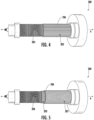
Fig. 3 is a schematic side perspective cut-away view of another embodiment of a fiber de-gassing membrane system for use in the fuel deoxygenation system ofFig. 1 , showing reinforcing fibers arranged separately from membrane fibers at an angle α relative to the longitudinal axis along a winding spool; -
Fig. 4 is a schematic side perspective cut-away view of another embodiment of a fiber de-gassing membrane system for use in the fuel deoxygenation system ofFig. 1 , showing reinforcing fibers arranged separately from the membrane fibers parallel to the longitudinal axis of the membrane system; and -
Fig. 5 is a schematic side perspective cut-away view of another embodiment of a fiber de-gassing membrane system for use in the fuel deoxygenation system ofFig. 1 , showing reinforcing fibers arranged separately from the membrane fibers substantially orthogonal to the longitudinal axis of the membrane system. - Reference will now be made to the drawings wherein like reference numerals identify similar structural features or aspects of the subject disclosure. For purposes of explanation and illustration, and not limitation, a schematic view of an exemplary embodiment of the fiber de-gassing membrane system with reinforcing fibers positioned within a fuel deoxygenation systems is shown in
Fig. 1 and is designated generally byreference character 100. Other embodiments of the fiber de-gassing membrane system in accordance with the disclosure, or aspects thereof, are provided inFigs. 2A-5 as will be described. The systems and methods described herein can be used to provide stress reduction in the fiber axial direction the absorbent interwoven membrane fibers in their axial directions, of a membrane in a fuel de-oxygenation system. Non-membrane reinforcement fibers are introduced to a membrane and help to relieve the load in the absorbent membrane fibers. By subjecting the absorbent membrane fibers to less stress, fuel leakage through the membrane is minimized. - As shown in
Figs. 1-2B , afuel deoxygenation system 10 includes a fiberde-gassing membrane system 100. Fiberde-gassing membrane system 100 includes a combination ofmembrane fibers 104. Themembrane system 100 includes reinforcingfibers 106. Reinforcingfibers 106 are positioned adjacent to themembrane fibers 104. Reinforcingfibers 106 are interwoven with themembrane fibers 104 parallel tomembrane fibers 104. Eachmembrane fiber 104 defines a longitudinal membrane fiber axis M. Eachmembrane fiber 104 has a first stiffness in a direction aligned with its longitudinal membrane fiber axis. Each reinforcingfiber 106 defines a longitudinal reinforcing fiber axis R. The reinforcingfibers 106 have a second stiffness in a direction aligned with its longitudinal reinforcing fiber axis. The second stiffness is greater than the first stiffness. The reinforcingfibers 106 are configured and adapted to provide re-distribution of local stresses in the direction of respective longitudinal membrane fiber axes between parallelly-arrangedmembrane fibers 104. This re-distribution is aimed to reduce local stresses in membrane fibers in the membrane fiber axial direction, i.e., reduce risk of their damage and associated probability of fuel leakage. Reinforcingfibers 106 are generally impermeable and therefore do not perform membrane functions but help to relieve axial load inmembrane fibers 104. - With continued reference to
Figs. 1-2B , it is contemplated that reinforcingfibers 106 include a carbon fiber, a glass fiber, an organic fiber (e.g., Kevlar) material, and/or any other suitable material in a variety of combinations. In some embodiments, the reinforcingfibers 106 include an impregnated polymeric matrix (e.g., thermoplastics, thermosets, elastomers, etc.). Themembrane fibers 104 can include a polymeric matrix withhollow fiber body 111 with covered withcoating 109. The polymeric matrix can be the same as the impregnated polymeric matrix in reinforcingfibers 106 or different. - The addition of reinforcing
fibers 106 offers a low-cost option to enhance durability ofmembrane fibers 104 by reducing membrane micro-damage tocoating 109, thereby and improving leakage resistance. Those skilled in the art will readily appreciate that interweaving non-membrane "parasitic" tension elements with high stiffness withmembrane fibers 104, results in a significant re-distribution of local stresses between parallelly-arranged membrane and non-membrane fibers, 104 and 106 respectively. In this case, membrane fibers are much less loaded, i.e., have significantly lower risk of micro-damage. - As shown in
Fig. 3 , another embodiment of a fiberde-gassing membrane system 200 includes a plurality ofmembrane fibers 204. In the embodiment ofFig. 3 ,membrane fibers 204 form at least onelayer 202 that can be interwoven with other layers.Membrane system 200 includes reinforcingfibers 206. Orientation of reinforcingfibers 206 with respect to the longitudinal orientation of the membrane system is defined by angle +α (or - α in the antisymmetric direction).Membrane system 200 is similar tomembrane system 100, except that instead of showing reinforcingfibers 206 withmembrane fibers 204 in a common layer, or interwoven withmembrane fibers 204, they make up their own layer 201. It is also contemplated that the interwoven layers ofmembrane system 100 could be combined with the individual layers 201 of reinforcingfibers 206 ofmembrane system 200 into the same membrane. In the reinforcing layer 201, the reinforcingfibers 206 are arranged at an angle α relative to longitudinal axis A of themembrane system 200. Angle α between the reinforcingfibers 206 and the longitudinal axis is greater than 20 degrees and less than 75 degrees. Similarly, this angle α between the reinforcingfibers 206 and the longitudinal axis A can be less than -20 degrees and greater than -75 degrees. - With reference now to
Fig. 4 ,membrane system 200 is the same asmembrane system 200 ofFig. 3 . In the embodiment ofFig. 4 , reinforcingfibers 206 are arranged in an axial direction, extending from one end of themembrane system 200 to the other.Fibers 206 are shown grouped into alayer 203 of reinforcingfibers 206, however those skilled in the art will readily appreciate that reinforcingfibers 206 can be interwoven withmembrane fibers 204 as well. In all of the embodiments forFigs. 3-5 , themembrane fibers 204 have a first stiffness in a membrane fiber axis direction and the reinforcingfibers 206 have a second stiffness in a reinforcing fiber axis direction. The second stiffness is greater than the first stiffness. The reinforcingfibers 206 can be radially inward or radially outward frommembrane fibers 204. In the embodiment ofFig. 4 , the angle α is an absolute angle 15 degrees or less relative to the longitudinal axis. Similarly, this angle α can be an absolute angle -15 degrees or greater relative to the longitudinal axis. - As shown in
Fig. 5 ,membrane system 200 is the same asmembrane system 100 ofFig. 3 , except that reinforcingfibers 206 are arranged at an angle α relative to longitudinal axis A of the membrane that is in the hoop direction, e.g., substantially circumferential. InFig. 5 , the reinforcingfibers 206 are shown grouped together in a reinforcinglayer 205 InFig. 5 , the angle α is an absolute angle 80 degrees or more relative to the longitudinal axis. Similarly, angle α is an absolute angle -80 degrees or less relative to the longitudinal axis. Similar to above, themembrane fibers 204 have a first stiffness in their longitudinal membrane fiber axis direction and reinforcingfibers 206 have a second stiffness in their longitudinal reinforcing fiber axis direction. The second stiffness is greater than the first stiffness. - With continued reference to
Fig. 5 , it is also contemplated that axially arranged reinforcingfibers 206, like those ofFig. 4 , can be used in thesame membrane system 200 as reinforcingfibers 206 arranged in the hoop direction, like those ofFig. 5 , and/or reinforcingfibers 206 oflayer 202 ofFig. 3 . In conventional membrane layups, the membrane fibers are mainly two-directional, i.e., as +α and -α, where a is typically close to 45 deg. In the case of non-ideal implementations or conditions (imperfections, misalignments, statistical variation, non-uniformity through thickness, etc.) two-directional layups can be associated with considerable local overload due to limited ability of individual fibers to handle stresses other than axial ones. By adding reinforcingfibers 206 in the hoop direction, axial direction, parallel to existing membrane layers, or in some combination, in addition to [+α/- α] layers 102 ofFigs. 1-2B , local overload can be reduced. - A method of assembling a fiber de-gassing membrane, e.g.,
membrane system membrane fibers spool 20. Each membrane fiber defines a longitudinal membrane fiber axis. At least one of the membrane fibers has a first stiffness in a direction aligned with its longitudinal membrane fiber axis. The method includes adding reinforcing fibers, e.g., reinforcingfibers - The methods and systems of the present disclosure, as described above and shown in the drawings, provide for low-cost systems and methods for reducing stress on membrane fibers, thereby reducing fuel leakage, with superior properties including improved reliability and product quality. While the apparatus and methods of the subject disclosure have been shown and described with reference to preferred embodiments, those skilled in the art will readily appreciate that changes and/or modifications may be made thereto without departing from the scope of the invention as defined by the claims.
Claims (15)
- A fiber de-gassing membrane system, the system comprising:a plurality of membrane fibers (104, 204) each defining a longitudinal membrane fiber axis, wherein at least one of the membrane fibers has a first stiffness in a longitudinal membrane fiber axis direction; andreinforcing fibers (106, 206) positioned adjacent to at least one of the plurality of membrane fibers, wherein the reinforcement fibers each define a longitudinal reinforcing fiber axis, wherein at least one of the reinforcing fibers has a second stiffness in a longitudinal reinforcing fiber axis direction, wherein the second stiffness is greater than the first stiffness.
- The membrane as recited in claim 1, wherein the reinforcing fibers (206) include at least one of a carbon, glass, or organic material.
- The membrane as recited in claim 1, wherein the reinforcing fibers (206) include an impregnated polymeric matrix.
- The membrane as recited in claim 3, wherein the polymeric matrix is a first polymeric matrix, and wherein the membrane fibers include a second polymeric matrix, wherein the second polymeric matrix is the same as the first polymeric matrix.
- The membrane as recited in any preceding claim, wherein at least one of the reinforcing fibers (206) is abutting at least one of the plurality of membrane fibers (204).
- The membrane as recited in claim 5, wherein at least one of the reinforcing fibers is positioned parallel to at least one of the plurality of membrane fibers.
- The membrane as recited in claim 5, wherein the at least one reinforcing fiber is configured and adapted to provide reduction of local axial stresses in the at least one membrane fiber arranged parallel to the at least one reinforcing fiber.
- The membrane as recited in any preceding claim 1, wherein at least one of the reinforcing fibers is positioned parallel to a longitudinal axis of the membrane system, and/or wherein at least one of the reinforcing fibers is positioned at an angle relative to a longitudinal axis of the membrane system, wherein the angle is at least one of an absolute angle 80 degrees or more relative to the longitudinal axis, or is an absolute angle -80 degrees or less relative to the longitudinal axis.
- The membrane as recited in any of claims 1 to 7, wherein at least one of the reinforcing fibers is positioned parallel to a longitudinal axis of the membrane system, radially outward from the plurality of membrane fibers and/or wherein at least one of the reinforcing fibers is positioned parallel to a longitudinal axis of the membrane system, radially inward from the plurality of membrane fibers.
- The membrane as recited in any preceding claim, wherein at least one of the reinforcing fibers is spirally wrapped radially outward from the plurality of membrane fibers, and/or wherein at least one of the reinforcing fibers is spirally wrapped radially inward from the plurality of membrane fibers.
- The membrane as recited in any preceding claim, wherein at least one of the reinforcing fibers is arranged at an angle relative to a longitudinal axis of the membrane system, wherein the angle is an absolute angle at least one of 15 degrees or less relative to the longitudinal axis, or - 15 degrees or more relative to the longitudinal axis, and optionally wherein an angle between at least one of the reinforcing fibers and the longitudinal axis of the membrane system is at least one of greater than 20 degrees and less than 75 degrees, or less than -20 degrees and greater than -75 degrees.
- A method of assembling a fiber de-gassing membrane system, the method comprising:winding a plurality of membrane fibers, wherein at least one of the membrane fibers has a first stiffness in a longitudinal membrane fiber axis direction; andadding reinforcing fibers adjacent to at least one of the plurality of membrane fibers,wherein the reinforcing fibers have a second stiffness in a longitudinal reinforcing fiber axis direction, wherein the second stiffness is greater than the first stiffness.
- The method as recited in claim 12, wherein adding the reinforcing fibers includes winding at least one of the reinforcing fibers adjacent to at least one of the plurality of membrane fibers concurrently with winding the plurality of membrane fibers.
- The method as recited in claim 13, wherein winding at least one of the reinforcing fibers includes winding at least one of the reinforcing fibers parallel to at least one of the plurality of membrane fibers.
- The membrane as recited in claim 12, wherein adding the reinforcing fibers includes positioning at least one of the reinforcing fibers in at least one of a circumferential direction or an axial direction in a reinforcing layer at least one of radially inward or radially outward from the plurality of membrane fibers.
Applications Claiming Priority (1)
| Application Number | Priority Date | Filing Date | Title |
|---|---|---|---|
| US17/735,118 US12594510B2 (en) | 2022-05-03 | 2022-05-03 | Reinforced membrane systems |
Publications (1)
| Publication Number | Publication Date |
|---|---|
| EP4272857A1 true EP4272857A1 (en) | 2023-11-08 |
Family
ID=86328968
Family Applications (1)
| Application Number | Title | Priority Date | Filing Date |
|---|---|---|---|
| EP23171409.8A Pending EP4272857A1 (en) | 2022-05-03 | 2023-05-03 | Reinforced membrane systems |
Country Status (2)
| Country | Link |
|---|---|
| US (1) | US12594510B2 (en) |
| EP (1) | EP4272857A1 (en) |
Citations (6)
| Publication number | Priority date | Publication date | Assignee | Title |
|---|---|---|---|---|
| US4293418A (en) * | 1979-03-28 | 1981-10-06 | Toray Industries, Inc. | Fluid separation apparatus |
| JP2001334131A (en) * | 2000-05-25 | 2001-12-04 | Nok Corp | Hollow fiber membrane, processing method of hollow fiber membrane, hollow fiber membrane module, use of hollow fiber membrane module and manufacturing method of hollow fiber membrane module |
| US20120174790A1 (en) * | 2009-08-21 | 2012-07-12 | Toray Industries, Inc. | Water-vapor-permeable membrane, hollow-fiber membrane, and hollow-fiber membrane module |
| CN202638297U (en) * | 2012-05-15 | 2013-01-02 | 北京碧水源膜科技有限公司 | Composite reinforced hollow fiber membrane |
| US20160009578A1 (en) * | 2013-02-22 | 2016-01-14 | General Electric Company | Membrane assembly for supporting a biofilm |
| CN107585865A (en) * | 2017-11-02 | 2018-01-16 | 安徽华骐环保科技股份有限公司 | A kind of new microbubble is oxygenated biological film wire and method for treating water |
Family Cites Families (16)
| Publication number | Priority date | Publication date | Assignee | Title |
|---|---|---|---|---|
| US4631128A (en) * | 1978-09-19 | 1986-12-23 | Albany International Corporation | Permselective hollow fiber bundle |
| JPH0647212B2 (en) | 1987-08-10 | 1994-06-22 | 日立湘南電子株式会社 | Press-fitting mechanism |
| WO1998028065A1 (en) | 1996-12-24 | 1998-07-02 | Kitz Corporation | Hollow-fiber membrane module and process for the production thereof |
| EP1174175B1 (en) | 1999-04-02 | 2008-02-20 | Mitsubishi Rayon Co., Ltd. | Potting agent for a hollow fiber membrane module, hollow fiber membrane module and uses of said hollow fiber membrane module |
| JP2002166141A (en) * | 2000-09-21 | 2002-06-11 | Mitsubishi Rayon Co Ltd | Porous membrane |
| US8070859B2 (en) | 2004-02-25 | 2011-12-06 | Membrane Technology And Research, Inc. | Method for producing a non-porous membrane |
| US7422813B2 (en) * | 2004-06-08 | 2008-09-09 | Microcell Corporation | Fuel cell systems comprising microfibrous fuel cell elements and methods of making and using same |
| US9132390B2 (en) * | 2009-03-26 | 2015-09-15 | Bl Technologies Inc. | Non-braided reinforced holow fibre membrane |
| JP5772867B2 (en) * | 2013-04-23 | 2015-09-02 | Nok株式会社 | Fiber reinforced porous hollow fiber membrane |
| JP5999262B2 (en) * | 2014-04-03 | 2016-09-28 | 三菱レイヨン株式会社 | Hollow fiber membrane sheet laminate, method for producing hollow fiber membrane sheet laminate, hollow fiber membrane module, and method for producing hollow fiber membrane module |
| CN104815563A (en) | 2015-04-20 | 2015-08-05 | 天津工业大学 | Reinforced hollow fibrous membrane and preparation method thereof |
| CN204977622U (en) * | 2015-04-26 | 2016-01-20 | 钟增元 | Comfortable function surface fabric of elasticity |
| CN109070005A (en) * | 2016-05-11 | 2018-12-21 | 三菱化学可菱水株式会社 | Hollow fiber film assembly |
| EP3508233B1 (en) * | 2016-08-31 | 2023-03-01 | Terumo Kabushiki Kaisha | Heat exchanger, artificial lung, and method of manufacturing heat exchanger |
| TR201915068A2 (en) * | 2019-10-02 | 2021-04-21 | Univ Istanbul Teknik | AQUAPORIN Z DOUBLE MEMBRANE PRODUCTION METHOD |
| CN211936379U (en) * | 2020-01-15 | 2020-11-17 | 山东工业陶瓷研究设计院有限公司 | A denitrification and dust removal integrated ceramic membrane device |
-
2022
- 2022-05-03 US US17/735,118 patent/US12594510B2/en active Active
-
2023
- 2023-05-03 EP EP23171409.8A patent/EP4272857A1/en active Pending
Patent Citations (6)
| Publication number | Priority date | Publication date | Assignee | Title |
|---|---|---|---|---|
| US4293418A (en) * | 1979-03-28 | 1981-10-06 | Toray Industries, Inc. | Fluid separation apparatus |
| JP2001334131A (en) * | 2000-05-25 | 2001-12-04 | Nok Corp | Hollow fiber membrane, processing method of hollow fiber membrane, hollow fiber membrane module, use of hollow fiber membrane module and manufacturing method of hollow fiber membrane module |
| US20120174790A1 (en) * | 2009-08-21 | 2012-07-12 | Toray Industries, Inc. | Water-vapor-permeable membrane, hollow-fiber membrane, and hollow-fiber membrane module |
| CN202638297U (en) * | 2012-05-15 | 2013-01-02 | 北京碧水源膜科技有限公司 | Composite reinforced hollow fiber membrane |
| US20160009578A1 (en) * | 2013-02-22 | 2016-01-14 | General Electric Company | Membrane assembly for supporting a biofilm |
| CN107585865A (en) * | 2017-11-02 | 2018-01-16 | 安徽华骐环保科技股份有限公司 | A kind of new microbubble is oxygenated biological film wire and method for treating water |
Also Published As
| Publication number | Publication date |
|---|---|
| US12594510B2 (en) | 2026-04-07 |
| US20230356112A1 (en) | 2023-11-09 |
Similar Documents
| Publication | Publication Date | Title |
|---|---|---|
| EP2581638B1 (en) | High-pressure tank and manufacturing method of high pressure tank. | |
| JP3735113B2 (en) | Pipe and manufacturing method thereof | |
| US10168002B2 (en) | Breather layer for exhausting permeate from pressure vessels | |
| US4699288A (en) | High pressure vessel construction | |
| US8679606B2 (en) | Thick walled composite tubular and method of making | |
| US5693166A (en) | Method for fabricating a high-damping rib-stiffened composite hollow cylinder core configuration | |
| US3293860A (en) | Filament wound container having reinforced opening | |
| US11597166B2 (en) | Method of manufacturing high-pressure tank | |
| US5415079A (en) | Composite cylinder for use in aircraft hydraulic actuator | |
| US20090314785A1 (en) | Damage and leakage barrier in all-composite pressure vessels and storage tanks | |
| WO2016020972A1 (en) | High-pressure tank and manufacturing method for high-pressure tank | |
| JP7223802B2 (en) | High pressure tank and its manufacturing method | |
| EP3075524B1 (en) | Pressure bulkhead and method for producing a pressure bulkhead | |
| US20220065400A1 (en) | Tank production method and tank | |
| US20180163772A1 (en) | Composite shaft arrangement with load introduction elements | |
| US12594510B2 (en) | Reinforced membrane systems | |
| JP7230758B2 (en) | Constraint structure of structure | |
| JPH06286014A (en) | Method for manufacturing flexible fluid transport pipe | |
| JP7761620B2 (en) | Tank and tank manufacturing method | |
| KR102925289B1 (en) | High pressure container with boss reinforced winding and menufacturing method thereof | |
| JPH05229018A (en) | Production of cylindrical laminate due to filament winding molding method | |
| JP2006519961A5 (en) | ||
| US20200215773A1 (en) | Hybrid metallic/composite arrangement for torque, bending, shear, and axial loading | |
| US20250067301A1 (en) | Composite drive shafts | |
| JP6266293B2 (en) | Pressure vessel and method for manufacturing the same |
Legal Events
| Date | Code | Title | Description |
|---|---|---|---|
| PUAI | Public reference made under article 153(3) epc to a published international application that has entered the european phase |
Free format text: ORIGINAL CODE: 0009012 |
|
| STAA | Information on the status of an ep patent application or granted ep patent |
Free format text: STATUS: THE APPLICATION HAS BEEN PUBLISHED |
|
| AK | Designated contracting states |
Kind code of ref document: A1 Designated state(s): AL AT BE BG CH CY CZ DE DK EE ES FI FR GB GR HR HU IE IS IT LI LT LU LV MC ME MK MT NL NO PL PT RO RS SE SI SK SM TR |
|
| RIN1 | Information on inventor provided before grant (corrected) |
Inventor name: LOKHANDWALLA, MURTUZA Inventor name: CORDATOS, HARALAMBOS Inventor name: HUNTER, ALAN Inventor name: CALDECUTT, ANDREW M. Inventor name: STONER, REBECCA R Inventor name: KOKAS, JAY W Inventor name: GURVICH, MARK |
|
| STAA | Information on the status of an ep patent application or granted ep patent |
Free format text: STATUS: REQUEST FOR EXAMINATION WAS MADE |
|
| 17P | Request for examination filed |
Effective date: 20240507 |
|
| RBV | Designated contracting states (corrected) |
Designated state(s): AL AT BE BG CH CY CZ DE DK EE ES FI FR GB GR HR HU IE IS IT LI LT LU LV MC ME MK MT NL NO PL PT RO RS SE SI SK SM TR |
|
| STAA | Information on the status of an ep patent application or granted ep patent |
Free format text: STATUS: EXAMINATION IS IN PROGRESS |
|
| 17Q | First examination report despatched |
Effective date: 20241125 |