EP4271260B1 - An apparatus and a method for measuring flow resistances of blood vessels - Google Patents
An apparatus and a method for measuring flow resistances of blood vessels Download PDFInfo
- Publication number
- EP4271260B1 EP4271260B1 EP22715119.8A EP22715119A EP4271260B1 EP 4271260 B1 EP4271260 B1 EP 4271260B1 EP 22715119 A EP22715119 A EP 22715119A EP 4271260 B1 EP4271260 B1 EP 4271260B1
- Authority
- EP
- European Patent Office
- Prior art keywords
- blood vessels
- wavelength
- wavelengths
- specific component
- electromagnetic radiation
- Prior art date
- Legal status (The legal status is an assumption and is not a legal conclusion. Google has not performed a legal analysis and makes no representation as to the accuracy of the status listed.)
- Active
Links
Images




Classifications
-
- A—HUMAN NECESSITIES
- A61—MEDICAL OR VETERINARY SCIENCE; HYGIENE
- A61B—DIAGNOSIS; SURGERY; IDENTIFICATION
- A61B5/00—Measuring for diagnostic purposes; Identification of persons
- A61B5/02—Detecting, measuring or recording for evaluating the cardiovascular system, e.g. pulse, heart rate, blood pressure or blood flow
- A61B5/026—Measuring blood flow
- A61B5/0261—Measuring blood flow using optical means, e.g. infrared light
-
- A—HUMAN NECESSITIES
- A61—MEDICAL OR VETERINARY SCIENCE; HYGIENE
- A61B—DIAGNOSIS; SURGERY; IDENTIFICATION
- A61B5/00—Measuring for diagnostic purposes; Identification of persons
- A61B5/02—Detecting, measuring or recording for evaluating the cardiovascular system, e.g. pulse, heart rate, blood pressure or blood flow
- A61B5/02007—Evaluating blood vessel condition, e.g. elasticity, compliance
-
- A—HUMAN NECESSITIES
- A61—MEDICAL OR VETERINARY SCIENCE; HYGIENE
- A61B—DIAGNOSIS; SURGERY; IDENTIFICATION
- A61B5/00—Measuring for diagnostic purposes; Identification of persons
- A61B5/02—Detecting, measuring or recording for evaluating the cardiovascular system, e.g. pulse, heart rate, blood pressure or blood flow
- A61B5/021—Measuring pressure in heart or blood vessels
- A61B5/022—Measuring pressure in heart or blood vessels by applying pressure to close blood vessels, e.g. against the skin; Ophthalmodynamometers
-
- A—HUMAN NECESSITIES
- A61—MEDICAL OR VETERINARY SCIENCE; HYGIENE
- A61B—DIAGNOSIS; SURGERY; IDENTIFICATION
- A61B5/00—Measuring for diagnostic purposes; Identification of persons
- A61B5/02—Detecting, measuring or recording for evaluating the cardiovascular system, e.g. pulse, heart rate, blood pressure or blood flow
- A61B5/021—Measuring pressure in heart or blood vessels
- A61B5/022—Measuring pressure in heart or blood vessels by applying pressure to close blood vessels, e.g. against the skin; Ophthalmodynamometers
- A61B5/02233—Occluders specially adapted therefor
-
- A—HUMAN NECESSITIES
- A61—MEDICAL OR VETERINARY SCIENCE; HYGIENE
- A61B—DIAGNOSIS; SURGERY; IDENTIFICATION
- A61B5/00—Measuring for diagnostic purposes; Identification of persons
- A61B5/02—Detecting, measuring or recording for evaluating the cardiovascular system, e.g. pulse, heart rate, blood pressure or blood flow
- A61B5/021—Measuring pressure in heart or blood vessels
- A61B5/022—Measuring pressure in heart or blood vessels by applying pressure to close blood vessels, e.g. against the skin; Ophthalmodynamometers
- A61B5/02233—Occluders specially adapted therefor
- A61B5/02241—Occluders specially adapted therefor of small dimensions, e.g. adapted to fingers
-
- A—HUMAN NECESSITIES
- A61—MEDICAL OR VETERINARY SCIENCE; HYGIENE
- A61B—DIAGNOSIS; SURGERY; IDENTIFICATION
- A61B5/00—Measuring for diagnostic purposes; Identification of persons
- A61B5/02—Detecting, measuring or recording for evaluating the cardiovascular system, e.g. pulse, heart rate, blood pressure or blood flow
- A61B5/021—Measuring pressure in heart or blood vessels
- A61B5/022—Measuring pressure in heart or blood vessels by applying pressure to close blood vessels, e.g. against the skin; Ophthalmodynamometers
- A61B5/0225—Measuring pressure in heart or blood vessels by applying pressure to close blood vessels, e.g. against the skin; Ophthalmodynamometers the pressure being controlled by electric signals, e.g. derived from Korotkoff sounds
- A61B5/02255—Measuring pressure in heart or blood vessels by applying pressure to close blood vessels, e.g. against the skin; Ophthalmodynamometers the pressure being controlled by electric signals, e.g. derived from Korotkoff sounds the pressure being controlled by plethysmographic signals, e.g. derived from optical sensors
-
- A—HUMAN NECESSITIES
- A61—MEDICAL OR VETERINARY SCIENCE; HYGIENE
- A61B—DIAGNOSIS; SURGERY; IDENTIFICATION
- A61B5/00—Measuring for diagnostic purposes; Identification of persons
- A61B5/145—Measuring characteristics of blood in vivo, e.g. gas concentration or pH-value ; Measuring characteristics of body fluids or tissues, e.g. interstitial fluid or cerebral tissue
- A61B5/1455—Measuring characteristics of blood in vivo, e.g. gas concentration or pH-value ; Measuring characteristics of body fluids or tissues, e.g. interstitial fluid or cerebral tissue using optical sensors, e.g. spectral photometrical oximeters
-
- A—HUMAN NECESSITIES
- A61—MEDICAL OR VETERINARY SCIENCE; HYGIENE
- A61B—DIAGNOSIS; SURGERY; IDENTIFICATION
- A61B5/00—Measuring for diagnostic purposes; Identification of persons
- A61B5/68—Arrangements of detecting, measuring or recording means, e.g. sensors, in relation to patient
- A61B5/6801—Arrangements of detecting, measuring or recording means, e.g. sensors, in relation to patient specially adapted to be attached to or worn on the body surface
- A61B5/6813—Specially adapted to be attached to a specific body part
- A61B5/6825—Hand
- A61B5/6826—Finger
-
- A—HUMAN NECESSITIES
- A61—MEDICAL OR VETERINARY SCIENCE; HYGIENE
- A61B—DIAGNOSIS; SURGERY; IDENTIFICATION
- A61B5/00—Measuring for diagnostic purposes; Identification of persons
- A61B5/68—Arrangements of detecting, measuring or recording means, e.g. sensors, in relation to patient
- A61B5/6801—Arrangements of detecting, measuring or recording means, e.g. sensors, in relation to patient specially adapted to be attached to or worn on the body surface
- A61B5/6843—Monitoring or controlling sensor contact pressure
-
- G—PHYSICS
- G16—INFORMATION AND COMMUNICATION TECHNOLOGY [ICT] SPECIALLY ADAPTED FOR SPECIFIC APPLICATION FIELDS
- G16H—HEALTHCARE INFORMATICS, i.e. INFORMATION AND COMMUNICATION TECHNOLOGY [ICT] SPECIALLY ADAPTED FOR THE HANDLING OR PROCESSING OF MEDICAL OR HEALTHCARE DATA
- G16H40/00—ICT specially adapted for the management or administration of healthcare resources or facilities; ICT specially adapted for the management or operation of medical equipment or devices
- G16H40/60—ICT specially adapted for the management or administration of healthcare resources or facilities; ICT specially adapted for the management or operation of medical equipment or devices for the operation of medical equipment or devices
- G16H40/63—ICT specially adapted for the management or administration of healthcare resources or facilities; ICT specially adapted for the management or operation of medical equipment or devices for the operation of medical equipment or devices for local operation
-
- G—PHYSICS
- G16—INFORMATION AND COMMUNICATION TECHNOLOGY [ICT] SPECIALLY ADAPTED FOR SPECIFIC APPLICATION FIELDS
- G16H—HEALTHCARE INFORMATICS, i.e. INFORMATION AND COMMUNICATION TECHNOLOGY [ICT] SPECIALLY ADAPTED FOR THE HANDLING OR PROCESSING OF MEDICAL OR HEALTHCARE DATA
- G16H50/00—ICT specially adapted for medical diagnosis, medical simulation or medical data mining; ICT specially adapted for detecting, monitoring or modelling epidemics or pandemics
- G16H50/30—ICT specially adapted for medical diagnosis, medical simulation or medical data mining; ICT specially adapted for detecting, monitoring or modelling epidemics or pandemics for calculating health indices; for individual health risk assessment
-
- A—HUMAN NECESSITIES
- A61—MEDICAL OR VETERINARY SCIENCE; HYGIENE
- A61B—DIAGNOSIS; SURGERY; IDENTIFICATION
- A61B5/00—Measuring for diagnostic purposes; Identification of persons
- A61B5/02—Detecting, measuring or recording for evaluating the cardiovascular system, e.g. pulse, heart rate, blood pressure or blood flow
- A61B5/024—Measuring pulse rate or heart rate
- A61B5/02416—Measuring pulse rate or heart rate using photoplethysmograph signals, e.g. generated by infrared radiation
Definitions
- the disclosure relates to an apparatus and a method for measuring flow resistances of blood vessels. Furthermore, the disclosure relates to a computer program for measuring flow resistances of blood vessels.
- vascular pathology and its progression involves measurement and estimation of different quantitative measures such as for example: blood pressure, a blood vessel cross sectional area, a blood vessel mean diameter, blood vessel stiffness, and blood vessel flow resistance.
- abnormal blood vessel stiffness and flow resistance are associated with an increased risk of cardiovascular events such as myocardial infarction and stroke, which are two leading causes of death in the developed world.
- An increase in arterial stiffness and flow resistance may increase the load of the heart, since the heart needs to perform more work to maintain a required blood flow volume. Over time, this increased workload may cause left ventricular hypertrophy and left ventricular remodelling, which can lead to a heart failure.
- the increased workload may also be associated with a higher heart rate, a proportionately longer duration of systole, and a reduction of duration of diastole. This decreases the amount of time available for perfusion of cardiac tissue, which mainly occurs during diastole.
- a hypertrophic heart which has a greater oxygen demand, may have a compromised supply of oxygen and nutrients.
- Multi-Wavelength Photoplethysmography Device for the Measurement of Pulse Transit Time in the Skin Microvasculature, Computing in Cardiology, 2020-09-16 describes a multiwavelength photoplethysmography "MWPPG" device for studying the skin microvasculature.
- the device utilizes the fact that the penetration depth of light into the skin is depended on the light wavelength. Thus, the device allows to study blood vessels at different depths.
- Publication US2017172430 describes a method for cuff-less blood pressure measurement.
- the method comprises recording a physiological signal and multi-wavelength photoplethysmography "PPG" signals from a predetermined body part, deriving the depth-specific PPG signal reflecting the arterial blood volume with the physiological signal as a reference, calculating the pulse transit time "PTT” from the physiological signal and the derived arterial blood PPG signal, and calculating the blood pressure from the calculated PTT and blood pressure relationship.
- PPG photoplethysmography
- US2019336016 describes a device for non-invasive capillary blood pressure measurement.
- the device comprises a front end in contact with a body to compress and decompress capillaries in tissue, a pressure control module for regulating contact pressure between the front end and the tissue, a pressure transducer coupled to the front end for measuring the contact pressure, a capillary sensing module for detecting capillary pulsations under the contact pressure modulation, and a computing system for running an algorithm to determine capillary pressure based on the capillary pulsations and the contact pressure modulation.
- An apparatus for measuring flow resistances of blood vessels comprises:
- the control system is configured to optimize resistance values of a circuit model to minimize differences between waveforms of node voltages of the circuit model and measured waveforms of blood pressures being in the blood vessels reflecting off different ones of the wavelengths, wherein capacitor values of the circuit model are based on the above-mentioned compliances of the blood vessels reflecting off the different wavelengths and the optimized resistance values are indicative of the flow resistances of the blood vessels reflecting off the different wavelengths.
- the above-mentioned pressure instrument can be for example a device for directing mechanical pressure to a fingertip or a toe, or a device comprising a cuff and a pump system for controlling gas pressure inside the cuff to direct mechanical pressure to an arm.
- the photoplethysmography "PPG" sensor can be configured to emit electromagnetic radiation having wavelength in the range from 625 nm to 1000 nm, i.e. red or infrared light, in order to measure the flow resistance of arteries located in the hypodermis, and electromagnetic radiation having wavelength in the range from 565 nm to 590 nm, i.e. yellow light, in order to measure the flow resistance of blood vessels located in an upper portion of the hypodermis, and electromagnetic radiation having wavelength in the range from 500 nm to 565 nm, i.e. green light, in order to measure the flow resistance of arterioles located in the dermis, and electromagnetic radiation having wavelength in the range from 450 nm to 485 nm, i.e. blue light, in order to measure the flow resistance of capillaries located in an upper portion of the dermis.
- electromagnetic radiation having wavelength in the range from 625 nm to 1000 nm, i.e. red or infrared light in order to measure the
- a method for measuring flow resistances of blood vessels comprises:
- a computer program for measuring flow resistances of blood vessels.
- a computer program according to the invention comprises computer executable instructions for controlling a programmable processing system to:
- a computer program product according to the invention comprises a nonvolatile computer readable medium, e.g. a compact disc "CD”, encoded with a computer program according to the invention.
- a computer program product comprises a nonvolatile computer readable medium, e.g. a compact disc "CD", encoded with a computer program according to the invention.
- FIG 1a shows a schematic illustration of an apparatus according to an exemplifying and non-limiting embodiment for measuring flow resistances of blood vessels.
- the apparatus comprises a photoplethysmography "PPG" sensor 101 for emitting, to a fingertip 108 of an individual, electromagnetic radiation and for receiving a part of the electromagnetic radiation reflected off the blood vessels of the fingertip 108.
- the PPG sensor 101 comprises a radiation emitter 106 and a photodetector 107.
- the radiation emitter 106 may comprises e.g. one or more light emitting diodes "LED” and the photodetector 107 may comprise e.g. one or more photodiodes or phototransistors.
- Figure 1a shows also a magnified, schematic section view 110 of the fingertip.
- the section plane is parallel with the yz-plane of a coordinate system 199.
- the PPG sensor 101 is configured to emit the electromagnetic radiation so that the electromagnetic radiation contains radiation components with five different wavelengths.
- the radiation components are depicted with polyline arrows 127, 128, 129, 130, and 131.
- the first radiation component 127 can be for example infrared radiation having a wavelength on the range from 700 nm to 1000 nm
- the second radiation component 128 can be for example red radiation having a wavelength on the range from 625 nm to 700 nm
- the third radiation component 129 can be for example yellow radiation having a wavelength on the range from 565 nm to 590 nm
- the fourth radiation component 130 can be for example green radiation having a wavelength on the range from 500 nm to 565 nm
- the fifth radiation component 131 can be for example blue radiation having a wavelength on the range from 450 nm to 485 nm.
- the first radiation component 127 can be infrared radiation having a wavelength on the range from 800 nm to 900 nm
- the second radiation component 128 can be red radiation having a wavelength on the range from 650 nm to 675 nm
- the third radiation component 129 can be yellow radiation having a wavelength on the range from 575 nm to 580 nm
- the fourth radiation component 130 can be green radiation having a wavelength on the range from 530 nm to 545 nm
- the fifth radiation component 131 can be blue radiation having a wavelength on the range from 460 nm to 475 nm.
- the red and infrared radiation components 127 and 128 reach arteries 111 located in the hypodermis 114
- the yellow radiation component 129 reach blood vessels located in a portion of the hypodermis 114 adjacent to the dermis 115
- the green radiation component 130 reach arterioles 112 located in the dermis 115
- the blue radiation component 131 reach capillaries 112 located in a portion of the dermis 115 adjacent to the epidermis 116. Therefore, shorter wavelengths are reflected off smaller blood vessels, i.e. blood vessels nearer to a skin surface, than longer wavelengths.
- the photodetector 107 of the PPG sensor 101 is configured produce a measurement signal that comprises wavelength-specific component signals indicative of received wavelengths reflected off the blood vessels.
- Figure 1b shows graphs illustrating exemplifying wavelength-specific component signals 117, 118, 119, 120, and 121 of an exemplifying measurement signal 122.
- the wavelength-specific component signal 117 corresponds to infrared radiation
- the wavelength-specific component signal 118 corresponds to red radiation
- the wavelength-specific component signal 119 corresponds to yellow radiation
- the wavelength-specific component signal 120 corresponds to green radiation
- the wavelength-specific component signal 121 corresponds to blue radiation.
- the photodetector 107 may comprise for example many photodiodes or phototransistors that are sensitive to different wavelengths, or the photodetector 107 may comprise filters to implement wavelength separation.
- the apparatus comprises a pressure instrument 102 configured to produce controllable mechanical pressure P applied on the blood vessels.
- the apparatus comprises a control system 103 configured to control the pressure instrument 102 to change, i.e. to decrease or increase, the mechanical pressure linearly with respect to time t when the electromagnetic radiation is emitted to the blood vessels and a reflected part of the electromagnetic radiation is received from the blood vessels.
- Figure 1b shows a line 132 illustrating the time dependence of the mechanical pressure in the exemplifying situation in which the mechanical pressure has been linearly decreased and the above-mentioned wavelength-specific component signals 117-121 have been measured.
- the pressure instrument 102 comprises a pressure sensor 109 for measuring the mechanical pressure P directed by the fingertip 108 to the pressure sensor 108 and pressing means for controllably pressing the fingertip 108 against the PPG sensor 101 and the pressure sensor 109.
- the pressing means comprise a pressing element 105 and a force generator 104 for directing force to the pressing element 105.
- the force generator 104 may comprise for example an electric stepper motor and a threaded rod or some other suitable elements for generating force.
- the control system 103 is configured to find, from each of the wavelength-specific component signals 117-121, a portion whose envelope has exponential change, i.e. exponential growth or exponential decrease, with respect to time when the mechanical pressure decreases linearly with respect to time.
- the control system 103 is configured to produce, for each of the wavelength-specific component signals 117-121, an estimate for a coefficient of time related to the above-mentioned exponential change.
- the coefficient of time is indicative of the compliance of the blood vessels reflecting off the wavelength corresponding to the wavelength-specific component signal under consideration and thereby also the stiffness of these blood vessels.
- each of the wavelength-specific component signals 117-121 has a portion whose envelope has exponential growth.
- Figure 1b shows a magnification of a part of the wavelength-specific component signal 119.
- the envelopes of the wavelength-specific component signals 117-121 are depicted with thick lines.
- the exponential growth ⁇ e ⁇ Yt on a part of the envelope of the wavelength-specific component signal 119 is depicted with a dashed line.
- the coefficient of time related to the exponential growth is ⁇ Y .
- the coefficient of time ⁇ Y is indicative of the compliance of the blood vessels from which yellow light is reflected off and thereby also the stiffness of the blood vessels from which the yellow light is reflected off.
- control system 103 is configured to convert the wavelength-specific components 117-121 of the measurement signal to a logarithmic scale.
- Figure 1c shows graphs illustrating the converted wavelength-specific component signals 117', 118', 119', 120', and 121' which corresponds to the wavelength-specific component signals 117, 118, 119, 120, and 121 shown in figure 1b , respectively. Due to the logarithmic conversion, the exponential change is converted into linear change that is depicted with lines 117", 118", 119", 120", and 121" shown in figure 1c .
- the control system 103 is configured to estimate the slope of the linear change of the envelope of each converted wavelength-specific component signal. The slope is the coefficient of time related to the exponential change. In the exemplifying case shown in figures 1b and 1c , the slope i.e.
- ⁇ IR the coefficient of time related to the infrared light
- ⁇ R the coefficient of time related to the red light
- ⁇ Y the coefficient of time related to the yellow light
- ⁇ G the coefficient of time related to the green light
- ⁇ B the coefficient of time related to the blue light
- ⁇ R is the indicative of compliance of arteries and thereby also the stiffness of the arteries
- ⁇ G is indicative of compliance of arterioles and thereby also the stiffness of the arterioles
- the control system 103 is configured to optimize resistance values of a circuit model to minimize differences between waveforms of node voltages of the circuit model and measured waveforms of blood pressures prevailing in the blood vessels reflecting off different ones of the wavelengths. Capacitor values of the circuit model are based on the above-mentioned compliances of the blood vessels, and the optimized resistance values are indicative of the flow resistances of the blood vessels.
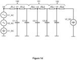
- Figure 1d shows an exemplifying circuit model used for estimating the flow resistances of blood vessels. In this exemplifying case, the circuit model comprises three circuit segments 150, 151, and 152.
- the circuit segment 150 may model for example arteries located in the hypodermis, the circuit segment 151 may model for example arterioles located in the dermis, and the circuit segment 152 may model for example capillaries located in an upper portion of the dermis.
- Node voltage U1 can model the blood pressure prevailing in the blood vessels reflecting off infrared and red light
- node voltage U2 can model the blood pressure prevailing in the blood vessels reflecting off green light
- node voltage U3 can model the blood pressure prevailing in the blood vessels reflecting off blue light.
- Node voltage U0 can have a waveform whose maximum is measured systolic blood pressure and whose minimum is measured diastolic blood pressure. The shape of the waveform of the node voltage U0 can be modelled e.g.
- V1_AC + V2_AC + V1_DC V1_AC + V2_AC + V1_DC
- V1_AC V1sin(2 ⁇ ⁇ HR/60 ⁇ t)
- V2_AC V2sin(2 ⁇ ⁇ 2HR/60 ⁇ t)
- HR is a heart rate as heart beats per minute
- V1, V2, and V1_DC are selected so that the maximum of U0 is the measured systolic blood pressure and the minimum of U0 is the measured diastolic blood pressure.
- Voltage levels in the circuit model are advantageously selected so that volts correspond directly to millimeters of mercury "mmHg".
- V1_DC from 80 to 120 volts, e.g. 100 volts.
- the peak-to-peak of U0 is from 25 to 40 volts e.g. about 35 V.
- Voltage V2_DC models the blood pressure after the capillaries and it can be on the range from 0 to 10 volts, or on the range from 3 to 8 volts.
- the capacitor values of the circuit model are based on the above-mentioned compliances of the blood vessels.
- the above-described way to model the input voltage U0 of the circuit model is an example only. It is also possible to measure or estimate a waveform of blood pressure at the beginning of the greatest blood vessels, e.g. arteries, modelled by the circuit model and thereafter use the measured or estimated blood pressure waveform as the input voltage U0 of the circuit model. Furthermore, characteristic values e.g. amplitudes and phases of different sinusoidal AC components and a DC component of the input voltage U0 can be optimized parameters along with the resistance values of the circuit model. Furthermore, instantaneous values forming the waveform the input voltage U0 can be optimized parameters along with the resistance values of the circuit model. Thus, the invention is not limited to any specific ways to obtain the input voltage U0 of the circuit model. The measurements are advantageously calibrated so that e.g. the measured pressure values correspond directly to voltage values of the circuit model.
- the control system 103 is configured to variate the resistance values R1,1, R1,2, R2,1, R2,2, R3,1, and R3,2 as long as a sum of time integrals of squares of differences between the waveforms of the node voltages U1, U2, and U3 and the measured waveforms of the blood pressures is decreasing.
- the optimized resistance values are indicative of the flow resistances of the blood vessels reflecting off different wavelengths.
- R1,1 + R1,2 is the flow resistance of the arteries
- R2,1 + R2,2 is the flow resistance of the arterioles
- R3,1 + R3,2 is the flow resistance of the capillaries.
- the resistance values can be varied e.g.
- circuit model shown in figure 1d is a non-limiting example only, and different circuit models can be used in conjunction with different embodiments of the invention.
- blood vessels reflecting off a given wavelength such as e.g. arteries, can be modelled with only one resistor-capacitor "RC" loop or with three or more subsequently connected RC-loops.
- the waveforms of the blood pressures prevailing in the blood vessels reflecting off different wavelengths can be measured for example in the following way:
- the maximum value of blood pressure prevailing in blood vessels reflecting off a given wavelength is a value of a down ramping pressure, e.g. the pressure 132 in figure 1b , at which the corresponding wavelength-specific component signal 117, 118, 119, 120, or 121 has 50 % of its maximum peak-to-peak value.
- the maximum value of the blood pressure prevailing in blood vessels reflecting off infrared and red light is P1
- the maximum value of the blood pressure prevailing in blood vessels reflecting off yellow light is P2
- the maximum value of the blood pressure prevailing in blood vessels reflecting off green light is P3.
- the pressure values P1, P2, and P3 can be e.g. 127 mmHg, 100 mmHg, and 81 mmHg, respectively.
- the mean value of blood pressure prevailing in blood vessels reflecting off a given wavelength is a value of the down ramping pressure 132 at which the corresponding wavelength-specific component signal 117, 118, 119, 120, or 121 has its maximum peak-to-peak value.
- the shape of the waveform of blood pressure prevailing in blood vessels reflecting off a given wavelength is the shape of the corresponding wavelength-specific component signal 117, 118, 119, 120, or 121 when the mechanical pressure is kept constant, advantageously zero.
- the waveform of each wavelength-specific component signal can then be scaled and shifted so that its maximum value is the above-mentioned maximum value and its mean value is the above-mentioned mean value. More information about ways to measure the waveforms of blood pressures prevailing in blood vessels reflecting off different wavelengths can be found e.g.
- the PPG sensor 101 is configured to emit and receive different wavelengths simultaneously. It is however also possible that the control system of an apparatus according to an exemplifying and non-limiting embodiment is configured to control the PPG sensor to variate the wavelength of the electromagnetic radiation, and to produce successively the coefficients of time, such as ⁇ IR , ⁇ R , ⁇ Y , ⁇ G , and ⁇ B , for different wavelengths as well as the waveforms of the blood pressures prevailing in the blood vessels reflecting off different wavelengths.
- FIG. 2 shows a schematic illustration of an apparatus according to an exemplifying and non-limiting embodiment for measuring flow resistances of blood vessels.
- the apparatus comprises a photoplethysmography "PPG" sensor 201 for emitting electromagnetic radiation having different wavelengths to blood vessels of an arm and for receiving a part of the electromagnetic radiation reflected off the blood vessels.
- the PPG sensor 201 is configured to produce a measurement signal indicative of the received part of the electromagnetic radiation so that the measurement signal comprises wavelength-specific component signals indicative of received wavelengths reflected off the blood vessels, where a shorter one of the wavelengths is reflected off smaller ones of the blood vessels than a longer one of the wavelengths.
- the apparatus comprises a pressure instrument 202 configured to produce controllable mechanical pressure applied on the blood vessels.
- the apparatus comprises a control system 203 configured to control the pressure instrument 202 to decrease the mechanical pressure linearly with respect to time when the electromagnetic radiation is emitted to the blood vessels and the reflected electromagnetic radiation is received from the blood vessels.
- the control system 203 is configured to find, from each wavelength-specific component signal, a portion whose envelope has exponential change with respect to time when the mechanical pressure changes linearly with respect to time and to produce, for each wavelength-specific component signal, an estimate for a coefficient of time related to the exponential change.
- the coefficient of time is indicative of the compliance of the blood vessels reflecting off the wavelength under consideration, and thereby the coefficient of time is indicative of the stiffness of the blood vessels.
- the control system 203 is configured to optimize resistance values of a circuit model to minimize differences between waveforms of node voltages of the circuit model and measured waveforms of blood pressures being in the blood vessels reflecting off different ones of the wavelengths. Capacitor values of the circuit model are based on the above-mentioned compliances of the blood vessels, and the optimized resistance values are indicative of the flow resistances of the blood vessels.
- the pressure instrument 202 comprises a cuff and 241 a pump system 242 configured to control gas pressure inside the cuff and thereby to control the mechanical pressure directed to the blood vessels when the PPG sensor 201 emits and receives the electromagnetic radiation to and from the arm.
- the PPG sensor is located on an inner surface of the cuff.
- Each of the control systems 103 and 203 shown in figures 1a and 2 can be implemented for example with one or more processor circuits, each of which can be a programmable processor circuit provided with appropriate software, a dedicated hardware processor such as for example an application specific integrated circuit "ASIC", or a configurable hardware processor such as for example a field programmable gate array "FPGA”.
- Each of the control systems 103 and 203 may further comprise memory implemented for example with one or more memory circuits each of which can be e.g. a random-access memory "RAM” device.
- Figure 3 shows a flowchart of a method according to an exemplifying and non-limiting embodiment for measuring flow resistances of blood vessels. The method comprises the following actions:
- the electromagnetic radiation has wavelengths selected from the following ranges: from 625 nm to 1000 nm, from 565 nm to 590 nm, from 500 nm to 565 nm, and from 450 nm to 485 nm.
- a method comprises converting the measurement signal to a logarithmic scale, finding from the converted measurement signal a portion whose envelope has linear change with respect to time, and producing an estimate for a slope of the envelope of the converted measurement signal related to the linear change.
- the slope of the linear change is the coefficient of time related to the exponential change.
- the mechanical pressure is directed to a fingertip or a toe of an individual.
- the mechanical pressure is directed to an arm of an individual with a cuff and a pump system configured to control gas pressure inside the cuff.
- the photoplethysmography sensor is located on an inner surface of the cuff.
- the resistance values of the circuit model are optimized so that the resistance values are variated to as long as a sum of time integrals of squares of differences between the waveforms of the node voltages and the measured waveforms of the blood pressures is decreasing.
- a computer program according to an exemplifying and non-limiting embodiment comprises computer executable instructions for controlling a programmable processing system to carry out actions related to a method according to any of the above-described exemplifying and non-limiting embodiments.
- a computer program comprises software modules for measuring flow resistances of blood vessels.
- the software modules comprise computer executable instructions for controlling a programmable processing system to:
- the software modules can be for example subroutines or functions implemented with programming tools suitable for the programmable processing system.
- a computer readable medium e.g. a compact disc "CD”
- a signal according to an exemplifying and non-limiting embodiment is encoded to carry information defining a computer program according to an exemplifying embodiment.
- a computer program according to an exemplifying and non-limiting embodiment may constitute e.g. a part of a software of a mobile device, e.g. a smart phone or a wearable device.
Landscapes
- Health & Medical Sciences (AREA)
- Life Sciences & Earth Sciences (AREA)
- Engineering & Computer Science (AREA)
- Cardiology (AREA)
- Biomedical Technology (AREA)
- Public Health (AREA)
- Medical Informatics (AREA)
- General Health & Medical Sciences (AREA)
- Physics & Mathematics (AREA)
- Pathology (AREA)
- Surgery (AREA)
- Biophysics (AREA)
- Molecular Biology (AREA)
- Animal Behavior & Ethology (AREA)
- Veterinary Medicine (AREA)
- Heart & Thoracic Surgery (AREA)
- Vascular Medicine (AREA)
- Physiology (AREA)
- Ophthalmology & Optometry (AREA)
- Dentistry (AREA)
- Epidemiology (AREA)
- Primary Health Care (AREA)
- Data Mining & Analysis (AREA)
- General Business, Economics & Management (AREA)
- Business, Economics & Management (AREA)
- Databases & Information Systems (AREA)
- Hematology (AREA)
- Optics & Photonics (AREA)
- Spectroscopy & Molecular Physics (AREA)
- Measuring Pulse, Heart Rate, Blood Pressure Or Blood Flow (AREA)
- Measurement Of Resistance Or Impedance (AREA)
Description
- The disclosure relates to an apparatus and a method for measuring flow resistances of blood vessels. Furthermore, the disclosure relates to a computer program for measuring flow resistances of blood vessels.
- In many cases, quantitative assessment of vascular pathology and its progression involves measurement and estimation of different quantitative measures such as for example: blood pressure, a blood vessel cross sectional area, a blood vessel mean diameter, blood vessel stiffness, and blood vessel flow resistance. For example, abnormal blood vessel stiffness and flow resistance are associated with an increased risk of cardiovascular events such as myocardial infarction and stroke, which are two leading causes of death in the developed world. An increase in arterial stiffness and flow resistance may increase the load of the heart, since the heart needs to perform more work to maintain a required blood flow volume. Over time, this increased workload may cause left ventricular hypertrophy and left ventricular remodelling, which can lead to a heart failure. The increased workload may also be associated with a higher heart rate, a proportionately longer duration of systole, and a reduction of duration of diastole. This decreases the amount of time available for perfusion of cardiac tissue, which mainly occurs during diastole. Thus, a hypertrophic heart, which has a greater oxygen demand, may have a compromised supply of oxygen and nutrients.
- Due to the reasons of the kind mentioned above, several techniques have been developed to measure and/or estimate different quantitative measures related to blood vessels. Publication Jukka-Pekka Sirkiä et al.: Multi-Wavelength Photoplethysmography Device for the Measurement of Pulse Transit Time in the Skin Microvasculature, Computing in Cardiology, 2020-09-16 describes a multiwavelength photoplethysmography "MWPPG" device for studying the skin microvasculature. The device utilizes the fact that the penetration depth of light into the skin is depended on the light wavelength. Thus, the device allows to study blood vessels at different depths.
- Publication
US2017172430 describes a method for cuff-less blood pressure measurement. The method comprises recording a physiological signal and multi-wavelength photoplethysmography "PPG" signals from a predetermined body part, deriving the depth-specific PPG signal reflecting the arterial blood volume with the physiological signal as a reference, calculating the pulse transit time "PTT" from the physiological signal and the derived arterial blood PPG signal, and calculating the blood pressure from the calculated PTT and blood pressure relationship. - Publication
US2019336016 describes a device for non-invasive capillary blood pressure measurement. The device comprises a front end in contact with a body to compress and decompress capillaries in tissue, a pressure control module for regulating contact pressure between the front end and the tissue, a pressure transducer coupled to the front end for measuring the contact pressure, a capillary sensing module for detecting capillary pulsations under the contact pressure modulation, and a computing system for running an algorithm to determine capillary pressure based on the capillary pulsations and the contact pressure modulation. - Publication Gohichi Tanaka et al: "A novel photoplethysmography technique to derive normalized arterial stiffness as a blood pressure independent measure in the finger vascular bed; Normalized arterial stiffness index in the finger vascular beds", Physiological Measurement, Institute of Physics Publishing, Bristol, GB, vol. 32, no. 11, 26 October 2011, pages 1869-1883 describes a method where a finger arterial elasticity index "FEI" is defined as a parameter which denotes the curvilinearity of an exponential model of a pressure-volume relationship.
- Publication Jing Liu et al.: "Multi-Wavelength Photoplethysmography Enabling Continuous Blood Pressure Measurement with Compact Wearable Electronics", IEEE Transactions on Biomedical Engineering, vol. 66, no. 6, 1 June 2019 (2019-06-01), pages 1514-1525 describes an arteriolar pulse transit time "PTT" based method for beat-to-beat blood pressure "BP" measurement. The proposed method can provide accurate measurements of systemic vascular resistance "SVR" and BP, which are traditionally difficult to measure in a noninvasive or continuous fashion.
- There is, however, still a need for techniques for measuring flow resistances of blood vessels quickly and cost effectively.
- The following presents a simplified summary in order to provide a basic understanding of some aspects of various invention embodiments. The summary is not an extensive overview of the invention. It is neither intended to identify key or critical elements of the invention nor to delineate the scope of the invention. The following summary merely presents some concepts of the invention in a simplified form as a prelude to a more detailed description of exemplifying embodiments of the invention.
- In accordance with the invention, there is provided a new apparatus for measuring flow resistances of blood vessels. An apparatus according to the invention comprises:
- a photoplethysmography "PPG" sensor configured to emit electromagnetic radiation to the blood vessels, to receive a part of the electromagnetic radiation reflected off the blood vessels, and to produce a measurement signal indicative of the received part of the electromagnetic radiation so that the electromagnetic radiation has different wavelengths and the measurement signal comprises wavelength-specific component signals indicative of received wavelengths reflected off the blood vessels, where a shorter one of the wavelengths is reflected off smaller ones of the blood vessels than a longer one of the wavelengths,
- a pressure instrument configured to produce controllable mechanical pressure applied on the blood vessels, and
- a control system configured to find, from each of the wavelength-specific component signals, a portion whose envelope, i.e. a curve outlining extremes of the wavelength-specific component signal, has exponential change, i.e. exponential growth or exponential decrease, with respect to time when the mechanical pressure changes, i.e. decreases or increases, linearly with respect to time, and to produce, for each of the wavelength-specific component signals, an estimate for a coefficient of time related to the exponential change, the coefficients of time being indicative of compliances of the blood vessels reflecting off the different wavelengths.
- The control system is configured to optimize resistance values of a circuit model to minimize differences between waveforms of node voltages of the circuit model and measured waveforms of blood pressures being in the blood vessels reflecting off different ones of the wavelengths, wherein capacitor values of the circuit model are based on the above-mentioned compliances of the blood vessels reflecting off the different wavelengths and the optimized resistance values are indicative of the flow resistances of the blood vessels reflecting off the different wavelengths.
- The above-mentioned pressure instrument can be for example a device for directing mechanical pressure to a fingertip or a toe, or a device comprising a cuff and a pump system for controlling gas pressure inside the cuff to direct mechanical pressure to an arm.
- The photoplethysmography "PPG" sensor can be configured to emit electromagnetic radiation having wavelength in the range from 625 nm to 1000 nm, i.e. red or infrared light, in order to measure the flow resistance of arteries located in the hypodermis, and electromagnetic radiation having wavelength in the range from 565 nm to 590 nm, i.e. yellow light, in order to measure the flow resistance of blood vessels located in an upper portion of the hypodermis, and electromagnetic radiation having wavelength in the range from 500 nm to 565 nm, i.e. green light, in order to measure the flow resistance of arterioles located in the dermis, and electromagnetic radiation having wavelength in the range from 450 nm to 485 nm, i.e. blue light, in order to measure the flow resistance of capillaries located in an upper portion of the dermis.
- In accordance with the invention, there is provided also a new method for measuring flow resistances of blood vessels. A method according to the invention comprises:
- emitting electromagnetic radiation to the blood vessels so that the electromagnetic radiation has different wavelengths,
- receiving a part of the electromagnetic radiation reflected off the blood vessels,
- producing a measurement signal indicative of the received part of the electromagnetic radiation so that the measurement signal comprises wavelength-specific component signals indicative of received wavelengths reflected off the blood vessels, where a shorter one of the wavelengths is reflected off smaller ones of the blood vessels than a longer one of the wavelengths,
- producing mechanical pressure applied on the blood vessels,
- finding, from each of the wavelength-specific component signals, a portion whose envelope has exponential change with respect to time when the mechanical pressure changes linearly with respect to time,
- producing, for each of the wavelength-specific component signals, an estimate for a coefficient of time related to the exponential change, the coefficient of time being indicative of compliance of the blood vessels reflecting off the wavelength under consideration, and
- optimizing resistance values of a circuit model to minimize differences between waveforms of node voltages of the circuit model and measured waveforms of blood pressures being in the blood vessels reflecting off different ones of the wavelengths, wherein capacitor values of the circuit model are based on the compliances of the blood vessels and the optimized resistance values are indicative of the flow resistances of the blood vessels.
- In accordance with the invention, there is provided also a new computer program for measuring flow resistances of blood vessels. A computer program according to the invention comprises computer executable instructions for controlling a programmable processing system to:
- control a photoplethysmography sensor to emit electromagnetic radiation to the blood vessels, to receive a part of the electromagnetic radiation reflected off the blood vessels, and to produce a measurement signal indicative of the received part of the electromagnetic radiation so that the electromagnetic radiation has different wavelengths and the measurement signal comprises wavelength-specific component signals indicative of received wavelengths reflected off the blood vessels, where a shorter one of the wavelengths is reflected off smaller ones of the blood vessels than a longer one of the wavelengths,
- control a pressure instrument to produce mechanical pressure applied on the blood vessels,
- control the programmable processing system to find, from each of the wavelength-specific component signals, a portion whose envelope has exponential change with respect to time when the mechanical pressure changes linearly with respect to time, and produce, for each of the wavelength-specific component signals, an estimate for a coefficient of time related to the exponential change, the coefficient of time being indicative of compliance of the blood vessels reflecting off the wavelength under consideration, and
- optimize resistance values of a circuit model to minimize differences between waveforms of node voltages of the circuit model and measured waveforms of blood pressures being in the blood vessels reflecting off different ones of the wavelengths, wherein capacitor values of the circuit model are based on the compliances of the blood vessels and the optimized resistance values are indicative of the flow resistances of the blood vessels.
- In accordance with the invention, there is provided also a new computer program product. A computer program product according to the invention comprises a nonvolatile computer readable medium, e.g. a compact disc "CD", encoded with a computer program according to the invention.
- Exemplifying and non-limiting embodiments are described in accompanied dependent claims.
- Various exemplifying and non-limiting embodiments both as to constructions and to methods of operation, together with additional objects and advantages thereof, will be best understood from the following description of specific exemplifying embodiments when read in conjunction with the accompanying drawings.
- The verbs "to comprise" and "to include" are used in this document as open limitations that neither exclude nor require the existence of also un-recited features.
- The features recited in the accompanied dependent claims are mutually freely combinable unless otherwise explicitly stated.
- Furthermore, it is to be understood that the use of "a" or "an", i.e. a singular form, throughout this document does not exclude a plurality.
- Exemplifying and non-limiting embodiments and their advantages are explained in greater detail below with reference to the accompanying drawings, in which:
-
figure 1a illustrates an apparatus according to an exemplifying and non-limiting embodiment for measuring flow resistances of blood vessels, -
figure 1b shows exemplifying graphs illustrating electromagnetic radiations having different wavelengths and reflected off blood vessels of a fingertip as a function of time, -
figure 1c shows the exemplifying graphs offigure 1b converted to a logarithmic vertical scale, -
figure 1d shows an exemplifying circuit model used for estimating the flow resistances of blood vessels, -
figure 2 illustrates an apparatus according to an exemplifying and non-limiting embodiment for measuring flow resistances of blood vessels, and -
figure 3 shows a flowchart of a method according to an exemplifying and non-limiting embodiment for measuring flow resistances of blood vessels. - The specific examples provided in the description below should not be construed as limiting the scope and/or the applicability of the appended claims. Lists and groups of examples provided in the description are not exhaustive unless otherwise explicitly stated.
-
Figure 1a shows a schematic illustration of an apparatus according to an exemplifying and non-limiting embodiment for measuring flow resistances of blood vessels. The apparatus comprises a photoplethysmography "PPG"sensor 101 for emitting, to afingertip 108 of an individual, electromagnetic radiation and for receiving a part of the electromagnetic radiation reflected off the blood vessels of thefingertip 108. ThePPG sensor 101 comprises aradiation emitter 106 and aphotodetector 107. Theradiation emitter 106 may comprises e.g. one or more light emitting diodes "LED" and thephotodetector 107 may comprise e.g. one or more photodiodes or phototransistors.Figure 1a shows also a magnified,schematic section view 110 of the fingertip. The section plane is parallel with the yz-plane of a coordinatesystem 199. - In the exemplifying apparatus illustrated in
figure 1a , thePPG sensor 101 is configured to emit the electromagnetic radiation so that the electromagnetic radiation contains radiation components with five different wavelengths. In thesection view 110, the radiation components are depicted withpolyline arrows first radiation component 127 can be for example infrared radiation having a wavelength on the range from 700 nm to 1000 nm, thesecond radiation component 128 can be for example red radiation having a wavelength on the range from 625 nm to 700 nm, thethird radiation component 129 can be for example yellow radiation having a wavelength on the range from 565 nm to 590 nm, thefourth radiation component 130 can be for example green radiation having a wavelength on the range from 500 nm to 565 nm, and thefifth radiation component 131 can be for example blue radiation having a wavelength on the range from 450 nm to 485 nm. For another example, thefirst radiation component 127 can be infrared radiation having a wavelength on the range from 800 nm to 900 nm, thesecond radiation component 128 can be red radiation having a wavelength on the range from 650 nm to 675 nm, thethird radiation component 129 can be yellow radiation having a wavelength on the range from 575 nm to 580 nm, thefourth radiation component 130 can be green radiation having a wavelength on the range from 530 nm to 545 nm, and thefifth radiation component 131 can be blue radiation having a wavelength on the range from 460 nm to 475 nm. - As illustrated in the
section view 130, the red andinfrared radiation components reach arteries 111 located in thehypodermis 114, theyellow radiation component 129 reach blood vessels located in a portion of thehypodermis 114 adjacent to thedermis 115, thegreen radiation component 130reach arterioles 112 located in thedermis 115, and theblue radiation component 131reach capillaries 112 located in a portion of thedermis 115 adjacent to theepidermis 116. Therefore, shorter wavelengths are reflected off smaller blood vessels, i.e. blood vessels nearer to a skin surface, than longer wavelengths. Thephotodetector 107 of thePPG sensor 101 is configured produce a measurement signal that comprises wavelength-specific component signals indicative of received wavelengths reflected off the blood vessels.Figure 1b shows graphs illustrating exemplifying wavelength-specific component signals 117, 118, 119, 120, and 121 of an exemplifyingmeasurement signal 122. The wavelength-specific component signal 117 corresponds to infrared radiation, the wavelength-specific component signal 118 corresponds to red radiation, the wavelength-specific component signal 119 corresponds to yellow radiation, the wavelength-specific component signal 120 corresponds to green radiation, and the wavelength-specific component signal 121 corresponds to blue radiation. Thephotodetector 107 may comprise for example many photodiodes or phototransistors that are sensitive to different wavelengths, or thephotodetector 107 may comprise filters to implement wavelength separation. - The apparatus comprises a
pressure instrument 102 configured to produce controllable mechanical pressure P applied on the blood vessels. The apparatus comprises acontrol system 103 configured to control thepressure instrument 102 to change, i.e. to decrease or increase, the mechanical pressure linearly with respect to time t when the electromagnetic radiation is emitted to the blood vessels and a reflected part of the electromagnetic radiation is received from the blood vessels.Figure 1b shows aline 132 illustrating the time dependence of the mechanical pressure in the exemplifying situation in which the mechanical pressure has been linearly decreased and the above-mentioned wavelength-specific component signals 117-121 have been measured. - In the exemplifying apparatus illustrated in
figure 1a , thepressure instrument 102 comprises apressure sensor 109 for measuring the mechanical pressure P directed by thefingertip 108 to thepressure sensor 108 and pressing means for controllably pressing thefingertip 108 against thePPG sensor 101 and thepressure sensor 109. In this exemplifying apparatus, the pressing means comprise apressing element 105 and aforce generator 104 for directing force to thepressing element 105. Theforce generator 104 may comprise for example an electric stepper motor and a threaded rod or some other suitable elements for generating force. - The
control system 103 is configured to find, from each of the wavelength-specific component signals 117-121, a portion whose envelope has exponential change, i.e. exponential growth or exponential decrease, with respect to time when the mechanical pressure decreases linearly with respect to time. Thecontrol system 103 is configured to produce, for each of the wavelength-specific component signals 117-121, an estimate for a coefficient of time related to the above-mentioned exponential change. The coefficient of time is indicative of the compliance of the blood vessels reflecting off the wavelength corresponding to the wavelength-specific component signal under consideration and thereby also the stiffness of these blood vessels. - As mentioned above, in the exemplifying case illustrated in
figure 1b , the mechanical pressure is linearly decreased and thus each of the wavelength-specific component signals 117-121 has a portion whose envelope has exponential growth.Figure 1b shows a magnification of a part of the wavelength-specific component signal 119. Infigure 1b , the envelopes of the wavelength-specific component signals 117-121 are depicted with thick lines. The exponential growth ~eαYt on a part of the envelope of the wavelength-specific component signal 119 is depicted with a dashed line. In this case, the coefficient of time related to the exponential growth is αY. Thus, the coefficient of time αY is indicative of the compliance of the blood vessels from which yellow light is reflected off and thereby also the stiffness of the blood vessels from which the yellow light is reflected off. - There are many ways to find the portion whose envelope has the exponential change when the mechanical pressure changes linearly and to produce the estimate for the coefficient of time related to the exponential change. For example, curve fitting based on e.g. the least-mean-square "LMS" method can be used. Thus, apparatuses according to embodiments of the invention are not limited to any specific ways to find the portion whose envelope has the exponential change and to produce the estimate for the coefficient of time related to the exponential change. For example, in an apparatus according to an exemplifying and non-limiting embodiment, the
control system 103 is configured to convert the wavelength-specific components 117-121 of the measurement signal to a logarithmic scale.Figure 1c shows graphs illustrating the converted wavelength-specific component signals 117', 118', 119', 120', and 121' which corresponds to the wavelength-specific component signals 117, 118, 119, 120, and 121 shown infigure 1b , respectively. Due to the logarithmic conversion, the exponential change is converted into linear change that is depicted withlines 117", 118", 119", 120", and 121" shown infigure 1c . Thecontrol system 103 is configured to estimate the slope of the linear change of the envelope of each converted wavelength-specific component signal. The slope is the coefficient of time related to the exponential change. In the exemplifying case shown infigures 1b and1c , the slope i.e. the coefficient of time related to the infrared light is αIR, the coefficient of time related to the red light is αR, the coefficient of time related to the yellow light is αY, the coefficient of time related to the green light is αG, and the coefficient of time related to the blue light is αB. Thus, for example, αR is the indicative of compliance of arteries and thereby also the stiffness of the arteries, αG is indicative of compliance of arterioles and thereby also the stiffness of the arterioles, and as is indicative of compliance of capillaries and thereby also the stiffness of the capillaries. - The
control system 103 is configured to optimize resistance values of a circuit model to minimize differences between waveforms of node voltages of the circuit model and measured waveforms of blood pressures prevailing in the blood vessels reflecting off different ones of the wavelengths. Capacitor values of the circuit model are based on the above-mentioned compliances of the blood vessels, and the optimized resistance values are indicative of the flow resistances of the blood vessels.Figure 1d shows an exemplifying circuit model used for estimating the flow resistances of blood vessels. In this exemplifying case, the circuit model comprises threecircuit segments circuit segment 150 may model for example arteries located in the hypodermis, thecircuit segment 151 may model for example arterioles located in the dermis, and thecircuit segment 152 may model for example capillaries located in an upper portion of the dermis. Node voltage U1 can model the blood pressure prevailing in the blood vessels reflecting off infrared and red light, node voltage U2 can model the blood pressure prevailing in the blood vessels reflecting off green light, and node voltage U3 can model the blood pressure prevailing in the blood vessels reflecting off blue light. Node voltage U0 can have a waveform whose maximum is measured systolic blood pressure and whose minimum is measured diastolic blood pressure. The shape of the waveform of the node voltage U0 can be modelled e.g. as U0 = V1_AC + V2_AC + V1_DC, where V1_AC = V1sin(2π × HR/60 × t) and V2_AC = V2sin(2π × 2HR/60 × t), where t is time in seconds, HR is a heart rate as heart beats per minute, and V1, V2, and V1_DC are selected so that the maximum of U0 is the measured systolic blood pressure and the minimum of U0 is the measured diastolic blood pressure. Voltage levels in the circuit model are advantageously selected so that volts correspond directly to millimeters of mercury "mmHg". In an exemplifying case, HR = 60/min, V1 = 10 volts, V2 = 10 volts, and V1_DC = from 80 to 120 volts, e.g. 100 volts. In this exemplifying case, the peak-to-peak of U0 is from 25 to 40 volts e.g. about 35 V. Voltage V2_DC models the blood pressure after the capillaries and it can be on the range from 0 to 10 volts, or on the range from 3 to 8 volts. As mentioned above, the capacitor values of the circuit model are based on the above-mentioned compliances of the blood vessels. In this exemplifying case, the capacitor values of the circuit model can be for example: C1,1 = C1,2 = αIR/2 or αR/2, C2,1 = C2,2 = αG/2, and C3 = αB. - It is to be noted that the above-described way to model the input voltage U0 of the circuit model is an example only. It is also possible to measure or estimate a waveform of blood pressure at the beginning of the greatest blood vessels, e.g. arteries, modelled by the circuit model and thereafter use the measured or estimated blood pressure waveform as the input voltage U0 of the circuit model. Furthermore, characteristic values e.g. amplitudes and phases of different sinusoidal AC components and a DC component of the input voltage U0 can be optimized parameters along with the resistance values of the circuit model. Furthermore, instantaneous values forming the waveform the input voltage U0 can be optimized parameters along with the resistance values of the circuit model. Thus, the invention is not limited to any specific ways to obtain the input voltage U0 of the circuit model. The measurements are advantageously calibrated so that e.g. the measured pressure values correspond directly to voltage values of the circuit model.
- In an apparatus according to an exemplifying and non-limiting embodiment, the
control system 103 is configured to variate the resistance values R1,1, R1,2, R2,1, R2,2, R3,1, and R3,2 as long as a sum of time integrals of squares of differences between the waveforms of the node voltages U1, U2, and U3 and the measured waveforms of the blood pressures is decreasing. The optimized resistance values are indicative of the flow resistances of the blood vessels reflecting off different wavelengths. In the above-described exemplifying case, R1,1 + R1,2 is the flow resistance of the arteries, R2,1 + R2,2 is the flow resistance of the arterioles, and R3,1 + R3,2 is the flow resistance of the capillaries. The resistance values can be varied e.g. stochastically in which case the optimization process is a simulated evolution process. It is to be noted that any suitable multivariable optimization technique can be used, and the invention is not limited to any specific multivariable optimization techniques. Furthermore, it is to be noted that the circuit model shown infigure 1d is a non-limiting example only, and different circuit models can be used in conjunction with different embodiments of the invention. For example, blood vessels reflecting off a given wavelength, such as e.g. arteries, can be modelled with only one resistor-capacitor "RC" loop or with three or more subsequently connected RC-loops. - The waveforms of the blood pressures prevailing in the blood vessels reflecting off different wavelengths can be measured for example in the following way: The maximum value of blood pressure prevailing in blood vessels reflecting off a given wavelength is a value of a down ramping pressure, e.g. the
pressure 132 infigure 1b , at which the corresponding wavelength-specific component signal figure 1b , the maximum value of the blood pressure prevailing in blood vessels reflecting off infrared and red light is P1, the maximum value of the blood pressure prevailing in blood vessels reflecting off yellow light is P2, and the maximum value of the blood pressure prevailing in blood vessels reflecting off green light is P3. The pressure values P1, P2, and P3 can be e.g. 127 mmHg, 100 mmHg, and 81 mmHg, respectively. The mean value of blood pressure prevailing in blood vessels reflecting off a given wavelength is a value of thedown ramping pressure 132 at which the corresponding wavelength-specific component signal specific component signal - In the exemplifying apparatus illustrated in
figure 1a , thePPG sensor 101 is configured to emit and receive different wavelengths simultaneously. It is however also possible that the control system of an apparatus according to an exemplifying and non-limiting embodiment is configured to control the PPG sensor to variate the wavelength of the electromagnetic radiation, and to produce successively the coefficients of time, such as αIR, αR, αY, αG, and αB, for different wavelengths as well as the waveforms of the blood pressures prevailing in the blood vessels reflecting off different wavelengths. -
Figure 2 shows a schematic illustration of an apparatus according to an exemplifying and non-limiting embodiment for measuring flow resistances of blood vessels. The apparatus comprises a photoplethysmography "PPG"sensor 201 for emitting electromagnetic radiation having different wavelengths to blood vessels of an arm and for receiving a part of the electromagnetic radiation reflected off the blood vessels. ThePPG sensor 201 is configured to produce a measurement signal indicative of the received part of the electromagnetic radiation so that the measurement signal comprises wavelength-specific component signals indicative of received wavelengths reflected off the blood vessels, where a shorter one of the wavelengths is reflected off smaller ones of the blood vessels than a longer one of the wavelengths. - The apparatus comprises a
pressure instrument 202 configured to produce controllable mechanical pressure applied on the blood vessels. The apparatus comprises acontrol system 203 configured to control thepressure instrument 202 to decrease the mechanical pressure linearly with respect to time when the electromagnetic radiation is emitted to the blood vessels and the reflected electromagnetic radiation is received from the blood vessels. Thecontrol system 203 is configured to find, from each wavelength-specific component signal, a portion whose envelope has exponential change with respect to time when the mechanical pressure changes linearly with respect to time and to produce, for each wavelength-specific component signal, an estimate for a coefficient of time related to the exponential change. The coefficient of time is indicative of the compliance of the blood vessels reflecting off the wavelength under consideration, and thereby the coefficient of time is indicative of the stiffness of the blood vessels. Thecontrol system 203 is configured to optimize resistance values of a circuit model to minimize differences between waveforms of node voltages of the circuit model and measured waveforms of blood pressures being in the blood vessels reflecting off different ones of the wavelengths. Capacitor values of the circuit model are based on the above-mentioned compliances of the blood vessels, and the optimized resistance values are indicative of the flow resistances of the blood vessels. - In the exemplifying apparatus illustrated in
figure 2 , thepressure instrument 202 comprises a cuff and 241 apump system 242 configured to control gas pressure inside the cuff and thereby to control the mechanical pressure directed to the blood vessels when thePPG sensor 201 emits and receives the electromagnetic radiation to and from the arm. The PPG sensor is located on an inner surface of the cuff. - Each of the
control systems figures 1a and2 can be implemented for example with one or more processor circuits, each of which can be a programmable processor circuit provided with appropriate software, a dedicated hardware processor such as for example an application specific integrated circuit "ASIC", or a configurable hardware processor such as for example a field programmable gate array "FPGA". Each of thecontrol systems - An apparatus according to an exemplifying and non-limiting embodiment for measuring flow resistances of blood vessels comprises a control system configured to:
- a) estimate cardiac output "CO" according to the formula CO = stroke volume "SV" × Heart rate "HR" × αC × (√(Rcr(0)) + √(-Rcr(τmin))), where Rcr is the autocorrelation of the arterial blood pressure waveform, τmin is the smallest time shift in the autocorrelation that gives a peak in the autocorrelation which is comparable to the value Rcr(0) at zero shift in the autocorrelation, and αC is a calibration constant that can be determined e.g. experimentally,
- b) estimate the mean arterial pressure "MAP" with a suitable known method,
- c) compute systemic vascular resistance "SVR" = MAP/CO,
- d) compute the blood flow through the vessels F = blood pressure at arteries / SVR, and
- e) compute the flow resistance R at a given point in the vasculature, e.g. arteries, arterioles, or capillaries = the blood pressure at the given point / F.
-
Figure 3 shows a flowchart of a method according to an exemplifying and non-limiting embodiment for measuring flow resistances of blood vessels. The method comprises the following actions: - action 301: emitting electromagnetic radiation to the blood vessels so that the electromagnetic radiation has different wavelengths,
- action 302: receiving a part of the electromagnetic radiation reflected off the blood vessels,
- action 303: producing a measurement signal indicative of the received part of the electromagnetic radiation so that the measurement signal comprises wavelength-specific component signals indicative of received wavelengths reflected off the blood vessels, where a shorter one of the wavelengths is reflected off smaller ones of the blood vessels than a longer one of the wavelengths,
- action 304: producing mechanical pressure applied on the blood vessels,
- action 305: finding, from each of the wavelength-specific component signals, a portion whose envelope has exponential change with respect to time when the mechanical pressure changes linearly with respect to time,
- action 306: producing, for each of the wavelength-specific component signals, an estimate for a coefficient of time related to the exponential change, the coefficient of time being indicative of compliance of the blood vessels reflecting off the wavelength under consideration, and
- action 307: optimizing resistance values of a circuit model to minimize differences between waveforms of node voltages of the circuit model and measured waveforms of blood pressures prevailing in the blood vessels reflecting off different ones of the wavelengths, wherein capacitor values of the circuit model are based on the compliances of the blood vessels, and the optimized resistance values are indicative of the flow resistances of the blood vessels.
- In a method according to an exemplifying and non-limiting embodiment, the electromagnetic radiation has wavelengths selected from the following ranges: from 625 nm to 1000 nm, from 565 nm to 590 nm, from 500 nm to 565 nm, and from 450 nm to 485 nm.
- A method according to an exemplifying and non-limiting embodiment comprises converting the measurement signal to a logarithmic scale, finding from the converted measurement signal a portion whose envelope has linear change with respect to time, and producing an estimate for a slope of the envelope of the converted measurement signal related to the linear change. The slope of the linear change is the coefficient of time related to the exponential change.
- In a method according to an exemplifying and non-limiting embodiment, the mechanical pressure is directed to a fingertip or a toe of an individual.
- In a method according to an exemplifying and non-limiting embodiment, the mechanical pressure is directed to an arm of an individual with a cuff and a pump system configured to control gas pressure inside the cuff. In this exemplifying case, the photoplethysmography sensor is located on an inner surface of the cuff.
- In a method according to an exemplifying and non-limiting embodiment, the resistance values of the circuit model are optimized so that the resistance values are variated to as long as a sum of time integrals of squares of differences between the waveforms of the node voltages and the measured waveforms of the blood pressures is decreasing.
- A method according to an exemplifying and non-limiting embodiment for measuring flow resistances of blood vessels comprises the following:
- a) estimating cardiac output "CO" according to the formula CO = stroke volume "SV" × Heart rate "HR" × αC × (√(Rcr(0)) + √(-Rcr(τmin))), where Rcr is the autocorrelation of the arterial blood pressure waveform, τmin is the smallest time shift in the autocorrelation that gives a peak in the autocorrelation which is comparable to the value Rcr(0) at zero shift in the autocorrelation, and αC is a calibration constant that can be determined e.g. experimentally,
- b) estimating the mean arterial pressure "MAP" with a suitable known method,
- c) computing systemic vascular resistance "SVR" = MAP/CO,
- d) computing the blood flow through the vessels F = blood pressure at arteries / SVR, and
- e) computing the flow resistance R at a given point in the vasculature, e.g. arteries, arterioles, or capillaries = the blood pressure at the given point / F.
- A computer program according to an exemplifying and non-limiting embodiment comprises computer executable instructions for controlling a programmable processing system to carry out actions related to a method according to any of the above-described exemplifying and non-limiting embodiments.
- A computer program according to an exemplifying and non-limiting embodiment comprises software modules for measuring flow resistances of blood vessels. The software modules comprise computer executable instructions for controlling a programmable processing system to:
- control a photoplethysmography sensor to emit electromagnetic radiation to the blood vessels, to receive a part of the electromagnetic radiation reflected off the blood vessels, and to produce a measurement signal indicative of the received part of the electromagnetic radiation so that the electromagnetic radiation has different wavelengths and the measurement signal comprises wavelength-specific component signals indicative of received wavelengths reflected off the blood vessels, where a shorter one of the wavelengths is reflected off smaller ones of the blood vessels than a longer one of the wavelengths,
- control a pressure instrument to produce mechanical pressure applied on the blood vessels,
- control the programmable processing system to find, from each of the wavelength-specific component signals, a portion whose envelope has exponential change with respect to time when the mechanical pressure changes linearly with respect to time, and produce, for each of the wavelength-specific component signals, an estimate for a coefficient of time related to the exponential change, the coefficient of time being indicative of compliance of the blood vessels reflecting off the wavelength under consideration, and
- optimize resistance values of a circuit model to minimize differences between waveforms of node voltages of the circuit model and measured waveforms of blood pressures being in the blood vessels reflecting off different ones of the wavelengths, wherein capacitor values of the circuit model are based on the compliances of the blood vessels and the optimized resistance values are indicative of the flow resistances of the blood vessels.
- The software modules can be for example subroutines or functions implemented with programming tools suitable for the programmable processing system.
- A computer program product according to an exemplifying and non-limiting embodiment comprises a computer readable medium, e.g. a compact disc "CD", encoded with a computer program according to an exemplifying embodiment.
- A signal according to an exemplifying and non-limiting embodiment is encoded to carry information defining a computer program according to an exemplifying embodiment.
- A computer program according to an exemplifying and non-limiting embodiment may constitute e.g. a part of a software of a mobile device, e.g. a smart phone or a wearable device.
- A computer program according to an exemplifying and non-limiting embodiment comprises computer executable instructions for controlling a programmable processing system to:
- a) estimate cardiac output "CO" according to the formula CO = stroke volume "SV" × Heart rate "HR" × αC × (√(Rcr(0)) + √(-Rcr(τmin))), where Rcr is the autocorrelation of the arterial blood pressure waveform, τmin is the smallest time shift in the autocorrelation that gives a peak in the autocorrelation which is comparable to the value Rcr(0) at zero shift in the autocorrelation, and αC is a calibration constant that can be determined e.g. experimentally,
- b) compute systemic vascular resistance "SVR" = MAP/CO, where MAP is the mean arterial pressure determined with a suitable known method,
- c) compute the blood flow through the vessels F = blood pressure at arteries / SVR, and
- d) compute the flow resistance R at a given point in the vasculature, e.g. arteries, arterioles, or capillaries = the blood pressure at the given point / F.
- The specific examples provided in the description given above should not be construed as limiting the scope and/or the applicability of the appended claims. Lists and groups of examples provided in the description given above are not exhaustive unless otherwise explicitly stated.
Claims (13)
- An apparatus for measuring flow resistances of blood vessels, the apparatus comprising:- a photoplethysmography sensor (101, 201) configured to emit electromagnetic radiation to the blood vessels, to receive a part of the electromagnetic radiation reflected off the blood vessels, and to produce a measurement signal (122) indicative of the received part of the electromagnetic radiation so that the electromagnetic radiation has different wavelengths and the measurement signal comprises wavelength-specific component signals (117-121) indicative of received wavelengths reflected off the blood vessels, where a shorter one of the wavelengths is reflected off smaller ones of the blood vessels than a longer one of the wavelengths,- a pressure instrument (102, 202) configured to produce controllable mechanical pressure applied on the blood vessels, and- a control system (103, 203) configured to find, from each of the wavelength-specific component signals, a portion whose envelope has exponential change (~eαYt) with respect to time (t) when the mechanical pressure changes linearly with respect to time, and produce, for each of the wavelength-specific component signals, an estimate for a coefficient (αIR, αR, αY, αG, αB) of time related to the exponential change, the coefficient of time being indicative of compliance of the blood vessels reflecting off the wavelength under consideration,wherein the control system is configured to optimize resistance values of a circuit model to minimize differences between waveforms of node voltages of the circuit model and measured waveforms of blood pressures being in the blood vessels reflecting off different ones of the wavelengths, wherein capacitor values of the circuit model are based on the compliances of the blood vessels and the optimized resistance values are indicative of the flow resistances of the blood vessels.
- An apparatus according to claim 1, wherein the photoplethysmography sensor (101) is configured to emit, to the blood vessels, the electromagnetic radiation so that the electromagnetic radiation has the wavelengths selected from the following ranges: from 625 nm to 1000 nm, from 565 nm to 590 nm, from 500 nm to 565 nm, and from 450 nm to 485 nm.
- An apparatus according to any claim 1 or 2, wherein the control system (103) is configured to convert the wavelength-specific component signals to a logarithmic scale, to find from each converted wavelength-specific component signal a portion whose envelope has linear change with respect to time, and to produce an estimate for a slope (αIR, αR, αY, αG, αB) of the envelope of the converted wavelength-specific component signal related to the linear change, the slope being the coefficient of time related to the exponential change of the wavelength-specific component signal under consideration.
- An apparatus according to any one of claims 1-3, wherein the pressure instrument (102) comprises a force generator (104) and a pressing element (105) configured to direct the mechanical pressure to a fingertip or a toe in accordance with a control signal generated by the control system (103).
- An apparatus according to any one of claims 1-3, wherein the pressure instrument (202) comprises a cuff (241) and a pump system (242) configured to control gas pressure inside the cuff to direct the mechanical pressure to an arm.
- An apparatus according to any one of claims 1-5, wherein the control system (103) is configured to variate the resistance values to as long as a sum of time integrals of squares of differences between the waveforms of the node voltages and the measured waveforms of blood pressures is decreasing.
- A method for measuring flow resistances of blood vessels, the method comprising:- emitting (301) electromagnetic radiation to the blood vessels so that the electromagnetic radiation has different wavelengths,- receiving (302) a part of the electromagnetic radiation reflected off the blood vessels,- producing (303) a measurement signal indicative of the received part of the electromagnetic radiation so that the measurement signal comprises wavelength-specific component signals indicative of received wavelengths reflected off the blood vessels, where a shorter one of the wavelengths is reflected off smaller ones of the blood vessels than a longer one of the wavelengths,- producing (304) mechanical pressure applied on the blood vessels,- finding (305), from each of the wavelength-specific component signals, a portion whose envelope has exponential change (~eαYt) with respect to time when the mechanical pressure changes linearly with respect to time, and- producing (306), for each of the wavelength-specific component signals, an estimate for a coefficient (αIR, αR, αY, αG, αB) of time related to the exponential change, the coefficient of time being indicative of compliance of the blood vessels reflecting off the wavelength under consideration,wherein the method comprises optimizing (307) resistance values of a circuit model to minimize differences between waveforms of node voltages of the circuit model and measured waveforms of blood pressures being in the blood vessels reflecting off different ones of the wavelengths, wherein capacitor values of the circuit model are based on the compliances of the blood vessels and the optimized resistance values are indicative of the flow resistances of the blood vessels.
- A method according to claim 7, wherein the electromagnetic radiation has wavelengths selected from the following ranges: from 625 nm to 1000 nm, from 565 nm to 590 nm, from 500 nm to 565 nm, and from 450 nm to 485 nm.
- A method according to any claim 7 or 8, wherein the method comprises converting the wavelength-specific component signals to a logarithmic scale, finding from each converted wavelength-specific component signal a portion whose envelope has linear change with respect to time, and producing an estimate for a slope (αIR, αR, αY, αG, αB) of the envelope of the converted wavelength-specific component signal related to the linear change, the slope being the coefficient of time related to the exponential change of the wavelength-specific component signal under consideration.
- A method according to any one of claims 7-9, wherein the mechanical pressure is directed to a fingertip or a toe.
- A method according to any one of claims 7-10, wherein the method comprises variating the resistance values to as long as a sum of time integrals of squares of differences between the waveforms of the node voltages and the measured waveforms of the blood pressures is decreasing.
- A computer program for measuring flow resistances of blood vessels, the computer program comprising computer executable instructions for controlling a programmable processing system to:- control a photoplethysmography sensor to emit electromagnetic radiation to the blood vessels, to receive a part of the electromagnetic radiation reflected off the blood vessels, and to produce a measurement signal indicative of the received part of the electromagnetic radiation so that the electromagnetic radiation has different wavelengths and the measurement signal comprises wavelength-specific component signals indicative of received wavelengths reflected off the blood vessels, where a shorter one of the wavelengths is reflected off smaller ones of the blood vessels than a longer one of the wavelengths,- control a pressure instrument to produce mechanical pressure applied on the blood vessels, and- control the programmable processing system to find, from each of the wavelength-specific component signals, a portion whose envelope has exponential change (~eαYt) with respect to time (t) when the mechanical pressure changes linearly with respect to time, and produce, for each of the wavelength-specific component signals, an estimate for a coefficient (αIR, αR, αY, αG, αB) of time related to the exponential change, the coefficient of time being indicative of compliance of the blood vessels reflecting off the wavelength under consideration,wherein the computer program further comprises computer executable instructions for controlling the programmable processing system to optimize resistance values of a circuit model to minimize differences between waveforms of node voltages of the circuit model and measured waveforms of blood pressures being in the blood vessels reflecting off different ones of the wavelengths, wherein capacitor values of the circuit model are based on the compliances of the blood vessels and the optimized resistance values are indicative of the flow resistances of the blood vessels.
- A computer program product comprising a non-transitory computer readable medium encoded with a computer program according to claim 12.
Applications Claiming Priority (2)
| Application Number | Priority Date | Filing Date | Title |
|---|---|---|---|
| FI20215239A FI130192B (en) | 2021-03-04 | 2021-03-04 | An apparatus and a method for measuring flow resistances of blood vessels |
| PCT/FI2022/050117 WO2022184974A1 (en) | 2021-03-04 | 2022-02-23 | An apparatus and a method for measuring flow resistances of blood vessels |
Publications (3)
| Publication Number | Publication Date |
|---|---|
| EP4271260A1 EP4271260A1 (en) | 2023-11-08 |
| EP4271260C0 EP4271260C0 (en) | 2025-01-29 |
| EP4271260B1 true EP4271260B1 (en) | 2025-01-29 |
Family
ID=81327078
Family Applications (1)
| Application Number | Title | Priority Date | Filing Date |
|---|---|---|---|
| EP22715119.8A Active EP4271260B1 (en) | 2021-03-04 | 2022-02-23 | An apparatus and a method for measuring flow resistances of blood vessels |
Country Status (9)
| Country | Link |
|---|---|
| US (1) | US20240156365A1 (en) |
| EP (1) | EP4271260B1 (en) |
| JP (1) | JP2024508513A (en) |
| KR (1) | KR20230153379A (en) |
| AU (1) | AU2022231400A1 (en) |
| CA (1) | CA3209952A1 (en) |
| FI (1) | FI130192B (en) |
| TW (1) | TWI896855B (en) |
| WO (1) | WO2022184974A1 (en) |
Family Cites Families (10)
| Publication number | Priority date | Publication date | Assignee | Title |
|---|---|---|---|---|
| JP4453529B2 (en) * | 2004-11-24 | 2010-04-21 | パナソニック電工株式会社 | Arterial stiffness measurement device |
| JP4144807B2 (en) * | 2005-11-21 | 2008-09-03 | 株式会社志成データム | Vascular sclerosis measuring device and blood pressure measuring device |
| US10165955B2 (en) * | 2014-02-06 | 2019-01-01 | Reuven Gladshtein | Obtaining cardiovascular parameters using arterioles related transient time |
| JP6626611B2 (en) * | 2014-09-29 | 2019-12-25 | フクダ電子株式会社 | Peripheral vascular resistance estimation method |
| CN108778105B (en) | 2015-12-22 | 2022-06-07 | 香港中文大学 | Method for measuring cardiovascular and respiratory parameters based on multi-wavelength photoplethysmography |
| EP3915469B1 (en) * | 2017-10-18 | 2025-09-24 | Samsung Electronics Co., Ltd. | Apparatus for estimating cardiovascular information |
| US11089966B2 (en) | 2018-05-07 | 2021-08-17 | The Chinese University Of Hong Kong | Devices and methods for non-invasive capillary blood pressure measurement |
| CN108498081A (en) * | 2018-05-25 | 2018-09-07 | 深圳市知赢科技有限公司 | Pulse wave velocity device, blood pressure continuous measurement device and method |
| FI128751B (en) * | 2019-01-09 | 2020-11-30 | Turun Yliopisto | An apparatus for measuring functionality of an arterial system |
| TWM602878U (en) * | 2019-05-14 | 2020-10-21 | 神仙科學股份有限公司 | Miniature wearable physiological device and wearable physiological system |
-
2021
- 2021-03-04 FI FI20215239A patent/FI130192B/en active
-
2022
- 2022-02-23 WO PCT/FI2022/050117 patent/WO2022184974A1/en not_active Ceased
- 2022-02-23 KR KR1020237029411A patent/KR20230153379A/en active Pending
- 2022-02-23 JP JP2023553281A patent/JP2024508513A/en active Pending
- 2022-02-23 EP EP22715119.8A patent/EP4271260B1/en active Active
- 2022-02-23 CA CA3209952A patent/CA3209952A1/en active Pending
- 2022-02-23 AU AU2022231400A patent/AU2022231400A1/en not_active Abandoned
- 2022-02-23 US US18/548,788 patent/US20240156365A1/en active Pending
- 2022-02-25 TW TW111107033A patent/TWI896855B/en active
Also Published As
| Publication number | Publication date |
|---|---|
| EP4271260C0 (en) | 2025-01-29 |
| EP4271260A1 (en) | 2023-11-08 |
| TW202241345A (en) | 2022-11-01 |
| KR20230153379A (en) | 2023-11-06 |
| CA3209952A1 (en) | 2022-09-09 |
| FI130192B (en) | 2023-04-13 |
| AU2022231400A1 (en) | 2023-08-17 |
| FI20215239A1 (en) | 2022-09-05 |
| WO2022184974A1 (en) | 2022-09-09 |
| US20240156365A1 (en) | 2024-05-16 |
| TWI896855B (en) | 2025-09-11 |
| JP2024508513A (en) | 2024-02-27 |
| AU2022231400A9 (en) | 2024-07-18 |
Similar Documents
| Publication | Publication Date | Title |
|---|---|---|
| JP7365784B2 (en) | Biological information measuring device and method | |
| CN112426141A (en) | Blood pressure detection method and device and electronic equipment | |
| KR20200097143A (en) | Apparatus and method for estimating bio-information | |
| KR102630393B1 (en) | Apparatus and method for measuring bio-information | |
| US12274537B2 (en) | Apparatus for measuring functionality of an arterial system | |
| KR102560306B1 (en) | Apparatus and method for estimating blood pressure | |
| KR20200021208A (en) | Apparatus and method for estimating blood pressure | |
| CN113384246B (en) | Device for estimating biological information | |
| JP2008167868A (en) | Biological information measuring machine | |
| JP7133576B2 (en) | Continuous blood pressure measurement system by phase difference method | |
| US20240156365A1 (en) | An apparatus and a method for measuring flow resistances of blood vessels | |
| US11911188B2 (en) | Apparatus and method for monitoring health, and mobile device | |
| EP4301217B1 (en) | An apparatus and a method for measuring compliance of blood vessels | |
| KR20220069273A (en) | Apparatus and method for detecting body component | |
| CN116392094B (en) | System, method and storage medium for detecting finger force of pulse diagnosis in traditional Chinese medicine |
Legal Events
| Date | Code | Title | Description |
|---|---|---|---|
| STAA | Information on the status of an ep patent application or granted ep patent |
Free format text: STATUS: UNKNOWN |
|
| STAA | Information on the status of an ep patent application or granted ep patent |
Free format text: STATUS: THE INTERNATIONAL PUBLICATION HAS BEEN MADE |
|
| PUAI | Public reference made under article 153(3) epc to a published international application that has entered the european phase |
Free format text: ORIGINAL CODE: 0009012 |
|
| STAA | Information on the status of an ep patent application or granted ep patent |
Free format text: STATUS: REQUEST FOR EXAMINATION WAS MADE |
|
| 17P | Request for examination filed |
Effective date: 20230804 |
|
| AK | Designated contracting states |
Kind code of ref document: A1 Designated state(s): AL AT BE BG CH CY CZ DE DK EE ES FI FR GB GR HR HU IE IS IT LI LT LU LV MC MK MT NL NO PL PT RO RS SE SI SK SM TR |
|
| DAV | Request for validation of the european patent (deleted) | ||
| DAX | Request for extension of the european patent (deleted) | ||
| GRAP | Despatch of communication of intention to grant a patent |
Free format text: ORIGINAL CODE: EPIDOSNIGR1 |
|
| STAA | Information on the status of an ep patent application or granted ep patent |
Free format text: STATUS: GRANT OF PATENT IS INTENDED |
|
| RAP3 | Party data changed (applicant data changed or rights of an application transferred) |
Owner name: TURUN YLIOPISTO |
|
| INTG | Intention to grant announced |
Effective date: 20240911 |
|
| GRAS | Grant fee paid |
Free format text: ORIGINAL CODE: EPIDOSNIGR3 |
|
| GRAA | (expected) grant |
Free format text: ORIGINAL CODE: 0009210 |
|
| STAA | Information on the status of an ep patent application or granted ep patent |
Free format text: STATUS: THE PATENT HAS BEEN GRANTED |
|
| AK | Designated contracting states |
Kind code of ref document: B1 Designated state(s): AL AT BE BG CH CY CZ DE DK EE ES FI FR GB GR HR HU IE IS IT LI LT LU LV MC MK MT NL NO PL PT RO RS SE SI SK SM TR |
|
| REG | Reference to a national code |
Ref country code: GB Ref legal event code: FG4D |
|
| REG | Reference to a national code |
Ref country code: CH Ref legal event code: EP |
|
| REG | Reference to a national code |
Ref country code: DE Ref legal event code: R096 Ref document number: 602022010177 Country of ref document: DE |
|
| REG | Reference to a national code |
Ref country code: IE Ref legal event code: FG4D |
|
| U01 | Request for unitary effect filed |
Effective date: 20250211 |
|
| U07 | Unitary effect registered |
Designated state(s): AT BE BG DE DK EE FI FR IT LT LU LV MT NL PT RO SE SI Effective date: 20250217 |
|
| U20 | Renewal fee for the european patent with unitary effect paid |
Year of fee payment: 4 Effective date: 20250508 |
|
| PG25 | Lapsed in a contracting state [announced via postgrant information from national office to epo] |
Ref country code: RS Free format text: LAPSE BECAUSE OF FAILURE TO SUBMIT A TRANSLATION OF THE DESCRIPTION OR TO PAY THE FEE WITHIN THE PRESCRIBED TIME-LIMIT Effective date: 20250429 |
|
| PG25 | Lapsed in a contracting state [announced via postgrant information from national office to epo] |
Ref country code: PL Free format text: LAPSE BECAUSE OF FAILURE TO SUBMIT A TRANSLATION OF THE DESCRIPTION OR TO PAY THE FEE WITHIN THE PRESCRIBED TIME-LIMIT Effective date: 20250129 |
|
| PG25 | Lapsed in a contracting state [announced via postgrant information from national office to epo] |
Ref country code: ES Free format text: LAPSE BECAUSE OF FAILURE TO SUBMIT A TRANSLATION OF THE DESCRIPTION OR TO PAY THE FEE WITHIN THE PRESCRIBED TIME-LIMIT Effective date: 20250129 |
|
| PG25 | Lapsed in a contracting state [announced via postgrant information from national office to epo] |
Ref country code: IS Free format text: LAPSE BECAUSE OF FAILURE TO SUBMIT A TRANSLATION OF THE DESCRIPTION OR TO PAY THE FEE WITHIN THE PRESCRIBED TIME-LIMIT Effective date: 20250529 Ref country code: NO Free format text: LAPSE BECAUSE OF FAILURE TO SUBMIT A TRANSLATION OF THE DESCRIPTION OR TO PAY THE FEE WITHIN THE PRESCRIBED TIME-LIMIT Effective date: 20250429 |
|
| PG25 | Lapsed in a contracting state [announced via postgrant information from national office to epo] |
Ref country code: HR Free format text: LAPSE BECAUSE OF FAILURE TO SUBMIT A TRANSLATION OF THE DESCRIPTION OR TO PAY THE FEE WITHIN THE PRESCRIBED TIME-LIMIT Effective date: 20250129 |
|
| PG25 | Lapsed in a contracting state [announced via postgrant information from national office to epo] |
Ref country code: GR Free format text: LAPSE BECAUSE OF FAILURE TO SUBMIT A TRANSLATION OF THE DESCRIPTION OR TO PAY THE FEE WITHIN THE PRESCRIBED TIME-LIMIT Effective date: 20250430 |
|
| REG | Reference to a national code |
Ref country code: CH Ref legal event code: PL |
|
| PG25 | Lapsed in a contracting state [announced via postgrant information from national office to epo] |
Ref country code: SM Free format text: LAPSE BECAUSE OF FAILURE TO SUBMIT A TRANSLATION OF THE DESCRIPTION OR TO PAY THE FEE WITHIN THE PRESCRIBED TIME-LIMIT Effective date: 20250129 |
|
| PG25 | Lapsed in a contracting state [announced via postgrant information from national office to epo] |
Ref country code: MC Free format text: LAPSE BECAUSE OF FAILURE TO SUBMIT A TRANSLATION OF THE DESCRIPTION OR TO PAY THE FEE WITHIN THE PRESCRIBED TIME-LIMIT Effective date: 20250129 |
|
| PG25 | Lapsed in a contracting state [announced via postgrant information from national office to epo] |
Ref country code: CH Free format text: LAPSE BECAUSE OF NON-PAYMENT OF DUE FEES Effective date: 20250228 |
|
| PG25 | Lapsed in a contracting state [announced via postgrant information from national office to epo] |
Ref country code: CZ Free format text: LAPSE BECAUSE OF FAILURE TO SUBMIT A TRANSLATION OF THE DESCRIPTION OR TO PAY THE FEE WITHIN THE PRESCRIBED TIME-LIMIT Effective date: 20250129 |
|
| PG25 | Lapsed in a contracting state [announced via postgrant information from national office to epo] |
Ref country code: SK Free format text: LAPSE BECAUSE OF FAILURE TO SUBMIT A TRANSLATION OF THE DESCRIPTION OR TO PAY THE FEE WITHIN THE PRESCRIBED TIME-LIMIT Effective date: 20250129 |
|
| PLBE | No opposition filed within time limit |
Free format text: ORIGINAL CODE: 0009261 |
|
| STAA | Information on the status of an ep patent application or granted ep patent |
Free format text: STATUS: NO OPPOSITION FILED WITHIN TIME LIMIT |
|
| 26N | No opposition filed |
Effective date: 20251030 |
|
| PG25 | Lapsed in a contracting state [announced via postgrant information from national office to epo] |
Ref country code: IE Free format text: LAPSE BECAUSE OF NON-PAYMENT OF DUE FEES Effective date: 20250223 |