EP4271131A1 - Latch system for microwave oven door - Google Patents
Latch system for microwave oven door Download PDFInfo
- Publication number
- EP4271131A1 EP4271131A1 EP23170464.4A EP23170464A EP4271131A1 EP 4271131 A1 EP4271131 A1 EP 4271131A1 EP 23170464 A EP23170464 A EP 23170464A EP 4271131 A1 EP4271131 A1 EP 4271131A1
- Authority
- EP
- European Patent Office
- Prior art keywords
- housing
- door
- microwave oven
- push button
- latch
- Prior art date
- Legal status (The legal status is an assumption and is not a legal conclusion. Google has not performed a legal analysis and makes no representation as to the accuracy of the status listed.)
- Withdrawn
Links
Images



Classifications
-
- H—ELECTRICITY
- H05—ELECTRIC TECHNIQUES NOT OTHERWISE PROVIDED FOR
- H05B—ELECTRIC HEATING; ELECTRIC LIGHT SOURCES NOT OTHERWISE PROVIDED FOR; CIRCUIT ARRANGEMENTS FOR ELECTRIC LIGHT SOURCES, IN GENERAL
- H05B6/00—Heating by electric, magnetic or electromagnetic fields
- H05B6/64—Heating using microwaves
- H05B6/6414—Aspects relating to the door of the microwave heating apparatus
- H05B6/6417—Door interlocks of the microwave heating apparatus and related circuits
Definitions
- the present disclosure relates to an appliance that is configured to cook food, such as a microwave oven.
- Microwave ovens may include doors that are rotatably secured to main portions of the microwave ovens.
- a microwave oven includes a housing, a door, and a latch.
- the housing defines an internal cavity configured to receive food for cooking and an opening configured to provide access to the internal cavity.
- the door is rotatably secured to the housing, has external panels defining an internal pocket, and has a handle.
- the door is configuring to pivot relative to the housing in response to a user engaging the handle to transition the door between an open position and a closed position.
- the door provides access to the opening in the open position and covers the opening in the closed position.
- the latch is pivotably secured to the door within the internal pocket and configured to pivot about an axis relative to the door.
- the latch has a latch hook and a push button. The latch hook protrudes outward from the internal pocket along a first of the external panels and extends toward the housing.
- the latch hook is configured to engage the housing to lock the door to the housing in the closed position and is configured to disengage the housing to unlock the door from the housing.
- the first of the external panels faces toward the housing.
- the push button protrudes outward from the handle and is rigidly interconnected to the latch hook within the internal pocket.
- the push button and the latch hook are configured to collectively pivot about the axis in response to depression of the push button to disengage the latch hook from the housing.
- the latch includes a plurality of linking arms rigidly interconnecting the latch hook to the push button.
- the latch hook, push button, and plurality of linking arms form a single solid component.
- At least two of the plurality of linking arms are non-linear relative to each other.
- the handle (i) is C-shaped, (ii) has a central portion that is spaced-apart from a second of the external panels, and (iii) has opposing ends each secured to the second of the external panels.
- the second of the external panels faces away from the housing.
- the handle defines an internal channel that is in communication with the internal pocket, and wherein the push button is rigidly interconnected with the latch hook via first and second linking arms extending through the internal channel and the internal pocket.
- the first and second linking arms are substantially perpendicular to each other.
- the push button protrudes outward from an external surface of the central portion of the handle.
- the external surface faces toward the second of the external panels of the door.
- the handle is a pocket handle defined along a bottom edge of the door.
- the push button is disposed within the pocket handle.
- a microwave oven includes a housing, a door, and a latch.
- the housing defines a first internal cavity configured to receive food for cooking.
- the door has a panel rotatably secured to the housing and a handle protruding outward from the panel.
- the door is configuring to pivot relative to the housing to transition the door between an open position and a closed position.
- the door provides access to the first internal cavity in the open position and covers the first internal cavity in the closed position.
- the panel and the handle collectively define a second internal cavity.
- the latch is disposed within the second internal cavity.
- the latch has a hook and a push button. The hook protrudes outward from the second internal cavity, through the panel, and toward the housing.
- the hook is configured to engage the housing to lock the door to the housing in the closed position and is configured to disengage the housing to unlock the door from the housing.
- the push button protrudes outward from the handle and is rigidly interconnected to the hook within the second internal cavity. The hook is configured to disengage the housing in response to depression of the push button.
- the push button and the hook are configured to collectively pivot about an axis relative to the panel in response to depression of the push button to disengage the latch hook from the housing.
- the push button protrudes outward from an external surface of the handle.
- the external surface faces toward the panel.
- the latch includes a plurality of linking arms (i) disposed within the second internal cavity and (ii) rigidly interconnecting the hook to the push button.
- the hook, push button, and plurality of linking arms form a single solid component.
- a microwave oven includes a housing, a door, and a latch.
- the housing defines a first internal cavity configured to receive food for cooking.
- the door is rotatably secured to the housing, defines a second internal cavity, and defines a pocket handle extending upward from a lower edge.
- the door is configuring to pivot relative to the housing to transition the door between an open position and a closed position.
- the door provides access to the first internal cavity in the open position and covers the first internal cavity in the closed position.
- the latch is disposed within the second internal cavity.
- the latch has a hook and a push button. The hook protrudes outward from the second internal cavity, beyond and external surface of the door, and toward the housing.
- the hook is configured to engage the housing to lock the door to the housing in the closed position and is configured to disengage the housing to unlock the door from the housing.
- the push button extends downward into the pocket handle and is rigidly interconnected to the hook within the second internal cavity. The hook is configured to disengage the housing in response to depression of the push button.
- the push button and the hook are configured to collectively pivot about an axis relative to the door in response to depression of the push button to disengage the latch hook from the housing.
- the latch includes a plurality of linking arms (i) disposed within the second internal cavity and (ii) rigidly interconnecting the hook to the push button.
- the microwave oven 10 includes a housing 12.
- the housing includes a plurality of panels or walls 14 that define an internal cavity 16 in which food may be placed or received for cooking.
- the plurality of walls 14 may include a top wall, a bottom wall, and three side walls.
- the housing 12 may further define an opening 20 configured to provide access to the internal cavity 16.
- the microwave oven 10 also includes a door 18 that is rotatably attached or secured to the to the housing 12.
- the door 18 may be rotatably secured or attached to the housing 12 via hinges 22 along a first end or first side 24 of the door 18.
- a handle (not shown in Figure 1 ) may be secured to or defined along a second end or second side 26 of the door 18.
- the door 18 may comprise a panel 28 and said handle, where the panel 28 may be rotatably secured or attached to the housing 12 via the hinges 22. More specifically, the panel 28 may be comprised of a plurality of plates, external panels, or subpanels that are secured to each other and define an internal pocket or cavity (not shown in Figure 1 ). For example, the panel 28 may comprise a plurality of metal plates or sheet metal subpanels that are secured to each other and define an internal pocket or cavity.
- the door 18 is configuring to pivot relative to the housing 12 via the hinges 22 in response to a user engaging the handle to transition the door between an open position 30 and a closed position 32.
- the door 18 provides access to the opening 20 and internal cavity 16 when in the open position 30.
- the door 18 covers the opening 20 and internal cavity 16 when in the closed position 32.
- the door 18 may be one of several embodiments described in further detail below. Therefore, the door 18 as illustrated in Figure 1 should not be construed as limiting.
- the door 18' includes the panel 28 and a handle 34 protruding outward from the panel 28.
- the door 18' also includes a latch 36 that protrudes outward from the panel 28 along an opposing side of the panel 28 relative to the handle 34.
- the panel 28 may more specifically be comprised of a plurality of plates, external panels, or subpanels 38 that are secured to each other and define an internal cavity or pocket 40.
- the handle 34 may protrude outward from a first of the subpanels 38 that faces away from the housing 12 while the latch 36 may protrude outward from a second of the subpanels 38 that faces toward the housing 12.
- the latch 36 is disposed within the internal pocket 40.
- the latch 36 is pivotably secured to the door 18' within the internal pocket 40 and is configured to pivot about an axis 42 relative to the door 18'. More specifically, the latch 36 may include a pivot pin 44 about which the latch 36 pivots relative to the door 18'. Each end of the pivot pin 44 may be disposed within a bushing hole or orifice 46 defined by the door 18' internally within the internal pocket 40. The pivot pin 44 may be rotatable about the axis 42 within the bushing holes or orifices 46.
- the latch 36 includes a latch hook 48 and a push button 50.
- the latch hook 48 protrudes outward from the internal pocket 40 along one of the external panels 38 and extends toward the housing 12.
- the latch hook 48 also extends beyond an external surface of the door 18'. More specifically, the latch hook 48 extends toward a front panel 52 of the housing 12.
- the latch hook 48 is configured to engage the housing 12 to lock the door 18' to the housing 12 in the closed position 32. More specifically, the latch hook 48 is configured to extend through a notch, groove, or slot 54 defined by the front panel 52 of the housing 12 and a flat stopping surface 56 that extends upward along aback side of the latch hook 48 is configured to engage a backside of the front panel 52 to lock the door 18' to the housing 12 in the closed position 32.
- a spring 58 may bias the latch hook 48 upward so that the flat stopping surface 56 is aligned with the backside of the front panel 52 when the latch hook 48 is extended through the slot 54, and so that the door 18' automatically remains locked to the housing 12 when the door 18' is in the closed position 32.
- the latch 36 may include a protrusion 59 that functions to retain the spring 58 so that spring 58 remains in contact with the latch 36.
- the spring 58 may engage both the latch 36 and an internal surface within the door 18', or more specifically an internal surface within the handle 34.
- the latch hook 48 is configured to disengage the housing 12 to unlock the door 18' from the housing 12. More specifically, to unlock the door 18' from the housing 12 while the door 18' is in the closed position 32, the latch hook 48 is rotated downward via the pivot pin 44 so that the flat stopping surface 56 is no longer aligned with the backside of the front panel 52 but is instead aligned with the slot 54 defined by the front panel 52 of the housing 12. Once the flat stopping surface 56 is aligned with the slot 54 the door 18' may freely transition between the open position 30 and the closed position 32.
- the latch hook 48 may be rotated downward via the pivot pin 44 so that the flat stopping surface 56 is aligned with the slot 54 by depressing the push button 50.
- the push button 50 may be rigidly interconnected to the latch hook 48 within the internal pocket 40.
- the push button 50 and the latch hook 48 are configured to collectively pivot via the pivot pin 44 about the axis 42 in response to depression of the push button 50 to disengage the latch hook 48 from the housing 12 (e.g., to align flat stopping surface 56 with the slot 54) in order to unlock the door 18' from the housing 12.
- the latch hook 48 may also include a ramped surface 60.
- the ramped surface 60 may engage the front panel 52 of the housing 12 proximate to or within the slot 54 while the door 18' is being transitioned to the closed position 32 so that the latch hook 48 is forced downward, allowing the latch hook 48 to extend through the slot 54 without the push button 50 being depressed. Once the latch hook 48 is beyond the slot 54, the latch hook 48 is forced upward via the spring 58 to lock the door 18' to the housing 12 in the closed position 32.
- the ramping surface 60 allows the door 18' to transition to the closed position 32 and automatically lock without depressing the push button 50.
- Rigidly interconnected may refer to components that are connected or secured to each other such that relative positions of the components to each other remain the same, particularly under operating conditions. For example, if the position of a first component is changed, the position of a second components that is rigidly interconnected with the first component will also change so that the relative positions of the first and second components to each other remain the same. Multiple components formed as a single solid piece are rigidly interconnected. Multiple components secured to each other without moveable joints are rigidly interconnected. Relative positions of rigidly interconnected components may be considered to remain the same in the event minor deflections of the components occur when external forces are applied to the components, so long as such minor deflections do not affect the functionality of the components. Such minor deflections may include deflections that are not detectable or observable by a person.
- the push button 50 protrudes outward from the handle 34. More specifically, the push button 50 extends outward from the handle 34 through a notch, groove, or slot defined by the handle 34.
- the latch 36 includes a plurality of linking arms 62 rigidly interconnecting the latch hook 48 to the push button 50.
- the latch hook 48, push button 50, and plurality of linking arms 62 may form a single solid component. At least two of the plurality of linking arms 62 are non-linear relative to each other. A first and a second of the linking arms 62 may be substantially perpendicular to each other. Substantially perpendicular may refer to any incremental angle is that is between exactly perpendicular and 15° from exactly perpendicular.
- the handle 34 may be C-shaped.
- the handle 34 may have a central portion 64 that is spaced-apart from the panel 28. More specifically, the central portion 64 may be spaced apart from the first of the subpanels 38 that faces away from the housing 12.
- the handle 34 may also have opposing ends 66 that are each secured to the panel 28. More specially, the opposing ends 66 may each be secured to the first of the subpanels 38 that faces away from the housing 12.
- the handle 34 may define an internal channel 68 that is in communication within the in the internal pocket 40.
- the internal channel 68 may also be said to form a portion of the internal pocket 40.
- the push button 50 is rigidly interconnected to the latch hook 48 via the linking arms 62, which extend through the internal channel 68 and/or the internal pocket 40.
- the push button 50 more specifically may protrude outward from an external surface 70 of the central portion 64 of the handle 34.
- the external surface 70 may be one any of the external surfaces of the handle 34, but may more specifically be the external surface of the central portion 64 of the handle 34 that faces toward the panel 28. More specially, the external surface 70 may face the first of the subpanels 38 that faces away from the housing 12.
- the door 18" includes the panel 28 and defines a pocket handle 72 along a lower or bottom edge 74 of the door 18".
- the door 18" also includes latch 76 that protrudes outward from the panel 28.
- the panel 28 may more specifically be comprised of a plurality of plates, external panels, or subpanels 38 that are secured to each other and define an internal cavity or pocket 40.
- the latch 76 is disposed within the internal pocket 40.
- the latch 76 is pivotably secured to the door 18" within the internal pocket 40 and is configured to pivot about an axis 78 relative to the door 18".
- the latch 36 may include a pivot pin 80 about which the latch 76 pivots relative to the door 18".
- Each end of the pivot pin 80 may be disposed within a bushing hole or orifice 82 defined by the door 18" internally within the internal pocket 40.
- the pivot pin 80 may be rotatable about the axis 78 within the bushing holes or orifices 82.
- the latch 76 includes a latch hook 84 and a push button 86.
- the latch hook 84 protrudes outward from the internal pocket 40 along one of the external panels 38 and extends toward the housing 12.
- the latch hook 84 also extends beyond an external surface of the door 18". More specifically, the latch hook 84 extends toward the front panel 52 of the housing 12.
- the latch hook 84 is configured to engage the housing 12 to lock the door 18" to the housing 12 in the closed position 32. More specifically, the latch hook 84 is configured to extend through the notch, groove, or slot 54 defined by the front panel 52 of the housing 12 and a flat stopping surface 88 that extends upward along aback side of the latch hook 48 is configured to engage a backside of the front panel 52 to lock the door 18" to the housing 12 in the closed position 32.
- One or more springs 90 may bias the latch hook 84 upward so that the flat stopping surface 88 is aligned with the backside of the front panel 52 when the latch hook 84 is extended through the slot 54, and so that the door 18" automatically remains locked to the housing 12 when the door 18" is in the closed position 32.
- the latch 76 may include protrusions 92 that function to retain the springs 90 so that springs 90 remain in contact with the latch 76.
- the springs 90 may engage both the latch 76 and an internal surface within the door 18", or more specifically an internal surface within the pocket handle 72.
- the latch hook 84 is configured to disengage the housing 12 to unlock the door 18" from the housing 12. More specifically, to unlock the door 18" from the housing 12 while the door 18" is in the closed position 32, the latch hook 84 is rotated downward via the pivot pin 80 so that the flat stopping surface 88 is no longer aligned with the backside of the front panel 52 but is instead aligned with the slot 54 defined by the front panel 52 of the housing 12. Once the flat stopping surface 88 is aligned with the slot 54 the door 18" may freely transition between the open position 30 and the closed position 32.
- the latch hook 84 may be rotated downward via the pivot pin 80 so that the flat stopping surface 88 is aligned with the slot 54 by depressing the push button 86.
- the push button 86 may be rigidly interconnected to the latch hook 84 within the internal pocket 40.
- the push button 86 and the latch hook 84 are configured to collectively pivot via the pivot pin 80 about the axis 78 in response to depression of the push button 86 to disengage the latch hook 84 from the housing 12 (e.g., to align flat stopping surface 88 with the slot 54) in order to unlock the door 18" from the housing 12.
- Depression of the push button 86 may include pulling the push button 86 in a direction away from the housing 12.
- the latch hook 84 may also include a ramped surface 94.
- the ramped surface 94 may engage the front panel 52 of the housing 12 proximate to or within the slot 54 while the door 18" is being transitioned to the closed position 32 so that the latch hook 84 is forced downward, allowing the latch hook 84 to extend through the slot 54 without the push button 86 being depressed. Once the latch hook 84 is beyond the slot 54, the latch hook 84 is forced upward via the one or more springs 90 to lock the door 18" to the housing 12 in the closed position 32.
- the ramping surface 94 allows the door 18" to transition to the closed position 32 and automatically lock without depressing the push button 86.
- the push button 86 extends downward from the internal pocket 40 and into the pocket handle 72. More specifically, the push button 86 extends downward into pocket handle 72 through a notch, groove, or slot defined by an internal surface within the pocket handle 72.
- the latch 76 includes a plurality of linking arms 96 rigidly interconnecting the latch hook 84 to the push button 86.
- the latch hook 84, push button 86, and plurality of linking arms 96 may form a single solid component. At least two of the plurality of linking arms 96 may be non-linear relative to each other.
- the microwave oven 10 may include a microwave generating device, such as a magnetron or a solid-state device.
- the microwave oven 10 may include a waveguide that defines a pathway or channel on an opposing side of a wall of the plurality of walls 14 relative to the internal cavity 16.
- the wall of the plurality of walls 14 may define an orifice that establishes communication between the internal cavity 16 and the pathway or channel.
- a waveguide cover may be disposed over the orifice within the internal cavity 16.
- the pathway or channel of the waveguide is configured to direct microwaves from the microwave generating device, through the waveguide cover, and to the internal cavity 16 in order to cook any food that is disposed within the internal cavity 16.
- the microwave oven 10 may also include a power supply, such as a transformer, that provides electrical power to the microwave generating device, a capacitor, and a cooling fan.
- the cooling fan may be configured to cool the various components of the microwave oven 10, such as the microwave generating device, power supply, capacitor, etc.
- the electrical connections between the various components of the microwave oven 10 and the electrical connection between the microwave 10 and an external power source are not shown.
- the electronic components (e.g., microwave generating device, fan motors, power supply, capacitors, etc.) of the microwave oven 10 may be connected to a control panel, such as a human machine interface (HMI), and a controller, so that an operator may control various parameters.
- a control panel such as a human machine interface (HMI)
- HMI human machine interface
- the operator may be configured to input a cooking time, a cooking temperature, a desired mode of cooking (e.g., microwave cooking, defrost, etc.).
- the controller may be part of a larger control system and may be controlled by various other controllers throughout the microwave oven 10. It should therefore be understood that the controller and one or more other controllers can collectively be referred to as a "controller” that controls various functions or components of the microwave oven 10 in response to signals from various sensors to control the various functions or components of the microwave oven 10.
- the controller may include a microprocessor or central processing unit (CPU) in communication with various types of computer readable storage devices or media.
- Computer readable storage devices or media may include volatile and nonvolatile storage in read-only memory (ROM), random-access memory (RAM), and keep-alive memory (KAM), for example.
- KAM is a persistent or non-volatile memory that may be used to store various operating variables while the CPU is powered down.
- Computer-readable storage devices or media may be implemented using any of a number of known memory devices such as PROMs (programmable read-only memory), EPROMs (electrically PROM), EEPROMs (electrically erasable PROM), flash memory, or any other electric, magnetic, optical, or combination memory devices capable of storing data, some of which represent executable instructions, used by the controller in controlling the microwave oven 10.
- PROMs programmable read-only memory
- EPROMs electrically PROM
- EEPROMs electrically erasable PROM
- flash memory or any other electric, magnetic, optical, or combination memory devices capable of storing data, some of which represent executable instructions, used by the controller in controlling the microwave oven 10.
- any component having a callout number that includes one or prime symbols (') should be construed as having the same structure, subcomponents, and functionality as a component that includes the same callout number but without the one or prime symbols, unless otherwise stated or illustrated herein.
- the designations of first, second, third, fourth, etc. for any component, state, or condition described herein may be rearranged in the claims so that they are in chronological order with respect to the claims.
- any component, state, or condition described herein that does not have a numerical designation may be given a designation of first, second, third, fourth, etc. in the claims if one or more of the specific component, state, or condition are claimed.
Landscapes
- Physics & Mathematics (AREA)
- Electromagnetism (AREA)
- Electric Ovens (AREA)
Abstract
Description
- The present disclosure relates to an appliance that is configured to cook food, such as a microwave oven.
- Microwave ovens may include doors that are rotatably secured to main portions of the microwave ovens.
- A microwave oven includes a housing, a door, and a latch. The housing defines an internal cavity configured to receive food for cooking and an opening configured to provide access to the internal cavity. The door is rotatably secured to the housing, has external panels defining an internal pocket, and has a handle. The door is configuring to pivot relative to the housing in response to a user engaging the handle to transition the door between an open position and a closed position. The door provides access to the opening in the open position and covers the opening in the closed position. The latch is pivotably secured to the door within the internal pocket and configured to pivot about an axis relative to the door. The latch has a latch hook and a push button. The latch hook protrudes outward from the internal pocket along a first of the external panels and extends toward the housing. The latch hook is configured to engage the housing to lock the door to the housing in the closed position and is configured to disengage the housing to unlock the door from the housing. The first of the external panels faces toward the housing. The push button protrudes outward from the handle and is rigidly interconnected to the latch hook within the internal pocket. The push button and the latch hook are configured to collectively pivot about the axis in response to depression of the push button to disengage the latch hook from the housing.
- In one or more embodiments, the latch includes a plurality of linking arms rigidly interconnecting the latch hook to the push button.
- According to some embodiments, the latch hook, push button, and plurality of linking arms form a single solid component.
- According to at least one embodiment, at least two of the plurality of linking arms are non-linear relative to each other.
- In at least one embodiment, the handle (i) is C-shaped, (ii) has a central portion that is spaced-apart from a second of the external panels, and (iii) has opposing ends each secured to the second of the external panels.
- In one or more embodiments, the second of the external panels faces away from the housing.
- According to some embodiments, the handle defines an internal channel that is in communication with the internal pocket, and wherein the push button is rigidly interconnected with the latch hook via first and second linking arms extending through the internal channel and the internal pocket.
- According to at least one embodiment, the first and second linking arms are substantially perpendicular to each other.
- In at least one embodiment, the push button protrudes outward from an external surface of the central portion of the handle.
- In one or more embodiments, the external surface faces toward the second of the external panels of the door.
- According to some embodiments, the handle is a pocket handle defined along a bottom edge of the door.
- According to at least one embodiment, the push button is disposed within the pocket handle.
- A microwave oven includes a housing, a door, and a latch. The housing defines a first internal cavity configured to receive food for cooking. The door has a panel rotatably secured to the housing and a handle protruding outward from the panel. The door is configuring to pivot relative to the housing to transition the door between an open position and a closed position. The door provides access to the first internal cavity in the open position and covers the first internal cavity in the closed position. The panel and the handle collectively define a second internal cavity. The latch is disposed within the second internal cavity. The latch has a hook and a push button. The hook protrudes outward from the second internal cavity, through the panel, and toward the housing. The hook is configured to engage the housing to lock the door to the housing in the closed position and is configured to disengage the housing to unlock the door from the housing. The push button protrudes outward from the handle and is rigidly interconnected to the hook within the second internal cavity. The hook is configured to disengage the housing in response to depression of the push button.
- In one or more embodiments, the push button and the hook are configured to collectively pivot about an axis relative to the panel in response to depression of the push button to disengage the latch hook from the housing.
- According to some embodiments, the push button protrudes outward from an external surface of the handle.
- According to at least one embodiment, the external surface faces toward the panel.
- In at least one embodiment, the latch includes a plurality of linking arms (i) disposed within the second internal cavity and (ii) rigidly interconnecting the hook to the push button.
- In one or more embodiments, the hook, push button, and plurality of linking arms form a single solid component.
- A microwave oven includes a housing, a door, and a latch. The housing defines a first internal cavity configured to receive food for cooking. The door is rotatably secured to the housing, defines a second internal cavity, and defines a pocket handle extending upward from a lower edge. The door is configuring to pivot relative to the housing to transition the door between an open position and a closed position. The door provides access to the first internal cavity in the open position and covers the first internal cavity in the closed position. The latch is disposed within the second internal cavity. The latch has a hook and a push button. The hook protrudes outward from the second internal cavity, beyond and external surface of the door, and toward the housing. The hook is configured to engage the housing to lock the door to the housing in the closed position and is configured to disengage the housing to unlock the door from the housing. The push button extends downward into the pocket handle and is rigidly interconnected to the hook within the second internal cavity. The hook is configured to disengage the housing in response to depression of the push button.
- According to some embodiments, the push button and the hook are configured to collectively pivot about an axis relative to the door in response to depression of the push button to disengage the latch hook from the housing.
- According to at least one embodiment, the latch includes a plurality of linking arms (i) disposed within the second internal cavity and (ii) rigidly interconnecting the hook to the push button.
-
-
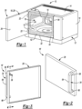
Figure 1 is a front isometric view of a microwave oven; -
Figure 2 is a front isometric view of a first embodiment of a door for the microwave oven; -
Figure 3 is a rear isometric view of the first embodiment of the door for the microwave oven; -
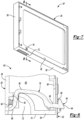
Figure 4 is a cross-sectional view taken along line 4-4 inFigure 3 ; -
Figure 5 is a front isometric view of a first embodiment of a latch for the microwave oven door; -
Figure 6 is a rear isometric view of the first embodiment of the latch for the microwave oven door; -
Figure 7 is a lower rear isometric view of a second embodiment of the door for the microwave oven; -
Figure 8 is a cross-sectional view taken along line 8-8 inFigure 7 ; -
Figure 9 is a top isometric view of a second embodiment of a latch for the microwave oven door; and -
Figure 10 is a bottom isometric view of the second embodiment of the latch for the microwave oven door. - Embodiments of the present disclosure are described herein. It is to be understood, however, that the disclosed embodiments are merely examples and other embodiments may take various and alternative forms. The figures are not necessarily to scale; some features could be exaggerated or minimized to show details of particular components. Therefore, specific structural and functional details disclosed herein are not to be interpreted as limiting, but merely as a representative basis for teaching one skilled in the art to variously employ the embodiments. As those of ordinary skill in the art will understand, various features illustrated and described with reference to any one of the figures may be combined with features illustrated in one or more other figures to produce embodiments that are not explicitly illustrated or described. The combinations of features illustrated provide representative embodiments for typical applications. Various combinations and modifications of the features consistent with the teachings of this disclosure, however, could be desired for particular applications or implementations.
- Referring to
Figure 1 , a front isometric view of amicrowave oven 10 is illustrated. Themicrowave oven 10 includes ahousing 12. The housing includes a plurality of panels orwalls 14 that define aninternal cavity 16 in which food may be placed or received for cooking. The plurality ofwalls 14 may include a top wall, a bottom wall, and three side walls. Thehousing 12 may further define anopening 20 configured to provide access to theinternal cavity 16. Themicrowave oven 10 also includes adoor 18 that is rotatably attached or secured to the to thehousing 12. For example, thedoor 18 may be rotatably secured or attached to thehousing 12 viahinges 22 along a first end orfirst side 24 of thedoor 18. - A handle (not shown in
Figure 1 ) may be secured to or defined along a second end orsecond side 26 of thedoor 18. Thedoor 18 may comprise apanel 28 and said handle, where thepanel 28 may be rotatably secured or attached to thehousing 12 via the hinges 22. More specifically, thepanel 28 may be comprised of a plurality of plates, external panels, or subpanels that are secured to each other and define an internal pocket or cavity (not shown inFigure 1 ). For example, thepanel 28 may comprise a plurality of metal plates or sheet metal subpanels that are secured to each other and define an internal pocket or cavity. Thedoor 18 is configuring to pivot relative to thehousing 12 via thehinges 22 in response to a user engaging the handle to transition the door between anopen position 30 and aclosed position 32. Thedoor 18 provides access to theopening 20 andinternal cavity 16 when in theopen position 30. Thedoor 18 covers theopening 20 andinternal cavity 16 when in theclosed position 32. Thedoor 18 may be one of several embodiments described in further detail below. Therefore, thedoor 18 as illustrated inFigure 1 should not be construed as limiting. - Referring to
Figure 2-6 , a first embodiment of the door 18' and a corresponding latching system for the door 18' are illustrated. The door 18' includes thepanel 28 and ahandle 34 protruding outward from thepanel 28. The door 18' also includes alatch 36 that protrudes outward from thepanel 28 along an opposing side of thepanel 28 relative to thehandle 34. As previously stated, thepanel 28 may more specifically be comprised of a plurality of plates, external panels, orsubpanels 38 that are secured to each other and define an internal cavity orpocket 40. Thehandle 34 may protrude outward from a first of thesubpanels 38 that faces away from thehousing 12 while thelatch 36 may protrude outward from a second of thesubpanels 38 that faces toward thehousing 12. - The
latch 36 is disposed within theinternal pocket 40. Thelatch 36 is pivotably secured to the door 18' within theinternal pocket 40 and is configured to pivot about anaxis 42 relative to the door 18'. More specifically, thelatch 36 may include apivot pin 44 about which thelatch 36 pivots relative to the door 18'. Each end of thepivot pin 44 may be disposed within a bushing hole ororifice 46 defined by the door 18' internally within theinternal pocket 40. Thepivot pin 44 may be rotatable about theaxis 42 within the bushing holes ororifices 46. Thelatch 36 includes alatch hook 48 and apush button 50. - The
latch hook 48 protrudes outward from theinternal pocket 40 along one of theexternal panels 38 and extends toward thehousing 12. Thelatch hook 48 also extends beyond an external surface of the door 18'. More specifically, thelatch hook 48 extends toward afront panel 52 of thehousing 12. Thelatch hook 48 is configured to engage thehousing 12 to lock the door 18' to thehousing 12 in theclosed position 32. More specifically, thelatch hook 48 is configured to extend through a notch, groove, or slot 54 defined by thefront panel 52 of thehousing 12 and a flat stoppingsurface 56 that extends upward along aback side of thelatch hook 48 is configured to engage a backside of thefront panel 52 to lock the door 18' to thehousing 12 in theclosed position 32. Aspring 58 may bias thelatch hook 48 upward so that the flat stoppingsurface 56 is aligned with the backside of thefront panel 52 when thelatch hook 48 is extended through theslot 54, and so that the door 18' automatically remains locked to thehousing 12 when the door 18' is in theclosed position 32. Thelatch 36 may include aprotrusion 59 that functions to retain thespring 58 so thatspring 58 remains in contact with thelatch 36. Thespring 58 may engage both thelatch 36 and an internal surface within the door 18', or more specifically an internal surface within thehandle 34. - The
latch hook 48 is configured to disengage thehousing 12 to unlock the door 18' from thehousing 12. More specifically, to unlock the door 18' from thehousing 12 while the door 18' is in theclosed position 32, thelatch hook 48 is rotated downward via thepivot pin 44 so that the flat stoppingsurface 56 is no longer aligned with the backside of thefront panel 52 but is instead aligned with theslot 54 defined by thefront panel 52 of thehousing 12. Once the flat stoppingsurface 56 is aligned with theslot 54 the door 18' may freely transition between theopen position 30 and theclosed position 32. - The
latch hook 48 may be rotated downward via thepivot pin 44 so that the flat stoppingsurface 56 is aligned with theslot 54 by depressing thepush button 50. Thepush button 50 may be rigidly interconnected to thelatch hook 48 within theinternal pocket 40. Thepush button 50 and thelatch hook 48 are configured to collectively pivot via thepivot pin 44 about theaxis 42 in response to depression of thepush button 50 to disengage thelatch hook 48 from the housing 12 (e.g., to align flat stoppingsurface 56 with the slot 54) in order to unlock the door 18' from thehousing 12. Thelatch hook 48 may also include a rampedsurface 60. The rampedsurface 60 may engage thefront panel 52 of thehousing 12 proximate to or within theslot 54 while the door 18' is being transitioned to theclosed position 32 so that thelatch hook 48 is forced downward, allowing thelatch hook 48 to extend through theslot 54 without thepush button 50 being depressed. Once thelatch hook 48 is beyond theslot 54, thelatch hook 48 is forced upward via thespring 58 to lock the door 18' to thehousing 12 in theclosed position 32. The rampingsurface 60 allows the door 18' to transition to theclosed position 32 and automatically lock without depressing thepush button 50. - Rigidly interconnected may refer to components that are connected or secured to each other such that relative positions of the components to each other remain the same, particularly under operating conditions. For example, if the position of a first component is changed, the position of a second components that is rigidly interconnected with the first component will also change so that the relative positions of the first and second components to each other remain the same. Multiple components formed as a single solid piece are rigidly interconnected. Multiple components secured to each other without moveable joints are rigidly interconnected. Relative positions of rigidly interconnected components may be considered to remain the same in the event minor deflections of the components occur when external forces are applied to the components, so long as such minor deflections do not affect the functionality of the components. Such minor deflections may include deflections that are not detectable or observable by a person.
- The
push button 50 protrudes outward from thehandle 34. More specifically, thepush button 50 extends outward from thehandle 34 through a notch, groove, or slot defined by thehandle 34. Thelatch 36 includes a plurality of linkingarms 62 rigidly interconnecting thelatch hook 48 to thepush button 50. Thelatch hook 48,push button 50, and plurality of linkingarms 62 may form a single solid component. At least two of the plurality of linkingarms 62 are non-linear relative to each other. A first and a second of the linkingarms 62 may be substantially perpendicular to each other. Substantially perpendicular may refer to any incremental angle is that is between exactly perpendicular and 15° from exactly perpendicular. - The
handle 34 may be C-shaped. Thehandle 34 may have acentral portion 64 that is spaced-apart from thepanel 28. More specifically, thecentral portion 64 may be spaced apart from the first of thesubpanels 38 that faces away from thehousing 12. Thehandle 34 may also have opposing ends 66 that are each secured to thepanel 28. More specially, the opposing ends 66 may each be secured to the first of thesubpanels 38 that faces away from thehousing 12. - The
handle 34 may define an internal channel 68 that is in communication within the in theinternal pocket 40. The internal channel 68 may also be said to form a portion of theinternal pocket 40. Thepush button 50 is rigidly interconnected to thelatch hook 48 via the linkingarms 62, which extend through the internal channel 68 and/or theinternal pocket 40. Thepush button 50 more specifically may protrude outward from anexternal surface 70 of thecentral portion 64 of thehandle 34. Theexternal surface 70 may be one any of the external surfaces of thehandle 34, but may more specifically be the external surface of thecentral portion 64 of thehandle 34 that faces toward thepanel 28. More specially, theexternal surface 70 may face the first of thesubpanels 38 that faces away from thehousing 12. - Referring to
Figure 7-10 , a second embodiment of thedoor 18" and a corresponding latching system for thedoor 18" are illustrated. Thedoor 18" includes thepanel 28 and defines apocket handle 72 along a lower orbottom edge 74 of thedoor 18". Thedoor 18" also includeslatch 76 that protrudes outward from thepanel 28. As previously stated, thepanel 28 may more specifically be comprised of a plurality of plates, external panels, orsubpanels 38 that are secured to each other and define an internal cavity orpocket 40. - The
latch 76 is disposed within theinternal pocket 40. Thelatch 76 is pivotably secured to thedoor 18" within theinternal pocket 40 and is configured to pivot about anaxis 78 relative to thedoor 18". More specifically, thelatch 36 may include apivot pin 80 about which thelatch 76 pivots relative to thedoor 18". Each end of thepivot pin 80 may be disposed within a bushing hole ororifice 82 defined by thedoor 18" internally within theinternal pocket 40. Thepivot pin 80 may be rotatable about theaxis 78 within the bushing holes ororifices 82. Thelatch 76 includes alatch hook 84 and apush button 86. - The
latch hook 84 protrudes outward from theinternal pocket 40 along one of theexternal panels 38 and extends toward thehousing 12. Thelatch hook 84 also extends beyond an external surface of thedoor 18". More specifically, thelatch hook 84 extends toward thefront panel 52 of thehousing 12. Thelatch hook 84 is configured to engage thehousing 12 to lock thedoor 18" to thehousing 12 in theclosed position 32. More specifically, thelatch hook 84 is configured to extend through the notch, groove, or slot 54 defined by thefront panel 52 of thehousing 12 and a flat stoppingsurface 88 that extends upward along aback side of thelatch hook 48 is configured to engage a backside of thefront panel 52 to lock thedoor 18" to thehousing 12 in theclosed position 32. One ormore springs 90 may bias thelatch hook 84 upward so that the flat stoppingsurface 88 is aligned with the backside of thefront panel 52 when thelatch hook 84 is extended through theslot 54, and so that thedoor 18" automatically remains locked to thehousing 12 when thedoor 18" is in theclosed position 32. Thelatch 76 may includeprotrusions 92 that function to retain thesprings 90 so that springs 90 remain in contact with thelatch 76. Thesprings 90 may engage both thelatch 76 and an internal surface within thedoor 18", or more specifically an internal surface within thepocket handle 72. - The
latch hook 84 is configured to disengage thehousing 12 to unlock thedoor 18" from thehousing 12. More specifically, to unlock thedoor 18" from thehousing 12 while thedoor 18" is in theclosed position 32, thelatch hook 84 is rotated downward via thepivot pin 80 so that the flat stoppingsurface 88 is no longer aligned with the backside of thefront panel 52 but is instead aligned with theslot 54 defined by thefront panel 52 of thehousing 12. Once the flat stoppingsurface 88 is aligned with theslot 54 thedoor 18" may freely transition between theopen position 30 and theclosed position 32. - The
latch hook 84 may be rotated downward via thepivot pin 80 so that the flat stoppingsurface 88 is aligned with theslot 54 by depressing thepush button 86. Thepush button 86 may be rigidly interconnected to thelatch hook 84 within theinternal pocket 40. Thepush button 86 and thelatch hook 84 are configured to collectively pivot via thepivot pin 80 about theaxis 78 in response to depression of thepush button 86 to disengage thelatch hook 84 from the housing 12 (e.g., to align flat stoppingsurface 88 with the slot 54) in order to unlock thedoor 18" from thehousing 12. Depression of thepush button 86 may include pulling thepush button 86 in a direction away from thehousing 12. Thelatch hook 84 may also include a rampedsurface 94. The rampedsurface 94 may engage thefront panel 52 of thehousing 12 proximate to or within theslot 54 while thedoor 18" is being transitioned to theclosed position 32 so that thelatch hook 84 is forced downward, allowing thelatch hook 84 to extend through theslot 54 without thepush button 86 being depressed. Once thelatch hook 84 is beyond theslot 54, thelatch hook 84 is forced upward via the one ormore springs 90 to lock thedoor 18" to thehousing 12 in theclosed position 32. The rampingsurface 94 allows thedoor 18" to transition to theclosed position 32 and automatically lock without depressing thepush button 86. - The
push button 86 extends downward from theinternal pocket 40 and into thepocket handle 72. More specifically, thepush button 86 extends downward into pocket handle 72 through a notch, groove, or slot defined by an internal surface within thepocket handle 72. Thelatch 76 includes a plurality of linkingarms 96 rigidly interconnecting thelatch hook 84 to thepush button 86. Thelatch hook 84,push button 86, and plurality of linkingarms 96 may form a single solid component. At least two of the plurality of linkingarms 96 may be non-linear relative to each other. - The
microwave oven 10 may include a microwave generating device, such as a magnetron or a solid-state device. Themicrowave oven 10 may include a waveguide that defines a pathway or channel on an opposing side of a wall of the plurality ofwalls 14 relative to theinternal cavity 16. The wall of the plurality ofwalls 14 may define an orifice that establishes communication between theinternal cavity 16 and the pathway or channel. A waveguide cover may be disposed over the orifice within theinternal cavity 16. The pathway or channel of the waveguide is configured to direct microwaves from the microwave generating device, through the waveguide cover, and to theinternal cavity 16 in order to cook any food that is disposed within theinternal cavity 16. - The
microwave oven 10 may also include a power supply, such as a transformer, that provides electrical power to the microwave generating device, a capacitor, and a cooling fan. The cooling fan may be configured to cool the various components of themicrowave oven 10, such as the microwave generating device, power supply, capacitor, etc. Please note that for illustrative purposes, the electrical connections between the various components of themicrowave oven 10 and the electrical connection between themicrowave 10 and an external power source (e.g., an electrical plug and outlet connection) are not shown. - The electronic components (e.g., microwave generating device, fan motors, power supply, capacitors, etc.) of the
microwave oven 10 may be connected to a control panel, such as a human machine interface (HMI), and a controller, so that an operator may control various parameters. For example, the operator may be configured to input a cooking time, a cooking temperature, a desired mode of cooking (e.g., microwave cooking, defrost, etc.). - The controller may be part of a larger control system and may be controlled by various other controllers throughout the
microwave oven 10. It should therefore be understood that the controller and one or more other controllers can collectively be referred to as a "controller" that controls various functions or components of themicrowave oven 10 in response to signals from various sensors to control the various functions or components of themicrowave oven 10. The controller may include a microprocessor or central processing unit (CPU) in communication with various types of computer readable storage devices or media. Computer readable storage devices or media may include volatile and nonvolatile storage in read-only memory (ROM), random-access memory (RAM), and keep-alive memory (KAM), for example. KAM is a persistent or non-volatile memory that may be used to store various operating variables while the CPU is powered down. Computer-readable storage devices or media may be implemented using any of a number of known memory devices such as PROMs (programmable read-only memory), EPROMs (electrically PROM), EEPROMs (electrically erasable PROM), flash memory, or any other electric, magnetic, optical, or combination memory devices capable of storing data, some of which represent executable instructions, used by the controller in controlling themicrowave oven 10. - It should be understood that any component having a callout number that includes one or prime symbols (') should be construed as having the same structure, subcomponents, and functionality as a component that includes the same callout number but without the one or prime symbols, unless otherwise stated or illustrated herein. It should also be understood that the designations of first, second, third, fourth, etc. for any component, state, or condition described herein may be rearranged in the claims so that they are in chronological order with respect to the claims. Furthermore, it should be understood that any component, state, or condition described herein that does not have a numerical designation may be given a designation of first, second, third, fourth, etc. in the claims if one or more of the specific component, state, or condition are claimed.
Claims (15)
- A microwave oven (10) comprising:a housing (12) defining an internal cavity (16) configured to receive food for cooking and an opening (20) configured to provide access to the internal cavity (16);a door (18, 18', 18") rotatably secured to the housing (12), having external panels (38) defining an internal pocket (40), and having a handle (34, 72), wherein the door (18, 18', 18") is configuring to pivot relative to the housing (12) in response to a user engaging the handle (34, 72) to transition the door (18, 18', 18") between an open position (30) and a closed position (32), provides access to the opening (20) in the open position (30), and covers the opening (20) in the closed position (32); anda latch (36, 76) pivotably secured to the door (18, 18', 18") within the internal pocket (40) and configured to pivot about an axis (42, 78) relative to the door (18, 18', 18"), the latch (36, 76) havinga latch hook (48, 84) protruding outward from the internal pocket (40) along a first of the external panels (38), extending toward the housing (12), configured to engage the housing (12) to lock the door (18, 18', 18") to the housing (12) in the closed position (32), and configured to disengage the housing (12) to unlock the door (18, 18', 18") from the housing (12), wherein the first of the external panels (38) faces toward the housing (12), anda push button (50, 86) protruding outward from the handle (34, 72) and rigidly interconnected to the latch hook (48, 84) within the internal pocket (40), wherein the push button (50, 86) and the latch hook (48, 84) are configured to collectively pivot about the axis (42, 78) in response to depression of the push button (50, 86) to disengage the latch hook (48, 84) from the housing (12).
- The microwave oven (10) of claim 1, wherein the latch (36, 76) includes a plurality of linking arms (62, 96) rigidly interconnecting the latch hook (48, 84) to the push button (50, 86).
- The microwave oven (10) of claim 2, wherein the latch hook (48, 84), push button (50, 86), and plurality of linking arms (62, 96) form a single solid component.
- The microwave oven (10) of claim 2, wherein at least two of the plurality of linking arms (62, 96) are non-linear relative to each other.
- The microwave oven (10) of claim 1, wherein the handle (34) is C-shaped, has a central portion (64) that is spaced-apart from a second of the external panels (38), and has opposing ends (66) each secured to the second of the external panels (38).
- The microwave oven (10) of claim 5, wherein the second of the external panels (38) faces away from the housing (12).
- The microwave oven (10) of claim 5, wherein the handle (34) defines an internal channel (68) that is in communication with the internal pocket (40).
- The microwave oven (10) of claim 7, wherein the push button (50) is rigidly interconnected with the latch hook (48) via first and second linking arms (62) extending through the internal channel (68) and the internal pocket (40).
- The microwave oven (10) of claim 8, wherein the first and second linking arms (62) are substantially perpendicular to each other.
- The microwave oven (10) of claim 5, wherein the push button (50) protrudes outward from an external surface (70) of the central portion of the handle (34).
- The microwave oven (10) of claim 10, wherein the external surface (70) faces toward the second of the external panels (38) of the door (18').
- The microwave oven (10) of claim 1, wherein the handle (72) is a pocket handle (72) defined along a bottom edge (74) of the door (18").
- The microwave oven (10) of claim 12, wherein the push button (86) is disposed within the pocket handle (72).
- The microwave oven (10) of claim 1 further comprising a spring (58, 90) configured to bias the latch hook (48, 84) toward engagement with the housing (12).
- The microwave oven (10) of claim 14, wherein the latch (36, 76) includes a protrusion (59, 92) configured to retain the spring (58, 90).
Applications Claiming Priority (1)
| Application Number | Priority Date | Filing Date | Title |
|---|---|---|---|
| US17/732,961 US12414206B2 (en) | 2022-04-29 | 2022-04-29 | Latch system for microwave oven door |
Publications (1)
| Publication Number | Publication Date |
|---|---|
| EP4271131A1 true EP4271131A1 (en) | 2023-11-01 |
Family
ID=86272516
Family Applications (1)
| Application Number | Title | Priority Date | Filing Date |
|---|---|---|---|
| EP23170464.4A Withdrawn EP4271131A1 (en) | 2022-04-29 | 2023-04-27 | Latch system for microwave oven door |
Country Status (2)
| Country | Link |
|---|---|
| US (1) | US12414206B2 (en) |
| EP (1) | EP4271131A1 (en) |
Citations (3)
| Publication number | Priority date | Publication date | Assignee | Title |
|---|---|---|---|---|
| JPS5087545U (en) * | 1973-12-13 | 1975-07-25 | ||
| JPS5163245U (en) * | 1974-11-12 | 1976-05-18 | ||
| JPS5974434A (en) * | 1982-10-22 | 1984-04-26 | Toshiba Corp | High-frequency heating apparatus |
Family Cites Families (7)
| Publication number | Priority date | Publication date | Assignee | Title |
|---|---|---|---|---|
| US4321445A (en) * | 1980-01-28 | 1982-03-23 | Whirlpool Corporation | Door latch interlock system for microwave oven |
| JPS57129329A (en) | 1981-02-02 | 1982-08-11 | Matsushita Electric Ind Co Ltd | High-frequency heating device |
| JPS59198620A (en) | 1983-04-26 | 1984-11-10 | シャープ株式会社 | Switch mechanism of cooking device |
| GB2207179B (en) | 1987-07-09 | 1991-09-18 | Gold Star Co | Door latch assembly |
| AU596039B2 (en) | 1988-05-20 | 1990-04-12 | Kabushiki Kaisha Toshiba | Cooker |
| US4875721A (en) * | 1988-11-10 | 1989-10-24 | Imanishi Kinzoku Kogyo Kabushiki Kaisha | Latch assembly for door or window of microwave range |
| KR100273874B1 (en) * | 1997-11-15 | 2000-12-15 | 구자홍 | Structure for opening and closing of microwave oven |
-
2022
- 2022-04-29 US US17/732,961 patent/US12414206B2/en active Active
-
2023
- 2023-04-27 EP EP23170464.4A patent/EP4271131A1/en not_active Withdrawn
Patent Citations (3)
| Publication number | Priority date | Publication date | Assignee | Title |
|---|---|---|---|---|
| JPS5087545U (en) * | 1973-12-13 | 1975-07-25 | ||
| JPS5163245U (en) * | 1974-11-12 | 1976-05-18 | ||
| JPS5974434A (en) * | 1982-10-22 | 1984-04-26 | Toshiba Corp | High-frequency heating apparatus |
Also Published As
| Publication number | Publication date |
|---|---|
| US20230354485A1 (en) | 2023-11-02 |
| US12414206B2 (en) | 2025-09-09 |
Similar Documents
| Publication | Publication Date | Title |
|---|---|---|
| US6333495B1 (en) | Safety device for a microwave oven | |
| US8796603B2 (en) | Appliance with a pair of connectors connected to printed circuit boards located in the cabinet and the door | |
| EP3560288B1 (en) | Cooking apparatus | |
| KR102676839B1 (en) | Oven | |
| CN215803931U (en) | Door lock structure and cooking equipment | |
| US12414206B2 (en) | Latch system for microwave oven door | |
| US7034269B2 (en) | Wall-mounted microwave oven | |
| EP3282817B1 (en) | Structure for covering connection line, electric cooking appliance including the same, and method of assembling cap of electric cooking appliance | |
| KR100399138B1 (en) | Microwave oven | |
| US10306711B2 (en) | Microwave oven with dual doors | |
| EP4048028A1 (en) | Convection system for an oven | |
| KR100487327B1 (en) | microwave oven range with toaster | |
| CN221400153U (en) | Cooking utensil and door lock device thereof | |
| KR100546902B1 (en) | Latch Board Structure of Microwave Oven | |
| EP2194757B1 (en) | Microwave oven | |
| US6300610B1 (en) | Microwave oven with door latching member | |
| KR100487323B1 (en) | Microwave Oven with Toaster | |
| CN223378084U (en) | Tilting switch mounting structure and electric appliance | |
| CN222811802U (en) | Heating apparatus | |
| US20260043550A1 (en) | Method of operating an oven appliance | |
| US20260043549A1 (en) | Method of operating an oven appliance | |
| CN212958136U (en) | Safe door opening mechanism and cooking appliance | |
| US5895601A (en) | Door lock mechanism with a duct for a microwave oven | |
| CN219864535U (en) | Door lock structure and cooking equipment | |
| JPH1047688A (en) | High-frequency heater |
Legal Events
| Date | Code | Title | Description |
|---|---|---|---|
| PUAI | Public reference made under article 153(3) epc to a published international application that has entered the european phase |
Free format text: ORIGINAL CODE: 0009012 |
|
| STAA | Information on the status of an ep patent application or granted ep patent |
Free format text: STATUS: THE APPLICATION HAS BEEN PUBLISHED |
|
| AK | Designated contracting states |
Kind code of ref document: A1 Designated state(s): AL AT BE BG CH CY CZ DE DK EE ES FI FR GB GR HR HU IE IS IT LI LT LU LV MC ME MK MT NL NO PL PT RO RS SE SI SK SM TR |
|
| P01 | Opt-out of the competence of the unified patent court (upc) registered |
Effective date: 20231220 |
|
| STAA | Information on the status of an ep patent application or granted ep patent |
Free format text: STATUS: REQUEST FOR EXAMINATION WAS MADE |
|
| 17P | Request for examination filed |
Effective date: 20240426 |
|
| RBV | Designated contracting states (corrected) |
Designated state(s): AL AT BE BG CH CY CZ DE DK EE ES FI FR GB GR HR HU IE IS IT LI LT LU LV MC ME MK MT NL NO PL PT RO RS SE SI SK SM TR |
|
| STAA | Information on the status of an ep patent application or granted ep patent |
Free format text: STATUS: THE APPLICATION HAS BEEN WITHDRAWN |
|
| 18W | Application withdrawn |
Effective date: 20250311 |