EP4270919A1 - Camera module and electronic device - Google Patents
Camera module and electronic device Download PDFInfo
- Publication number
- EP4270919A1 EP4270919A1 EP21909247.5A EP21909247A EP4270919A1 EP 4270919 A1 EP4270919 A1 EP 4270919A1 EP 21909247 A EP21909247 A EP 21909247A EP 4270919 A1 EP4270919 A1 EP 4270919A1
- Authority
- EP
- European Patent Office
- Prior art keywords
- support plate
- driving assembly
- camera module
- board
- coil
- Prior art date
- Legal status (The legal status is an assumption and is not a legal conclusion. Google has not performed a legal analysis and makes no representation as to the accuracy of the status listed.)
- Pending
Links
Images



Classifications
-
- H—ELECTRICITY
- H04—ELECTRIC COMMUNICATION TECHNIQUE
- H04N—PICTORIAL COMMUNICATION, e.g. TELEVISION
- H04N23/00—Cameras or camera modules comprising electronic image sensors; Control thereof
- H04N23/50—Constructional details
- H04N23/54—Mounting of pick-up tubes, electronic image sensors, deviation or focusing coils
-
- H—ELECTRICITY
- H04—ELECTRIC COMMUNICATION TECHNIQUE
- H04N—PICTORIAL COMMUNICATION, e.g. TELEVISION
- H04N23/00—Cameras or camera modules comprising electronic image sensors; Control thereof
- H04N23/50—Constructional details
- H04N23/51—Housings
-
- G—PHYSICS
- G02—OPTICS
- G02B—OPTICAL ELEMENTS, SYSTEMS OR APPARATUS
- G02B27/00—Optical systems or apparatus not provided for by any of the groups G02B1/00 - G02B26/00, G02B30/00
- G02B27/64—Imaging systems using optical elements for stabilisation of the lateral and angular position of the image
- G02B27/646—Imaging systems using optical elements for stabilisation of the lateral and angular position of the image compensating for small deviations, e.g. due to vibration or shake
-
- H—ELECTRICITY
- H04—ELECTRIC COMMUNICATION TECHNIQUE
- H04M—TELEPHONIC COMMUNICATION
- H04M1/00—Substation equipment, e.g. for use by subscribers
- H04M1/02—Constructional features of telephone sets
- H04M1/0202—Portable telephone sets, e.g. cordless phones, mobile phones or bar type handsets
- H04M1/026—Details of the structure or mounting of specific components
- H04M1/0264—Details of the structure or mounting of specific components for a camera module assembly
-
- H—ELECTRICITY
- H04—ELECTRIC COMMUNICATION TECHNIQUE
- H04N—PICTORIAL COMMUNICATION, e.g. TELEVISION
- H04N23/00—Cameras or camera modules comprising electronic image sensors; Control thereof
- H04N23/50—Constructional details
- H04N23/55—Optical parts specially adapted for electronic image sensors; Mounting thereof
-
- H—ELECTRICITY
- H04—ELECTRIC COMMUNICATION TECHNIQUE
- H04N—PICTORIAL COMMUNICATION, e.g. TELEVISION
- H04N23/00—Cameras or camera modules comprising electronic image sensors; Control thereof
- H04N23/57—Mechanical or electrical details of cameras or camera modules specially adapted for being embedded in other devices
-
- H—ELECTRICITY
- H04—ELECTRIC COMMUNICATION TECHNIQUE
- H04N—PICTORIAL COMMUNICATION, e.g. TELEVISION
- H04N23/00—Cameras or camera modules comprising electronic image sensors; Control thereof
- H04N23/60—Control of cameras or camera modules
- H04N23/68—Control of cameras or camera modules for stable pick-up of the scene, e.g. compensating for camera body vibrations
- H04N23/682—Vibration or motion blur correction
- H04N23/685—Vibration or motion blur correction performed by mechanical compensation
-
- H—ELECTRICITY
- H04—ELECTRIC COMMUNICATION TECHNIQUE
- H04N—PICTORIAL COMMUNICATION, e.g. TELEVISION
- H04N23/00—Cameras or camera modules comprising electronic image sensors; Control thereof
- H04N23/60—Control of cameras or camera modules
- H04N23/68—Control of cameras or camera modules for stable pick-up of the scene, e.g. compensating for camera body vibrations
- H04N23/682—Vibration or motion blur correction
- H04N23/685—Vibration or motion blur correction performed by mechanical compensation
- H04N23/687—Vibration or motion blur correction performed by mechanical compensation by shifting the lens or sensor position
-
- H—ELECTRICITY
- H05—ELECTRIC TECHNIQUES NOT OTHERWISE PROVIDED FOR
- H05K—PRINTED CIRCUITS; CASINGS OR CONSTRUCTIONAL DETAILS OF ELECTRIC APPARATUS; MANUFACTURE OF ASSEMBLAGES OF ELECTRICAL COMPONENTS
- H05K1/00—Printed circuits
- H05K1/02—Details
- H05K1/0277—Bendability or stretchability details
-
- H—ELECTRICITY
- H05—ELECTRIC TECHNIQUES NOT OTHERWISE PROVIDED FOR
- H05K—PRINTED CIRCUITS; CASINGS OR CONSTRUCTIONAL DETAILS OF ELECTRIC APPARATUS; MANUFACTURE OF ASSEMBLAGES OF ELECTRICAL COMPONENTS
- H05K1/00—Printed circuits
- H05K1/18—Printed circuits structurally associated with non-printed electric components
- H05K1/189—Printed circuits structurally associated with non-printed electric components characterised by the use of flexible or folded printed circuits
-
- H—ELECTRICITY
- H05—ELECTRIC TECHNIQUES NOT OTHERWISE PROVIDED FOR
- H05K—PRINTED CIRCUITS; CASINGS OR CONSTRUCTIONAL DETAILS OF ELECTRIC APPARATUS; MANUFACTURE OF ASSEMBLAGES OF ELECTRICAL COMPONENTS
- H05K2201/00—Indexing scheme relating to printed circuits covered by H05K1/00
- H05K2201/10—Details of components or other objects attached to or integrated in a printed circuit board
- H05K2201/10007—Types of components
- H05K2201/10121—Optical component, e.g. opto-electronic component
Definitions
- This application belongs to the technical field of cameras, and specifically relates to a camera module and an electronic device.
- This application aims to provide a camera module and an electronic device, and at least resolves one of the problems in the background technology.
- an embodiment of this application provides a camera module, including: a housing, internally provided with an accommodation cavity; a lens assembly, movably arranged in the accommodation cavity; a circuit board, connected to the lens assembly; and a gimbal assembly, including: a support plate, where at least part of the support plate is movably arranged in the accommodation cavity, and the lens assembly and the circuit board are arranged on the support plate; a first driving assembly, where the first driving assembly is arranged on the housing, and at least part of the first driving assembly is connected to the support plate to drive the support plate to move in a first direction; and a second driving assembly, where the second driving assembly is arranged on the support plate, and at least part of the second driving assembly is connected to the support plate to drive the support plate to move in a second direction.
- an embodiment of this application provides an electronic device, including the foregoing camera module.
- the support plate is connected to the lens assembly and the circuit board respectively, and the first driving assembly and the second driving assembly cooperate with each other to drive the support plate to move in the first direction and the second direction.
- the support plate can drive the lens assembly and the circuit board to move synchronously, which can prevent the lens assembly from dragging the circuit board during moving, reduce a volume of the overall structure of the camera module, improve the flexibility of the support plate, and expand the movement range of the support plate.
- a feature defined to be “first” or “second” may explicitly or implicitly include one or more features.
- the meaning of “a plurality of” is two or more than two.
- “and/or” represents at least one of the connected objects, and the character “/” generally indicates an “or” relationship between the associated objects.
- orientations or position relationships indicated by terms such as “center”, “longitudinal”, “transverse”, “length”, “width”, “thickness”, “up”, “down”, “front”, “back”, “left”, “right”, “vertical”, “horizontal”, “top”, “bottom”, “inner”, “outer”, “clockwise”, “counterclockwise”, “axial”, “radial”, and “circumferential” are orientations or position relationship shown based on the accompanying drawings, and are merely used for describing this application and simplifying the description, rather than indicating or implying that the apparatus or element should have a particular orientation or be constructed and operated in a particular orientation, and therefore, should not be construed as a limitation on this application.
- connection should be understood broadly, for example, the connection may be fixed connection, detachable connection, or integral connection; or the connection may be a mechanical connection or an electrical connection; or the connection may be a direct connection, an indirect connection through an intermediary, or internal communication between two components.
- This application is an invention by the creator based on the following facts.
- FIG. 1 shows an image stabilization gimbal in the related art.
- a camera module in the image stabilization gimbal uses a dangling structure.
- an electromagnetic driving system Through the cooperation of a cross support shaft 1 with a connected diagonal line, an electromagnetic driving system, and a Hall sensing element 2, the camera module is driven to move and the position is fed back, so as to achieve the objective of image stabilization on the module.
- the electromagnetic driving system includes a coil 3 and a magnet 4 cooperating with each other.
- a camera body is embedded in the gimbal, and the electromagnetic driving system is arranged at the outside of the camera body.
- the dangling system and the driving system peculiar to the gimbal result in a large size of the overall gimbal, and lead to big troubles for structure stacking and design of the camera module.
- a camera module 100 includes: a housing 10, a lens assembly 20, a circuit board 30, and a gimbal assembly.
- the gimbal assembly includes: a support plate 40, a first driving assembly 50, and a second driving assembly 60.
- the housing 10 is internally provided with an accommodation cavity 11, and the lens assembly 20 is movably arranged in the accommodation cavity 11.
- the circuit board 30 and the lens assembly 20 are connected to each other.
- the support plate 40 is at least partially movably arranged in the accommodation cavity 11, and the lens assembly 20 and the circuit board 30 are arranged on the support plate 40.
- the first driving assembly 50 is arranged in the housing 10, and at least part of the first driving assembly is connected to the support plate 40 to drive the support plate 40 to move in a first direction.
- the second driving assembly 60 is arranged on the support plate 40, and at least part of the second driving assembly is connected to the support plate 40 to drive the support plate 40 to move in a second direction.
- the camera module 100 mainly includes a housing 10, a lens assembly 20 mounted in the housing 10, a circuit board 30 electrically connected to the lens assembly 20, and a gimbal assembly.
- the gimbal assembly mainly includes a support plate 40 that can limit the lens assembly 20 and the circuit board 30, and a first driving assembly 50 and a second driving assembly 60 that can drive the support plate 40.
- the housing 10 is a basic component of the camera module 100, can provide a basis for mounting other components of the camera module 100, and protects the parts or components such as the driving assembly.
- the housing 10 has an accommodation cavity 11 that can accommodate the lens assembly 20.
- the camera module 100 may incline due to jittering, and eventually affect the photographing quality.
- the lens assembly 20 is movable relative to the housing 10.
- the first driving assembly 50 and the second driving assembly 60 drive the lens assembly 20 to move, so as to compensate an inclination caused by jittering of the camera module 100, thereby implementing effective image stabilization on the camera module 100.
- the lens assembly 20 and the circuit board 30 can move synchronously with the support plate 40, and the support plate 40 may serve as a reinforcement plate. Therefore, when the first driving assembly 50 and the second driving assembly 60 drive the support plate 40 to move, the lens assembly 20 and the circuit board 30 can move simultaneously, so as to prevent the lens assembly 20 from moving relative to the circuit board 30 and dragging the circuit board 30.
- the first driving assembly 50 and the second driving assembly 60 indirectly drive the lens assembly 20 and the circuit board 30 through the support plate 40.
- the circuit board 30 and the lens assembly 20 can move synchronously, which prevents a flexible printed circuit board from dragging the camera body in the related art, and the lens assembly 20 according to this embodiment of this application can move farther and rotate through a larger angle.
- the defect that the volume of the overall structure of the camera module is large because the electromagnetic driving system is mounted on the camera body in the related art is avoided.
- the first driving assembly 50 can drive the support plate 40 to move in the first direction
- the second driving assembly 60 can drive the support plate 40 to move in the second direction
- the first direction and the second direction may be the same direction or reverse directions, or intersect with each other.
- the first driving assembly 50 and the second driving assembly 60 may simultaneously or independently operate.
- Types of movement of the support plate 40 in the first direction and/or the second direction include moving and rotation types. This is not limited herein either.
- any one of the first driving assembly 50 and the second driving assembly 60 includes, but is not limited to, a motor, or may be another driving structure that can enable the support plate 40 to move, such as a driving motor, including a driving motor, a transmission mechanism cooperating with the driving motor, and the like.
- the support plate 40 is connected to the lens assembly 20 and the circuit board 30 respectively, and the first driving assembly 50 and the second driving assembly 60 cooperate with each other to drive the support plate 40 to move in the first direction and the second direction.
- the support plate 40 can drive the lens assembly 20 and the circuit board 30 to move synchronously, which can prevent the lens assembly 20 from dragging the circuit board 30 during moving, reduce a volume of the overall structure of the camera module 100, improve the flexibility of the support plate 40, and expand the movement range of the support plate 40.
- the housing 10 includes: a holder 12 and a cover plate 13.
- the holder 12 is provided with an accommodation cavity 11 with an opening on a first side
- the lens assembly 20 may be arranged in the accommodation cavity 11 and is movable relative to the holder 12, and the circuit board 30 may be connected to the lens assembly 20 through the opening.
- the cover plate 13 is arranged on the first side of the holder 12, and the first driving assembly 50 is arranged on the cover plate 13.
- a part of the first driving assembly 50 may be arranged on the cover plate 13, and another part of the first driving assembly 50 may be arranged on the support plate 40 and is movable relative to the cover plate 13.
- the support plate 40 includes: a main board 41 and a side plate 42.
- the lens assembly 20 and the circuit board 30 are arranged on a first side of the main board 41, the first driving assembly 50 is at least partially located on a second side of the main board 41.
- the side plate 42 is arranged on the first side of the main board 41, and the second driving assembly 60 is arranged on the side plate 42.
- the support plate 40 is divided into the main board 41 and the side plate 42, to facilitate mounting of the first driving assembly 50 and the second driving assembly 60.
- the main board 41 and the side plate 42 are approximately perpendicular to each other.
- the camera module 100 is assembled in an up-down direction, a direction close to a viewer is a front side, and a direction away from the viewer is a rear side.
- the main board 41 is approximately a rectangular plate and extends in a front-rear direction.
- a straight line parallel to a length direction of the main board 41 is referred to as a Y axis
- a straight line parallel to a width direction of the main board 41 is referred to as an X axis
- a straight line perpendicular to a plane in which the main board 41 is located is referred to as a Z axis.
- Each part or component of the camera module 100 may be assembled approximately in the Z-axis direction.
- the lens assembly 20 and the circuit board 30 are located above the main board 41, and the side plate 42 is located above the main board 41.
- a lower end of the side plate 42 is connected to a length side of the main board 41, and an upper end of the side plate 42 extends upward in the Z axis.
- the arrangement of the first driving assembly 50 on the main board 41 can enable the support plate 40 to rotate around the X-axis or Y-axis direction.
- the arrangement of the second driving assembly 60 on the side plate 42 can enable the support plate 40 to rotate around the X-axis or Y-axis direction.
- the circuit board 30 includes: a first board body 31 and a second board body 32.
- the first board body 31 is arranged between the lens assembly 20 and the main board 41, the lens assembly 20 is arranged on a first side of the first board body 31, and a second side of the first board body 31 is connected to the first side of the main board 41.
- the second board body 32 is arranged on the first side of the main board 41, and is electrically connected to the first board body 31.
- the second board body 32 may be a flexible printed circuit board, a conducting wire, or the like. As shown in FIG. 3 , the first board body 31 is located behind the second board body 32 and under the lens assembly 20.
- the housing 10 further includes a flexible printed circuit board receiving portion 70
- the flexible printed circuit board receiving portion 70 may be located in front of the holder 12.
- the second board body 32, the first driving assembly 50, and the second driving assembly 60 may all be located in the flexible printed circuit board receiving portion 70, thereby fully using the receiving space of the flexible printed circuit board receiving portion.
- a shape of the first board body 31 corresponds to a shape of a surface of a first side of the lens assembly 20
- a shape of the main board 41 corresponds to shapes of the first board body 31 and the second board body 32. This improves the stability and reliability of the overall structure when the lens assembly 20 and the circuit board 30 move.
- the first driving assembly 50 includes: a first magnetic member 51 and a first coil 52.
- One of the first magnetic member 51 and the first coil 52 is connected to the cover plate 13, and the other of the first magnetic member 51 and the first coil 52 is connected to the main board 41.
- the first coil 52 is movable relative to the first magnetic member 51 to drive the main board 41.
- the first magnetic member 51 may be arranged on the cover plate 13, and the first coil 52 may be arranged on the main board 41; or the first magnetic member 51 may be arranged on the support plate 40, and the first coil 52 may be arranged on the cover plate 13.
- the first magnetic member 51 is connected to an upper end surface of the cover plate 13.
- the first coil 52 is connected to an upper end surface of the main board 41 and a lower end surface of the second board body 32, and cooperates with the first magnetic member 51.
- the support plate 40 may be of a non-magnetically conductive rigid material.
- the first magnetic member 51 and the first coil 52 cooperate with each other. According to Fleming's left-hand rule, a force perpendicular to a magnetic field direction is generated in the energized first coil 52, and the main board 41 can be controlled to move when the force acts on the main board 41.
- the first magnetic member 51 has a plate-shaped structure, and is attached onto the cover plate 13.
- the first magnetic member 51 may be a flat coil, and can effectively save space.
- the first magnetic member 51 is attached onto the cover plate 13, thereby facilitating the assembly of the first magnetic member 51.
- the first magnetic member 51 may be mounted on the cover plate 13 in another mounting manner, for example, clamping, insertion, or another detachable mounting manner.
- the first coil 52 are two annular coils 521 that are spaced apart on the main board 41. In a case that there are more than two coils 521, the balance of forces can be effectively ensured.
- the two annular coils 521 may respectively be a first annular coil and a second annular coil, and the first annular coil and the second annular coil may share a magnet.
- the main board 41 may rotate around a direction by controlling energization situations of the first annular coil and the second annular coil.
- the second board body 32 is a folded S-shaped flexible board, and the lower end surface of the second board body 32 is approximately a rectangular component. Length sides of the second board body 32 extend in the Y-axis direction, width sides of the second board body 32 extend in the X-axis direction, and the second board body 32 may be folded approximately in the Z-axis direction.
- the first annular coil and the second annular coil are located on the lower end surface of the second board body 32, and are spaced apart in a length direction of the second board body 32.
- the first annular coil and the second annular coil both are an elliptical component that extends approximately in a width direction of the second board body 32.
- the support plate 40 rotates around the X-axis direction.
- the support plate 40 rotates around the Y axis.
- the first annular coil and the second annular coil both are turned on, the balance of forces can be ensured.
- the camera module 100 further includes a first position feedback element 80.
- a movement position of the main board 41 can be fed back through the first position feedback element 80.
- the first position feedback element 80 may be a Hall chip, or the like. This is not limited herein.
- the first position feedback element 80 may be mounted on a hollow structure of the annular coil, thereby saving space.
- each side plate 42 there are two side plates 42.
- the two side plates 42 are arranged opposite to each other on the first side of the main board 41, and each side plate 42 is provided with one second driving assembly 60.
- the two side plates 42 may be spaced apart in the width direction of the main board 41, and each side plate 42 extends in the length direction of the main board 41.
- the second driving assembly 60 includes: a second magnetic member 61 and a second coil 62.
- One of the second magnetic member 61 and the second coil 62 is connected to the side plate 42, and the other of the second magnetic member 61 and the second coil 62 is connected to the housing 10.
- the second coil 62 is movable relative to the second magnetic member 61 to drive the side plate 42.
- the second magnetic member 61 may be arranged on the side plate 42, and the second coil 62 may be arranged on the housing 10; or the second magnetic member 61 may be arranged on the housing 10, and the second coil 62 may be arranged on the side plate 42.
- the second magnetic member 61 is arranged on an inner side wall of the housing 10, and the second coil 62 is arranged on a side of the side plate 42 adjacent to the second board body 32, and cooperates with the second magnetic member 61.
- the second coil 62 After being energized, the second coil 62 is movable relative to the second magnetic member 61 to drive the second board body 32.
- a cooperation principle of the second magnetic member 61 and the second coil 62 is the same as a cooperation principle of the first magnetic member 51 and the first coil 52. This is not described herein again.
- the camera module 100 further includes a second position feedback element 90.
- a movement position of the side plate 42 can be fed back through the second position feedback element 90.
- the second position feedback element 90 may be a Hall chip, or the like. This is not limited herein.
- the second position feedback element 90 may be mounted on a hollow structure of the annular coil, thereby saving space.
- first driving assembly 50 and the second driving assembly 60 may operate independently, or may operate cooperatively.
- the support plate 40 can rotate around the X axis and the support plate 40 can rotate around the Y axis.
- the support plate 40 is driven to move, so that the support plate 40 rotates around the X axis.
- F1 and F3 are combined into one group that is represented by [F1, F3]; and in a case that the directions of F2 and F4 are the same, F2 and F4 are combined into one group that is represented by [F2, F4].
- [F1, F3] and [F2, F4] are reverse, the support plate 40 is driven to rotate around the Y axis.
- the second magnetic member 61 has a plate-shaped structure, and is attached onto the side plate 42. This has advantages of facilitating assembly and saving the mounting space.
- An embodiment of this application further provides an electronic device, including the camera module 100 according to any one of the foregoing embodiments.
- the lens assembly 20 may be electrically connected to the main board 41 of the electronic device through the circuit board 30, to supply power to the lens assembly 20.
- the electronic device may be a smart phone, a tablet computer, a wearable device, or the like. This is not limited herein.
Landscapes
- Engineering & Computer Science (AREA)
- Signal Processing (AREA)
- Multimedia (AREA)
- Physics & Mathematics (AREA)
- General Physics & Mathematics (AREA)
- Optics & Photonics (AREA)
- Microelectronics & Electronic Packaging (AREA)
- Studio Devices (AREA)
- Adjustment Of Camera Lenses (AREA)
- Camera Bodies And Camera Details Or Accessories (AREA)
Abstract
Description
- This application claims priority to
Chinese Patent Application No. 202011542405.X filed on December 23, 2020 - This application belongs to the technical field of cameras, and specifically relates to a camera module and an electronic device.
- The wider application of cameras on electronic devices, especially mobile phones, makes cameras a popular selling point for mobile phones. During photographing and image recording, jitters caused by a hand or movement of a user blur the image and greatly lower the imaging quality. In the 5G era, video creating and sharing will usher in a new round of explosion, and requirements of people on video shooting devices are becoming higher. This requires electronic devices to have good image stabilization performance, compensate image offsets caused by jitters, and provide stable and clear images. Currently, the design of image stabilization gimbals has a large volume and has high requirements on the hardware architectural design of electronic devices.
- This application aims to provide a camera module and an electronic device, and at least resolves one of the problems in the background technology.
- According to a first aspect, an embodiment of this application provides a camera module, including: a housing, internally provided with an accommodation cavity; a lens assembly, movably arranged in the accommodation cavity; a circuit board, connected to the lens assembly; and a gimbal assembly, including: a support plate, where at least part of the support plate is movably arranged in the accommodation cavity, and the lens assembly and the circuit board are arranged on the support plate; a first driving assembly, where the first driving assembly is arranged on the housing, and at least part of the first driving assembly is connected to the support plate to drive the support plate to move in a first direction; and a second driving assembly, where the second driving assembly is arranged on the support plate, and at least part of the second driving assembly is connected to the support plate to drive the support plate to move in a second direction.
- According to a second aspect, an embodiment of this application provides an electronic device, including the foregoing camera module.
- In the embodiments of this application, the support plate is connected to the lens assembly and the circuit board respectively, and the first driving assembly and the second driving assembly cooperate with each other to drive the support plate to move in the first direction and the second direction. When the support plate moves, the support plate can drive the lens assembly and the circuit board to move synchronously, which can prevent the lens assembly from dragging the circuit board during moving, reduce a volume of the overall structure of the camera module, improve the flexibility of the support plate, and expand the movement range of the support plate.
- Additional aspects and advantages of this application are partially provided in the following description, and partially become apparent in the following description or understood through the practice of this application.
- The foregoing and/or additional aspects and advantages of this application become apparent and comprehensible in the description of the embodiments made with reference to the following accompanying drawings.
-
FIG. 1 is a cross-sectional view of an image stabilization gimbal in the related art. -
FIG. 2 is a top view of a camera module according to an embodiment of this application. -
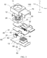
FIG. 3 is a partial exploded view of a camera module according to an embodiment of this application. -
FIG. 4 is a schematic diagram of assembly of a first driving assembly, a second driving assembly, and a support plate of a camera module according to an embodiment of this application. -
FIG. 5 is a cross-sectional view along A-A inFIG. 2 . -
FIG. 6 is a cross-sectional view along B-B inFIG. 2 . -
-
camera module 100; -
housing 10;accommodation cavity 11;holder 12;cover plate 13; -
lens assembly 20; -
circuit board 30;first board body 31;second board body 32; -
support plate 40;main board 41;side plate 42; -
first driving assembly 50; firstmagnetic member 51;first coil 52;coil 521; -
second driving assembly 60; secondmagnetic member 61;second coil 62; - flexible printed circuit
board receiving portion 70; - first
position feedback element 80; -
cross support shaft 1;Hall sensing element 2;coil 3; andmagnet 4. - Embodiments of this application are described in detail below, and examples of the embodiments are shown in accompanying drawings, where the same or similar elements or the elements having same or similar functions are denoted by the same or similar reference numerals throughout the description. The embodiments that are described with reference to the accompanying drawings are exemplary, and are only used to interpret this application, instead limiting this application. All other embodiments obtained by a person of ordinary skill in the art based on the embodiments of this application without creative efforts shall fall within the protection scope of this application.
- In the specification and claims of this application, a feature defined to be "first" or "second" may explicitly or implicitly include one or more features. In the description of this application, unless otherwise stated, the meaning of "a plurality of" is two or more than two. In addition, in this specification and the claims, "and/or" represents at least one of the connected objects, and the character "/" generally indicates an "or" relationship between the associated objects.
- In the description of this application, it should be understood that, orientations or position relationships indicated by terms such as "center", "longitudinal", "transverse", "length", "width", "thickness", "up", "down", "front", "back", "left", "right", "vertical", "horizontal", "top", "bottom", "inner", "outer", "clockwise", "counterclockwise", "axial", "radial", and "circumferential" are orientations or position relationship shown based on the accompanying drawings, and are merely used for describing this application and simplifying the description, rather than indicating or implying that the apparatus or element should have a particular orientation or be constructed and operated in a particular orientation, and therefore, should not be construed as a limitation on this application.
- In the description of this application, it should be noted that, unless explicitly specified or limited otherwise, the terms "mount", "interconnect", and "connect" should be understood broadly, for example, the connection may be fixed connection, detachable connection, or integral connection; or the connection may be a mechanical connection or an electrical connection; or the connection may be a direct connection, an indirect connection through an intermediary, or internal communication between two components. A person of ordinary skill in the art may understand the specific meanings of the foregoing terms in this application according to specific situations.
- This application is an invention by the creator based on the following facts.
-
FIG. 1 shows an image stabilization gimbal in the related art. - As shown in
FIG. 1 , a camera module in the image stabilization gimbal according to the related art uses a dangling structure. Through the cooperation of across support shaft 1 with a connected diagonal line, an electromagnetic driving system, and aHall sensing element 2, the camera module is driven to move and the position is fed back, so as to achieve the objective of image stabilization on the module. The electromagnetic driving system includes acoil 3 and amagnet 4 cooperating with each other. - As can be seen from
FIG. 1 , a camera body is embedded in the gimbal, and the electromagnetic driving system is arranged at the outside of the camera body. To be specific, the dangling system and the driving system peculiar to the gimbal result in a large size of the overall gimbal, and lead to big troubles for structure stacking and design of the camera module. - Based on this, the inventor of this application creatively obtained the following invention through long-term research and experiments.
- A
camera module 100 according to an embodiment of this application includes: ahousing 10, alens assembly 20, acircuit board 30, and a gimbal assembly. The gimbal assembly includes: asupport plate 40, afirst driving assembly 50, and asecond driving assembly 60. - Specifically, the
housing 10 is internally provided with anaccommodation cavity 11, and thelens assembly 20 is movably arranged in theaccommodation cavity 11. Thecircuit board 30 and thelens assembly 20 are connected to each other. Thesupport plate 40 is at least partially movably arranged in theaccommodation cavity 11, and thelens assembly 20 and thecircuit board 30 are arranged on thesupport plate 40. Thefirst driving assembly 50 is arranged in thehousing 10, and at least part of the first driving assembly is connected to thesupport plate 40 to drive thesupport plate 40 to move in a first direction. Thesecond driving assembly 60 is arranged on thesupport plate 40, and at least part of the second driving assembly is connected to thesupport plate 40 to drive thesupport plate 40 to move in a second direction. - In other words, the
camera module 100 according to this embodiment of this application mainly includes ahousing 10, alens assembly 20 mounted in thehousing 10, acircuit board 30 electrically connected to thelens assembly 20, and a gimbal assembly. The gimbal assembly mainly includes asupport plate 40 that can limit thelens assembly 20 and thecircuit board 30, and afirst driving assembly 50 and asecond driving assembly 60 that can drive thesupport plate 40. Thehousing 10 is a basic component of thecamera module 100, can provide a basis for mounting other components of thecamera module 100, and protects the parts or components such as the driving assembly. In this embodiment of this application, thehousing 10 has anaccommodation cavity 11 that can accommodate thelens assembly 20. - In the specific process of photographing, the
camera module 100 may incline due to jittering, and eventually affect the photographing quality. In thecamera module 100 disclosed in this embodiment of this application, thelens assembly 20 is movable relative to thehousing 10. Thefirst driving assembly 50 and thesecond driving assembly 60 drive thelens assembly 20 to move, so as to compensate an inclination caused by jittering of thecamera module 100, thereby implementing effective image stabilization on thecamera module 100. - In this embodiment of this application, the
lens assembly 20 and thecircuit board 30 can move synchronously with thesupport plate 40, and thesupport plate 40 may serve as a reinforcement plate. Therefore, when the first drivingassembly 50 and thesecond driving assembly 60 drive thesupport plate 40 to move, thelens assembly 20 and thecircuit board 30 can move simultaneously, so as to prevent thelens assembly 20 from moving relative to thecircuit board 30 and dragging thecircuit board 30. - Compared with the solution that the electromagnetic driving system directly drives the camera body in the related art, in the
camera module 100 according to this embodiment of this application, the first drivingassembly 50 and thesecond driving assembly 60 indirectly drive thelens assembly 20 and thecircuit board 30 through thesupport plate 40. In this way, thecircuit board 30 and thelens assembly 20 can move synchronously, which prevents a flexible printed circuit board from dragging the camera body in the related art, and thelens assembly 20 according to this embodiment of this application can move farther and rotate through a larger angle. In addition, the defect that the volume of the overall structure of the camera module is large because the electromagnetic driving system is mounted on the camera body in the related art is avoided. - It should be noted that, the first driving
assembly 50 can drive thesupport plate 40 to move in the first direction, and thesecond driving assembly 60 can drive thesupport plate 40 to move in the second direction, and the first direction and the second direction may be the same direction or reverse directions, or intersect with each other. This is not limited herein. Thefirst driving assembly 50 and thesecond driving assembly 60 may simultaneously or independently operate. This is not limited herein. Types of movement of thesupport plate 40 in the first direction and/or the second direction include moving and rotation types. This is not limited herein either. Through the cooperation of the first drivingassembly 50 and thesecond driving assembly 60, thesupport plate 40 is enabled to move in a larger space range, thereby expanding movement ranges of thelens assembly 20 and thecircuit board 30. - Besides, any one of the first driving
assembly 50 and thesecond driving assembly 60 includes, but is not limited to, a motor, or may be another driving structure that can enable thesupport plate 40 to move, such as a driving motor, including a driving motor, a transmission mechanism cooperating with the driving motor, and the like. - Therefore, in the
camera module 100 according to this embodiment of this application, thesupport plate 40 is connected to thelens assembly 20 and thecircuit board 30 respectively, and the first drivingassembly 50 and thesecond driving assembly 60 cooperate with each other to drive thesupport plate 40 to move in the first direction and the second direction. When thesupport plate 40 moves, thesupport plate 40 can drive thelens assembly 20 and thecircuit board 30 to move synchronously, which can prevent thelens assembly 20 from dragging thecircuit board 30 during moving, reduce a volume of the overall structure of thecamera module 100, improve the flexibility of thesupport plate 40, and expand the movement range of thesupport plate 40. - According to an embodiment of this application, the
housing 10 includes: aholder 12 and acover plate 13. Theholder 12 is provided with anaccommodation cavity 11 with an opening on a first side, thelens assembly 20 may be arranged in theaccommodation cavity 11 and is movable relative to theholder 12, and thecircuit board 30 may be connected to thelens assembly 20 through the opening. Thecover plate 13 is arranged on the first side of theholder 12, and the first drivingassembly 50 is arranged on thecover plate 13. Optionally, a part of the first drivingassembly 50 may be arranged on thecover plate 13, and another part of the first drivingassembly 50 may be arranged on thesupport plate 40 and is movable relative to thecover plate 13. - In some specific implementations of this application, the
support plate 40 includes: amain board 41 and aside plate 42. Thelens assembly 20 and thecircuit board 30 are arranged on a first side of themain board 41, the first drivingassembly 50 is at least partially located on a second side of themain board 41. Theside plate 42 is arranged on the first side of themain board 41, and thesecond driving assembly 60 is arranged on theside plate 42. In other words, thesupport plate 40 is divided into themain board 41 and theside plate 42, to facilitate mounting of the first drivingassembly 50 and thesecond driving assembly 60. - According to an embodiment of this application, the
main board 41 and theside plate 42 are approximately perpendicular to each other. - For ease of description, it is defined in the following that the
camera module 100 is assembled in an up-down direction, a direction close to a viewer is a front side, and a direction away from the viewer is a rear side. - The
main board 41 is approximately a rectangular plate and extends in a front-rear direction. A straight line parallel to a length direction of themain board 41 is referred to as a Y axis, a straight line parallel to a width direction of themain board 41 is referred to as an X axis, and a straight line perpendicular to a plane in which themain board 41 is located is referred to as a Z axis. Each part or component of thecamera module 100 may be assembled approximately in the Z-axis direction. - As shown in
FIG. 3 , thelens assembly 20 and thecircuit board 30 are located above themain board 41, and theside plate 42 is located above themain board 41. A lower end of theside plate 42 is connected to a length side of themain board 41, and an upper end of theside plate 42 extends upward in the Z axis. The arrangement of the first drivingassembly 50 on themain board 41 can enable thesupport plate 40 to rotate around the X-axis or Y-axis direction. The arrangement of thesecond driving assembly 60 on theside plate 42 can enable thesupport plate 40 to rotate around the X-axis or Y-axis direction. - It should be noted that, the foregoing definitions of up, down, the front side, the rear side, the X axis, the Y axis, and the Z axis are merely for ease of description of position relationships or connection relationships of the components of the
camera module 100 according to the embodiments of this application, and do not constitute any limitation on the embodiments of this application. - In addition, for the same parts and components in the embodiments of this application, only one of the parts or components in the figures may be marked with a reference numeral, and the reference numeral is also applicable to the other same parts or components.
- Further, the
circuit board 30 includes: afirst board body 31 and asecond board body 32. Thefirst board body 31 is arranged between thelens assembly 20 and themain board 41, thelens assembly 20 is arranged on a first side of thefirst board body 31, and a second side of thefirst board body 31 is connected to the first side of themain board 41. Thesecond board body 32 is arranged on the first side of themain board 41, and is electrically connected to thefirst board body 31. Thesecond board body 32 may be a flexible printed circuit board, a conducting wire, or the like. As shown inFIG. 3 , thefirst board body 31 is located behind thesecond board body 32 and under thelens assembly 20. When thecircuit board 30 and themain board 41 are assembled, lower sides of thefirst board body 31 and thesecond board body 32 may be respectively connected to an upper side of themain board 41. Dividing thecircuit board 30 into thefirst board body 31 and thesecond board body 32 is conducive to the connection between thecircuit board 30 and thelens assembly 20 and the movement of thelens assembly 20 while implementing synchronous movement of thecircuit board 30 and themain board 41. - Optionally, the
first board body 31 is a printed circuit board, and thesecond board body 32 is a flexible printed circuit board. During assembly, thesecond board body 32 may be folded along an S shape. When thelens assembly 20 moves, thesecond board body 32 can synchronously expand and contract, thereby expanding the movement range of thelens assembly 20. Further, thesecond board body 32 and the first drivingassembly 50 are arranged opposite to each other, and thesecond driving assembly 60 is arranged at a periphery of thesecond board body 32. In this way, the space below and at the periphery of thesecond board body 32 can be fully used, and the defect that the size of the overall structure of thecamera module 100 is large because the first drivingassembly 50 and thesecond driving assembly 60 are placed below thelens assembly 20 is avoided. - Further, in a case that the
housing 10 further includes a flexible printed circuitboard receiving portion 70, as shown inFIG. 3 , the flexible printed circuitboard receiving portion 70 may be located in front of theholder 12. Thesecond board body 32, the first drivingassembly 50, and thesecond driving assembly 60 may all be located in the flexible printed circuitboard receiving portion 70, thereby fully using the receiving space of the flexible printed circuit board receiving portion. - According to an embodiment of this application, a shape of the
first board body 31 corresponds to a shape of a surface of a first side of thelens assembly 20, and a shape of themain board 41 corresponds to shapes of thefirst board body 31 and thesecond board body 32. This improves the stability and reliability of the overall structure when thelens assembly 20 and thecircuit board 30 move. - In some specific implementations of this application, the first driving
assembly 50 includes: a firstmagnetic member 51 and afirst coil 52. One of the firstmagnetic member 51 and thefirst coil 52 is connected to thecover plate 13, and the other of the firstmagnetic member 51 and thefirst coil 52 is connected to themain board 41. After being energized, thefirst coil 52 is movable relative to the firstmagnetic member 51 to drive themain board 41. In other words, the firstmagnetic member 51 may be arranged on thecover plate 13, and thefirst coil 52 may be arranged on themain board 41; or the firstmagnetic member 51 may be arranged on thesupport plate 40, and thefirst coil 52 may be arranged on thecover plate 13. For example, as shown inFIG. 5 , the firstmagnetic member 51 is connected to an upper end surface of thecover plate 13. Thefirst coil 52 is connected to an upper end surface of themain board 41 and a lower end surface of thesecond board body 32, and cooperates with the firstmagnetic member 51. - It should be noted that, in a case that the first driving
assembly 50 includes the firstmagnetic member 51 and thefirst coil 52, thesupport plate 40 may be of a non-magnetically conductive rigid material. When the first drivingassembly 50 operates, the firstmagnetic member 51 and thefirst coil 52 cooperate with each other. According to Fleming's left-hand rule, a force perpendicular to a magnetic field direction is generated in the energizedfirst coil 52, and themain board 41 can be controlled to move when the force acts on themain board 41. - Further, the first
magnetic member 51 has a plate-shaped structure, and is attached onto thecover plate 13. In other words, the firstmagnetic member 51 may be a flat coil, and can effectively save space. The firstmagnetic member 51 is attached onto thecover plate 13, thereby facilitating the assembly of the firstmagnetic member 51. It should be noted that, the firstmagnetic member 51 may be mounted on thecover plate 13 in another mounting manner, for example, clamping, insertion, or another detachable mounting manner. - In this embodiment of this application, the
first coil 52 are twoannular coils 521 that are spaced apart on themain board 41. In a case that there are more than twocoils 521, the balance of forces can be effectively ensured. - Referring to
FIG. 4 , for example, the twoannular coils 521 may respectively be a first annular coil and a second annular coil, and the first annular coil and the second annular coil may share a magnet. Themain board 41 may rotate around a direction by controlling energization situations of the first annular coil and the second annular coil. - In this embodiment of this application, the
second board body 32 is a folded S-shaped flexible board, and the lower end surface of thesecond board body 32 is approximately a rectangular component. Length sides of thesecond board body 32 extend in the Y-axis direction, width sides of thesecond board body 32 extend in the X-axis direction, and thesecond board body 32 may be folded approximately in the Z-axis direction. - The first annular coil and the second annular coil are located on the lower end surface of the
second board body 32, and are spaced apart in a length direction of thesecond board body 32. The first annular coil and the second annular coil both are an elliptical component that extends approximately in a width direction of thesecond board body 32. In a case that forces generated on the first annular coil and the second annular coil are the same, thesupport plate 40 rotates around the X-axis direction. In a case that the forces generated on the first annular coil and the second annular coil are different, thesupport plate 40 rotates around the Y axis. In a case that the first annular coil and the second annular coil both are turned on, the balance of forces can be ensured. - According to an embodiment of this application, the
camera module 100 further includes a firstposition feedback element 80. A movement position of themain board 41 can be fed back through the firstposition feedback element 80. The firstposition feedback element 80 may be a Hall chip, or the like. This is not limited herein. - Optionally, in a case that the
coil 521 is an annular coil, the firstposition feedback element 80 may be mounted on a hollow structure of the annular coil, thereby saving space. - In some specific implementations of this application, there are two
side plates 42. The twoside plates 42 are arranged opposite to each other on the first side of themain board 41, and eachside plate 42 is provided with onesecond driving assembly 60. In a case that themain board 41 is in a strip shape, the twoside plates 42 may be spaced apart in the width direction of themain board 41, and eachside plate 42 extends in the length direction of themain board 41. - Further, the
second driving assembly 60 includes: a secondmagnetic member 61 and asecond coil 62. One of the secondmagnetic member 61 and thesecond coil 62 is connected to theside plate 42, and the other of the secondmagnetic member 61 and thesecond coil 62 is connected to thehousing 10. After being energized, thesecond coil 62 is movable relative to the secondmagnetic member 61 to drive theside plate 42. In other words, the secondmagnetic member 61 may be arranged on theside plate 42, and thesecond coil 62 may be arranged on thehousing 10; or the secondmagnetic member 61 may be arranged on thehousing 10, and thesecond coil 62 may be arranged on theside plate 42. For example, as shown inFIG. 6 , the secondmagnetic member 61 is arranged on an inner side wall of thehousing 10, and thesecond coil 62 is arranged on a side of theside plate 42 adjacent to thesecond board body 32, and cooperates with the secondmagnetic member 61. - After being energized, the
second coil 62 is movable relative to the secondmagnetic member 61 to drive thesecond board body 32. A cooperation principle of the secondmagnetic member 61 and thesecond coil 62 is the same as a cooperation principle of the firstmagnetic member 51 and thefirst coil 52. This is not described herein again. - According to an embodiment of this application, the
camera module 100 further includes a secondposition feedback element 90. A movement position of theside plate 42 can be fed back through the secondposition feedback element 90. The secondposition feedback element 90 may be a Hall chip, or the like. This is not limited herein. - Optionally, in a case that the
second coil 62 is an annular coil, the secondposition feedback element 90 may be mounted on a hollow structure of the annular coil, thereby saving space. - It should be noted that, the first driving
assembly 50 and thesecond driving assembly 60 may operate independently, or may operate cooperatively. In a case that the first drivingassembly 50 and thesecond driving assembly 60 cooperate with each other, thesupport plate 40 can rotate around the X axis and thesupport plate 40 can rotate around the Y axis. - For example, as shown in
FIG. 4 , it is set that thefirst coil 52 is subjected to forces F1 and F2 and thesecond coil 62 is subjected to forces F3 and F4. In a case that directions ofF 1, F2, F3, and F4 are the same, thesupport plate 40 is driven to move, so that thesupport plate 40 rotates around the X axis. In a case that the directions of F1 and F3 are the same, F1 and F3 are combined into one group that is represented by [F1, F3]; and in a case that the directions of F2 and F4 are the same, F2 and F4 are combined into one group that is represented by [F2, F4]. In a case that the directions of [F1, F3] and [F2, F4] are reverse, thesupport plate 40 is driven to rotate around the Y axis. - Optionally, the second
magnetic member 61 has a plate-shaped structure, and is attached onto theside plate 42. This has advantages of facilitating assembly and saving the mounting space. - An embodiment of this application further provides an electronic device, including the
camera module 100 according to any one of the foregoing embodiments. Thelens assembly 20 may be electrically connected to themain board 41 of the electronic device through thecircuit board 30, to supply power to thelens assembly 20. - The electronic device according to this embodiment of this application may be a smart phone, a tablet computer, a wearable device, or the like. This is not limited herein.
- In the descriptions of this specification, descriptions using reference terms "an embodiment", "some embodiments", "an exemplary embodiment", "an example", "a specific example", or "some examples" mean that specific characteristics, structures, materials, or features described with reference to the embodiment or example are included in at least one embodiment or example of this application. In this specification, schematic descriptions of the foregoing terms do not necessarily point at a same embodiment or example. Moreover, the specific features, structures, materials, or characteristics described may be combined in any one or more embodiments or examples in an appropriate manner.
- Although the embodiments of this application have been shown and described, a person of ordinary skill in the art should understand that various changes, modifications, replacements and variations may be made to the embodiments without departing from the principles and spirit of this application, and the scope of this application is as defined by the appended claims and their equivalents.
Claims (12)
- A camera module, comprising:a housing, internally provided with an accommodation cavity;a lens assembly, movably arranged in the accommodation cavity;a circuit board, connected to the lens assembly; anda gimbal assembly, comprising:a support plate, wherein at least part of the support plate is movably arranged in the accommodation cavity, and the lens assembly and the circuit board are arranged on the support plate;a first driving assembly, wherein the first driving assembly is arranged on the housing, and at least part of the first driving assembly is connected to the support plate to drive the support plate to move in a first direction; anda second driving assembly, wherein the second driving assembly is arranged on the support plate, and at least part of the second driving assembly is connected to the support plate to drive the support plate to move in a second direction.
- The camera module according to claim 1, wherein the housing comprises:a holder, provided with the accommodation cavity with an opening on a first side; anda cover plate, wherein the cover plate is arranged on the first side of the holder, and the first driving assembly is arranged on the cover plate.
- The camera module according to claim 2, wherein the support plate comprises:a main board, wherein the lens assembly and the circuit board are arranged on a first side of the main board, and the first driving assembly is at least partially located on a second side of the main board; anda side plate, wherein the side plate is arranged on the first side of the main board, and the second driving assembly is arranged on the side plate.
- The camera module according to claim 3, wherein the circuit board comprises:a first board body, wherein the first board body is arranged between the lens assembly and the main board, the lens assembly is arranged on a first side of the first board body, and a second side of the first board body is connected to the first side of the main board; anda second board body, wherein the second board body is arranged on the first side of the main board, and the second board body and the first board body are electrically connected to each other.
- The camera module according to claim 4, wherein the first board body is a printed circuit board, and the second board body is a flexible printed circuit board.
- The camera module according to claim 5, wherein a shape of the first board body corresponds to a shape of a surface of a first side of the lens assembly, and a shape of the main board corresponds to shapes of the first board body and the second board body.
- The camera module according to claim 3, wherein the first driving assembly comprises a first magnetic member and a first coil, one of the first magnetic member and the first coil is connected to the cover plate, and the other of the first magnetic member and the first coil is connected to the main board, and after being energized, the first coil is movable relative to the first magnetic member to drive the main board.
- The camera module according to claim 7, wherein the first magnetic member has a plate-shaped structure, and is attached onto the cover plate.
- The camera module according to claim 4, wherein two side plates are provided, the two side plates are arranged opposite to each other on the first side of the main board, and each of the side plates is provided with one second driving assembly.
- The camera module according to claim 9, wherein the second driving assembly comprises: a second magnetic member and a second coil, wherein one of the second magnetic member and the second coil is connected to the side plate, the other of the second magnetic member and the second coil is connected to the second board body, and after being energized, the second coil is movable relative to the second magnetic member to drive the second board body.
- The camera module according to claim 10, wherein the second magnetic member has a plate-shaped structure and is attached onto the side plate.
- An electronic device, comprising the camera module according to any one of claims 1 to 11.
Applications Claiming Priority (2)
| Application Number | Priority Date | Filing Date | Title |
|---|---|---|---|
| CN202011542405.XA CN112637471B (en) | 2020-12-23 | 2020-12-23 | Camera module and electronic equipment |
| PCT/CN2021/138635 WO2022135251A1 (en) | 2020-12-23 | 2021-12-16 | Camera module and electronic device |
Publications (2)
| Publication Number | Publication Date |
|---|---|
| EP4270919A1 true EP4270919A1 (en) | 2023-11-01 |
| EP4270919A4 EP4270919A4 (en) | 2024-06-12 |
Family
ID=75321961
Family Applications (1)
| Application Number | Title | Priority Date | Filing Date |
|---|---|---|---|
| EP21909247.5A Pending EP4270919A4 (en) | 2020-12-23 | 2021-12-16 | Camera module and electronic device |
Country Status (5)
| Country | Link |
|---|---|
| US (1) | US12401873B2 (en) |
| EP (1) | EP4270919A4 (en) |
| JP (1) | JP7690032B2 (en) |
| CN (1) | CN112637471B (en) |
| WO (1) | WO2022135251A1 (en) |
Families Citing this family (3)
| Publication number | Priority date | Publication date | Assignee | Title |
|---|---|---|---|---|
| CN112637471B (en) * | 2020-12-23 | 2022-02-08 | 维沃移动通信有限公司 | Camera module and electronic equipment |
| CN112637470B (en) | 2020-12-23 | 2021-12-21 | 维沃移动通信有限公司 | Camera module and electronic equipment |
| US12184979B2 (en) | 2021-06-29 | 2024-12-31 | Avary Holding (Shenzhen) Co., Limited. | Camera module having optical image stabilization function, and preparation method therefor |
Family Cites Families (35)
| Publication number | Priority date | Publication date | Assignee | Title |
|---|---|---|---|---|
| JP2006259247A (en) * | 2005-03-17 | 2006-09-28 | Pentax Corp | Image blur correction device |
| KR100754730B1 (en) * | 2005-05-26 | 2007-09-03 | 삼성전자주식회사 | Image stabilizer in camera lens assembly |
| KR100717054B1 (en) * | 2005-11-09 | 2007-05-14 | 삼성전자주식회사 | Optical Pickup Actuator |
| JP2007312325A (en) * | 2006-05-22 | 2007-11-29 | Alps Electric Co Ltd | Apparatus preventing hand wobbling of optical equipment |
| JP5604068B2 (en) * | 2009-08-11 | 2014-10-08 | 日本電産サンキョー株式会社 | Optical unit and manufacturing method thereof |
| JP5828686B2 (en) * | 2010-09-07 | 2015-12-09 | 日本電産サンキョー株式会社 | Optical unit with shake correction function |
| KR101330202B1 (en) * | 2011-05-06 | 2013-11-15 | 도시바삼성스토리지테크놀러지코리아 주식회사 | Objective Lens Driving Unit and Optical Pickup Device adopting the Unit |
| JP2013140284A (en) | 2012-01-05 | 2013-07-18 | Sony Corp | Image-blurring correction device and imaging apparatus |
| US9372352B2 (en) * | 2013-08-23 | 2016-06-21 | Samsung Electro-Mechanics Co., Ltd. | Lens driving device and camera module including the same |
| JP6507628B2 (en) * | 2014-12-24 | 2019-05-08 | ミツミ電機株式会社 | Actuator, camera module and camera mounted device |
| CN107615160B (en) * | 2015-05-29 | 2020-06-16 | 三美电机株式会社 | Actuator, camera module, and camera-mounted device |
| US10859890B2 (en) * | 2015-06-30 | 2020-12-08 | Lg Innotek Co., Ltd. | Lens moving apparatus, and camera module and portable device including same |
| CN105573014A (en) * | 2016-01-22 | 2016-05-11 | 南昌欧菲光电技术有限公司 | Camera module with focusing and anti-shaking functions |
| KR101700771B1 (en) * | 2016-05-04 | 2017-01-31 | 엘지전자 주식회사 | Mobile terminal |
| KR102507054B1 (en) * | 2016-05-18 | 2023-03-07 | 삼성전자주식회사 | Camera and electronic device including the same |
| US10663751B2 (en) * | 2016-06-16 | 2020-05-26 | Fotonation Limited | Gimbal adjustment system |
| CN108401093B (en) * | 2017-02-08 | 2024-03-08 | 宁波舜宇光电信息有限公司 | Image pickup module, molded photosensitive assembly thereof, manufacturing method of molded photosensitive assembly and electronic equipment |
| JP2019082454A (en) * | 2017-10-31 | 2019-05-30 | セイコーエプソン株式会社 | Gyro sensor device, attitude control system, and camera device |
| JP2019083488A (en) * | 2017-10-31 | 2019-05-30 | キヤノン株式会社 | Imaging device, support device, method of controlling them, and program |
| EP3848749A1 (en) * | 2018-02-05 | 2021-07-14 | Corephotonics Ltd. | Reduced height penalty for folded camera |
| JP7222629B2 (en) * | 2018-08-06 | 2023-02-15 | 日本電産サンキョー株式会社 | optical unit |
| CN208509085U (en) * | 2018-08-23 | 2019-02-15 | Oppo广东移动通信有限公司 | A kind of camera module and electronic equipment |
| US11347074B2 (en) * | 2018-11-30 | 2022-05-31 | Nidec Sankyo Corporation | Optical unit having shake correction function |
| US11300802B2 (en) * | 2018-11-30 | 2022-04-12 | Nidec Sankyo Corporation | Optical unit |
| CN111385446B (en) * | 2018-12-27 | 2025-11-21 | 华为技术有限公司 | Camera assembly and user equipment |
| JP7269774B2 (en) | 2019-03-28 | 2023-05-09 | ニデックインスツルメンツ株式会社 | Optical unit with shake correction function, wiring member, and manufacturing method thereof |
| CN112055102B (en) * | 2019-06-06 | 2021-10-15 | 华为技术有限公司 | A camera module, video camera and mobile terminal |
| JP2021139988A (en) * | 2020-03-04 | 2021-09-16 | 日本電産サンキョー株式会社 | Optical unit with runout correction function |
| CN111474804B (en) * | 2020-05-07 | 2022-05-20 | Oppo广东移动通信有限公司 | Imaging device and electronic apparatus |
| CN211880480U (en) * | 2020-05-07 | 2020-11-06 | Oppo广东移动通信有限公司 | Imaging devices and electronic equipment |
| CN111726508A (en) * | 2020-07-06 | 2020-09-29 | 瑞声新能源发展(常州)有限公司科教城分公司 | Lens module |
| CN112637470B (en) * | 2020-12-23 | 2021-12-21 | 维沃移动通信有限公司 | Camera module and electronic equipment |
| CN112637471B (en) * | 2020-12-23 | 2022-02-08 | 维沃移动通信有限公司 | Camera module and electronic equipment |
| CN112637469B (en) * | 2020-12-23 | 2022-04-15 | 维沃移动通信有限公司 | Camera module and electronic equipment |
| CN117119283A (en) * | 2023-08-30 | 2023-11-24 | 华为技术有限公司 | Photosensitive components, camera modules and electronic equipment |
-
2020
- 2020-12-23 CN CN202011542405.XA patent/CN112637471B/en active Active
-
2021
- 2021-12-16 WO PCT/CN2021/138635 patent/WO2022135251A1/en not_active Ceased
- 2021-12-16 JP JP2023538153A patent/JP7690032B2/en active Active
- 2021-12-16 EP EP21909247.5A patent/EP4270919A4/en active Pending
-
2023
- 2023-06-22 US US18/340,010 patent/US12401873B2/en active Active
Also Published As
| Publication number | Publication date |
|---|---|
| JP2024500913A (en) | 2024-01-10 |
| US20230336857A1 (en) | 2023-10-19 |
| JP7690032B2 (en) | 2025-06-09 |
| EP4270919A4 (en) | 2024-06-12 |
| CN112637471B (en) | 2022-02-08 |
| CN112637471A (en) | 2021-04-09 |
| US12401873B2 (en) | 2025-08-26 |
| WO2022135251A1 (en) | 2022-06-30 |
Similar Documents
| Publication | Publication Date | Title |
|---|---|---|
| US12401873B2 (en) | Camera module and electronic device | |
| EP3373562B1 (en) | Terminal having camera module | |
| EP4270920B1 (en) | Camera module, and electronic device | |
| US12439137B2 (en) | Camera module and electronic device | |
| CN112799202A (en) | Lens module | |
| CN113489887B (en) | Anti-shake mechanism, imaging device, and electronic apparatus | |
| CN106773105A (en) | A kind of parallel-moving type optical anti-vibration lens driver | |
| CN111740561A (en) | Lens drive mechanism, lens drive device, camera device, electronic product | |
| CN114257710B (en) | Optical anti-shake structure and camera modules and terminal equipment having the same | |
| CN114666486B (en) | Camera module and electronic equipment | |
| CN217825083U (en) | Camera module and electronic equipment | |
| CN214252704U (en) | Lens module | |
| CN113099086B (en) | Camera units and electronics | |
| CN219227384U (en) | Lens driving mechanism and base thereof | |
| CN113079294B (en) | Camera device and electronic equipment | |
| CN115278028B (en) | Camera module and electronic equipment | |
| CN223829391U (en) | Camera module and electronic equipment | |
| CN219225274U (en) | Lens driving mechanism and circuit board thereof | |
| EP4617757A1 (en) | Sliding focusing driving device, lens module, and electronic device | |
| CN119233052B (en) | Actuators, camera modules and electronic devices | |
| US20250365493A1 (en) | Image sensing device | |
| CN215344339U (en) | Novel OIS motor | |
| WO2026001586A1 (en) | Foldable circuit board structure, anti-shake gimbal, camera device and electronic apparatus | |
| CN220798432U (en) | Camera module and electronic equipment | |
| CN121888075A (en) | Camera module and electronic equipment |
Legal Events
| Date | Code | Title | Description |
|---|---|---|---|
| STAA | Information on the status of an ep patent application or granted ep patent |
Free format text: STATUS: THE INTERNATIONAL PUBLICATION HAS BEEN MADE |
|
| PUAI | Public reference made under article 153(3) epc to a published international application that has entered the european phase |
Free format text: ORIGINAL CODE: 0009012 |
|
| STAA | Information on the status of an ep patent application or granted ep patent |
Free format text: STATUS: REQUEST FOR EXAMINATION WAS MADE |
|
| 17P | Request for examination filed |
Effective date: 20230721 |
|
| AK | Designated contracting states |
Kind code of ref document: A1 Designated state(s): AL AT BE BG CH CY CZ DE DK EE ES FI FR GB GR HR HU IE IS IT LI LT LU LV MC MK MT NL NO PL PT RO RS SE SI SK SM TR |
|
| DAV | Request for validation of the european patent (deleted) | ||
| DAX | Request for extension of the european patent (deleted) | ||
| REG | Reference to a national code |
Ref country code: DE Ref legal event code: R079 Free format text: PREVIOUS MAIN CLASS: H04N0005225000 Ipc: H04N0023000000 |
|
| A4 | Supplementary search report drawn up and despatched |
Effective date: 20240510 |
|
| RIC1 | Information provided on ipc code assigned before grant |
Ipc: H04N 23/00 20230101AFI20240503BHEP |
|
| STAA | Information on the status of an ep patent application or granted ep patent |
Free format text: STATUS: EXAMINATION IS IN PROGRESS |
|
| 17Q | First examination report despatched |
Effective date: 20250715 |