EP4270831A1 - Method and device for repeatedly transmitting data channel - Google Patents
Method and device for repeatedly transmitting data channel Download PDFInfo
- Publication number
- EP4270831A1 EP4270831A1 EP20967454.8A EP20967454A EP4270831A1 EP 4270831 A1 EP4270831 A1 EP 4270831A1 EP 20967454 A EP20967454 A EP 20967454A EP 4270831 A1 EP4270831 A1 EP 4270831A1
- Authority
- EP
- European Patent Office
- Prior art keywords
- data channel
- repetition factor
- res
- slot
- slot repetition
- Prior art date
- Legal status (The legal status is an assumption and is not a legal conclusion. Google has not performed a legal analysis and makes no representation as to the accuracy of the status listed.)
- Pending
Links
Images
Classifications
-
- H—ELECTRICITY
- H04—ELECTRIC COMMUNICATION TECHNIQUE
- H04W—WIRELESS COMMUNICATION NETWORKS
- H04W72/00—Local resource management
- H04W72/12—Wireless traffic scheduling
- H04W72/1263—Mapping of traffic onto schedule, e.g. scheduled allocation or multiplexing of flows
-
- H—ELECTRICITY
- H04—ELECTRIC COMMUNICATION TECHNIQUE
- H04L—TRANSMISSION OF DIGITAL INFORMATION, e.g. TELEGRAPHIC COMMUNICATION
- H04L1/00—Arrangements for detecting or preventing errors in the information received
- H04L1/08—Arrangements for detecting or preventing errors in the information received by repeating transmission, e.g. Verdan system
-
- H—ELECTRICITY
- H04—ELECTRIC COMMUNICATION TECHNIQUE
- H04L—TRANSMISSION OF DIGITAL INFORMATION, e.g. TELEGRAPHIC COMMUNICATION
- H04L1/00—Arrangements for detecting or preventing errors in the information received
- H04L1/004—Arrangements for detecting or preventing errors in the information received by using forward error control
- H04L1/0041—Arrangements at the transmitter end
-
- H—ELECTRICITY
- H04—ELECTRIC COMMUNICATION TECHNIQUE
- H04L—TRANSMISSION OF DIGITAL INFORMATION, e.g. TELEGRAPHIC COMMUNICATION
- H04L1/00—Arrangements for detecting or preventing errors in the information received
- H04L1/004—Arrangements for detecting or preventing errors in the information received by using forward error control
- H04L1/0056—Systems characterized by the type of code used
- H04L1/0057—Block codes
-
- H—ELECTRICITY
- H04—ELECTRIC COMMUNICATION TECHNIQUE
- H04L—TRANSMISSION OF DIGITAL INFORMATION, e.g. TELEGRAPHIC COMMUNICATION
- H04L1/00—Arrangements for detecting or preventing errors in the information received
- H04L1/12—Arrangements for detecting or preventing errors in the information received by using return channel
- H04L1/16—Arrangements for detecting or preventing errors in the information received by using return channel in which the return channel carries supervisory signals, e.g. repetition request signals
- H04L1/18—Automatic repetition systems, e.g. Van Duuren systems
-
- H—ELECTRICITY
- H04—ELECTRIC COMMUNICATION TECHNIQUE
- H04L—TRANSMISSION OF DIGITAL INFORMATION, e.g. TELEGRAPHIC COMMUNICATION
- H04L1/00—Arrangements for detecting or preventing errors in the information received
- H04L1/12—Arrangements for detecting or preventing errors in the information received by using return channel
- H04L1/16—Arrangements for detecting or preventing errors in the information received by using return channel in which the return channel carries supervisory signals, e.g. repetition request signals
- H04L1/18—Automatic repetition systems, e.g. Van Duuren systems
- H04L1/1812—Hybrid protocols; Hybrid automatic repeat request [HARQ]
- H04L1/1819—Hybrid protocols; Hybrid automatic repeat request [HARQ] with retransmission of additional or different redundancy
-
- H—ELECTRICITY
- H04—ELECTRIC COMMUNICATION TECHNIQUE
- H04L—TRANSMISSION OF DIGITAL INFORMATION, e.g. TELEGRAPHIC COMMUNICATION
- H04L1/00—Arrangements for detecting or preventing errors in the information received
- H04L1/12—Arrangements for detecting or preventing errors in the information received by using return channel
- H04L1/16—Arrangements for detecting or preventing errors in the information received by using return channel in which the return channel carries supervisory signals, e.g. repetition request signals
- H04L1/18—Automatic repetition systems, e.g. Van Duuren systems
- H04L1/1829—Arrangements specially adapted for the receiver end
- H04L1/1864—ARQ related signaling
-
- H—ELECTRICITY
- H04—ELECTRIC COMMUNICATION TECHNIQUE
- H04L—TRANSMISSION OF DIGITAL INFORMATION, e.g. TELEGRAPHIC COMMUNICATION
- H04L1/00—Arrangements for detecting or preventing errors in the information received
- H04L1/12—Arrangements for detecting or preventing errors in the information received by using return channel
- H04L1/16—Arrangements for detecting or preventing errors in the information received by using return channel in which the return channel carries supervisory signals, e.g. repetition request signals
- H04L1/18—Automatic repetition systems, e.g. Van Duuren systems
- H04L1/1867—Arrangements specially adapted for the transmitter end
- H04L1/1896—ARQ related signaling
-
- H—ELECTRICITY
- H04—ELECTRIC COMMUNICATION TECHNIQUE
- H04W—WIRELESS COMMUNICATION NETWORKS
- H04W72/00—Local resource management
- H04W72/04—Wireless resource allocation
- H04W72/044—Wireless resource allocation based on the type of the allocated resource
- H04W72/0446—Resources in time domain, e.g. slots or frames
-
- H—ELECTRICITY
- H04—ELECTRIC COMMUNICATION TECHNIQUE
- H04L—TRANSMISSION OF DIGITAL INFORMATION, e.g. TELEGRAPHIC COMMUNICATION
- H04L1/00—Arrangements for detecting or preventing errors in the information received
- H04L1/0001—Systems modifying transmission characteristics according to link quality, e.g. power backoff
- H04L1/0002—Systems modifying transmission characteristics according to link quality, e.g. power backoff by adapting the transmission rate
- H04L1/0003—Systems modifying transmission characteristics according to link quality, e.g. power backoff by adapting the transmission rate by switching between different modulation schemes
-
- H—ELECTRICITY
- H04—ELECTRIC COMMUNICATION TECHNIQUE
- H04L—TRANSMISSION OF DIGITAL INFORMATION, e.g. TELEGRAPHIC COMMUNICATION
- H04L1/00—Arrangements for detecting or preventing errors in the information received
- H04L1/0001—Systems modifying transmission characteristics according to link quality, e.g. power backoff
- H04L1/0009—Systems modifying transmission characteristics according to link quality, e.g. power backoff by adapting the channel coding
-
- H—ELECTRICITY
- H04—ELECTRIC COMMUNICATION TECHNIQUE
- H04L—TRANSMISSION OF DIGITAL INFORMATION, e.g. TELEGRAPHIC COMMUNICATION
- H04L5/00—Arrangements affording multiple use of the transmission path
- H04L5/0001—Arrangements for dividing the transmission path
- H04L5/0003—Two-dimensional division
- H04L5/0005—Time-frequency
-
- H—ELECTRICITY
- H04—ELECTRIC COMMUNICATION TECHNIQUE
- H04L—TRANSMISSION OF DIGITAL INFORMATION, e.g. TELEGRAPHIC COMMUNICATION
- H04L5/00—Arrangements affording multiple use of the transmission path
- H04L5/003—Arrangements for allocating sub-channels of the transmission path
- H04L5/0044—Allocation of payload; Allocation of data channels, e.g. PDSCH or PUSCH
Definitions
- the embodiments of the present disclosure relate to a field of communication technology, and more particularly, to a method and device for repeatedly transmitting data channel.
- a network device can configure a terminal device to use multi-slot repeated transmission to improve transmission coverage.
- TBS Transport Block Size
- OFDM Orthogonal Frequency-Division Multiplexing
- the present disclosure provides a method and device for repeatedly transmitting data channel, capable of improving resource utilization.
- a method for repeatedly transmitting data channel includes: determining a transport block size corresponding to the data channel according to a first slot repetition factor and/or a number of time-domain symbols in slots for repeated transmission of the data channel; obtaining encoded information bits by encoding the data channel according to the transport block size corresponding to the data channel; and mapping the encoded information bits onto a plurality of slots.
- a device for repeatedly transmitting data channel is provided.
- the device is configured to perform the method according to the above first aspect or any implementation thereof.
- the device includes one or more functional modules configured to perform the method according to the above first aspect or any implementation thereof.
- a device for repeatedly transmitting data channel includes a processor and a memory.
- the memory has a computer program stored thereon, and the processor is configured to invoke and execute the computer program stored in the memory to perform the method according to the above first aspect or any implementation thereof.
- a chip is provided.
- the chip is configured to perform the method according to any of the above first aspect or any implementation thereof.
- the chip includes a processor configured to invoke and execute a computer program from a memory, to cause a device provided with the apparatus to perform the method according to any of the above first aspect or any implementation thereof.
- a computer-readable storage medium stores a computer program that causes a computer to perform the method according to any of the above first aspect or any implementation thereof.
- a computer program product includes computer program instructions that cause a computer to perform the method according to any of the above first aspect or any implementation thereof.
- a computer program when executed on a computer, causes the computer to perform the method according to any of the above first aspect or any implementation thereof.
- a TBS when a second slot repetition factor is configured, a TBS can be determined according to a first slot repetition factor and/or a number of time-domain symbols in slots actually used for repeated transmission of the data channel. This is equivalent to considering time-domain symbol allocation across multiple slots to calculate the TBS, such that the size of the calculated TBS can be increased. Further, in order to obtain a same bit rate, only a small number of PRBs need to be allocated, thereby improving resource utilization.
- GSM Global System of Mobile Communication
- CDMA Code Division Multiple Access
- WCDMA Wideband Code Division Multiple Access
- GPRS General Packet Radio Service
- LTE Long Term Evolution
- LTE-A Advanced Long Term Evolution
- NR New Radio
- NTN Non-Terrestrial Network
- UMTS Universal Mobile Telecommunication System
- WLAN Wireless Local Area Networks
- WiFi Wireless Fidelity
- D2D Device to Device
- M2M Machine to Machine
- MTC Machine Type Communication
- V2V Vehicle to Vehicle
- V2X Vehicle to everything
- the communication system of an embodiment of the present disclosure may be applied to a Carrier Aggregation (CA) scenario, a Dual Connectivity (DC) scenario, a Standalone (SA) network deployment scenario, and the like.
- CA Carrier Aggregation
- DC Dual Connectivity
- SA Standalone
- the communication system of an embodiment of the present disclosure may be applied to unlicensed spectrum or shared spectrum.
- the communication system of an embodiment of the present disclosure may be applied to licensed spectrum or non-shared spectrum.
- the embodiments of the present disclosure are described in conjunction with a network device and a terminal device.
- the terminal device may refer to a User Equipment (UE), an access terminal, a user unit, a user station, a mobile station, a remote station, a remote terminal, a mobile device, a user terminal, a terminal, a wireless communication device, a user agent, or a user device.
- UE User Equipment
- the terminal device may be a station (ST) in a WLAN, a cellular phone, a cordless phone, a Session Initiation Protocol (SIP) phone, a Wireless Local Loop (WLL) station, a Personal Digital Assistant (PDA) device, a handheld device having a wireless communication function, a computing device, another processing device connected to a wireless modem, a vehicle-mounted device, a wearable device, a terminal device in the next generation communication system (e.g., NR network), or a terminal device in a future evolved Public Land Mobile Network (PLMN), etc.
- ST station
- WLAN Wireless Local Loop
- PDA Personal Digital Assistant
- the terminal device can be deployed on land, including indoor or outdoor, handheld, worn, or vehicle-mounted, deployed on water (e.g., on a ship), or deployed in the air (e.g., on an airplane, a balloon, a satellite, etc.).
- the terminal device may be a mobile phone, a tablet computer (Pad), a computer with a wireless transceiver function, a Virtual Reality (VR) terminal device, an Augmented Reality (AR) terminal device, a wireless terminal in industrial control, a wireless terminal device in self driving, a wireless terminal device in remote medical, a wireless terminal device in smart grid, a wireless terminal device in transportation safety, a wireless terminal device in smart city, or a wireless terminal device in smart home.
- a mobile phone a tablet computer (Pad), a computer with a wireless transceiver function
- a Virtual Reality (VR) terminal device an Augmented Reality (AR) terminal device
- a wireless terminal in industrial control a wireless terminal device in self driving
- a wireless terminal device in remote medical a wireless terminal device in smart grid, a wireless terminal device in transportation safety, a wireless terminal device in smart city, or a wireless terminal device in smart home.
- the terminal device may also be a wearable device.
- the wearable device also known as wearable smart device, is a general term for wearable devices that are intelligently designed and developed from everyday wear, such as glasses, gloves, watches, clothes, and shoes, by applying wearable technologies.
- a wearable device is a portable device that can be directly worn on or integrated into a user's clothes or accessories.
- a wearable device is not only a kind of hardware device, but can also provide powerful functions based on software support, data interaction, and cloud interaction.
- wearable smart devices may include full-featured, large-sized devices that can provide full or partial functions without relying on smart phones, such as smart watches or smart glasses, and devices that only focus on a certain type of application function and need to cooperate with other devices such as smart phones for use, such as various smart bracelets and smart jewelries for physical sign monitoring.
- the network device may be a device communicating with mobile devices.
- the network device may be an Access Point (AP) in a WLAN, a base station such as Base Transceiver Station (BTS) in a GSM system or a CDMA system, a base station such as NodeB (NB) in a WCDMA system, a base station such as Evolutional Node (eNB or eNodeB) in an LTE system, or a relay station, an access point, a vehicle-mounted device, a wearable device, a network device or base station (e.g., gNB) in an NR network, a network device in a future evolved PLMN, or a network device in an NTN.
- AP Access Point
- BTS Base Transceiver Station
- NB NodeB
- eNB Evolutional Node
- LTE Long Term Evolutional Node
- the network device may have mobile characteristics, e.g., the network device may be a mobile device.
- the network device may be a satellite or a balloon station.
- the satellite may be a Low Earth Orbit (LEO) satellite, a Medium Earth Orbit (MEO) satellite, a Geostationary Earth Orbit (GEO) satellite, a High Elliptical Orbit (HEO) satellite, etc.
- the network device may also be a base station provided in a location such as land or water.
- the network device may provide services for a cell, and the terminal device may communicate with the network device over transmission resources, e.g., frequency domain resources or frequency spectral resources, used in the cell.
- the cell may be a cell corresponding to the network device (e.g., base station).
- the cell may belong to a macro base station or a base station corresponding to a small cell.
- the small cell here may include a metro cell, a micro cell, a pico cell, a femto cell, or the like. These small cells have characteristics such as small coverage and low transmission power, and are suitable for providing high-rate data transmission services.
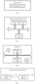
- FIG. 1 shows an architecture of a communication system 100 where an embodiment of the present disclosure can be applied.
- the communication system 100 may include a network device 110 which may be a device communicating with a terminal device 120 (or referred to as communication terminal or terminal).
- the network device 110 may provide communication coverage for a particular geographic area, and may communicate with terminal devices located within the coverage.
- FIG. 1 exemplarily shows one network device and two terminal devices.
- the communication system 100 may include multiple network devices, and the coverage of each network device may include other numbers of terminal devices.
- the embodiment of the present disclosure is not limited to this.
- the wireless communication system 100 may also include other network entities such as a network controller or a Mobility Management Entity (MME).
- MME Mobility Management Entity
- a device having a communication function in a network/system may be referred to as a communication device.
- the communication devices may include the network device 110 and the terminal device 120 with communication functions.
- the network device 110 and the terminal device 120 may be the specific devices described above, and details thereof will be omitted here.
- the communication devices may also include other devices in the communication system 100, e.g., other network entities such as a network controller, an MME, etc., and the embodiment of the present disclosure is not limited to any of these examples.
- system and “network” may often be used interchangeably herein.
- the term “and/or” as used herein only represents a relationship between correlated objects, including three relationships.
- a and/or B may mean A only, B only, or both A and B.
- the symbol “/” as used herein represents an “or” relationship between the correlated objects preceding and succeeding the symbol.
- indication may be a direct indication, an indirect indication, or an association.
- a indicates B it may mean that A directly indicates B, e.g., B can be obtained from A.
- a indicates B indirectly e.g., A indicates C and B can be obtained from C.
- the term "corresponding" may mean that there is a direct or indirect correspondence between the two, or may mean that there is an association between the two, or that they are in a relation of indicating and indicated, configuring or configured, or the like.
- predefined may implemented as pre-stored in one or more devices (for example, including a terminal device and a network device) corresponding codes, tables or other means that can be used to indicate related information, and the present disclosure is not limited to its specific implementation.
- predefined may refer to defined in protocols.
- protocols may refer to standard protocols in the communication field, including e.g., the LTE protocol, the NR protocol, and related protocols applied in future communication systems.
- the present disclosure is not limited to any of these examples.
- multi-slot PUSCH and PDSCH transmissions can be performed with uplink and downlink aggregation factors.
- a terminal device can improve the coverage of a single transmission by means of multi-slot repeated transmission.
- the same Demodulation Reference Signal (DMRS) time domain structure is used in each slot when a PUSCH/PDSCH transmission is repeated.
- DMRS Demodulation Reference Signal
- the NR system supports flexible slot ratio.
- a slot can have some uplink time-domain symbols and some time-domain symbols.
- Physical Uplink Control Channel (PUCCH) and Physical Uplink Shared Channel (PUSCH) are only transmitted in the uplink time-domain symbols
- Physical Downlink Control Channel (PDCCH) and Physical Downlink Shared Channel (PDSCH) are only transmitted in the uplink time-domain symbols.
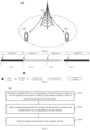
- FIG. 2 shows a schematic diagram of multi-slot repeated transmission.
- the symbol configurations in Slot 1 and Slot 2 are basically downlink time-domain symbols, the number of uplink time-domain symbols does not meet the transmission requirements. Therefore, the terminal device omits transmission in Slot 1 and Slot 2, and performs repeated transmission in Slot 0 and Slot 3 only. Therefore, when the terminal device is configured to perform four repeated transmissions, the terminal device actually performs only two repeated transmissions.
- TBS Transport Block Size
- this method for determining the TBS may cause the determined TBS to be too large or too small, and in coverage-limited cases, in order to obtain a specific bit rate, more Physical Resource Blocks (PRBs) need to be allocated, resulting in degraded resource utilization. Therefore, how to determine the TBS size in the multi-slot repeated transmission to improve resource utilization is a problem to be solved.
- PRBs Physical Resource Blocks
- FIG. 3 is a schematic flowchart illustrating a method 300 for repeatedly transmitting data channel according to an embodiment of the present disclosure.
- the method 300 can be performed by a terminal device or a network device in the communication system shown in FIG. 1 .
- the embodiments of the present disclosure will be described where the method is performed by a terminal device, and the actions of the network devices will be similar, so for the sake of brevity, details thereof will be omitted.
- the method 300 includes the following content.
- a transport block size corresponding to the data channel is determined according to a first slot repetition factor and/or a number of time-domain symbols in slots for repeated transmission of the data channel.
- encoded information bits are obtained by encoding the data channel according to the transport block size corresponding to the data channel.
- the encoded information bits are mapped onto a plurality of slots.
- the embodiments of the present disclosure may be applicable to determining a TBS for a data channel, or may be applicable to determining a TBS for another channel, such as a control channel, etc., and the present disclosure is not limited to this.
- the data channel may be an uplink data channel, such as a Physical Uplink Shared channel (PUSCH), or may be a downlink data channel, such as a Physical Downlink Shared Channel (PDSCH).
- PUSCH Physical Uplink Shared channel
- PDSCH Physical Downlink Shared Channel
- the time-domain symbols may refer to OFDM symbols, and a number of time-domain symbols may refer to the number of OFDM symbols.
- the terminal device may determine the TBS for the data channel according to the first slot repetition factor and/or the number of time-domain symbols in the slots for repeated transmission of the data channel when the terminal device is configured with a second slot repetition factor.
- the second slot repetition factor may indicate a number of slots for repeated transmission of the data channel.
- the second slot repetition factor may be configured by a network device.
- the network device may configure the second slot repetition factor via Radio Resource Control (RRC) signaling or other signaling, and the present disclosure is not limited to this.
- RRC Radio Resource Control
- the second slot repetition factor may correspond to the aggregation factor as described above.
- the number of slots for the terminal device to repeatedly transmit the data channel may be determined according to the second slot repetition factor, that is, the number of slots may be determined according to the second slot repetition factor.
- the number of time-domain symbols in the slots for repeated transmission of the data channel may refer to a number of time-domain symbols in the slots actually used for repeated transmission of the data channel.
- the embodiment of the present disclosure determines the TBS according to the number of time-domain symbols in the slots actually used for repeated transmission of the data channel, so as to dynamically determine the number of time-domain symbols used to transmit the data channel according to the flexible slot structure, and further dynamically determine the TBS corresponding to the data channel, thereby achieving better scheduling of TBs in the multi-slot repetition scenario, and ensuring coverage performance of the TBs.
- the first slot repetition factor may be smaller than or equal to the second slot repetition factor.
- the first slot repetition factor may be determined according to the second slot repetition factor.
- the first slot repetition factor may be the second slot repetition factor multiplied by a first coefficient, the first coefficient being a positive number smaller than or equal to 1.
- the first slot repetition factor may be configured by a network device.
- the network device may configure the first slot repetition factor via a downlink message or signaling such as RRC signaling or Downlink Control Information (DCI).
- a downlink message or signaling such as RRC signaling or Downlink Control Information (DCI).
- DCI Downlink Control Information
- the first slot repetition factor may be determined according to the number of slots actually used for repeated transmission of the data channel. For example, in the example shown in FIG. 2 , the second slot repetition factor is 4, and the number of slots used for multi-slot transmission is 2, then the first slot repetition factor may be 2.
- S310 may include: determining the transport block size corresponding to the data channel according to the first slot repetition factor and a scheduling parameter.
- the scheduling parameter may include at least one of: a target number of Resource Elements (REs) N RE , a coding rate R , a modulation order Q m , or a number of transmission layers ⁇ .
- REs Resource Elements
- the scheduling parameter may be included in Downlink Control Information (DCI) scheduling the data channel.
- DCI Downlink Control Information
- the operation of determining the transport block size corresponding to the data channel according to the first slot repetition factor and the scheduling parameter may include:
- the first reference RE number threshold may be 156, or other values, and the present disclosure is not limited to this.
- DMRS Demodulation Reference Signal
- N sc RB , N symb sh , and N DMRS PRB can be obtained from the scheduling information carried by the DCI.
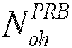
- N oh PRB may be configured by a network device, or may be a fixed value.
- X may be a positive integer greater than 1, that is, the first slot repetition factor is a positive integer.
- the TBS corresponding to the data channel is calculated according to Equation (1), i.e., the TBS is calculated while considering the OFDM symbol allocations in multiple slots, which can increase the size of the calculated TBS. Further, in order to obtain a same bit rate, only a small number of PRBs need to be allocated, thereby improving resource utilization.
- the operation of determining the intermediate number of information bits according to the first slot repetition factor and the scheduling parameter may include:
- the operation of determining the target number, N RE , of REs according to the first slot repetition factor includes: determining the target number, N RE , of REs according to the first slot repetition factor X and a reference number, N RE ′ , of available REs in one slot.
- the first reference RE number threshold may be 156, or other values, and the present disclosure is not limited to this.
- the terminal device may determine the reference number, N RE ′ , of available REs in the one slot according to the above Equation (3).
- the target number, N RE of REs can be calculated according to Equation (4), i.e., the target number of REs can be calculated according to the first slot repetition factor. That is, the TBS is calculated while considering the OFDM symbol allocations in multiple slots, which can increase the size of the calculated TBS. Further, in order to obtain a same bit rate, only a small number of PRBs need to be allocated, thereby improving resource utilization.
- the operation determining the target number, N RE , of REs according to the first slot repetition factor may include:
- the number of time-domain symbols in the slots for repeated transmission of the data channel may refer to the number of available time-domain symbols in the slots for actually transmitting the data channel, or the number of time-domain symbols actually used for transmitting the data channel in the slots for actually transmitting the data channel.
- the TBS is determined by considering the number of time-domain symbols in the slots actually used for repeated transmission of the data channel, such that the number of time-domain symbols used for transmission of the data channel can be dynamically determined according to the flexible slot structure, which is capable of overcoming the problem in the related art that the TBS determined according to the number of time-domain symbols in one single slot may be too large or too small. Since the TBS is determined by considering the number of time-domain symbols in multiple slots, the size of the calculated TBS can be increased. Further, in order to obtain a same bit rate, only a small number of PRBs need to be allocated, thereby improving resource utilization.
- the TBS while considering the number of time-domain symbols in the slots for actually transmitting the data channel, it can be more accurately applied to the adaptive repeated transmission of the data channel with the flexible slot structure, and better solve the problem of insufficient coverage of the data channel.
- the terminal device may determine the reference number, N RE " , of available REs in the slots for repeated transmission of the data channel according to the following Equation (6):
- X represents the first slot repetition factor
- N sc RB represents a number of subcarriers on each RB
- N symb i sh represents a number of time-domain symbols in the i-th slot for repeated transmission of the data channel
- N DMRS , i PRB represents a number of REs occupied by a DMRS in each RB in the i-th slot for repeated transmission of the data channel
- N oh PRB represents a number of overhead REs.
- N RE " is determined in a different way from the previous embodiment.
- the number of time-domain symbols and the number of DMRSs in the slots for actually transmitting the data channel are considered, and conversion of the OFDM symbols in the DMRSs and data (payload) in the slots for actual repeated transmission of the data channel is considered.
- the reference number of available REs calculated in this way is more accurate.
- the number of RE resources used for actual repeated transmission of the data channel is determined according to the slot configuration of the frame structure and the second slot repetition factor, capable of ensuring reasonable resource allocation and encoding parameters such as coding rate.
- the second reference RE number threshold may be 156, or 156*X.
- the target number, N RE of REs can be determined according to the following Equation (8) or (9).
- N RE min 156 ⁇ X , N RE ′ ⁇ n PRB
- N RE min 156 , N RE ′ ⁇ n PRB
- the terminal device may substitute Equation (7) into Equation (5) to obtain the intermediate number, N inf o , of information bits.
- the intermediate number, N inf o of information bits can be determined.
- the terminal device may perform quantization and rounding on the intermediate number of information bits to determine the transport block size corresponding to the data channel.
- a transport block size in a list of transport block sizes that is not smaller than the intermediate number of information bits and has a smallest difference with the intermediate number of information bits may be determined as the transport block size corresponding to the data channel.
- a list of TBSs is shown in Table 1. If the intermediate number of information bits determined according to the above embodiment is 101.9, the table can be searched for a TBS that is not smaller than 101.9 and is closest to 101.9, i.e., 104, as the TBS of the data channel.
- S320 may further include: obtaining the encoded information bits by performing channel coding according to the transport block size corresponding to the data channel and a number of REs in a plurality of repeated data resources scheduled by a network device.
- the number of REs in the plurality of repeated data resources may be indicated in DCI from a network device.
- the number of bits after channel coding and rate matching corresponds to the number of REs.
- the operation of mapping the encoded information bits onto the plurality of slots may include: mapping one redundant version of the encoded information bits successively onto the plurality of slots.
- only one redundant version can be mapped when encoding and mapping is performed, and the one redundant version can be mapped successively onto the plurality of slots. That is, the information bits mapped onto the plurality of slots may constitute one redundant version.
- the plurality of slots may be slots for actually transmitting the data channel.
- one redundancy version may be mapped onto REs of data resources scheduled in the slots for actual repeated transmission.
- FIG. 4 shows a schematic block diagram of a device 400 for repeatedly transmitting data channel according to an embodiment of the present disclosure.
- the device 400 includes: a processing unit 410 configured to
- the processing unit 410 may be further configured to: determine the transport block size corresponding to the data channel according to the first slot repetition factor and a scheduling parameter.
- the scheduling parameter may include at least one of: a target number of Resource Elements (REs), a coding rate, a modulation order, or a number of transmission layers.
- REs Resource Elements
- the processing unit 410 may be further configured to:
- the processing unit 410 may be further configured to:
- the processing unit 410 may be further configured to: determine the target number of REs according to the first slot repetition factor and a reference number of available REs in one slot.
- the first reference RE number threshold may be 156.
- DMRS Demodulation Reference Signal
- the processing unit 410 may be further configured to:
- the second reference RE number threshold may be 156 ⁇ X, or 156, where X represents the first slot repetition factor.
- the processing unit 410 may be further configured to: perform quantization and rounding on the intermediate number of information bits to determine the transport block size corresponding to the data channel.
- the processing unit 410 may be further configured to: determine a transport block size in a list of transport block sizes that is greater than or equal to the intermediate number of information bits and has a smallest difference with the intermediate number of information bits as the transport block size corresponding to the data channel.
- the first slot repetition factor may be determined according to a second slot repetition factor configured by a network device.
- the first slot repetition factor may be the second slot repetition factor multiplied by a first coefficient, the first coefficient being smaller than or equal to 1.
- the first slot repetition factor may be configured by a network device.
- the first slot repetition factor may be configured via at least one of: Radio Resource Control (RRC) signaling or Downlink Control Information (DCI).
- RRC Radio Resource Control
- DCI Downlink Control Information
- the first slot repetition factor is determined according to the number of slots for actual repeated transmission of the data channel.
- the processing unit 410 may be further configured to: obtain the encoded information bits by performing channel coding according to the transport block size corresponding to the data channel and a number of REs in a plurality of repeated data resources scheduled by a network device.
- the processing unit 410 may be further configured to: map one redundant version of the encoded information bits successively onto the plurality of slots.
- the first slot repetition factor may be smaller than or equal to a second slot repetition factor configured by a network device, the second slot repetition factor indicating a number of slots for repeated transmission of the data channel.
- the device 400 may be a terminal device or a network device.
- the above communication unit may be a communication interface or a transceiver, or an input/output interface of a communication chip or a system-on-chip.
- the above processing unit 410 may be one or more processors.
- the device 400 may correspond to the terminal device or network device in the method embodiment of the present disclosure, and the above and other operations and/or functions of the respective units in the device 400 are provided for the purpose of implementing the process flow corresponding to the terminal device or network device in the method 300 shown in FIG. 3 , and details thereof will be not omitted here for brevity.
- FIG. 5 is a schematic diagram showing a structure of a communication device 600 according to an embodiment of the present disclosure.
- the communication device 600 shown in FIG. 5 includes a processor 610, and the processor 610 can invoke and execute a computer program from a memory to implement the method in the embodiment of the present disclosure.
- the communication device 600 may further include a memory 620.
- the processor 610 can invoke and execute a computer program from the memory 620 to implement the method in the embodiment of the present disclosure.
- the memory 620 may be a separate device independent from the processor 610, or may be integrated in the processor 610.
- the communication device 600 may further include a transceiver 630, and the processor 610 may control the transceiver 630 to communicate with other devices, and in particular, transmit information or data to other devices, or receive information or data transmitted by other devices.
- the transceiver 630 may include a transmitter and a receiver.
- the transceiver 630 may further include one or more antennas.
- the communication device 600 may specifically be the network device according to the embodiment of the present disclosure, and the communication device 600 may implement the corresponding processes implemented by the network device in any of the methods according to the embodiments of the present disclosure. For the sake of brevity, details thereof will be omitted here.
- the communication device 600 may specifically be the mobile terminal/terminal device according to the embodiment of the present disclosure, and the communication device 600 may implement the corresponding processes implemented by the mobile terminal/terminal device in any of the methods according to the embodiments of the present disclosure. For the sake of brevity, details thereof will be omitted here.
- FIG. 6 is a schematic diagram showing a structure of a chip according to an embodiment of the present disclosure.
- the chip 700 shown in FIG. 6 includes a processor 710, and the processor 710 can invoke and execute a computer program from a memory to implement the method in the embodiment of the present disclosure.
- the chip 700 may further include a memory 720.
- the processor 710 can invoke and execute a computer program from the memory 720 to implement the method in the embodiment of the present disclosure.
- the memory 720 may be a separate device independent from the processor 710, or may be integrated in the processor 710.
- the chip 700 may further include an input interface 730.
- the processor 710 can control the input interface 730 to communicate with other devices or chips, and in particular, obtain information or data transmitted by other devices or chips.
- the chip 700 may further include an output interface 740.
- the processor 710 can control the output interface 740 to communicate with other devices or chips, and in particular, output information or data to other devices or chips.
- the chip can be applied to the network device in the embodiment of the present disclosure, and the chip can implement the corresponding processes implemented by the network device in the various methods of the embodiments of the present disclosure. For the sake of brevity, details thereof will be omitted here.
- the chip can be applied to the mobile terminal/terminal device in the embodiment of the present disclosure, and the chip can implement the corresponding processes implemented by the mobile terminal/terminal device in the various methods of the embodiments of the present disclosure. For the sake of brevity, details thereof will be omitted here.
- the chip in the embodiment of the present disclosure may be a system-level chip, a system-chip, a chip system, or a system-on-chip.
- FIG. 7 is a schematic block diagram showing a communication system 900 according to an embodiment of the present disclosure.
- the communication system 900 includes a terminal device 910 and a network device 920.
- the terminal device 910 can be configured to implement the corresponding functions implemented by the terminal device in the above method
- the network device 920 can be configured to implement the corresponding functions implemented by the network device in the above method.
- details thereof will be omitted here.
- the processor in the embodiment of the present disclosure may be an integrated circuit chip with signal processing capability.
- the steps of the above method embodiments can be implemented by hardware integrated logic circuits in a processor or instructions in the form of software.
- the processor can be a general purpose processor, a Digital Signal Processor (DSP), an Application Specific Integrated Circuit (ASIC), a Field Programmable Gate Array (FPGA) or another programmable logic device, a discrete gate or transistor logic device, or a discrete hardware component.
- DSP Digital Signal Processor
- ASIC Application Specific Integrated Circuit
- FPGA Field Programmable Gate Array
- the methods, steps, and logical block diagrams disclosed in the embodiments of the present disclosure can be implemented or performed.
- the general purpose processor may be a microprocessor or any conventional processor.
- the steps of the methods disclosed in the embodiments of the present disclosure may be directly embodied as being performed and completed by a hardware decoding processor, or by a combination of hardware and software modules in the decoding processor.
- the software modules can be located in a known storage medium in the related art, such as random access memory, flash memory, read-only memory, programmable read-only memory, electrically erasable programmable memory, or register.
- the storage medium can be located in the memory, and the processor can read information from the memory and perform the steps of the above methods in combination with its hardware.
- the memory in the embodiments of the present disclosure may be a volatile memory or a non-volatile memory, or may include both volatile and non-volatile memories.
- the non-volatile memory may be a Read-Only Memory (ROM), a Programmable ROM (PROM), an Erasable PROM (EPROM), an Electrically EPROM (EEPROM), or a flash memory.
- the volatile memory may be a Random Access Memory (RAM), which is used as an external cache.
- RAM Random Rambus RAM
- DRAM Static RAM
- DRAM Dynamic RAM
- SDRAM Synchronous DRAM
- DDR SDRAM Double Data Rate SDRAM
- ESDRAM Enhanced SDRAM
- SLDRAM Synchlink DRAM
- DR RAM Direct Rambus RAM
- the above memories are exemplary only, rather than limiting the present disclosure.
- the memory in the embodiment of the present disclosure may also be a Static RAM (SRAM), a Dynamic RAM (DRAM), a Synchronous DRAM (SDRAM), a Double Data Rate SDRAM (DDR SDRAM), an Enhanced SDRAM (ESDRAM), a Synch Link DRAM (SLDRAM), or a Direct Rambus RAM (DR RAM). That is, the memory in the embodiments of the present disclosure is intended to include, but not limited to, these and any other suitable types of memories.
- SRAM Static RAM
- DRAM Dynamic RAM
- SDRAM Synchronous DRAM
- DDR SDRAM Double Data Rate SDRAM
- ESDRAM Enhanced SDRAM
- SLDRAM Synch Link DRAM
- DR RAM Direct Rambus RAM
- An embodiment of the present disclosure also provides a computer readable storage medium for storing a computer program.
- the computer readable storage medium can be applied to the network device in the embodiment of the present disclosure, and the computer program can cause a computer to perform corresponding procedures implemented by the network device in the method according to any of the embodiments of the present disclosure. Details thereof will be omitted here for simplicity.
- the computer readable storage medium can be applied to the mobile terminal/terminal device in the embodiment of the present disclosure, and the computer program can cause a computer to perform corresponding procedures implemented by the mobile terminal/terminal device in the method according to any of the embodiments of the present disclosure. Details thereof will be omitted here for simplicity.
- An embodiment of the present disclosure also provides a computer program product including computer program instructions.
- the computer program product can be applied to the network device in the embodiment of the present disclosure, and the computer program instructions can cause a computer to perform corresponding procedures implemented by the network device in the method according to any of the embodiments of the present disclosure. Details thereof will be omitted here for simplicity.
- the computer program product can be applied to the mobile terminal/terminal device in the embodiment of the present disclosure, and the computer program instructions can cause a computer to perform corresponding procedures implemented by the mobile terminal/terminal device in the method according to any of the embodiments of the present disclosure. Details thereof will be omitted here for simplicity.
- An embodiment of the present disclosure also provides a computer program.
- the computer program can be applied to the network device in the embodiment of the present disclosure.
- the computer program when executed on a computer, can cause the computer to perform corresponding procedures implemented by the network device in the method according to any of the embodiments of the present disclosure. Details thereof will be omitted here for simplicity.
- the computer program can be applied to the mobile terminal/terminal device in the embodiment of the present disclosure.
- the computer program when executed on a computer, can cause the computer to perform corresponding procedures implemented by the mobile terminal/terminal device in the method according to any of the embodiments of the present disclosure. Details thereof will be omitted here for simplicity.
- the disclosed systems, devices, and methods may be implemented in other ways.
- the device embodiments described above are illustrative only.
- the divisions of the units are only divisions based on logical functions, and there may be other divisions in actual implementations.
- more than one unit or component may be combined or integrated into another system, or some features can be ignored or omitted.
- the mutual coupling or direct coupling or communicative connection as shown or discussed may be indirect coupling or communicative connection between devices or units via some interfaces which may be electrical, mechanical, or in any other forms.
- the units described as separate components may or may not be physically separated, and the components shown as units may or may not be physical units, that is, they may be co-located or distributed across a number of network elements. Some or all of the units may be selected according to actual needs to achieve the objects of the solutions of the embodiments.
- the functional units in the embodiments of the present disclosure may be integrated into one processing unit, or alternatively be separate physical modules, or two or more units may be integrated into one unit.
- the computer software product may be stored in a storage medium and contain instructions to enable a computer device, such as a personal computer, a server, or a network device, etc., to perform all or part of the steps of the method described in each of the embodiments of the present disclosure.
- the storage medium may include a Universal Serial Bus flash drive, a mobile hard disk, a Read-Only Memory (ROM), a Random Access Memory (RAM), a magnetic disk, an optical disc, or any other medium capable of storing program codes.
Landscapes
- Engineering & Computer Science (AREA)
- Computer Networks & Wireless Communication (AREA)
- Signal Processing (AREA)
- Mobile Radio Communication Systems (AREA)
- Time-Division Multiplex Systems (AREA)
Abstract
Description
- The embodiments of the present disclosure relate to a field of communication technology, and more particularly, to a method and device for repeatedly transmitting data channel.
- In the New Radio (NR) system, a network device can configure a terminal device to use multi-slot repeated transmission to improve transmission coverage. In encoding and mapping of a data channel, it is first needed to determine a Transport Block Size (TBS) corresponding to the data channel. In the related art, when determining the TBS corresponding to the data channel, only Orthogonal Frequency-Division Multiplexing (OFDM) symbol allocation in one slot is considered. When multi-slot repeated transmission needs to be adapted to flexible slot ratios, this method for determining the TBS may cause the determined TBS to be too large or too small, and in coverage-limited cases, in order to obtain a specific bit rate, more Physical Resource Blocks (PRBs) need to be allocated, resulting in degraded resource utilization.
- The present disclosure provides a method and device for repeatedly transmitting data channel, capable of improving resource utilization.
- In a first aspect, a method for repeatedly transmitting data channel is provided. The method includes: determining a transport block size corresponding to the data channel according to a first slot repetition factor and/or a number of time-domain symbols in slots for repeated transmission of the data channel; obtaining encoded information bits by encoding the data channel according to the transport block size corresponding to the data channel; and mapping the encoded information bits onto a plurality of slots.
- In a second aspect, a device for repeatedly transmitting data channel is provided. The device is configured to perform the method according to the above first aspect or any implementation thereof. In particular, the device includes one or more functional modules configured to perform the method according to the above first aspect or any implementation thereof.
- In a third aspect, a device for repeatedly transmitting data channel is provided. The device includes a processor and a memory. The memory has a computer program stored thereon, and the processor is configured to invoke and execute the computer program stored in the memory to perform the method according to the above first aspect or any implementation thereof.
- In a fourth aspect, a chip is provided. The chip is configured to perform the method according to any of the above first aspect or any implementation thereof.
- In particular, the chip includes a processor configured to invoke and execute a computer program from a memory, to cause a device provided with the apparatus to perform the method according to any of the above first aspect or any implementation thereof.
- In a fifth aspect, a computer-readable storage medium is provided. The computer-readable storage medium stores a computer program that causes a computer to perform the method according to any of the above first aspect or any implementation thereof.
- In a sixth aspect, a computer program product is provided. The computer program product includes computer program instructions that cause a computer to perform the method according to any of the above first aspect or any implementation thereof.
- In a seventh aspect, a computer program is provided. The computer program, when executed on a computer, causes the computer to perform the method according to any of the above first aspect or any implementation thereof.
- With the above technical solutions, when a second slot repetition factor is configured, a TBS can be determined according to a first slot repetition factor and/or a number of time-domain symbols in slots actually used for repeated transmission of the data channel. This is equivalent to considering time-domain symbol allocation across multiple slots to calculate the TBS, such that the size of the calculated TBS can be increased. Further, in order to obtain a same bit rate, only a small number of PRBs need to be allocated, thereby improving resource utilization.
-
-
FIG. 1 is a schematic diagram showing an architecture of a communication system according to an embodiment of the present disclosure. -
FIG. 2 is a schematic diagram showing a multi-slot repeated transmission according to an embodiment of the present disclosure. -
FIG. 3 is a schematic interaction diagram illustrating a method for repeatedly transmitting data channel according to an embodiment of the present disclosure. -
FIG. 4 is a schematic block diagram of a device for repeatedly transmitting data channel according to an embodiment of the present disclosure. -
FIG. 5 is a schematic block diagram of a communication device according to an embodiment of the present disclosure. -
FIG. 6 is a schematic block diagram of a chip according to an embodiment of the present disclosure. -
FIG. 7 is a schematic block diagram of a communication system according to an embodiment of the present disclosure. - The technical solutions in the embodiments of the present disclosure will be described below with reference to the figure in the embodiments of the present disclosure. Obviously, the described embodiments are only some embodiments, rather than all embodiments, of the present disclosure. All other embodiments obtained by those skilled in the art based on the embodiments in the present disclosure without inventive efforts are to be encompassed by the scope of the present disclosure.
- The solutions according to the embodiments of the present disclosure can be applied to various communication systems, including for example: Global System of Mobile Communication (GSM), Code Division Multiple Access (CDMA) system, Wideband Code Division Multiple Access (WCDMA) system, General Packet Radio Service (GPRS), Long Term Evolution (LTE) system, Advanced Long Term Evolution (LTE-A) system, New Radio (NR) system, evolved NR system, LTE-based access to unlicensed spectrum (LTE-U) system, NR-based access to unlicensed spectrum (NR-U) system, Non-Terrestrial Network (NTN) system, Universal Mobile Telecommunication System (UMTS), Wireless Local Area Networks (WLAN), Wireless Fidelity (WiFi), the 5th Generation (5G) system, or other communication systems.
- Generally, traditional communication systems can support a limited number of connections and are easy to implement. However, with the development of communication technology, mobile communication systems will support not only traditional communication, but also e.g., Device to Device (D2D) communication, Machine to Machine (M2M) communication, and Machine Type Communication (MTC), Vehicle to Vehicle (V2V) communication, Vehicle to everything (V2X) communication, etc. The embodiments of the present disclosure can also be applied to these communication systems.
- Optionally, the communication system of an embodiment of the present disclosure may be applied to a Carrier Aggregation (CA) scenario, a Dual Connectivity (DC) scenario, a Standalone (SA) network deployment scenario, and the like.
- Optionally, the communication system of an embodiment of the present disclosure may be applied to unlicensed spectrum or shared spectrum. Alternatively, the communication system of an embodiment of the present disclosure may be applied to licensed spectrum or non-shared spectrum.
- The embodiments of the present disclosure are described in conjunction with a network device and a terminal device. The terminal device may refer to a User Equipment (UE), an access terminal, a user unit, a user station, a mobile station, a remote station, a remote terminal, a mobile device, a user terminal, a terminal, a wireless communication device, a user agent, or a user device.
- The terminal device may be a station (ST) in a WLAN, a cellular phone, a cordless phone, a Session Initiation Protocol (SIP) phone, a Wireless Local Loop (WLL) station, a Personal Digital Assistant (PDA) device, a handheld device having a wireless communication function, a computing device, another processing device connected to a wireless modem, a vehicle-mounted device, a wearable device, a terminal device in the next generation communication system (e.g., NR network), or a terminal device in a future evolved Public Land Mobile Network (PLMN), etc.
- In the embodiments of the present disclosure, the terminal device can be deployed on land, including indoor or outdoor, handheld, worn, or vehicle-mounted, deployed on water (e.g., on a ship), or deployed in the air (e.g., on an airplane, a balloon, a satellite, etc.).
- In the embodiments of the present disclosure, the terminal device may be a mobile phone, a tablet computer (Pad), a computer with a wireless transceiver function, a Virtual Reality (VR) terminal device, an Augmented Reality (AR) terminal device, a wireless terminal in industrial control, a wireless terminal device in self driving, a wireless terminal device in remote medical, a wireless terminal device in smart grid, a wireless terminal device in transportation safety, a wireless terminal device in smart city, or a wireless terminal device in smart home.
- As non-limiting examples, in an embodiment of the present disclosure, the terminal device may also be a wearable device. The wearable device, also known as wearable smart device, is a general term for wearable devices that are intelligently designed and developed from everyday wear, such as glasses, gloves, watches, clothes, and shoes, by applying wearable technologies. A wearable device is a portable device that can be directly worn on or integrated into a user's clothes or accessories. A wearable device is not only a kind of hardware device, but can also provide powerful functions based on software support, data interaction, and cloud interaction. In a broad sense, wearable smart devices may include full-featured, large-sized devices that can provide full or partial functions without relying on smart phones, such as smart watches or smart glasses, and devices that only focus on a certain type of application function and need to cooperate with other devices such as smart phones for use, such as various smart bracelets and smart jewelries for physical sign monitoring.
- In an embodiment of the present disclosure, the network device may be a device communicating with mobile devices. The network device may be an Access Point (AP) in a WLAN, a base station such as Base Transceiver Station (BTS) in a GSM system or a CDMA system, a base station such as NodeB (NB) in a WCDMA system, a base station such as Evolutional Node (eNB or eNodeB) in an LTE system, or a relay station, an access point, a vehicle-mounted device, a wearable device, a network device or base station (e.g., gNB) in an NR network, a network device in a future evolved PLMN, or a network device in an NTN.
- As a non-limiting example, in an embodiment of the present disclosure, the network device may have mobile characteristics, e.g., the network device may be a mobile device. Optionally, the network device may be a satellite or a balloon station. For example, the satellite may be a Low Earth Orbit (LEO) satellite, a Medium Earth Orbit (MEO) satellite, a Geostationary Earth Orbit (GEO) satellite, a High Elliptical Orbit (HEO) satellite, etc. Optionally, the network device may also be a base station provided in a location such as land or water.
- In the embodiment of the present disclosure, the network device may provide services for a cell, and the terminal device may communicate with the network device over transmission resources, e.g., frequency domain resources or frequency spectral resources, used in the cell. The cell may be a cell corresponding to the network device (e.g., base station). The cell may belong to a macro base station or a base station corresponding to a small cell. The small cell here may include a metro cell, a micro cell, a pico cell, a femto cell, or the like. These small cells have characteristics such as small coverage and low transmission power, and are suitable for providing high-rate data transmission services.
- Exemplarily,
FIG. 1 shows an architecture of acommunication system 100 where an embodiment of the present disclosure can be applied. Thecommunication system 100 may include anetwork device 110 which may be a device communicating with a terminal device 120 (or referred to as communication terminal or terminal). Thenetwork device 110 may provide communication coverage for a particular geographic area, and may communicate with terminal devices located within the coverage. -
FIG. 1 exemplarily shows one network device and two terminal devices. Optionally, thecommunication system 100 may include multiple network devices, and the coverage of each network device may include other numbers of terminal devices. The embodiment of the present disclosure is not limited to this. - Optionally, the
wireless communication system 100 may also include other network entities such as a network controller or a Mobility Management Entity (MME). The embodiment of the present disclosure is not limited to this. - It can be appreciated that, in the embodiments of the present disclosure, a device having a communication function in a network/system may be referred to as a communication device. Taking the
communication system 100 shown inFIG. 1 as an example, the communication devices may include thenetwork device 110 and theterminal device 120 with communication functions. Thenetwork device 110 and theterminal device 120 may be the specific devices described above, and details thereof will be omitted here. The communication devices may also include other devices in thecommunication system 100, e.g., other network entities such as a network controller, an MME, etc., and the embodiment of the present disclosure is not limited to any of these examples. - In addition, the terms "system" and "network" may often be used interchangeably herein. The term "and/or" as used herein only represents a relationship between correlated objects, including three relationships. For example, "A and/or B" may mean A only, B only, or both A and B. In addition, the symbol "/" as used herein represents an "or" relationship between the correlated objects preceding and succeeding the symbol.
- It can be appreciated that the term "indication" as used in the embodiments of the present disclosure may be a direct indication, an indirect indication, or an association. For example, if A indicates B, it may mean that A directly indicates B, e.g., B can be obtained from A. Alternatively, it may mean that A indicates B indirectly, e.g., A indicates C and B can be obtained from C. Alternatively, it may mean that there is an association between A and B.
- In the description of the embodiments of the present disclosure, the term "corresponding" may mean that there is a direct or indirect correspondence between the two, or may mean that there is an association between the two, or that they are in a relation of indicating and indicated, configuring or configured, or the like.
- In the embodiments of the present disclosure, "predefined" may implemented as pre-stored in one or more devices (for example, including a terminal device and a network device) corresponding codes, tables or other means that can be used to indicate related information, and the present disclosure is not limited to its specific implementation. For example, "predefined" may refer to defined in protocols.
- In the embodiments of the present disclosure, "protocols" may refer to standard protocols in the communication field, including e.g., the LTE protocol, the NR protocol, and related protocols applied in future communication systems. The present disclosure is not limited to any of these examples.
- In the NR system, multi-slot PUSCH and PDSCH transmissions can be performed with uplink and downlink aggregation factors. A terminal device can improve the coverage of a single transmission by means of multi-slot repeated transmission.
- Since the aggregation factor is semi-statically configured, the same Demodulation Reference Signal (DMRS) time domain structure is used in each slot when a PUSCH/PDSCH transmission is repeated.
- The NR system supports flexible slot ratio. A slot can have some uplink time-domain symbols and some time-domain symbols. Physical Uplink Control Channel (PUCCH) and Physical Uplink Shared Channel (PUSCH) are only transmitted in the uplink time-domain symbols, and Physical Downlink Control Channel (PDCCH) and Physical Downlink Shared Channel (PDSCH) are only transmitted in the uplink time-domain symbols. Taking the transmission of PUSCH as an example, for multi-slot repeated transmission, the start position and number of available symbols in a slot for PUSCH transmission should meet the resource configuration for PUSCH; or otherwise the terminal device omits the repeated transmission on this slot.
-
FIG. 2 shows a schematic diagram of multi-slot repeated transmission. As shown inFIG. 2 , since the symbol configurations inSlot 1 andSlot 2 are basically downlink time-domain symbols, the number of uplink time-domain symbols does not meet the transmission requirements. Therefore, the terminal device omits transmission inSlot 1 andSlot 2, and performs repeated transmission inSlot 0 andSlot 3 only. Therefore, when the terminal device is configured to perform four repeated transmissions, the terminal device actually performs only two repeated transmissions. - When performing multi-slot repeated transmission, it is needed to first determine a Transport Block Size (TBS) corresponding to a data channel. In the related art, when determining the TBS, only OFDM symbol allocation in one slot is considered. This design requires OFDM symbols in all slots are exactly the same.
- When multi-slot repeated transmission needs to be adapted to flexible slot ratios, this method for determining the TBS may cause the determined TBS to be too large or too small, and in coverage-limited cases, in order to obtain a specific bit rate, more Physical Resource Blocks (PRBs) need to be allocated, resulting in degraded resource utilization. Therefore, how to determine the TBS size in the multi-slot repeated transmission to improve resource utilization is a problem to be solved.
- In order to facilitate understanding of the technical solutions of the embodiments of the present disclosure, the technical solutions of the present disclosure will be described in detail below with reference to specific examples. The above related technologies as optional solutions may be arbitrarily combined with the technical solutions of the embodiments of the present disclosure, and all of these combinations are to be encompassed by the scope of the embodiments of the present disclosure. The embodiments of the present disclosure include at least part of the following content.
-
FIG. 3 is a schematic flowchart illustrating amethod 300 for repeatedly transmitting data channel according to an embodiment of the present disclosure. Themethod 300 can be performed by a terminal device or a network device in the communication system shown inFIG. 1 . In the following, the embodiments of the present disclosure will be described where the method is performed by a terminal device, and the actions of the network devices will be similar, so for the sake of brevity, details thereof will be omitted. - As shown in
FIG. 3 , themethod 300 includes the following content. - At S310, a transport block size corresponding to the data channel is determined according to a first slot repetition factor and/or a number of time-domain symbols in slots for repeated transmission of the data channel.
- At S320, encoded information bits are obtained by encoding the data channel according to the transport block size corresponding to the data channel.
- At S330, the encoded information bits are mapped onto a plurality of slots.
- It can be appreciated that the embodiments of the present disclosure may be applicable to determining a TBS for a data channel, or may be applicable to determining a TBS for another channel, such as a control channel, etc., and the present disclosure is not limited to this.
- Optionally, in some embodiments, the data channel may be an uplink data channel, such as a Physical Uplink Shared channel (PUSCH), or may be a downlink data channel, such as a Physical Downlink Shared Channel (PDSCH).
- Optionally, in some embodiments, the time-domain symbols may refer to OFDM symbols, and a number of time-domain symbols may refer to the number of OFDM symbols.
- In some embodiments of the present disclosure, the terminal device may determine the TBS for the data channel according to the first slot repetition factor and/or the number of time-domain symbols in the slots for repeated transmission of the data channel when the terminal device is configured with a second slot repetition factor. The second slot repetition factor may indicate a number of slots for repeated transmission of the data channel.
- Optionally, the second slot repetition factor may be configured by a network device. For example, the network device may configure the second slot repetition factor via Radio Resource Control (RRC) signaling or other signaling, and the present disclosure is not limited to this.
- Optionally, in some embodiments, the second slot repetition factor may correspond to the aggregation factor as described above.
- Optionally, the number of slots for the terminal device to repeatedly transmit the data channel may be determined according to the second slot repetition factor, that is, the number of slots may be determined according to the second slot repetition factor.
- Optionally, in some embodiments, the number of time-domain symbols in the slots for repeated transmission of the data channel may refer to a number of time-domain symbols in the slots actually used for repeated transmission of the data channel.
- It can be known from the above description that after introduction of the flexible slot structure, the uplink time-domain symbols in each slot are not fixed, and the embodiment of the present disclosure determines the TBS according to the number of time-domain symbols in the slots actually used for repeated transmission of the data channel, so as to dynamically determine the number of time-domain symbols used to transmit the data channel according to the flexible slot structure, and further dynamically determine the TBS corresponding to the data channel, thereby achieving better scheduling of TBs in the multi-slot repetition scenario, and ensuring coverage performance of the TBs.
- Optionally, in some embodiments, the first slot repetition factor may be smaller than or equal to the second slot repetition factor.
- Optionally, in some embodiments, the first slot repetition factor may be determined according to the second slot repetition factor.
- For example, the first slot repetition factor may be the second slot repetition factor multiplied by a first coefficient, the first coefficient being a positive number smaller than or equal to 1.
- Optionally, in some embodiments, the first slot repetition factor may be configured by a network device.
- For example, the network device may configure the first slot repetition factor via a downlink message or signaling such as RRC signaling or Downlink Control Information (DCI).
- Optionally, in some embodiments, the first slot repetition factor may be determined according to the number of slots actually used for repeated transmission of the data channel. For example, in the example shown in
FIG. 2 , the second slot repetition factor is 4, and the number of slots used for multi-slot transmission is 2, then the first slot repetition factor may be 2. - Optionally, in some embodiments, S310 may include:
determining the transport block size corresponding to the data channel according to the first slot repetition factor and a scheduling parameter. - In some embodiments, the scheduling parameter may include at least one of:
a target number of Resource Elements (REs) NRE , a coding rate R, a modulation order Qm , or a number of transmission layers υ. - Optionally, the scheduling parameter may be included in Downlink Control Information (DCI) scheduling the data channel.
- Optionally, in some embodiments, the operation of determining the transport block size corresponding to the data channel according to the first slot repetition factor and the scheduling parameter may include:
- determining an intermediate number of information bits according to the first slot repetition factor and the scheduling parameter; and
- determining the transport block size corresponding to the data channel according to the intermediate number of information bits.
- In the following, some implementations of determining the intermediate number of information bits according to the first slot repetition factor and the scheduling parameter will be described with reference to specific embodiments.
- The terminal device can determine the intermediate number, N info , of information bits according to the following Equation (1):

where NRE represents the target number of REs, R represents the coding rate, Qm represents the modulation order, υ represents the number of transmission layers, and X represents the first slot repetition factor. - In
Embodiment 1, the target number, NRE , of REs can be determined according to the following Equation (2):

where N represents a first reference RE number threshold,
- Optionally, the first reference RE number threshold may be 156, or other values, and the present disclosure is not limited to this.
- In some embodiments, the reference number,


where


- Optionally, in some embodiments,


- Optionally, in some embodiments,

- Optionally, in some embodiments, X may be a positive integer greater than 1, that is, the first slot repetition factor is a positive integer.
- Therefore, in
Embodiment 1, the TBS corresponding to the data channel is calculated according to Equation (1), i.e., the TBS is calculated while considering the OFDM symbol allocations in multiple slots, which can increase the size of the calculated TBS. Further, in order to obtain a same bit rate, only a small number of PRBs need to be allocated, thereby improving resource utilization. - The operation of determining the intermediate number of information bits according to the first slot repetition factor and the scheduling parameter may include:
- determining the target number, NRE , of REs according to the first slot repetition factor X; and
- determining the intermediate number of information bits according to the target number of REs and the scheduling parameter.
- In some embodiments, the operation of determining the target number, NRE , of REs according to the first slot repetition factor includes:
determining the target number, NRE , of REs according to the first slot repetition factor X and a reference number,
- As an implementation, the terminal device may determine the target number, KRE , of REs according to Equation (4):

where X represents the first slot repetition factor, N represents a first reference RE number threshold, nPRB represents a number of Resource Blocks (RBs) allocated by a network device, and
- Optionally, the first reference RE number threshold may be 156, or other values, and the present disclosure is not limited to this.
- Optionally, in some embodiments, the terminal device may determine the reference number,

- Further, the terminal device may determine the intermediate number N info of information bits according to Equation (5):

where NRE indicates the target number of REs determined according to Equation (4), R represents the coding rate, Qm represents the modulation order, and υ represents the number of transmission layers. - Therefore, in this implementation, the target number, NRE , of REs can be calculated according to Equation (4), i.e., the target number of REs can be calculated according to the first slot repetition factor. That is, the TBS is calculated while considering the OFDM symbol allocations in multiple slots, which can increase the size of the calculated TBS. Further, in order to obtain a same bit rate, only a small number of PRBs need to be allocated, thereby improving resource utilization.
- In other embodiments, the operation determining the target number, NRE , of REs according to the first slot repetition factor may include:
- the terminal device determining a reference number of available REs in the slots for repeated transmission of the data channel according to the first slot repetition factor and the number of time-domain symbols in the slots for repeated transmission of the data channel; and
- determining the target number of REs according to the reference number of available REs in the slots for repeated transmission of the data channel.
- In some embodiments of the present disclosure, the number of time-domain symbols in the slots for repeated transmission of the data channel may refer to the number of available time-domain symbols in the slots for actually transmitting the data channel, or the number of time-domain symbols actually used for transmitting the data channel in the slots for actually transmitting the data channel.
- In the embodiment of the present disclosure, the TBS is determined by considering the number of time-domain symbols in the slots actually used for repeated transmission of the data channel, such that the number of time-domain symbols used for transmission of the data channel can be dynamically determined according to the flexible slot structure, which is capable of overcoming the problem in the related art that the TBS determined according to the number of time-domain symbols in one single slot may be too large or too small. Since the TBS is determined by considering the number of time-domain symbols in multiple slots, the size of the calculated TBS can be increased. Further, in order to obtain a same bit rate, only a small number of PRBs need to be allocated, thereby improving resource utilization.
- Moreover, by determining the TBS while considering the number of time-domain symbols in the slots for actually transmitting the data channel, it can be more accurately applied to the adaptive repeated transmission of the data channel with the flexible slot structure, and better solve the problem of insufficient coverage of the data channel.
- As an implementation, the terminal device may determine the reference number,


where X represents the first slot repetition factor,


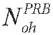
- In this implementation,

- Therefore, in the embodiment of the present disclosure, when calculating the transmission block size, the number of RE resources used for actual repeated transmission of the data channel is determined according to the slot configuration of the frame structure and the second slot repetition factor, capable of ensuring reasonable resource allocation and encoding parameters such as coding rate.
- Further, in some embodiments, the target number, NRE , of REs may be determined according to Equation (7):

where N' represents a second reference RE number threshold, nPRB represents a number of RBs allocated by a network device, and
- Optionally, in some embodiments, the second reference RE number threshold may be 156, or 156*X.
- That is, the target number, NRE , of REs can be determined according to the following Equation (8) or (9).


- Further, the terminal device may substitute Equation (7) into Equation (5) to obtain the intermediate number, N info , of information bits.
- Based on the above embodiments, the intermediate number, N info , of information bits can be determined.
- Further, in some embodiments, the terminal device may perform quantization and rounding on the intermediate number of information bits to determine the transport block size corresponding to the data channel.
- For example, a transport block size in a list of transport block sizes that is not smaller than the intermediate number of information bits and has a smallest difference with the intermediate number of information bits may be determined as the transport block size corresponding to the data channel.
- As an example, a list of TBSs is shown in Table 1. If the intermediate number of information bits determined according to the above embodiment is 101.9, the table can be searched for a TBS that is not smaller than 101.9 and is closest to 101.9, i.e., 104, as the TBS of the data channel.
Table 1 Index TBS Index TBS Index TBS Index TBS 1 24 31 336 61 1288 91 3624 2 32 32 352 62 1320 92 3752 3 40 33 368 63 1352 93 3824 4 48 34 384 64 1416 5 56 35 408 65 1480 6 64 36 432 66 1544 7 72 37 456 67 1608 8 80 38 480 68 1672 9 88 39 504 69 1736 10 96 40 528 70 1800 11 104 41 552 71 1864 12 112 42 576 72 1928 13 120 43 608 73 2024 14 128 44 640 74 2088 15 136 45 672 75 2152 16 144 46 704 76 2216 17 152 47 736 77 2280 18 160 48 768 78 2408 19 168 49 808 79 2472 20 176 50 848 80 2536 21 184 51 888 81 2600 22 192 52 928 82 2664 23 208 53 984 83 2728 24 224 54 1032 84 2792 25 240 55 1064 85 2856 26 256 56 1128 86 2976 27 272 57 1160 87 3104 28 288 58 1192 88 3240 29 304 59 1224 89 3368 30 320 60 1256 90 3496 - Optionally, in some embodiments of the present disclosure, S320 may further include:
obtaining the encoded information bits by performing channel coding according to the transport block size corresponding to the data channel and a number of REs in a plurality of repeated data resources scheduled by a network device. - Optionally, the number of REs in the plurality of repeated data resources may be indicated in DCI from a network device.
- In some embodiments, the number of bits after channel coding and rate matching corresponds to the number of REs.
- In an embodiment of the present disclosure, the operation of mapping the encoded information bits onto the plurality of slots may include:
mapping one redundant version of the encoded information bits successively onto the plurality of slots. - That is, in the embodiment of the present disclosure, only one redundant version can be mapped when encoding and mapping is performed, and the one redundant version can be mapped successively onto the plurality of slots. That is, the information bits mapped onto the plurality of slots may constitute one redundant version.
- Optionally, the plurality of slots may be slots for actually transmitting the data channel.
- For example, one redundancy version may be mapped onto REs of data resources scheduled in the slots for actual repeated transmission.
- The method embodiments of the present disclosure have been described in detail above with reference to
FIG. 3 , and the apparatus embodiments of the present disclosure will be described in detail below with reference toFIG. 4 to FIG. 7 . It can be appreciated that the apparatus embodiments and the method embodiments correspond to each other, and for similar descriptions, reference can be made to the method embodiments. -
FIG. 4 shows a schematic block diagram of adevice 400 for repeatedly transmitting data channel according to an embodiment of the present disclosure. As shown inFIG. 4 , thedevice 400 includes:
aprocessing unit 410 configured to - determine a transport block size corresponding to the data channel according to a first slot repetition factor and/or a number of time-domain symbols in slots for repeated transmission of the data channel;
- obtain encoded information bits by encoding the data channel according to the transport block size corresponding to the data channel; and
- map the encoded information bits onto a plurality of slots.
- Optionally, in some embodiments, the
processing unit 410 may be further configured to:
determine the transport block size corresponding to the data channel according to the first slot repetition factor and a scheduling parameter. - Optionally, in some embodiments, the scheduling parameter may include at least one of:
a target number of Resource Elements (REs), a coding rate, a modulation order, or a number of transmission layers. - Optionally, in some embodiments, the
processing unit 410 may be further configured to: - determine an intermediate number of information bits according to the first slot repetition factor and the scheduling parameter; and
- determine the transport block size corresponding to the data channel according to the intermediate number of information bits.
- Optionally, in some embodiments, the
processing unit 410 may be further configured to:
determine the intermediate number, N info , of information bits according to:

where NRE represents the target number of REs, R represents the coding rate, Qm represents the modulation order, υ represents the number of transmission layers, and X represents the first slot repetition factor. - Optionally, in some embodiments, the
processing unit 410 may be further configured to: - determine the target number of REs according to the first slot repetition factor; and
- determine the intermediate number of information bits according to the target number of REs and the scheduling parameter.
- Optionally, in some embodiments, the
processing unit 410 may be further configured to:
determine the target number of REs according to the first slot repetition factor and a reference number of available REs in one slot. - Optionally, in some embodiments, the
processing unit 410 may be further configured to:
determine the target number, NRE , of REs according to:

where X represents the first slot repetition factor, N represents a first reference RE number threshold, nPRB represents a number of Resource Blocks (RBs) allocated by a network device, and
- Optionally, the first reference RE number threshold may be 156.
- Optionally, in some embodiments, the
processing unit 410 may be further configured to:
determine the reference number,

where


- Optionally, in some embodiments, the
processing unit 410 may be further configured to: - determine a reference number of available REs in the slots for repeated transmission of the data channel according to the first slot repetition factor and the number of time-domain symbols in the slots for repeated transmission of the data channel; and
- determine the target number of REs according to the reference number of available REs in the slots for repeated transmission of the data channel.
- Optionally, in some embodiments, the
processing unit 410 may be further configured to:
determine the reference number,

where X represents the first slot repetition factor,

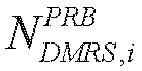

- Optionally, in some embodiments, the
processing unit 410 may be further configured to:
determine the target number, NRE , of REs according to:

where N ' represents a second reference RE number threshold, nPRB represents a number of RBs allocated by a network device, and
- Optionally, in some embodiments, the second reference RE number threshold may be 156∗X, or 156, where X represents the first slot repetition factor.
- Optionally, in some embodiments, the
processing unit 410 may be further configured to: perform quantization and rounding on the intermediate number of information bits to determine the transport block size corresponding to the data channel. - Optionally, in some embodiments, the
processing unit 410 may be further configured to:
determine a transport block size in a list of transport block sizes that is greater than or equal to the intermediate number of information bits and has a smallest difference with the intermediate number of information bits as the transport block size corresponding to the data channel. - Optionally, in some embodiments, the first slot repetition factor may be determined according to a second slot repetition factor configured by a network device.
- Optionally, in some embodiments, the first slot repetition factor may be the second slot repetition factor multiplied by a first coefficient, the first coefficient being smaller than or equal to 1.
- Optionally, in some embodiments, the first slot repetition factor may be configured by a network device.
- Optionally, in some embodiments, the first slot repetition factor may be configured via at least one of: Radio Resource Control (RRC) signaling or Downlink Control Information (DCI).
- Optionally, in some embodiments, the first slot repetition factor is determined according to the number of slots for actual repeated transmission of the data channel.
- Optionally, in some embodiments, the
processing unit 410 may be further configured to:
obtain the encoded information bits by performing channel coding according to the transport block size corresponding to the data channel and a number of REs in a plurality of repeated data resources scheduled by a network device. - Optionally, in some embodiments, the
processing unit 410 may be further configured to:
map one redundant version of the encoded information bits successively onto the plurality of slots. - Optionally, in some embodiments, the first slot repetition factor may be smaller than or equal to a second slot repetition factor configured by a network device, the second slot repetition factor indicating a number of slots for repeated transmission of the data channel.
- Optionally, in some embodiments, the
device 400 may be a terminal device or a network device. - Optionally, in some embodiments, the above communication unit may be a communication interface or a transceiver, or an input/output interface of a communication chip or a system-on-chip. The
above processing unit 410 may be one or more processors. - It can be appreciated that the
device 400 according to the embodiment of the present disclosure may correspond to the terminal device or network device in the method embodiment of the present disclosure, and the above and other operations and/or functions of the respective units in thedevice 400 are provided for the purpose of implementing the process flow corresponding to the terminal device or network device in themethod 300 shown inFIG. 3 , and details thereof will be not omitted here for brevity. -
FIG. 5 is a schematic diagram showing a structure of acommunication device 600 according to an embodiment of the present disclosure. Thecommunication device 600 shown inFIG. 5 includes aprocessor 610, and theprocessor 610 can invoke and execute a computer program from a memory to implement the method in the embodiment of the present disclosure. - Optionally, as shown in
FIG. 5 , thecommunication device 600 may further include amemory 620. Theprocessor 610 can invoke and execute a computer program from thememory 620 to implement the method in the embodiment of the present disclosure. Thememory 620 may be a separate device independent from theprocessor 610, or may be integrated in theprocessor 610. - Optionally, as shown in
FIG. 5 , thecommunication device 600 may further include atransceiver 630, and theprocessor 610 may control thetransceiver 630 to communicate with other devices, and in particular, transmit information or data to other devices, or receive information or data transmitted by other devices. - Here, the
transceiver 630 may include a transmitter and a receiver. Thetransceiver 630 may further include one or more antennas. - Optionally, the
communication device 600 may specifically be the network device according to the embodiment of the present disclosure, and thecommunication device 600 may implement the corresponding processes implemented by the network device in any of the methods according to the embodiments of the present disclosure. For the sake of brevity, details thereof will be omitted here. - Optionally, the
communication device 600 may specifically be the mobile terminal/terminal device according to the embodiment of the present disclosure, and thecommunication device 600 may implement the corresponding processes implemented by the mobile terminal/terminal device in any of the methods according to the embodiments of the present disclosure. For the sake of brevity, details thereof will be omitted here. -
FIG. 6 is a schematic diagram showing a structure of a chip according to an embodiment of the present disclosure. Thechip 700 shown inFIG. 6 includes aprocessor 710, and theprocessor 710 can invoke and execute a computer program from a memory to implement the method in the embodiment of the present disclosure. - Optionally, as shown in
FIG. 6 , thechip 700 may further include amemory 720. Theprocessor 710 can invoke and execute a computer program from thememory 720 to implement the method in the embodiment of the present disclosure. Thememory 720 may be a separate device independent from theprocessor 710, or may be integrated in theprocessor 710. - Optionally, the
chip 700 may further include aninput interface 730. Theprocessor 710 can control theinput interface 730 to communicate with other devices or chips, and in particular, obtain information or data transmitted by other devices or chips. - Optionally, the
chip 700 may further include anoutput interface 740. Theprocessor 710 can control theoutput interface 740 to communicate with other devices or chips, and in particular, output information or data to other devices or chips. - Optionally, the chip can be applied to the network device in the embodiment of the present disclosure, and the chip can implement the corresponding processes implemented by the network device in the various methods of the embodiments of the present disclosure. For the sake of brevity, details thereof will be omitted here.
- Optionally, the chip can be applied to the mobile terminal/terminal device in the embodiment of the present disclosure, and the chip can implement the corresponding processes implemented by the mobile terminal/terminal device in the various methods of the embodiments of the present disclosure. For the sake of brevity, details thereof will be omitted here.
- Optionally, the chip in the embodiment of the present disclosure may be a system-level chip, a system-chip, a chip system, or a system-on-chip.
-
FIG. 7 is a schematic block diagram showing acommunication system 900 according to an embodiment of the present disclosure. As shown inFIG. 7 , thecommunication system 900 includes aterminal device 910 and anetwork device 920. Here, theterminal device 910 can be configured to implement the corresponding functions implemented by the terminal device in the above method, and thenetwork device 920 can be configured to implement the corresponding functions implemented by the network device in the above method. For the sake of brevity, details thereof will be omitted here. - It is to be noted that the processor in the embodiment of the present disclosure may be an integrated circuit chip with signal processing capability. In an implementation, the steps of the above method embodiments can be implemented by hardware integrated logic circuits in a processor or instructions in the form of software. The processor can be a general purpose processor, a Digital Signal Processor (DSP), an Application Specific Integrated Circuit (ASIC), a Field Programmable Gate Array (FPGA) or another programmable logic device, a discrete gate or transistor logic device, or a discrete hardware component. The methods, steps, and logical block diagrams disclosed in the embodiments of the present disclosure can be implemented or performed. The general purpose processor may be a microprocessor or any conventional processor. The steps of the methods disclosed in the embodiments of the present disclosure may be directly embodied as being performed and completed by a hardware decoding processor, or by a combination of hardware and software modules in the decoding processor. The software modules can be located in a known storage medium in the related art, such as random access memory, flash memory, read-only memory, programmable read-only memory, electrically erasable programmable memory, or register. The storage medium can be located in the memory, and the processor can read information from the memory and perform the steps of the above methods in combination with its hardware.
- It can be appreciated that the memory in the embodiments of the present disclosure may be a volatile memory or a non-volatile memory, or may include both volatile and non-volatile memories. Here, the non-volatile memory may be a Read-Only Memory (ROM), a Programmable ROM (PROM), an Erasable PROM (EPROM), an Electrically EPROM (EEPROM), or a flash memory. The volatile memory may be a Random Access Memory (RAM), which is used as an external cache. As illustrative, rather than limiting, examples, many forms of RAMs are available, including Static RAM (SRAM), Dynamic RAM (DRAM), Synchronous DRAM (SDRAM), Double Data Rate SDRAM (DDR SDRAM), Enhanced SDRAM (ESDRAM), Synchlink DRAM (SLDRAM) ), and Direct Rambus RAM (DR RAM). It is to be noted that the memory used for the system and method described in the present disclosure is intended to include, but not limited to, these and any other suitable types of memories.
- It can be appreciated that the above memories are exemplary only, rather than limiting the present disclosure. For example, the memory in the embodiment of the present disclosure may also be a Static RAM (SRAM), a Dynamic RAM (DRAM), a Synchronous DRAM (SDRAM), a Double Data Rate SDRAM (DDR SDRAM), an Enhanced SDRAM (ESDRAM), a Synch Link DRAM (SLDRAM), or a Direct Rambus RAM (DR RAM). That is, the memory in the embodiments of the present disclosure is intended to include, but not limited to, these and any other suitable types of memories.
- An embodiment of the present disclosure also provides a computer readable storage medium for storing a computer program.
- Optionally, the computer readable storage medium can be applied to the network device in the embodiment of the present disclosure, and the computer program can cause a computer to perform corresponding procedures implemented by the network device in the method according to any of the embodiments of the present disclosure. Details thereof will be omitted here for simplicity.
- Optionally, the computer readable storage medium can be applied to the mobile terminal/terminal device in the embodiment of the present disclosure, and the computer program can cause a computer to perform corresponding procedures implemented by the mobile terminal/terminal device in the method according to any of the embodiments of the present disclosure. Details thereof will be omitted here for simplicity.
- An embodiment of the present disclosure also provides a computer program product including computer program instructions.
- Optionally, the computer program product can be applied to the network device in the embodiment of the present disclosure, and the computer program instructions can cause a computer to perform corresponding procedures implemented by the network device in the method according to any of the embodiments of the present disclosure. Details thereof will be omitted here for simplicity.
- Optionally, the computer program product can be applied to the mobile terminal/terminal device in the embodiment of the present disclosure, and the computer program instructions can cause a computer to perform corresponding procedures implemented by the mobile terminal/terminal device in the method according to any of the embodiments of the present disclosure. Details thereof will be omitted here for simplicity.
- An embodiment of the present disclosure also provides a computer program.
- Optionally, the computer program can be applied to the network device in the embodiment of the present disclosure. The computer program, when executed on a computer, can cause the computer to perform corresponding procedures implemented by the network device in the method according to any of the embodiments of the present disclosure. Details thereof will be omitted here for simplicity.
- Optionally, the computer program can be applied to the mobile terminal/terminal device in the embodiment of the present disclosure. The computer program, when executed on a computer, can cause the computer to perform corresponding procedures implemented by the mobile terminal/terminal device in the method according to any of the embodiments of the present disclosure. Details thereof will be omitted here for simplicity.
- It can be appreciated by those skilled in the art that units and algorithm steps in the examples described in connection with the embodiments disclosed herein can be implemented in electronic hardware or any combination of computer software and electronic hardware. Whether these functions are executed by hardware or software depends on specific applications and design constraint conditions of the technical solutions. Those skilled in the art may use different methods for each specific application to implement the described functions, and such implementation is to be encompassed by the scope of this disclosure.
- Those skilled in the art can clearly understand that, for the convenience and conciseness of the description, for the specific operation processes of the systems, devices, and units described above, reference can be made to the corresponding processes in the foregoing method embodiments, and details thereof will be omitted here.
- In the embodiments of the present disclosure, it can be appreciated that the disclosed systems, devices, and methods may be implemented in other ways. For example, the device embodiments described above are illustrative only. For example, the divisions of the units are only divisions based on logical functions, and there may be other divisions in actual implementations. For example, more than one unit or component may be combined or integrated into another system, or some features can be ignored or omitted. In addition, the mutual coupling or direct coupling or communicative connection as shown or discussed may be indirect coupling or communicative connection between devices or units via some interfaces which may be electrical, mechanical, or in any other forms.
- The units described as separate components may or may not be physically separated, and the components shown as units may or may not be physical units, that is, they may be co-located or distributed across a number of network elements. Some or all of the units may be selected according to actual needs to achieve the objects of the solutions of the embodiments.
- In addition, the functional units in the embodiments of the present disclosure may be integrated into one processing unit, or alternatively be separate physical modules, or two or more units may be integrated into one unit.
- When the function is implemented in the form of a software functional unit and sold or used as a standalone product, it can be stored in a computer readable storage medium. Based on this understanding, all or part of the technical solutions according to the embodiments of the present disclosure, or the part thereof that contributes to the prior art, can be embodied in the form of a software product. The computer software product may be stored in a storage medium and contain instructions to enable a computer device, such as a personal computer, a server, or a network device, etc., to perform all or part of the steps of the method described in each of the embodiments of the present disclosure. The storage medium may include a Universal Serial Bus flash drive, a mobile hard disk, a Read-Only Memory (ROM), a Random Access Memory (RAM), a magnetic disk, an optical disc, or any other medium capable of storing program codes.
- While the specific embodiments of the present disclosure have been described above, the scope of the present disclosure is not limited to these embodiments. Various variants and alternatives can be made by those skilled in the art without departing from the scope of the present disclosure. These variants and alternatives are to be encompassed by the scope of present disclosure as defined by the claims as attached.
Claims (52)
- A method for repeatedly transmitting data channel, comprising:determining a transport block size corresponding to the data channel according to a first slot repetition factor and/or a number of time-domain symbols in slots for repeated transmission of the data channel;obtaining encoded information bits by encoding the data channel according to the transport block size corresponding to the data channel; andmapping the encoded information bits onto a plurality of slots.
- The method according to claim 1, wherein said determining the transport block size corresponding to the data channel according to the first slot repetition factor and/or the number of time-domain symbols in the slots for repeated transmission of the data channel comprises:
determining the transport block size corresponding to the data channel according to the first slot repetition factor and a scheduling parameter. - The method according to claim 2, wherein the scheduling parameter comprises at least one of:
a target number of Resource Elements (REs), a coding rate, a modulation order, or a number of transmission layers. - The method according to claim 2 or 3, wherein said determining the transport block size corresponding to the data channel according to the first slot repetition factor and the scheduling parameter comprises:determining an intermediate number of information bits according to the first slot repetition factor and the scheduling parameter; anddetermining the transport block size corresponding to the data channel according to the intermediate number of information bits.
- The method according to claim 4, wherein said determining the intermediate number of information bits according to the first slot repetition factor and the scheduling parameter comprises:
determining the intermediate number, N info , of information bits according to:
- The method according to claim 4, wherein said determining the intermediate number of information bits according to the first slot repetition factor and the scheduling parameter comprises:determining a target number of REs according to the first slot repetition factor; anddetermining the intermediate number of information bits according to the target number of REs and the scheduling parameter.
- The method according to claim 6, wherein said determining the target number of REs according to the first slot repetition factor comprises:
determining the target number of REs according to the first slot repetition factor and a reference number of available REs in one slot. - The method according to claim 7, wherein said determining the target number of REs according to the first slot repetition factor and the reference number of available REs in one slot comprises:
determining the target number, NRE , of REs according to:

- The method according to claim 7 or 8, further comprising:
determining the reference number,


- The method according to claim 6, wherein said determining the target number of REs according to the first slot repetition factor comprises:determining a reference number of available REs in the slots for repeated transmission of the data channel according to the first slot repetition factor and the number of time-domain symbols in the slots for repeated transmission of the data channel; anddetermining the target number of REs according to the reference number of available REs in the slots for repeated transmission of the data channel.
- The method according to claim 10, wherein said determining the reference number of available REs in the slots for repeated transmission of the data channel according to the first slot repetition factor and the number of time-domain symbols in the slots for repeated transmission of the data channel comprises:
determining the reference number,


- The method according to claim 10 or 11, wherein said determining the target number of REs according to the reference number of available REs in the slots for repeated transmission of the data channel comprises:
determining the target number, NRE , of REs according to:

- The method according to claim 10 or 11, wherein the second reference RE number threshold is 156*X, or 156, where X represents the first slot repetition factor.
- The method according to any one of claims 4 to 13, wherein said determining the transport block size corresponding to the data channel according to the intermediate number of information bits comprises:
performing quantization and rounding on the intermediate number of information bits to determine the transport block size corresponding to the data channel. - The method according to claim 14, wherein said performing quantization and rounding on the intermediate number of information bits to determine the transport block size corresponding to the data channel comprises:
determining a transport block size in a list of transport block sizes that is greater than or equal to the intermediate number of information bits and has a smallest difference with the intermediate number of information bits as the transport block size corresponding to the data channel. - The method according to any one of claims 1 to 15, wherein the first slot repetition factor is determined according to a second slot repetition factor configured by a network device.
- The method according to claim 16, wherein the first slot repetition factor is the second slot repetition factor multiplied by a first coefficient, the first coefficient being smaller than or equal to 1.
- The method according to any one of claims 1 to 15, wherein the first slot repetition factor is configured by a network device.
- The method according to claim 18, wherein the first slot repetition factor is configured via at least one of: Radio Resource Control (RRC) signaling or Downlink Control Information (DCI).
- The method according to any one of claims 1 to 15, wherein the first slot repetition factor is determined according to a number of slots for actual repeated transmission of the data channel.
- The method according to any one of claims 1 to 20, wherein said obtaining the encoded information bits by encoding the data channel according to the transport block size corresponding to the data channel comprises:
obtaining the encoded information bits by performing channel coding according to the transport block size corresponding to the data channel and a number of REs in a plurality of repeated data resources scheduled by a network device. - The method according to any one of claims 1 to 21, wherein said mapping the encoded information bits onto the plurality of slots comprises:
mapping one redundant version of the encoded information bits successively onto the plurality of slots. - The method according to any one of claims 1 to 22, wherein the first slot repetition factor is smaller than or equal to a second slot repetition factor configured by a network device, the second slot repetition factor indicating a number of slots for repeated transmission of the data channel.
- A device for repeatedly transmitting data channel, comprising:
a processing unit configured to:determine a transport block size corresponding to the data channel according to a first slot repetition factor and/or a number of time-domain symbols in slots for repeated transmission of the data channel;obtain encoded information bits by encoding the data channel according to the transport block size corresponding to the data channel; andmap the encoded information bits onto a plurality of slots. - The device according to claim 24, wherein the processing unit is further configured to:
determine the transport block size corresponding to the data channel according to the first slot repetition factor and a scheduling parameter. - The device according to claim 25, wherein the scheduling parameter comprises at least one of:
a target number of Resource Elements (REs), a coding rate, a modulation order, or a number of transmission layers. - The device according to claim 25 or 26, wherein the processing unit is further configured to:determine an intermediate number of information bits according to the first slot repetition factor and the scheduling parameter; anddetermine the transport block size corresponding to the data channel according to the intermediate number of information bits.
- The device according to claim 27, wherein the processing unit is further configured to:
determine the intermediate number, N info , of information bits according to:
- The device according to claim 27, wherein the processing unit is further configured to:determine a target number of REs according to the first slot repetition factor; anddetermine the intermediate number of information bits according to the target number of REs and the scheduling parameter.
- The device according to claim 29, wherein the processing unit is further configured to:
determine the target number of REs according to the first slot repetition factor and a reference number of available REs in one slot. - The device according to claim 30, wherein the processing unit is further configured to:
determine the target number, NRE , of REs according to:

- The device according to claim 30 or 31, wherein the processing unit is further configured to:
determine the reference number,


- The device according to claim 29, wherein the processing unit is further configured to:determine a reference number of available REs in the slots for repeated transmission of the data channel according to the first slot repetition factor and the number of time-domain symbols in the slots for repeated transmission of the data channel; anddetermine the target number of REs according to the reference number of available REs in the slots for repeated transmission of the data channel.
- The device according to claim 33, wherein the processing unit is further configured to:
determine the reference number,


- The device according to claim 33 or 34, wherein the processing unit is further configured to:
determine the target number, NRE , of REs according to:

- The device according to claim 33 or 34, wherein the second reference RE number threshold is 156*X, or 156, where X represents the first slot repetition factor.
- The device according to any one of claims 27 to 36, wherein the processing unit is further configured to:
perform quantization and rounding on the intermediate number of information bits to determine the transport block size corresponding to the data channel. - The device according to claim 37, wherein the processing unit is further configured to:
determine a transport block size in a list of transport block sizes that is greater than or equal to the intermediate number of information bits and has a smallest difference with the intermediate number of information bits as the transport block size corresponding to the data channel. - The device according to any one of claims 24 to 38, wherein the first slot repetition factor is determined according to a second slot repetition factor configured by a network device.
- The device according to claim 39, wherein the first slot repetition factor is the second slot repetition factor multiplied by a first coefficient, the first coefficient being smaller than or equal to 1.
- The device according to any one of claims 24 to 38, wherein the first slot repetition factor is configured by a network device.
- The device according to claim 41, wherein the first slot repetition factor is configured via at least one of: Radio Resource Control (RRC) signaling or Downlink Control Information (DCI).
- The device according to any one of claims 24 to 38, wherein the first slot repetition factor is determined according to a number of slots for actual repeated transmission of the data channel.
- The device according to any one of claims 24 to 43, wherein the processing unit is further configured to:
obtain the encoded information bits by performing channel coding according to the transport block size corresponding to the data channel and a number of REs in a plurality of repeated data resources scheduled by a network device. - The device according to any one of claims 24 to 44, wherein the processing unit is further configured to:
map one redundant version of the encoded information bits successively onto the plurality of slots. - The device according to any one of claims 24 to 45, wherein the first slot repetition factor is smaller than or equal to a second slot repetition factor configured by a network device, the second slot repetition factor indicating a number of slots for repeated transmission of the data channel.
- The device according to any one of claims 24 to 46, wherein the device is a terminal device or a network device.
- A communication device, comprising a processor and a memory, wherein the memory has a computer program stored thereon, and the processor is configured to invoke and execute the computer program stored in the memory to perform the method according to any of claims 1 to 23.
- A chip, comprising a processor configured to invoke and execute a computer program from a memory, to cause a device provided with the chip to perform the method according to any of claims 1 to 23.
- A computer-readable storage medium, storing a computer program that causes a computer to perform the method according to any of claims 1 to 23.
- A computer program product, comprising computer program instructions that cause a computer to perform the method according to any of claims 1 to 23.
- A computer program, causing a computer to perform the method according to any of claims 1 to 23.
Applications Claiming Priority (1)
| Application Number | Priority Date | Filing Date | Title |
|---|---|---|---|
| PCT/CN2020/141059 WO2022141106A1 (en) | 2020-12-29 | 2020-12-29 | Method and device for repeatedly transmitting data channel |
Publications (2)
| Publication Number | Publication Date |
|---|---|
| EP4270831A1 true EP4270831A1 (en) | 2023-11-01 |
| EP4270831A4 EP4270831A4 (en) | 2024-02-21 |
Family
ID=82258764
Family Applications (1)
| Application Number | Title | Priority Date | Filing Date |
|---|---|---|---|
| EP20967454.8A Pending EP4270831A4 (en) | 2020-12-29 | 2020-12-29 | METHOD AND DEVICE FOR REPEATED TRANSMISSION OF A DATA CHANNEL |
Country Status (4)
| Country | Link |
|---|---|
| US (1) | US20230362915A1 (en) |
| EP (1) | EP4270831A4 (en) |
| CN (1) | CN116458236B (en) |
| WO (1) | WO2022141106A1 (en) |
Families Citing this family (1)
| Publication number | Priority date | Publication date | Assignee | Title |
|---|---|---|---|---|
| CN119605092A (en) * | 2022-10-27 | 2025-03-11 | Oppo广东移动通信有限公司 | Wireless communication method, terminal device and network device |
Family Cites Families (8)
| Publication number | Priority date | Publication date | Assignee | Title |
|---|---|---|---|---|
| US10992408B2 (en) * | 2018-05-11 | 2021-04-27 | Qualcomm Incorporated | Transport block size scaling factor indication for ultra-reliable low-latency communication |
| CN110830183B (en) * | 2018-08-09 | 2023-09-19 | 北京三星通信技术研究有限公司 | Uplink transmission method, user equipment, base station and computer-readable medium |
| US11411690B2 (en) * | 2018-11-21 | 2022-08-09 | Electronics And Telecommunications Research Institute | Method for transmitting and receiving data channel based on a plurality of physical uplink shared channels in communication system and apparatus for the same |
| EP3925366A1 (en) * | 2019-02-15 | 2021-12-22 | Telefonaktiebolaget LM Ericsson (publ) | Transmit format for multi-segment pusch |
| EP3925120A4 (en) * | 2019-02-15 | 2022-07-27 | ZTE Corporation | Resource indication scheme for repeated transmissions |
| CN110278614B (en) * | 2019-06-24 | 2020-12-18 | 西安理工大学 | A data channel transmission method and device |
| US12199763B2 (en) * | 2020-08-06 | 2025-01-14 | Samsung Electronics Co., Ltd. | Transport block mapping across slots |
| JP2024020669A (en) * | 2020-12-24 | 2024-02-15 | シャープ株式会社 | Terminal device, base station device, and communication method |
-
2020
- 2020-12-29 CN CN202080107050.3A patent/CN116458236B/en active Active
- 2020-12-29 EP EP20967454.8A patent/EP4270831A4/en active Pending
- 2020-12-29 WO PCT/CN2020/141059 patent/WO2022141106A1/en not_active Ceased
-
2023
- 2023-06-28 US US18/215,552 patent/US20230362915A1/en active Pending
Also Published As
| Publication number | Publication date |
|---|---|
| CN116458236B (en) | 2025-04-08 |
| WO2022141106A1 (en) | 2022-07-07 |
| US20230362915A1 (en) | 2023-11-09 |
| CN116458236A (en) | 2023-07-18 |
| EP4270831A4 (en) | 2024-02-21 |
Similar Documents
| Publication | Publication Date | Title |
|---|---|---|
| US12490287B2 (en) | Wireless communication method and terminal device | |
| US12610383B2 (en) | Physical sidelink feedback channel (PSFCH) transmission method and terminal device | |
| US20240023076A1 (en) | Method for channel estimation, terminal device, and network device | |
| US20230362915A1 (en) | Method and device for repeatedly transmitting data channel | |
| EP3787327A1 (en) | Data transmission method, and communication device | |
| EP4290955B1 (en) | Wireless communication method, terminal device, and network device | |
| US20240323904A1 (en) | Wireless communication method and terminal device | |
| EP4132156B1 (en) | Data transmission method, terminal device, and network device | |
| US20240323975A1 (en) | Wireless communication method, terminal device, and network device | |
| US20240080860A1 (en) | Wireless communication methods, terminal devices, and network device | |
| CN110035548A (en) | The method and communication equipment of communication | |
| US20230353292A1 (en) | Wireless communication method and device | |
| US12598605B2 (en) | Wireless communication method and device | |
| US12438667B2 (en) | Wireless communication method, terminal device, and network device | |
| EP4319386A1 (en) | Wireless communication method, terminal device, and network device | |
| CN119111110A (en) | Resource indication method, device, equipment, storage medium and program product | |
| CN118044292A (en) | Resource indication method, terminal device and network device | |
| EP4657945A1 (en) | Resource indication method, terminal device, and network device | |
| US20230224908A1 (en) | Method for repeatedly transmitting control channel, terminal device, and network device | |
| EP4642115A1 (en) | Wireless communication method, terminal device, and network device | |
| US20250038815A1 (en) | Wireless communication methods, terminal devices and network devices | |
| US20240334444A1 (en) | Method for wireless communication, terminal device, and network device | |
| US20240340908A1 (en) | Wireless communication method, terminal device, and network device | |
| US20250097856A1 (en) | Wireless communication method, terminal device, and network device | |
| US20250112803A1 (en) | Method for generating sequence, and communication device |
Legal Events
| Date | Code | Title | Description |
|---|---|---|---|
| STAA | Information on the status of an ep patent application or granted ep patent |
Free format text: STATUS: THE INTERNATIONAL PUBLICATION HAS BEEN MADE |
|
| PUAI | Public reference made under article 153(3) epc to a published international application that has entered the european phase |
Free format text: ORIGINAL CODE: 0009012 |
|
| STAA | Information on the status of an ep patent application or granted ep patent |
Free format text: STATUS: REQUEST FOR EXAMINATION WAS MADE |
|
| 17P | Request for examination filed |
Effective date: 20230726 |
|
| AK | Designated contracting states |
Kind code of ref document: A1 Designated state(s): AL AT BE BG CH CY CZ DE DK EE ES FI FR GB GR HR HU IE IS IT LI LT LU LV MC MK MT NL NO PL PT RO RS SE SI SK SM TR |
|
| REG | Reference to a national code |
Ref country code: DE Ref legal event code: R079 Free format text: PREVIOUS MAIN CLASS: H04L0001180000 Ipc: H04L0001080000 |
|
| A4 | Supplementary search report drawn up and despatched |
Effective date: 20240119 |
|
| RIC1 | Information provided on ipc code assigned before grant |
Ipc: H04L 1/00 20060101ALN20240115BHEP Ipc: H04L 1/1829 20230101ALI20240115BHEP Ipc: H04L 1/1812 20230101ALI20240115BHEP Ipc: H04L 1/1867 20230101ALI20240115BHEP Ipc: H04L 1/08 20060101AFI20240115BHEP |
|
| DAV | Request for validation of the european patent (deleted) | ||
| DAX | Request for extension of the european patent (deleted) | ||
| STAA | Information on the status of an ep patent application or granted ep patent |
Free format text: STATUS: EXAMINATION IS IN PROGRESS |
|
| 17Q | First examination report despatched |
Effective date: 20241023 |