EP4270825A1 - Method and device for time validation in a vehicle - Google Patents
Method and device for time validation in a vehicle Download PDFInfo
- Publication number
- EP4270825A1 EP4270825A1 EP22169651.1A EP22169651A EP4270825A1 EP 4270825 A1 EP4270825 A1 EP 4270825A1 EP 22169651 A EP22169651 A EP 22169651A EP 4270825 A1 EP4270825 A1 EP 4270825A1
- Authority
- EP
- European Patent Office
- Prior art keywords
- time
- position information
- vehicle
- received
- timestamp
- Prior art date
- Legal status (The legal status is an assumption and is not a legal conclusion. Google has not performed a legal analysis and makes no representation as to the accuracy of the status listed.)
- Granted
Links
Images
Classifications
-
- H—ELECTRICITY
- H04—ELECTRIC COMMUNICATION TECHNIQUE
- H04J—MULTIPLEX COMMUNICATION
- H04J3/00—Time-division multiplex systems
- H04J3/02—Details
- H04J3/14—Monitoring arrangements
-
- G—PHYSICS
- G01—MEASURING; TESTING
- G01S—RADIO DIRECTION-FINDING; RADIO NAVIGATION; DETERMINING DISTANCE OR VELOCITY BY USE OF RADIO WAVES; LOCATING OR PRESENCE-DETECTING BY USE OF THE REFLECTION OR RERADIATION OF RADIO WAVES; ANALOGOUS ARRANGEMENTS USING OTHER WAVES
- G01S19/00—Satellite radio beacon positioning systems; Determining position, velocity or attitude using signals transmitted by such systems
- G01S19/01—Satellite radio beacon positioning systems transmitting time-stamped messages, e.g. GPS [Global Positioning System], GLONASS [Global Orbiting Navigation Satellite System] or GALILEO
- G01S19/13—Receivers
- G01S19/24—Acquisition or tracking or demodulation of signals transmitted by the system
- G01S19/25—Acquisition or tracking or demodulation of signals transmitted by the system involving aiding data received from a cooperating element, e.g. assisted GPS
- G01S19/256—Acquisition or tracking or demodulation of signals transmitted by the system involving aiding data received from a cooperating element, e.g. assisted GPS relating to timing, e.g. time of week, code phase, timing offset
-
- B—PERFORMING OPERATIONS; TRANSPORTING
- B60—VEHICLES IN GENERAL
- B60W—CONJOINT CONTROL OF VEHICLE SUB-UNITS OF DIFFERENT TYPE OR DIFFERENT FUNCTION; CONTROL SYSTEMS SPECIALLY ADAPTED FOR HYBRID VEHICLES; ROAD VEHICLE DRIVE CONTROL SYSTEMS FOR PURPOSES NOT RELATED TO THE CONTROL OF A PARTICULAR SUB-UNIT
- B60W60/00—Drive control systems specially adapted for autonomous road vehicles
- B60W60/001—Planning or execution of driving tasks
- B60W60/0015—Planning or execution of driving tasks specially adapted for safety
-
- H—ELECTRICITY
- H04—ELECTRIC COMMUNICATION TECHNIQUE
- H04J—MULTIPLEX COMMUNICATION
- H04J3/00—Time-division multiplex systems
- H04J3/02—Details
- H04J3/06—Synchronising arrangements
- H04J3/0635—Clock or time synchronisation in a network
- H04J3/0638—Clock or time synchronisation among nodes; Internode synchronisation
- H04J3/0658—Clock or time synchronisation among packet nodes
- H04J3/0661—Clock or time synchronisation among packet nodes using timestamps
-
- H—ELECTRICITY
- H04—ELECTRIC COMMUNICATION TECHNIQUE
- H04J—MULTIPLEX COMMUNICATION
- H04J3/00—Time-division multiplex systems
- H04J3/02—Details
- H04J3/06—Synchronising arrangements
- H04J3/0635—Clock or time synchronisation in a network
- H04J3/0638—Clock or time synchronisation among nodes; Internode synchronisation
- H04J3/0658—Clock or time synchronisation among packet nodes
- H04J3/0661—Clock or time synchronisation among packet nodes using timestamps
- H04J3/0664—Clock or time synchronisation among packet nodes using timestamps unidirectional timestamps
-
- H—ELECTRICITY
- H04—ELECTRIC COMMUNICATION TECHNIQUE
- H04L—TRANSMISSION OF DIGITAL INFORMATION, e.g. TELEGRAPHIC COMMUNICATION
- H04L67/00—Network arrangements or protocols for supporting network services or applications
- H04L67/01—Protocols
- H04L67/12—Protocols specially adapted for proprietary or special-purpose networking environments, e.g. medical networks, sensor networks, networks in vehicles or remote metering networks
Definitions
- the present disclosure is directed to a method for time validation in a vehicle, to a data processing system comprising means for carrying out the method, a computer program comprising instructions which, when the program is executed by a computer, cause the computer to carry out the method, and a computer-readable medium comprising instructions which, when executed by a computer, cause the computer to carry out the method.
- ECUs electronice control units
- ASIL Automotive Safety Integrity Level
- the Automotive Safety Integrity Level is a risk classification scheme defined by ISO 26262 - Functional Safety for Road Vehicles.
- the ASIL classification comprises four safety levels, starting from ASIL A with the lowest safety requirements to ASIL D having the highest safety requirements. Furthermore, hazards that are identified as QM do not dictate any safety requirements.
- Time synchronization for highly automated vehicles e.g. a car of a SAE Level 3 or Level 4 or higher (wherein the SAE J3016 standard describes classification and definition of terms for road-bound vehicles with automated driving systems), need to fulfill ASIL B or higher.
- time synchronization of for example an Ethernet bus is done according to IEEE 802.1AS for a TSN (time sensitive network) and IEEE 1588 with respect to the PTP (Precision Time Protocol).
- TSN time sensitive network
- PTP Precision Time Protocol
- a vehicle may comprise different environment sensors which are configured to provide sensor data with regards to the environment of the vehicle.
- a control unit within the vehicle may make use of and/or may fuse the sensor data from the different environment sensors to determine an environment model which indicates the position of objects within the environment of the vehicle.
- the vehicle may then be operated, e.g. within an autonomous driving mode, based on the environment model.
- the environment sensors may be located in one or more different communications networks or communications bus systems of the vehicle.
- Example communication bus systems are a Controller Area Network (CAN), notable a CAN-FD (Flexible Data-Rate), bus system, a FlexRay bus system, a Local Interconnect Network (LIN) bus system, a Media Oriented Systems Transport (MOST) bus system and/or an Ethernet bus system.
- CAN Controller Area Network
- CAN-FD Flexible Data-Rate
- FlexRay FlexRay
- LIN Local Interconnect Network
- MOST Media Oriented Systems Transport
- the different environment sensors typically each comprise a local time clock which is configured to provide a time stamp for the sensor data which is captured by the respective environment sensor.
- the time stamps of the sensor data which is provided by the different sensors are typically taken into account when fusing the sensor data to determine the environment model.
- Differences in the local times which are indicated by the local time clocks of the different environment sensors may lead to inaccuracies of the environment model and may impair autonomous driving.
- WO2021204342A1 discloses a method for performing time-synchronization between a master clock of a master unit and a plurality of slave clocks of a corresponding plurality of slave units within a communication bus system.
- the method comprises sending a forward time-synchronization message indicative of the master clock from the master unit to the plurality of slave units, in order to enable the plurality of slave units to time-synchronize their respective slave clocks with the master clock.
- the method further comprises receiving a reverse time-synchronization message indicative of the respective slave clock from each of the plurality of slave units at a first validator.
- the method comprises time-synchronizing a plurality of validator clocks of the first validator to the corresponding plurality of slave clocks using the reverse time-synchronization messages from the plurality of slave units, and validating the time-synchronization between the plurality of slave clocks at the first validator based on the plurality of validator clocks of the first validator.
- GNSS global navigation satellite system
- time stamping is also part of the above-described safety goal in order to be able to know the time and the location of the vehicle and use this data later on in the sensor fusion ECU and/or to detect a location of the vehicle on a map.
- ASIL-B receiver chips
- one object of the present disclosure is, inter alia, to provide a device and a method which are suitable for overcoming at least some of the above-mentioned disadvantages of the prior art, respectively.
- the object is solved by a method for time validation in a vehicle.
- the method may be a computer-implemented method.
- the method may also be called a method for timestamp validation provided to position information by a data processing unit installed in a vehicle.
- the method comprises receiving a first position information at a receiving unit of the vehicle, the received first position information comprises a first time information.
- the method comprises providing a first timestamp to the received first position information based on a vehicle time at the time of receiving the first position information.
- the method comprises receiving a second position information at a receiving unit of the vehicle, the received second position information comprises a second time information.
- the method comprises providing a second timestamp to the received second position information based on the vehicle time at the time of receiving the second position information.
- the method comprises determining if a difference between the first and the second time information and a difference between the first and the second timestamp are the same and/or if a deviation between the two differences is below a predefined threshold.
- the position information may be received from a satellite navigation or satnav system which is a system that uses satellites to provide autonomous geo-spatial positioning. It allows small electronic receivers to determine their location (longitude, latitude, and/or altitude/elevation) to high precision (e.g., within a few centimetres to metres) using time signals transmitted along a line of sight by radio from satellites.
- the system can be used for providing position, navigation or for tracking the position of something fitted with a receiver (satellite tracking).
- the signals also allow the electronic receiver to calculate the current local time to high precision, which allows time synchronization.
- PNT Positioning, Navigation and Timing
- Satnav systems operate independently of any telephonic or internet reception, though these technologies can enhance the usefulness of the positioning information generated.
- GNSS global navigation satellite system
- the position information may be provided by such a GNSS and may also be called GNSS (position) information.
- a global navigation satellite system, or GNSS is a system for determining position and navigation on earth and in the air by receiving signals from navigation satellites and pseudolites.
- GNSS is a collective term for the use of existing and future global satellite systems such as: NAVSTAR GPS (Global Positioning System) of the United States of America, GLONASS (Global Navigation Satellite System) of the Russian Federation, Galileo of the European Union, and Beidou of the People's Republic of China and various supplementary systems of Europe, the USA, Japan and India.
- the respective positioning information may allow the vehicle to determine its location, e.g. based on a respective time information included in the position information.
- a GPS receiver calculates its own four-dimensional position in spacetime based on data received from multiple GPS satellites. Each satellite carries an accurate record of its position and time, and transmits that data as position information to the receiver.
- the satellites carry very stable atomic clocks that are synchronized with one another and with ground clocks. Any drift from time maintained on the ground is corrected daily. In the same manner, the satellite locations are known with great precision.
- the GPS receivers have clocks as well, which use the vehicle, e.g., a global time used by some or all of the communication networks of the vehicle.
- the time delay between when the satellite transmits a signal and the receiver receives it is proportional to the distance from the satellite to the receiver.
- four satellites must be in view of the receiver for it to compute four unknown quantities (three position coordinates and the deviation of its own clock from satellite time).
- the time information included in the GPS signal may not only be used to calculate the position coordinates but may also be used to calculate a time difference between two subsequently received GPS signals.
- a time difference between the two timestamps should be substantially the same, i.e.
- the receiving unit may provide the first timestamp to the received first position information and/or the second timestamp to the received second position information. That is, the timestamping may be done by the receiving unit, optionally, at the time of receiving the position information.
- the timestamps may include an actual time of a local clock of the receiving unit.
- the receiving unit may be connected to a control unit of the vehicle.
- the method may further comprise sending the first and the second time information and the first and the second timestamp from the receiving unit to the control unit, and determining if the difference between the first and the second time information and the difference between the first and the second timestamp are the same and/or if the deviation between the two differences is below the predefined threshold at the control unit.
- the timestamps may be sent from the receiving unit to the control unit, optionally along with the positioning information, and the control unit may compute the time differences and do the comparing of the computed time differences.
- the control unit may act as a central validator for timestamps provided by different sub receiving units, i.e., the receiving unit may comprise a plurality of receiving units for receiving positioning information from different positioning system, e.g., satellite navigation systems.
- the receiving unit may comprise a plurality of receiving units for receiving positioning information from different positioning system, e.g., satellite navigation systems.
- one of the sub receiving units may be provided for GPS and another one of the sub receiving units may be provided for Galileo.
- the two sub receiving units may provide a timestamp to the position information received from the respective positioning system.
- the control unit may then carry out time validation between the respective sub receiving units.
- the method may comprise receiving a first position information at a first receiving unit of the vehicle, the received first position information comprises a first time information.
- the method may comprise providing a first timestamp to the received first position information based on a vehicle time at the time of receiving the first position information.
- the first timestamp is provided by the first receiving unit.
- the method may comprise receiving a second position information at a second receiving unit of the vehicle, the received second position information comprises a second time information.
- the method may comprise providing a second timestamp to the received second position information based on the vehicle time at the time of receiving the second position information.
- the second timestamp is provided by the second receiving unit.
- the method may comprise determining if a difference between the first and the second time information and a difference between the first and the second timestamp are the same and/or if a deviation between the two differences is below a predefined threshold.
- the first time information may be received from a first positioning system.
- the second time information may be received from a second positioning system.
- the first positioning system may be different from the second positioning system.
- the method may further comprise sending the first and the second time information and the first and the second timestamp from the first and the second receiving unit to the control unit, and determining if the difference between the first and the second time information and the difference between the first and the second timestamp are the same and/or if the deviation between the two differences is below the predefined threshold at the control unit.
- the control unit may have a higher automotive safety level than the receiving unit. That is, the receiving unit may be QM whereas the control unit is ASIL B.
- the automotive safety integrity level is a risk classification scheme defined by the above-mentioned ISO 26262 - Functional Safety for Road Vehicles standard. This is an adaptation of the Safety Integrity Level (SIL) used in IEC 61508 for the automotive industry. This classification helps defining the safety requirements necessary to be in line with the ISO 26262 standard.
- the ASIL is established by performing a risk analysis of a potential hazard by looking at the Severity, Exposure and Controllability of the vehicle operating scenario. The safety goal for that hazard in turn carries the ASIL requirements.
- ASIL A There are four ASILs identified by the standard: ASIL A, ASIL B, ASIL C, ASIL D.
- ASIL D dictates the highest integrity requirements on the product and ASIL A the lowest.
- Hazards that are identified as QM do not dictate any safety requirements.
- the method may comprise synchronizing a local time of the receiving unit to the vehicle time.
- PTP may be used to synchronize the receiving unit to a global or master time, i.e., the vehicle time, used by a grandmaster.
- the receiving unit is acting as a slave to be synchronize to the grandmaster time. If more than one receiving unit is used, every receiving unit may be synchronized to the vehicle time.
- the receiving unit may provide the first timestamp to the received first position information and/or the second timestamp to the received second position information based on its synchronized local time, i.e. based on its time synchronized to global/vehicle time.
- the first position information may be received from a first global navigation satellite system and the second position information is received from a second global navigation satellite system, wherein the first and the second global navigation satellite system are different from each other.
- the first and the second position information may be received from one global navigation satellite system.
- the vehicle may be an automated vehicle.
- the vehicle may be an automobile, e.g., a car.
- the automated vehicle can be configured to take over lateral and/or longitudinal guidance of the automated vehicle at least partially and/or temporarily during automated driving. To do so, inter alia the position information validated with the above-described method may be used.
- the automated driving may be such that the driving of the vehicle is (largely) autonomous.
- the vehicle may be a vehicle of autonomy level 1, i.e., the driver takes over the dynamic driving task, even if supporting systems (e.g., anti-lock braking system (ABS) and/or electronic stability control ESP) are available.
- ABS anti-lock braking system
- ESP electronic stability control
- the vehicle may be a vehicle of autonomy level 1, i.e., have certain driver assistance systems that support the driver in vehicle operation, for example adaptive cruise control (ACC).
- ACC adaptive cruise control
- the vehicle can be a vehicle of autonomy level 2, i.e., be partially automated in such a way that functions such as automatic parking, lane keeping or lateral guidance, general longitudinal guidance, acceleration and/or braking are performed by driver assistance systems.
- the vehicle may be an autonomy level 3 vehicle, i.e., automated in such a conditional manner that the driver does not need to continuously monitor the system vehicle.
- the vehicle autonomously performs functions such as triggering the turn signal, changing lanes, and/or lane keeping. The driver can attend to other matters, but is prompted by the system to take over control within a warning time if needed.
- the vehicle may be an autonomy level 4 vehicle, i.e., so highly automated that the driving of the vehicle is permanently taken over by the system vehicle. If the driving tasks are no longer handled by the system, the driver may be requested to take over control.
- autonomy level 4 vehicle i.e., so highly automated that the driving of the vehicle is permanently taken over by the system vehicle. If the driving tasks are no longer handled by the system, the driver may be requested to take over control.
- the vehicle may be an autonomy level 5 vehicle, i.e., so fully automated that the driver is not required to complete the driving task. No human intervention is required other than setting the destination and starting the system.
- the vehicle can operate without a steering wheel or pedals.
- the method may comprise controlling an automated driving function of the vehicle based on the received first and/or second position information only when the difference between the first and the second time information and the difference between the first and the second timestamp are the same and/or if the deviation between the two differences is below the predefined threshold.
- a data processing system comprising means for carrying out the above-described method may be provided.
- the data processing system may be part of the above-described vehicle. It is also possible that a vehicle comprising the data processing system is provided.
- the data processing system may comprise an electronic control unit (ECU), also known as an electronic control module (ECM), which is an embedded system in automotive electronics that controls one or more of the electrical systems or subsystems in a car or other motor vehicle.
- ECU electronice control unit
- Modern vehicles have many ECUs, and these can include some or all of the following: engine control module (ECM), powertrain control module (PCM), transmission control module (TCM), brake control module (BCM or EBCM), central control module (CCM), central timing module (CTM), general electronic module (GEM), body control module (BCM), and suspension control module (SCM).
- ECUs engine control module
- PCM powertrain control module
- TCM transmission control module
- BCM or EBCM brake control module
- CCM central control module
- CTM central timing module
- GEM general electronic module
- BCM body control module
- SCM suspension control module
- the ECU comprising the first microcontroller may be configured to control functions relevant to a driving behavior of the vehicle, such as an engine control system, a power transmission, a braking system and/or a tire pressure control system. Additionally or alternatively, one, some or all driver assistance systems of the automated vehicle such as parking assistant, adaptive cruise control, lane departure warning, lane change assistant, traffic sign recognition, light signal recognition, approach assistant, night vision assistant, intersection assistant, and/or many others may be controlled by the ECU.
- the ECU may be or may be part of an (intelligent) processor-controlled unit that can, optionally, communicate with other modules, optionally via a central gateway (CGW).
- CGW central gateway
- the ECU can form part of the vehicle's onboard network comprising fieldbuses such as CAN bus, LIN bus, MOST bus and/or FlexRay or automotive Ethernet, optionally together with a telematics control unit.
- a computer program comprising instructions which, when the program is executed by a computer, cause the computer to carry out the above-described method may be provided.
- the program may comprise any program code, in particular a code suitable for control systems of vehicles.
- the description given above with respect to the method, the data processing system and the vehicle applies mutatis mutandis to the computer program and vice versa.
- a computer-readable medium comprising instructions which, when executed by a computer, cause the computer to carry out the above described method, may be provided.
- the computer-readable medium may be any digital data storage device, such as an USB flash drive, a hard disk, a CD-ROM, a SD card, or a SSD card.
- the above-described computer program may be stored on the computer-readable medium. However, the computer program does not necessarily have to be stored on such a computer-readable medium but can also be obtained via the Internet.
- the above-described method may be summarized in other words and with respect to a more concrete implementation thereof as follows, wherein the following description is not intended to limit the disclosure in any way:
- the current state of the art is relaying on ASIL-B receiver chips.
- ASIL B receiver chips also limit the options for GNSS receiver ECUs.
- Basic principle of the disclosure is to relay on QM receivers and QM receiver ECUs for GNSS and at the consumer side create safety integrity by performing a plausibility check for time stamping of the GNSS data compared to the world global time received from (optionally) different GNSS systems (and optionally different satellites of each system).
- a GNSS QM ECU may contain several GNSS receivers for different systems.
- the GNSS data contains world time as well as the positioning information from several satellites of the GNSS.
- the GNSS receiver ECU micro controller unit (MCU) will get the vehicle global time synchronization by the standard PTP protocol in the vehicle with QM safety integrity.
- GNSS row data is time stamped with the global vehicle time immediately upon reception.
- the time stamped GNSS data is sent to higher level positioning ECU, i.e., the GNSS consumer, for further processing with higher safety integrity.
- the method comprises checking the consistency of flow of time between different satellite system and vehicle time stamps provided by GNSS receiver.
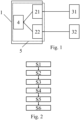
- the automated vehicle 1 schematically shown in figure 1 comprises two receiving units 21, 22 for receiving position information from two positioning systems 31, 32, and a control unit 4 connected to the two receiving units 21, 22, respectively.
- the control unit 4 has a higher automotive safety level than the receiving units 21, 22.
- the receiving units 21, 22 and the control unit 4 form (part of) a data processing system 5 which is configured to carrying out the method for time validation, the method comprising, as can be gathered from the flowchart in figure 2 , substantially six steps S1 - S6.
- a respective local time of the two receiving units 21, 22 is synchronized to a vehicle time, e.g., using PTP.
- a first position information is sent from a first one of the positioning systems 31 and is received at a first one of the receiving units 21, the received first position information comprises a first time information wt1.
- a second position information is sent from a second one of the positioning systems 32 and is received at a second one of the receiving units 22, the received second position information comprises a second time information wt2.
- the first one of the positioning systems 31 is a first global navigation satellite system, e.g., GPS
- the second one of the positioning systems 32 is a second global navigation satellite system, e.g., Beidou. Therefore, the first position information is received from the first global navigation satellite system and the second position information is received from a second global navigation satellite system, wherein the first and the second global navigation satellite system are different from each other.
- the first and the second position information may be received from one or the same global navigation satellite system, i.e., the first one of the positioning systems 31 may send the first and the second position information to the first and/or the second one of the receiving units 31, 32.
- a first timestamp ts1 is provided to the received first position information based on the vehicle time (i.e., synchronized local time of the first one of the receiving units 31) at the time of receiving the first position information by the first one of the receiving units 31, and a second timestamp ts2 is provided to the received second position information based on the vehicle time (i.e., synchronized local time of the first one of the receiving units 32) at the time of receiving the second position information by the second one of the receiving units 32.
- a fourth step S4 of the method the first one of the receiving units 31 sends the first time information wt1 and the first timestamp ts1 to the control unit 4, and the second one of the receiving units 32 sends the second time information wt2 and the first timestamp ts2 to the control unit 4.
- control unit 4 controls, directly or indirectly, an automated driving function of the vehicle 1 based on the received first and/or second position information only when the difference between the first and the second time information wt1, wt2 and the difference between the first and the second timestamp ts1, ts2 are the same and/or if the deviation between the two differences is below the predefined threshold.
Landscapes
- Engineering & Computer Science (AREA)
- Remote Sensing (AREA)
- Radar, Positioning & Navigation (AREA)
- Computer Networks & Wireless Communication (AREA)
- Signal Processing (AREA)
- Mechanical Engineering (AREA)
- Transportation (AREA)
- Human Computer Interaction (AREA)
- Automation & Control Theory (AREA)
- Physics & Mathematics (AREA)
- General Physics & Mathematics (AREA)
- Traffic Control Systems (AREA)
- Position Fixing By Use Of Radio Waves (AREA)
Abstract
Description
- The present disclosure is directed to a method for time validation in a vehicle, to a data processing system comprising means for carrying out the method, a computer program comprising instructions which, when the program is executed by a computer, cause the computer to carry out the method, and a computer-readable medium comprising instructions which, when executed by a computer, cause the computer to carry out the method.
- With an increasing complexity of autonomous or automated vehicles, multiple communication busses are used by different electronic control units (ECUs) to ensure that autonomous or automated driving functions fulfill safety requirements, e.g. requirements needed to fulfill a so called Automotive Safety Integrity Level (ASIL).
- The Automotive Safety Integrity Level is a risk classification scheme defined by ISO 26262 - Functional Safety for Road Vehicles. The ASIL classification comprises four safety levels, starting from ASIL A with the lowest safety requirements to ASIL D having the highest safety requirements. Furthermore, hazards that are identified as QM do not dictate any safety requirements.
- All related controllers which take part in critical decision making of automated driving functions need to have a synchronized time according to the other controllers. Time synchronization for highly automated vehicles, e.g. a car of a SAE Level 3 or
Level 4 or higher (wherein the SAE J3016 standard describes classification and definition of terms for road-bound vehicles with automated driving systems), need to fulfill ASIL B or higher. - In the state of the art, time synchronization of for example an Ethernet bus is done according to IEEE 802.1AS for a TSN (time sensitive network) and IEEE 1588 with respect to the PTP (Precision Time Protocol). However, for time synchronization via PTP there are several measures that can be taken in addition to the respective standards, so that the integrity of the synchronization process and thus the integrity of the distributed time-base can be ensured.
- More specifically, a vehicle may comprise different environment sensors which are configured to provide sensor data with regards to the environment of the vehicle. A control unit within the vehicle may make use of and/or may fuse the sensor data from the different environment sensors to determine an environment model which indicates the position of objects within the environment of the vehicle. The vehicle may then be operated, e.g. within an autonomous driving mode, based on the environment model. The environment sensors may be located in one or more different communications networks or communications bus systems of the vehicle. Example communication bus systems are a Controller Area Network (CAN), notable a CAN-FD (Flexible Data-Rate), bus system, a FlexRay bus system, a Local Interconnect Network (LIN) bus system, a Media Oriented Systems Transport (MOST) bus system and/or an Ethernet bus system.
- The different environment sensors typically each comprise a local time clock which is configured to provide a time stamp for the sensor data which is captured by the respective environment sensor. The time stamps of the sensor data which is provided by the different sensors are typically taken into account when fusing the sensor data to determine the environment model.
- Differences in the local times which are indicated by the local time clocks of the different environment sensors may lead to inaccuracies of the environment model and may impair autonomous driving.
- In this respect,
WO2021204342A1 discloses a method for performing time-synchronization between a master clock of a master unit and a plurality of slave clocks of a corresponding plurality of slave units within a communication bus system. The method comprises sending a forward time-synchronization message indicative of the master clock from the master unit to the plurality of slave units, in order to enable the plurality of slave units to time-synchronize their respective slave clocks with the master clock. The method further comprises receiving a reverse time-synchronization message indicative of the respective slave clock from each of the plurality of slave units at a first validator. In addition, the method comprises time-synchronizing a plurality of validator clocks of the first validator to the corresponding plurality of slave clocks using the reverse time-synchronization messages from the plurality of slave units, and validating the time-synchronization between the plurality of slave clocks at the first validator based on the plurality of validator clocks of the first validator. - Moreover, also GNSS (global navigation satellite system) positioning information are essential for autonomous driving and its time stamping is also part of the above-described safety goal in order to be able to know the time and the location of the vehicle and use this data later on in the sensor fusion ECU and/or to detect a location of the vehicle on a map. To ensure time stamping with ASIL, the state of the art is relaying on ASIL-B receiver (chips) for the GNSS positioning information. This limits the option of receiver (chips) that may be used in automated vehicles. It is for example not possible to relay on QM receivers and a QM receiver ECU for GNSS positioning information.
- Against the background of this prior art, one object of the present disclosure is, inter alia, to provide a device and a method which are suitable for overcoming at least some of the above-mentioned disadvantages of the prior art, respectively.
- The object is solved by the features of the independent claims. The dependent claims contain preferred further developments of the disclosure.
- More specifically, the object is solved by a method for time validation in a vehicle.
- The method may be a computer-implemented method. The method may also be called a method for timestamp validation provided to position information by a data processing unit installed in a vehicle.
- The method comprises receiving a first position information at a receiving unit of the vehicle, the received first position information comprises a first time information.
- The method comprises providing a first timestamp to the received first position information based on a vehicle time at the time of receiving the first position information.
- The method comprises receiving a second position information at a receiving unit of the vehicle, the received second position information comprises a second time information.
- The method comprises providing a second timestamp to the received second position information based on the vehicle time at the time of receiving the second position information.
- The method comprises determining if a difference between the first and the second time information and a difference between the first and the second timestamp are the same and/or if a deviation between the two differences is below a predefined threshold.
- The position information may be received from a satellite navigation or satnav system which is a system that uses satellites to provide autonomous geo-spatial positioning. It allows small electronic receivers to determine their location (longitude, latitude, and/or altitude/elevation) to high precision (e.g., within a few centimetres to metres) using time signals transmitted along a line of sight by radio from satellites. The system can be used for providing position, navigation or for tracking the position of something fitted with a receiver (satellite tracking). The signals also allow the electronic receiver to calculate the current local time to high precision, which allows time synchronization. These uses are collectively known as Positioning, Navigation and Timing (PNT). Satnav systems operate independently of any telephonic or internet reception, though these technologies can enhance the usefulness of the positioning information generated.
- A satellite navigation system with global coverage may be termed a global navigation satellite system (GNSS).
- The position information may be provided by such a GNSS and may also be called GNSS (position) information. A global navigation satellite system, or GNSS, is a system for determining position and navigation on earth and in the air by receiving signals from navigation satellites and pseudolites. GNSS is a collective term for the use of existing and future global satellite systems such as: NAVSTAR GPS (Global Positioning System) of the United States of America, GLONASS (Global Navigation Satellite System) of the Russian Federation, Galileo of the European Union, and Beidou of the People's Republic of China and various supplementary systems of Europe, the USA, Japan and India.
- As described above, the respective positioning information may allow the vehicle to determine its location, e.g. based on a respective time information included in the position information. For example a GPS receiver calculates its own four-dimensional position in spacetime based on data received from multiple GPS satellites. Each satellite carries an accurate record of its position and time, and transmits that data as position information to the receiver. The satellites carry very stable atomic clocks that are synchronized with one another and with ground clocks. Any drift from time maintained on the ground is corrected daily. In the same manner, the satellite locations are known with great precision. The GPS receivers have clocks as well, which use the vehicle, e.g., a global time used by some or all of the communication networks of the vehicle. Since the speed of radio waves is constant and independent of the satellite speed, the time delay between when the satellite transmits a signal and the receiver receives it is proportional to the distance from the satellite to the receiver. At a minimum, four satellites must be in view of the receiver for it to compute four unknown quantities (three position coordinates and the deviation of its own clock from satellite time). However, the time information included in the GPS signal may not only be used to calculate the position coordinates but may also be used to calculate a time difference between two subsequently received GPS signals. When both GPS signals a timestamp at the time of the receiving the GPS signals, a time difference between the two timestamps should be substantially the same, i.e. should be ideally the same but may slightly deviate from the time difference calculated based on the time included in the GPS signals. By checking if the time differences are substantially the same, it may be ensured that no time corruption of the local time used at the receiver unit occurred between receiving the two GPS signals. Therefore, safety integrity may be ensured even if the receiver itself does not provide safety integrity. The description given above applies mutatis mutandis to all other satellite navigation systems and is thus not limited to GPS which was solely used for exemplary purposes.
- In the following, optional further developments of the disclosure are described in detail.
- The receiving unit may provide the first timestamp to the received first position information and/or the second timestamp to the received second position information. That is, the timestamping may be done by the receiving unit, optionally, at the time of receiving the position information. The timestamps may include an actual time of a local clock of the receiving unit.
- The receiving unit may be connected to a control unit of the vehicle. The method may further comprise sending the first and the second time information and the first and the second timestamp from the receiving unit to the control unit, and determining if the difference between the first and the second time information and the difference between the first and the second timestamp are the same and/or if the deviation between the two differences is below the predefined threshold at the control unit.
- That is, when the timestamping was done by the receiving unit, the timestamps may be sent from the receiving unit to the control unit, optionally along with the positioning information, and the control unit may compute the time differences and do the comparing of the computed time differences. This also allows the control unit to act as a central validator for timestamps provided by different sub receiving units, i.e., the receiving unit may comprise a plurality of receiving units for receiving positioning information from different positioning system, e.g., satellite navigation systems. For example, one of the sub receiving units may be provided for GPS and another one of the sub receiving units may be provided for Galileo. The two sub receiving units may provide a timestamp to the position information received from the respective positioning system. The control unit may then carry out time validation between the respective sub receiving units.
- That is, the method may comprise receiving a first position information at a first receiving unit of the vehicle, the received first position information comprises a first time information. The method may comprise providing a first timestamp to the received first position information based on a vehicle time at the time of receiving the first position information. Optionally, the first timestamp is provided by the first receiving unit. The method may comprise receiving a second position information at a second receiving unit of the vehicle, the received second position information comprises a second time information. The method may comprise providing a second timestamp to the received second position information based on the vehicle time at the time of receiving the second position information. Optionally, the second timestamp is provided by the second receiving unit. The method may comprise determining if a difference between the first and the second time information and a difference between the first and the second timestamp are the same and/or if a deviation between the two differences is below a predefined threshold. The first time information may be received from a first positioning system. The second time information may be received from a second positioning system. The first positioning system may be different from the second positioning system. The method may further comprise sending the first and the second time information and the first and the second timestamp from the first and the second receiving unit to the control unit, and determining if the difference between the first and the second time information and the difference between the first and the second timestamp are the same and/or if the deviation between the two differences is below the predefined threshold at the control unit.
- The control unit may have a higher automotive safety level than the receiving unit. That is, the receiving unit may be QM whereas the control unit is ASIL B. As already explained above, the automotive safety integrity level (ASIL) is a risk classification scheme defined by the above-mentioned ISO 26262 - Functional Safety for Road Vehicles standard. This is an adaptation of the Safety Integrity Level (SIL) used in IEC 61508 for the automotive industry. This classification helps defining the safety requirements necessary to be in line with the ISO 26262 standard. The ASIL is established by performing a risk analysis of a potential hazard by looking at the Severity, Exposure and Controllability of the vehicle operating scenario. The safety goal for that hazard in turn carries the ASIL requirements. There are four ASILs identified by the standard: ASIL A, ASIL B, ASIL C, ASIL D. ASIL D dictates the highest integrity requirements on the product and ASIL A the lowest. Hazards that are identified as QM (see below) do not dictate any safety requirements.
- The method may comprise synchronizing a local time of the receiving unit to the vehicle time. For example, PTP may be used to synchronize the receiving unit to a global or master time, i.e., the vehicle time, used by a grandmaster. The receiving unit is acting as a slave to be synchronize to the grandmaster time. If more than one receiving unit is used, every receiving unit may be synchronized to the vehicle time.
- The receiving unit may provide the first timestamp to the received first position information and/or the second timestamp to the received second position information based on its synchronized local time, i.e. based on its time synchronized to global/vehicle time.
- The first position information may be received from a first global navigation satellite system and the second position information is received from a second global navigation satellite system, wherein the first and the second global navigation satellite system are different from each other.
- The first and the second position information may be received from one global navigation satellite system.
- The vehicle may be an automated vehicle. The vehicle may be an automobile, e.g., a car. The automated vehicle can be configured to take over lateral and/or longitudinal guidance of the automated vehicle at least partially and/or temporarily during automated driving. To do so, inter alia the position information validated with the above-described method may be used.
- The automated driving may be such that the driving of the vehicle is (largely) autonomous.
- The vehicle may be a vehicle of
autonomy level 1, i.e., the driver takes over the dynamic driving task, even if supporting systems (e.g., anti-lock braking system (ABS) and/or electronic stability control ESP) are available. - The vehicle may be a vehicle of
autonomy level 1, i.e., have certain driver assistance systems that support the driver in vehicle operation, for example adaptive cruise control (ACC). - The vehicle can be a vehicle of
autonomy level 2, i.e., be partially automated in such a way that functions such as automatic parking, lane keeping or lateral guidance, general longitudinal guidance, acceleration and/or braking are performed by driver assistance systems. - The vehicle may be an autonomy level 3 vehicle, i.e., automated in such a conditional manner that the driver does not need to continuously monitor the system vehicle. The vehicle autonomously performs functions such as triggering the turn signal, changing lanes, and/or lane keeping. The driver can attend to other matters, but is prompted by the system to take over control within a warning time if needed.
- The vehicle may be an
autonomy level 4 vehicle, i.e., so highly automated that the driving of the vehicle is permanently taken over by the system vehicle. If the driving tasks are no longer handled by the system, the driver may be requested to take over control. - The vehicle may be an
autonomy level 5 vehicle, i.e., so fully automated that the driver is not required to complete the driving task. No human intervention is required other than setting the destination and starting the system. The vehicle can operate without a steering wheel or pedals. - The method may comprise controlling an automated driving function of the vehicle based on the received first and/or second position information only when the difference between the first and the second time information and the difference between the first and the second timestamp are the same and/or if the deviation between the two differences is below the predefined threshold.
- Furthermore, a data processing system comprising means for carrying out the above-described method may be provided. The data processing system may be part of the above-described vehicle. It is also possible that a vehicle comprising the data processing system is provided.
- The data processing system may comprise an electronic control unit (ECU), also known as an electronic control module (ECM), which is an embedded system in automotive electronics that controls one or more of the electrical systems or subsystems in a car or other motor vehicle. Modern vehicles have many ECUs, and these can include some or all of the following: engine control module (ECM), powertrain control module (PCM), transmission control module (TCM), brake control module (BCM or EBCM), central control module (CCM), central timing module (CTM), general electronic module (GEM), body control module (BCM), and suspension control module (SCM). These ECUs together are sometimes referred to collectively as the car's computer though technically they are all separate computers, not a single one. Sometimes an assembly incorporates several individual control modules (a PCM often controls both the engine and the transmission). The ECU comprising the first microcontroller may be configured to control functions relevant to a driving behavior of the vehicle, such as an engine control system, a power transmission, a braking system and/or a tire pressure control system. Additionally or alternatively, one, some or all driver assistance systems of the automated vehicle such as parking assistant, adaptive cruise control, lane departure warning, lane change assistant, traffic sign recognition, light signal recognition, approach assistant, night vision assistant, intersection assistant, and/or many others may be controlled by the ECU. The ECU may be or may be part of an (intelligent) processor-controlled unit that can, optionally, communicate with other modules, optionally via a central gateway (CGW). The ECU can form part of the vehicle's onboard network comprising fieldbuses such as CAN bus, LIN bus, MOST bus and/or FlexRay or automotive Ethernet, optionally together with a telematics control unit.
- Moreover, the description given above with respect to the method applies mutatis mutandis to the data processing system vehicle and vice versa.
- Furthermore, a computer program comprising instructions which, when the program is executed by a computer, cause the computer to carry out the above-described method may be provided.
- The program may comprise any program code, in particular a code suitable for control systems of vehicles. The description given above with respect to the method, the data processing system and the vehicle applies mutatis mutandis to the computer program and vice versa.
- Furthermore, a computer-readable medium comprising instructions which, when executed by a computer, cause the computer to carry out the above described method, may be provided.
- The computer-readable medium may be any digital data storage device, such as an USB flash drive, a hard disk, a CD-ROM, a SD card, or a SSD card. The above-described computer program may be stored on the computer-readable medium. However, the computer program does not necessarily have to be stored on such a computer-readable medium but can also be obtained via the Internet.
- Moreover, the description given above with respect to the method and the data processing system applies mutatis mutandis to the computer program and the computer-readable medium, and vice versa.
- The above-described method may be summarized in other words and with respect to a more concrete implementation thereof as follows, wherein the following description is not intended to limit the disclosure in any way: The current state of the art is relaying on ASIL-B receiver chips. However, few available options of ASIL B receiver chips also limit the options for GNSS receiver ECUs. Basic principle of the disclosure is to relay on QM receivers and QM receiver ECUs for GNSS and at the consumer side create safety integrity by performing a plausibility check for time stamping of the GNSS data compared to the world global time received from (optionally) different GNSS systems (and optionally different satellites of each system). More specifically, a GNSS QM ECU may contain several GNSS receivers for different systems. The GNSS data contains world time as well as the positioning information from several satellites of the GNSS. The GNSS receiver ECU micro controller unit (MCU) will get the vehicle global time synchronization by the standard PTP protocol in the vehicle with QM safety integrity. GNSS row data is time stamped with the global vehicle time immediately upon reception. The time stamped GNSS data is sent to higher level positioning ECU, i.e., the GNSS consumer, for further processing with higher safety integrity. The method comprises checking the consistency of flow of time between different satellite system and vehicle time stamps provided by GNSS receiver.
- An embodiment is described with reference to figures land 2 below.
- Fig. 1
- shows schematically an automated vehicle comprising a control unit configured to carry out a method for time validation, and
- Fig. 2
- shows schematically a flowchart of the method.
- The
automated vehicle 1 schematically shown infigure 1 comprises two receivingunits positioning systems control unit 4 connected to the two receivingunits control unit 4 has a higher automotive safety level than the receivingunits - The receiving
units control unit 4 form (part of) adata processing system 5 which is configured to carrying out the method for time validation, the method comprising, as can be gathered from the flowchart infigure 2 , substantially six steps S1 - S6. - In a first step S1 of the method, a respective local time of the two receiving
units - In a second step S2 of the method, a first position information is sent from a first one of the
positioning systems 31 and is received at a first one of the receivingunits 21, the received first position information comprises a first time information wt1. In the first step S1 of the method, a second position information is sent from a second one of thepositioning systems 32 and is received at a second one of the receivingunits 22, the received second position information comprises a second time information wt2. - The first one of the
positioning systems 31 is a first global navigation satellite system, e.g., GPS, and the second one of thepositioning systems 32 is a second global navigation satellite system, e.g., Beidou. Therefore, the first position information is received from the first global navigation satellite system and the second position information is received from a second global navigation satellite system, wherein the first and the second global navigation satellite system are different from each other. Alternatively, the first and the second position information may be received from one or the same global navigation satellite system, i.e., the first one of thepositioning systems 31 may send the first and the second position information to the first and/or the second one of the receivingunits - In a third step S3 of the method, a first timestamp ts1 is provided to the received first position information based on the vehicle time (i.e., synchronized local time of the first one of the receiving units 31) at the time of receiving the first position information by the first one of the receiving
units 31, and a second timestamp ts2 is provided to the received second position information based on the vehicle time (i.e., synchronized local time of the first one of the receiving units 32) at the time of receiving the second position information by the second one of the receivingunits 32. - In a fourth step S4 of the method, the first one of the receiving
units 31 sends the first time information wt1 and the first timestamp ts1 to thecontrol unit 4, and the second one of the receivingunits 32 sends the second time information wt2 and the first timestamp ts2 to thecontrol unit 4. - In a fifth step S5 of the method, the
control unit 4 determines if the difference between the first and the second time information wt1, wt2 and the difference between the first and the second timestamp ts1, ts2 are the same and/or if the deviation between the two differences is below the predefined threshold. This may be calculated as follows: wt2 - wt1 = ts2 - ts1 or (wt2 - wt1) - (ts2 - ts1) < threshold or (wt2 - wt1) - (ts2 - ts1) =< threshold. - In a sixth step S6 of the method, the
control unit 4 controls, directly or indirectly, an automated driving function of thevehicle 1 based on the received first and/or second position information only when the difference between the first and the second time information wt1, wt2 and the difference between the first and the second timestamp ts1, ts2 are the same and/or if the deviation between the two differences is below the predefined threshold. -
- 1
- automated vehicle
- 21, 22
- receiving unit
- 31, 32
- positioning systems
- 4
- control unit
- 5
- data processing system
- S1 - S6
- steps of the method
Claims (12)
- Method for time validation in a vehicle (1), the method comprising:- receiving a first position information at a receiving unit (21, 22) of the vehicle (1), the received first position information comprises a first time information,- providing a first timestamp to the received first position information based on a vehicle time at the time of receiving the first position information,- receiving a second position information at the receiving unit (21, 22) of the vehicle (1), the received second position information comprises a second time information,- providing a second timestamp to the received second position information based on the vehicle time at the time of receiving the second position information, and- determining if a difference between the first and the second time information and a difference between the first and the second timestamp are the same and/or if a deviation between the two differences is below a predefined threshold.
- Method according to claim 1, wherein the receiving unit (21, 22) provides the first timestamp to the received first position information and/or the second timestamp to the received second position information.
- Method according to claim 1 or 2, wherein the receiving unit (21, 22) is connected to a control unit (4) of the vehicle (1), wherein the method further comprises:- sending the first and the second time information and the first and the second timestamp from the receiving unit (21, 22) to the control unit (4), and- determining if the difference between the first and the second time information and the difference between the first and the second timestamp are the same and/or if the deviation between the two differences is below the predefined threshold at the control unit (4).
- Method according to claim 3, wherein the control unit (4) has a higher automotive safety level than the receiving unit (21, 22).
- Method according to any of claims 1 to 4, wherein the method further comprises synchronizing a local time of the receiving unit (21, 22) to the vehicle time.
- Method according to claim 5, when being dependent on any of claims 2 to 4, wherein the receiving unit (21, 22) provides the first timestamp to the received first position information and/or the second timestamp to the received second position information based on its synchronized local time.
- Method according to any of claims 1 to 6, wherein the first position information is received from a first global navigation satellite system (31) and the second position information is received from a second global navigation satellite system (32), wherein the first and the second global navigation satellite system (31, 32) are different from each other.
- Method according to any of claims 1 to 6, wherein the first and the second position information are received from one global navigation satellite system (31, 32).
- Method according to any of claims 1 to 8, wherein the vehicle (1) is an automated vehicle and wherein the method further comprises controlling an automated driving function of the vehicle (1) based on the received first and/or second position information only when the difference between the first and the second time information and the difference between the first and the second timestamp are the same and/or if the deviation between the two differences is below the predefined threshold.
- A data processing system (5) comprising means for carrying out the method according to any of claims 1 to 9.
- A computer program comprising instructions which, when the program is executed by a computer, cause the computer to carry out the method according to any of claims 1 to 9.
- A computer-readable medium comprising instructions which, when executed by a computer, cause the computer to carry out the method according to any of claims 1 to 9.
Priority Applications (4)
| Application Number | Priority Date | Filing Date | Title |
|---|---|---|---|
| EP22169651.1A EP4270825B1 (en) | 2022-04-25 | 2022-04-25 | Method and device for time validation in a vehicle |
| US18/859,915 US20250284009A1 (en) | 2022-04-25 | 2023-03-21 | Method and Device for Time Validation in a Vehicle |
| CN202380034328.2A CN119111045A (en) | 2022-04-25 | 2023-03-21 | Method and device for time verification in a vehicle |
| PCT/EP2023/057140 WO2023208476A1 (en) | 2022-04-25 | 2023-03-21 | Method and device for time validation in a vehicle |
Applications Claiming Priority (1)
| Application Number | Priority Date | Filing Date | Title |
|---|---|---|---|
| EP22169651.1A EP4270825B1 (en) | 2022-04-25 | 2022-04-25 | Method and device for time validation in a vehicle |
Publications (2)
| Publication Number | Publication Date |
|---|---|
| EP4270825A1 true EP4270825A1 (en) | 2023-11-01 |
| EP4270825B1 EP4270825B1 (en) | 2025-01-29 |
Family
ID=81654549
Family Applications (1)
| Application Number | Title | Priority Date | Filing Date |
|---|---|---|---|
| EP22169651.1A Active EP4270825B1 (en) | 2022-04-25 | 2022-04-25 | Method and device for time validation in a vehicle |
Country Status (4)
| Country | Link |
|---|---|
| US (1) | US20250284009A1 (en) |
| EP (1) | EP4270825B1 (en) |
| CN (1) | CN119111045A (en) |
| WO (1) | WO2023208476A1 (en) |
Citations (4)
| Publication number | Priority date | Publication date | Assignee | Title |
|---|---|---|---|---|
| US20150222378A1 (en) * | 2012-08-16 | 2015-08-06 | Continental Teves Ag & Co. Ohg | Method and system for compensating for a time discrepancy |
| CN106130681A (en) * | 2016-07-25 | 2016-11-16 | 广州市国飞信息科技有限公司 | High-accuracy clock synchronization method, module, equipment and system for time dissemination system |
| WO2021204342A1 (en) | 2020-04-06 | 2021-10-14 | Bayerische Motoren Werke Aktiengesellschaft | Method and system for performing time-synchronization between units of a communication bus system |
| WO2021226394A1 (en) * | 2020-05-07 | 2021-11-11 | Qualcomm Incorporated | Facilitating time synchronization functionality at user equipment |
-
2022
- 2022-04-25 EP EP22169651.1A patent/EP4270825B1/en active Active
-
2023
- 2023-03-21 WO PCT/EP2023/057140 patent/WO2023208476A1/en not_active Ceased
- 2023-03-21 US US18/859,915 patent/US20250284009A1/en active Pending
- 2023-03-21 CN CN202380034328.2A patent/CN119111045A/en active Pending
Patent Citations (4)
| Publication number | Priority date | Publication date | Assignee | Title |
|---|---|---|---|---|
| US20150222378A1 (en) * | 2012-08-16 | 2015-08-06 | Continental Teves Ag & Co. Ohg | Method and system for compensating for a time discrepancy |
| CN106130681A (en) * | 2016-07-25 | 2016-11-16 | 广州市国飞信息科技有限公司 | High-accuracy clock synchronization method, module, equipment and system for time dissemination system |
| WO2021204342A1 (en) | 2020-04-06 | 2021-10-14 | Bayerische Motoren Werke Aktiengesellschaft | Method and system for performing time-synchronization between units of a communication bus system |
| WO2021226394A1 (en) * | 2020-05-07 | 2021-11-11 | Qualcomm Incorporated | Facilitating time synchronization functionality at user equipment |
Also Published As
| Publication number | Publication date |
|---|---|
| US20250284009A1 (en) | 2025-09-11 |
| CN119111045A (en) | 2024-12-10 |
| WO2023208476A1 (en) | 2023-11-02 |
| EP4270825B1 (en) | 2025-01-29 |
Similar Documents
| Publication | Publication Date | Title |
|---|---|---|
| US12044532B2 (en) | Sensor plausibility using GPS road information | |
| US9711051B2 (en) | Method of determining the position of a vehicle in a traffic lane of a road and methods for detecting alignment and risk of collision between two vehicles | |
| US12113885B2 (en) | Hardware-based time synchronization for heterogeneous sensors in autonomous vehicles | |
| US8599038B2 (en) | Vehicular wireless communication apparatus and communication system | |
| US8639426B2 (en) | GPS/IMU/video/radar absolute/relative positioning communication/computation sensor platform for automotive safety applications | |
| US8441374B2 (en) | Traveling support device and traveling support method | |
| US20140334477A1 (en) | Method and device for synchronizing network subscribers in an on-board network of a vehicle | |
| KR101814374B1 (en) | Device and method for assigning new data to a digital card | |
| US20210394794A1 (en) | Assessment of a vehicle control system | |
| CN111443327A (en) | Maintaining vehicle position accuracy | |
| CN111915921A (en) | Lane-level precision positioning method using roadside equipment | |
| JP7038830B2 (en) | Satellite-assisted identification method of vehicle position | |
| US20200202638A1 (en) | Information acquisition apparatus, information acquisition method, and non-transitory storage medium storing program | |
| US20200244558A1 (en) | Method system and computer program for communication between electronic control units | |
| US11550066B2 (en) | Method and arrangement for improving global positioning performance of a road vehicle | |
| US11280917B2 (en) | Information processing system, storage medium storing information processing program, and control method | |
| KR102336071B1 (en) | Apparatus for determining position of vehicle and method thereof | |
| US20150222378A1 (en) | Method and system for compensating for a time discrepancy | |
| CN102341833A (en) | driving aids | |
| US20220212665A1 (en) | Driver assistance device | |
| US12085408B2 (en) | Vehicle position estimation device, vehicle position estimation method, and non-transitory recording medium | |
| EP4270825B1 (en) | Method and device for time validation in a vehicle | |
| US20240167824A1 (en) | Method for the localization of a networked motor vehicle | |
| KR20210082422A (en) | Apparatus for determining position of vehicle and method thereof | |
| US20230074566A1 (en) | Driving assistance device, driving assistance method, and non-transitory computer readable medium storing driving assistance program |
Legal Events
| Date | Code | Title | Description |
|---|---|---|---|
| PUAI | Public reference made under article 153(3) epc to a published international application that has entered the european phase |
Free format text: ORIGINAL CODE: 0009012 |
|
| STAA | Information on the status of an ep patent application or granted ep patent |
Free format text: STATUS: THE APPLICATION HAS BEEN PUBLISHED |
|
| AK | Designated contracting states |
Kind code of ref document: A1 Designated state(s): AL AT BE BG CH CY CZ DE DK EE ES FI FR GB GR HR HU IE IS IT LI LT LU LV MC MK MT NL NO PL PT RO RS SE SI SK SM TR |
|
| STAA | Information on the status of an ep patent application or granted ep patent |
Free format text: STATUS: REQUEST FOR EXAMINATION WAS MADE |
|
| 17P | Request for examination filed |
Effective date: 20240418 |
|
| RBV | Designated contracting states (corrected) |
Designated state(s): AL AT BE BG CH CY CZ DE DK EE ES FI FR GB GR HR HU IE IS IT LI LT LU LV MC MK MT NL NO PL PT RO RS SE SI SK SM TR |
|
| REG | Reference to a national code |
Ref country code: DE Ref legal event code: R079 Ipc: H04J0003140000 Ref document number: 602022009946 Country of ref document: DE Free format text: PREVIOUS MAIN CLASS: H04J0003060000 |
|
| GRAP | Despatch of communication of intention to grant a patent |
Free format text: ORIGINAL CODE: EPIDOSNIGR1 |
|
| STAA | Information on the status of an ep patent application or granted ep patent |
Free format text: STATUS: GRANT OF PATENT IS INTENDED |
|
| RIC1 | Information provided on ipc code assigned before grant |
Ipc: H04J 3/06 20060101ALI20240812BHEP Ipc: H04J 3/14 20060101AFI20240812BHEP |
|
| INTG | Intention to grant announced |
Effective date: 20240906 |
|
| GRAS | Grant fee paid |
Free format text: ORIGINAL CODE: EPIDOSNIGR3 |
|
| GRAA | (expected) grant |
Free format text: ORIGINAL CODE: 0009210 |
|
| STAA | Information on the status of an ep patent application or granted ep patent |
Free format text: STATUS: THE PATENT HAS BEEN GRANTED |
|
| AK | Designated contracting states |
Kind code of ref document: B1 Designated state(s): AL AT BE BG CH CY CZ DE DK EE ES FI FR GB GR HR HU IE IS IT LI LT LU LV MC MK MT NL NO PL PT RO RS SE SI SK SM TR |
|
| REG | Reference to a national code |
Ref country code: GB Ref legal event code: FG4D |
|
| REG | Reference to a national code |
Ref country code: CH Ref legal event code: EP |
|
| REG | Reference to a national code |
Ref country code: DE Ref legal event code: R096 Ref document number: 602022009946 Country of ref document: DE |
|
| REG | Reference to a national code |
Ref country code: IE Ref legal event code: FG4D |
|
| REG | Reference to a national code |
Ref country code: NL Ref legal event code: MP Effective date: 20250129 |
|
| PG25 | Lapsed in a contracting state [announced via postgrant information from national office to epo] |
Ref country code: NL Free format text: LAPSE BECAUSE OF FAILURE TO SUBMIT A TRANSLATION OF THE DESCRIPTION OR TO PAY THE FEE WITHIN THE PRESCRIBED TIME-LIMIT Effective date: 20250129 |
|
| PG25 | Lapsed in a contracting state [announced via postgrant information from national office to epo] |
Ref country code: RS Free format text: LAPSE BECAUSE OF FAILURE TO SUBMIT A TRANSLATION OF THE DESCRIPTION OR TO PAY THE FEE WITHIN THE PRESCRIBED TIME-LIMIT Effective date: 20250429 |
|
| PG25 | Lapsed in a contracting state [announced via postgrant information from national office to epo] |
Ref country code: FI Free format text: LAPSE BECAUSE OF FAILURE TO SUBMIT A TRANSLATION OF THE DESCRIPTION OR TO PAY THE FEE WITHIN THE PRESCRIBED TIME-LIMIT Effective date: 20250129 |
|
| PG25 | Lapsed in a contracting state [announced via postgrant information from national office to epo] |
Ref country code: PL Free format text: LAPSE BECAUSE OF FAILURE TO SUBMIT A TRANSLATION OF THE DESCRIPTION OR TO PAY THE FEE WITHIN THE PRESCRIBED TIME-LIMIT Effective date: 20250129 |
|
| PGFP | Annual fee paid to national office [announced via postgrant information from national office to epo] |
Ref country code: DE Payment date: 20250408 Year of fee payment: 4 |
|
| PG25 | Lapsed in a contracting state [announced via postgrant information from national office to epo] |
Ref country code: ES Free format text: LAPSE BECAUSE OF FAILURE TO SUBMIT A TRANSLATION OF THE DESCRIPTION OR TO PAY THE FEE WITHIN THE PRESCRIBED TIME-LIMIT Effective date: 20250129 |
|
| REG | Reference to a national code |
Ref country code: LT Ref legal event code: MG9D |
|
| PG25 | Lapsed in a contracting state [announced via postgrant information from national office to epo] |
Ref country code: NO Free format text: LAPSE BECAUSE OF FAILURE TO SUBMIT A TRANSLATION OF THE DESCRIPTION OR TO PAY THE FEE WITHIN THE PRESCRIBED TIME-LIMIT Effective date: 20250429 Ref country code: IS Free format text: LAPSE BECAUSE OF FAILURE TO SUBMIT A TRANSLATION OF THE DESCRIPTION OR TO PAY THE FEE WITHIN THE PRESCRIBED TIME-LIMIT Effective date: 20250529 |
|
| PGFP | Annual fee paid to national office [announced via postgrant information from national office to epo] |
Ref country code: IT Payment date: 20250430 Year of fee payment: 4 |
|
| REG | Reference to a national code |
Ref country code: AT Ref legal event code: MK05 Ref document number: 1764497 Country of ref document: AT Kind code of ref document: T Effective date: 20250129 |
|
| PG25 | Lapsed in a contracting state [announced via postgrant information from national office to epo] |
Ref country code: HR Free format text: LAPSE BECAUSE OF FAILURE TO SUBMIT A TRANSLATION OF THE DESCRIPTION OR TO PAY THE FEE WITHIN THE PRESCRIBED TIME-LIMIT Effective date: 20250129 |
|
| PG25 | Lapsed in a contracting state [announced via postgrant information from national office to epo] |
Ref country code: LV Free format text: LAPSE BECAUSE OF FAILURE TO SUBMIT A TRANSLATION OF THE DESCRIPTION OR TO PAY THE FEE WITHIN THE PRESCRIBED TIME-LIMIT Effective date: 20250129 Ref country code: PT Free format text: LAPSE BECAUSE OF FAILURE TO SUBMIT A TRANSLATION OF THE DESCRIPTION OR TO PAY THE FEE WITHIN THE PRESCRIBED TIME-LIMIT Effective date: 20250529 |
|
| PGFP | Annual fee paid to national office [announced via postgrant information from national office to epo] |
Ref country code: FR Payment date: 20250422 Year of fee payment: 4 |
|
| PG25 | Lapsed in a contracting state [announced via postgrant information from national office to epo] |
Ref country code: GR Free format text: LAPSE BECAUSE OF FAILURE TO SUBMIT A TRANSLATION OF THE DESCRIPTION OR TO PAY THE FEE WITHIN THE PRESCRIBED TIME-LIMIT Effective date: 20250430 Ref country code: BG Free format text: LAPSE BECAUSE OF FAILURE TO SUBMIT A TRANSLATION OF THE DESCRIPTION OR TO PAY THE FEE WITHIN THE PRESCRIBED TIME-LIMIT Effective date: 20250129 |
|
| PG25 | Lapsed in a contracting state [announced via postgrant information from national office to epo] |
Ref country code: AT Free format text: LAPSE BECAUSE OF FAILURE TO SUBMIT A TRANSLATION OF THE DESCRIPTION OR TO PAY THE FEE WITHIN THE PRESCRIBED TIME-LIMIT Effective date: 20250129 |
|
| PG25 | Lapsed in a contracting state [announced via postgrant information from national office to epo] |
Ref country code: SE Free format text: LAPSE BECAUSE OF FAILURE TO SUBMIT A TRANSLATION OF THE DESCRIPTION OR TO PAY THE FEE WITHIN THE PRESCRIBED TIME-LIMIT Effective date: 20250129 |
|
| PG25 | Lapsed in a contracting state [announced via postgrant information from national office to epo] |
Ref country code: SM Free format text: LAPSE BECAUSE OF FAILURE TO SUBMIT A TRANSLATION OF THE DESCRIPTION OR TO PAY THE FEE WITHIN THE PRESCRIBED TIME-LIMIT Effective date: 20250129 |
|
| PG25 | Lapsed in a contracting state [announced via postgrant information from national office to epo] |
Ref country code: DK Free format text: LAPSE BECAUSE OF FAILURE TO SUBMIT A TRANSLATION OF THE DESCRIPTION OR TO PAY THE FEE WITHIN THE PRESCRIBED TIME-LIMIT Effective date: 20250129 |
|
| PG25 | Lapsed in a contracting state [announced via postgrant information from national office to epo] |
Ref country code: EE Free format text: LAPSE BECAUSE OF FAILURE TO SUBMIT A TRANSLATION OF THE DESCRIPTION OR TO PAY THE FEE WITHIN THE PRESCRIBED TIME-LIMIT Effective date: 20250129 Ref country code: CZ Free format text: LAPSE BECAUSE OF FAILURE TO SUBMIT A TRANSLATION OF THE DESCRIPTION OR TO PAY THE FEE WITHIN THE PRESCRIBED TIME-LIMIT Effective date: 20250129 |
|
| PG25 | Lapsed in a contracting state [announced via postgrant information from national office to epo] |
Ref country code: RO Free format text: LAPSE BECAUSE OF FAILURE TO SUBMIT A TRANSLATION OF THE DESCRIPTION OR TO PAY THE FEE WITHIN THE PRESCRIBED TIME-LIMIT Effective date: 20250129 |
|
| PG25 | Lapsed in a contracting state [announced via postgrant information from national office to epo] |
Ref country code: SK Free format text: LAPSE BECAUSE OF FAILURE TO SUBMIT A TRANSLATION OF THE DESCRIPTION OR TO PAY THE FEE WITHIN THE PRESCRIBED TIME-LIMIT Effective date: 20250129 |
|
| REG | Reference to a national code |
Ref country code: DE Ref legal event code: R097 Ref document number: 602022009946 Country of ref document: DE |
|
| REG | Reference to a national code |
Ref country code: CH Ref legal event code: H13 Free format text: ST27 STATUS EVENT CODE: U-0-0-H10-H13 (AS PROVIDED BY THE NATIONAL OFFICE) Effective date: 20251125 |
|
| PLBE | No opposition filed within time limit |
Free format text: ORIGINAL CODE: 0009261 |
|
| STAA | Information on the status of an ep patent application or granted ep patent |
Free format text: STATUS: NO OPPOSITION FILED WITHIN TIME LIMIT |
|
| PG25 | Lapsed in a contracting state [announced via postgrant information from national office to epo] |
Ref country code: LU Free format text: LAPSE BECAUSE OF NON-PAYMENT OF DUE FEES Effective date: 20250425 |
|
| PG25 | Lapsed in a contracting state [announced via postgrant information from national office to epo] |
Ref country code: MC Free format text: LAPSE BECAUSE OF FAILURE TO SUBMIT A TRANSLATION OF THE DESCRIPTION OR TO PAY THE FEE WITHIN THE PRESCRIBED TIME-LIMIT Effective date: 20250129 |
|
| REG | Reference to a national code |
Ref country code: BE Ref legal event code: MM Effective date: 20250430 |
|
| 26N | No opposition filed |
Effective date: 20251030 |
|
| PG25 | Lapsed in a contracting state [announced via postgrant information from national office to epo] |
Ref country code: BE Free format text: LAPSE BECAUSE OF NON-PAYMENT OF DUE FEES Effective date: 20250430 |
|
| PG25 | Lapsed in a contracting state [announced via postgrant information from national office to epo] |
Ref country code: CH Free format text: LAPSE BECAUSE OF NON-PAYMENT OF DUE FEES Effective date: 20250430 |
|
| PGFP | Annual fee paid to national office [announced via postgrant information from national office to epo] |
Ref country code: GB Payment date: 20260324 Year of fee payment: 5 |
|
| PG25 | Lapsed in a contracting state [announced via postgrant information from national office to epo] |
Ref country code: IE Free format text: LAPSE BECAUSE OF NON-PAYMENT OF DUE FEES Effective date: 20250425 |