EP4270676A1 - Contact insulators for use with differential pairs of contacts and method of termination - Google Patents
Contact insulators for use with differential pairs of contacts and method of termination Download PDFInfo
- Publication number
- EP4270676A1 EP4270676A1 EP23170514.6A EP23170514A EP4270676A1 EP 4270676 A1 EP4270676 A1 EP 4270676A1 EP 23170514 A EP23170514 A EP 23170514A EP 4270676 A1 EP4270676 A1 EP 4270676A1
- Authority
- EP
- European Patent Office
- Prior art keywords
- contact
- contacts
- insulator
- receiving
- conductor
- Prior art date
- Legal status (The legal status is an assumption and is not a legal conclusion. Google has not performed a legal analysis and makes no representation as to the accuracy of the status listed.)
- Granted
Links
Images


Classifications
-
- H—ELECTRICITY
- H01—ELECTRIC ELEMENTS
- H01R—ELECTRICALLY-CONDUCTIVE CONNECTIONS; STRUCTURAL ASSOCIATIONS OF A PLURALITY OF MUTUALLY-INSULATED ELECTRICAL CONNECTING ELEMENTS; COUPLING DEVICES; CURRENT COLLECTORS
- H01R13/00—Details of coupling devices of the kinds covered by groups H01R12/70 or H01R24/00 - H01R33/00
- H01R13/40—Securing contact members in or to a base or case; Insulating of contact members
-
- H—ELECTRICITY
- H01—ELECTRIC ELEMENTS
- H01R—ELECTRICALLY-CONDUCTIVE CONNECTIONS; STRUCTURAL ASSOCIATIONS OF A PLURALITY OF MUTUALLY-INSULATED ELECTRICAL CONNECTING ELEMENTS; COUPLING DEVICES; CURRENT COLLECTORS
- H01R13/00—Details of coupling devices of the kinds covered by groups H01R12/70 or H01R24/00 - H01R33/00
- H01R13/46—Bases; Cases
- H01R13/516—Means for holding or embracing insulating body, e.g. casing, hoods
- H01R13/518—Means for holding or embracing insulating body, e.g. casing, hoods for holding or embracing several coupling parts, e.g. frames
-
- H—ELECTRICITY
- H01—ELECTRIC ELEMENTS
- H01B—CABLES; CONDUCTORS; INSULATORS; SELECTION OF MATERIALS FOR THEIR CONDUCTIVE, INSULATING OR DIELECTRIC PROPERTIES
- H01B11/00—Communication cables or conductors
- H01B11/02—Cables with twisted pairs or quads
- H01B11/04—Cables with twisted pairs or quads with pairs or quads mutually positioned to reduce cross-talk
-
- H—ELECTRICITY
- H01—ELECTRIC ELEMENTS
- H01R—ELECTRICALLY-CONDUCTIVE CONNECTIONS; STRUCTURAL ASSOCIATIONS OF A PLURALITY OF MUTUALLY-INSULATED ELECTRICAL CONNECTING ELEMENTS; COUPLING DEVICES; CURRENT COLLECTORS
- H01R13/00—Details of coupling devices of the kinds covered by groups H01R12/70 or H01R24/00 - H01R33/00
- H01R13/62—Means for facilitating engagement or disengagement of coupling parts or for holding them in engagement
- H01R13/629—Additional means for facilitating engagement or disengagement of coupling parts, e.g. aligning or guiding means, levers, gas pressure electrical locking indicators, manufacturing tolerances
-
- H—ELECTRICITY
- H01—ELECTRIC ELEMENTS
- H01R—ELECTRICALLY-CONDUCTIVE CONNECTIONS; STRUCTURAL ASSOCIATIONS OF A PLURALITY OF MUTUALLY-INSULATED ELECTRICAL CONNECTING ELEMENTS; COUPLING DEVICES; CURRENT COLLECTORS
- H01R13/00—Details of coupling devices of the kinds covered by groups H01R12/70 or H01R24/00 - H01R33/00
- H01R13/646—Details of coupling devices of the kinds covered by groups H01R12/70 or H01R24/00 - H01R33/00 specially adapted for high-frequency, e.g. structures providing an impedance match or phase match
- H01R13/6461—Means for preventing cross-talk
- H01R13/6463—Means for preventing cross-talk using twisted pairs of wires
-
- H—ELECTRICITY
- H01—ELECTRIC ELEMENTS
- H01R—ELECTRICALLY-CONDUCTIVE CONNECTIONS; STRUCTURAL ASSOCIATIONS OF A PLURALITY OF MUTUALLY-INSULATED ELECTRICAL CONNECTING ELEMENTS; COUPLING DEVICES; CURRENT COLLECTORS
- H01R13/00—Details of coupling devices of the kinds covered by groups H01R12/70 or H01R24/00 - H01R33/00
- H01R13/648—Protective earth or shield arrangements on coupling devices, e.g. anti-static shielding
- H01R13/658—High frequency shielding arrangements, e.g. against EMI [Electro-Magnetic Interference] or EMP [Electro-Magnetic Pulse]
- H01R13/6581—Shield structure
-
- H—ELECTRICITY
- H01—ELECTRIC ELEMENTS
- H01R—ELECTRICALLY-CONDUCTIVE CONNECTIONS; STRUCTURAL ASSOCIATIONS OF A PLURALITY OF MUTUALLY-INSULATED ELECTRICAL CONNECTING ELEMENTS; COUPLING DEVICES; CURRENT COLLECTORS
- H01R24/00—Two-part coupling devices, or either of their cooperating parts, characterised by their overall structure
- H01R24/38—Two-part coupling devices, or either of their cooperating parts, characterised by their overall structure having concentrically or coaxially arranged contacts
- H01R24/40—Two-part coupling devices, or either of their cooperating parts, characterised by their overall structure having concentrically or coaxially arranged contacts specially adapted for high frequency
-
- H—ELECTRICITY
- H01—ELECTRIC ELEMENTS
- H01R—ELECTRICALLY-CONDUCTIVE CONNECTIONS; STRUCTURAL ASSOCIATIONS OF A PLURALITY OF MUTUALLY-INSULATED ELECTRICAL CONNECTING ELEMENTS; COUPLING DEVICES; CURRENT COLLECTORS
- H01R13/00—Details of coupling devices of the kinds covered by groups H01R12/70 or H01R24/00 - H01R33/00
- H01R13/46—Bases; Cases
- H01R13/502—Bases; Cases composed of different pieces
- H01R13/506—Bases; Cases composed of different pieces assembled by snap action of the parts
-
- H—ELECTRICITY
- H01—ELECTRIC ELEMENTS
- H01R—ELECTRICALLY-CONDUCTIVE CONNECTIONS; STRUCTURAL ASSOCIATIONS OF A PLURALITY OF MUTUALLY-INSULATED ELECTRICAL CONNECTING ELEMENTS; COUPLING DEVICES; CURRENT COLLECTORS
- H01R24/00—Two-part coupling devices, or either of their cooperating parts, characterised by their overall structure
- H01R24/86—Parallel contacts arranged about a common axis
-
- H—ELECTRICITY
- H01—ELECTRIC ELEMENTS
- H01R—ELECTRICALLY-CONDUCTIVE CONNECTIONS; STRUCTURAL ASSOCIATIONS OF A PLURALITY OF MUTUALLY-INSULATED ELECTRICAL CONNECTING ELEMENTS; COUPLING DEVICES; CURRENT COLLECTORS
- H01R43/00—Apparatus or processes specially adapted for manufacturing, assembling, maintaining, or repairing of line connectors or current collectors or for joining electric conductors
- H01R43/20—Apparatus or processes specially adapted for manufacturing, assembling, maintaining, or repairing of line connectors or current collectors or for joining electric conductors for assembling or disassembling contact members with insulating base, case or sleeve
Definitions
- the present invention relates to contact insulators which are used to properly position differential pairs of contacts in a connector assembly.
- the present invention is also directed to a method of positioning the differential pairs of contacts in the contact insulators.
- contacts are seated into an insulator housing which is assembled into a metallic shell.
- the contacts are crimped to signal conductors from cables, such as, Cat6a cables.
- the contacts need to be seated into the insulator housing for proper location.
- the insulator housing is generally a single housing with a circular cross section.
- the contacts are positioned in contact receiving cavities which are positioned about the outer circumference of the insulator housing. With all contacts needing to be held in place in the same insulator housing at the same time, any movements to orient the insulator housing in such a way as to view another side of the insulator housing to facilitate the positioning of additional contacts in the contact receiving cavities can dislodge the contacts that have already been seated. This is particularly true when dealing with contacts that are attached to stiff or twisted conductors, such as Cat6a signal conductors, as the contacts and conductors do not stay in place.
- the solution is provided by a contact insulator for use with high speed cable with differential pairs of contacts.
- the contact insulator has a contact receiving portion with a first closed side, a second closed side and a third open side.
- a conductor receiving portion has a first closed side, an oppositely facing second open side.
- a transition portion is positioned between the contact receiving portion and the conductor receiving portion.
- Two contact receiving slots are provided in the contact receiving portion, the contact receiving slots extend from a mating end of the contact insulator to the transition portion.
- Two conductor receiving slots are provided in the conductor receiving portion, the conductor receiving slots extend from a conductor receiving end of the contact insulator to the transition portion.
- the second open side and the conductor receiving slots of the conductor receiving portion open in an opposite direction as the open third side and the contact receiving slots of the contact receiving portion.
- the transition portion has a contact receiving opening which extends through the contact insulator from the second open side of the conductor receiving portion to the open third side of the contact receiving portion.
- the contact receiving opening is dimensioned to allow the contacts to be inserted therethrough.
- An object of the present invention is to provide segmented contact insulators which cooperate with differential pairs of contacts to properly secure the contacts in the contact insulators and to allow for the contacts to be easily inserted into the contact insulators, thereby decreases assembly time and difficulty.
- An object of the present invention is to provide a method to insert the contacts in the contact insulators which properly secures the contacts in the contact insulators and decreases assembly time and difficulty.
- An object of the present invention is to provide a means for removing the contacts from the contact insulators without damaging the contacts. This allows the contacts to be reorganized as needed for correct signal pair orientation without damaging signal contacts or the contact insulators.
- An embodiment is directed to a contact insulator for use with high speed cable with differential pairs of contacts.
- the contact insulator has a contact receiving portion with a first closed side, a second closed side and a third open side.
- a conductor receiving portion has a first closed side, an oppositely facing second open side.
- a transition portion is positioned between the contact receiving portion and the conductor receiving portion.
- Two contact receiving slots are provided in the contact receiving portion, the contact receiving slots extend from a mating end of the contact insulator to the transition portion.
- Two conductor receiving slots are provided in the conductor receiving portion, the conductor receiving slots extend from a conductor receiving end of the contact insulator to the transition portion.
- the second open side and the conductor receiving slots of the conductor receiving portion open in an opposite direction as the open third side and the contact receiving slots of the contact receiving portion.
- the transition portion has a contact receiving opening which extends through the contact insulator from the second open side of the conductor receiving portion to the open third side of the contact receiving portion.
- the contact receiving opening is dimensioned to allow the contacts to be inserted therethrough.
- An embodiment is directed to a contact insulator for use with high speed cable with differential pairs of contacts.
- the contact insulator includes a contact receiving portion and a conductor receiving portion.
- the contact receiving portion has contact receiving slots for receiving the contact therein.
- the contact receiving slots open from a first side of the contact insulator.
- the conductor receiving portion has conductor receiving slots for receiving the signal conductors therein.
- the conductor receiving slots open from a second side of the contact insulator.
- a transition portion is positioned between the contact receiving portion and the conductor receiving portion.
- the transition portion has a contact receiving opening which extends through the contact insulator.
- the contact receiving opening is dimensioned to allow the contacts to be inserted therethrough.
- the contact insulator is rotated about the contacts and the signal conductors to position the contacts in the contact receiving slots through the first side of the contact insulator and position the signal conductor in the conductor receiving slots through the second side of the contact insulator.
- An embodiment is directed to a method of terminating a differential pair of contacts to a contact insulator, the contact insulator having a contact receiving portion with contact receiving slots extending from a front of the contact insulator, a conductor receiving portion with conductor receiving slots extending from a rear of the contact insulator, and a transition portion with a contact receiving opening, the contact receiving slots opening in a opposite direction from the conductor receiving slots.
- the method includes: positioning contacts attached to signal conductors proximate the conductor receiving slots at the rear of the contact insulator; inserting the contact through the contact receiving opening; rotating the contact insulator relative to the contacts and the signal conductor; and positioning the contacts in the contact receiving slots and positioning the signal conductors in the conductor receiving slots.
- an electrical connector assembly 10 has a shell housing 12 and a crosstalk shield 14.
- the connector assembly 10 may be a plug connector assembly or a receptacle connector assembly.
- the shell housing 12 has a mating end 20 and a conductor receiving end 22.
- the shell housing 12 has a mating portion 24 proximate the mating end 20.
- the mating portion 24 has a smaller outside diameter D1 than the remainder of the shell housing 12.
- the mating portion 24 has a contact receiving opening 23 with an inner or inside wall 25 which extends circumferentially around the opening 23.
- other configurations of the shell housing 12 may be used.
- a recessed portion 26 is provided on the shell housing 12 proximate the conductor receiving end 22.
- the recessed portion 26 has multiple projections 28 which extend from the surface thereof.
- the recessed portion 26 has an outer diameter of D2, which is larger than the outside diameter D1 of the mating portion 24.
- a shoulder 30 extends circumferentially around the conductor receiving end 22 of the shell housing 12. The shoulder 30 is provided at one end of the recessed portion 26.
- other configurations of the shell housing 12 may be used.
- Crosstalk shield receiving recesses or slots 32 extend from the conductor receiving end 22 toward the mating end 20.
- the crosstalk shield receiving slots 32 extend through the shoulder 30 and into the recessed portion 26.
- four crosstalk shield receiving slots 32 are provided to accommodate the configuration of the crosstalk shield 14.
- other numbers of crosstalk shield receiving slots 32 may be used to accommodate different configurations of the crosstalk shield 14.
- the crosstalk shield 14 has a first shield member 40 and a second shield member 42.
- the first shield member 40 and the second shield member 42 are made from nickel silver material, however, other materials, including corrosion resistant materials, may be used which exhibit the shielding characteristics required.
- the connector assembly 10 including the shell housing 12 and the crosstalk shield 14 are illustrative. Other types and configurations of the connector assembly 10 may be used.
- a high speed cable 60 with differential pairs of signal conductors 61 is terminated to the shield housing 12 of the connector assembly 10.
- the signal conductors 61 have contacts 63 terminated thereto.
- four pairs, or eight contacts 63 are shown.
- Each of the differential pairs of contacts 63 are positioned in respective contact spacers or insulators 65 and the contact spacers or insulators 65 are positioned in the contact receiving cavities 53 defined by the first shield member 40 and the second shield member 42 of the crosstalk shield 14.
- the contact insulators 65 accommodates only a portion of the total number of contacts 63 and signal conductors 61, the contact insulators 65 are segmented or modular in nature, as more than one contact insulator 65 is needed to fully isolate the contacts 63 and signal conductors 61.
- Each contact insulator 65 has a contact receiving portion 66 and a conductor receiving portion 68.
- a transition portion 70 is positioned between the contact receiving portion 66 and the conductor receiving portion 68.
- the contact receiving portion 66 has a generally triangular configuration with a first closed wall or side 71, a second closed wall or side 72 and a third open side 73.
- first closed side 71 and the second closed side 72 are positioned proximate the first shield member 40 and the second shield member 42.
- the open third side 73 is positioned proximate the inside wall 25 of the mating portion 24.
- the open third side 73 is necessitated to allow the contacts 63 to be properly inserted into the contact insulator 65.
- a mating wall 67 extends at a mating end 75 of the contact receiving portion 66.
- the mating wall 67 extends between the first closed wall or side 71, the second closed wall or side 72 and the third open side 73.
- Mating contact receiving openings 69 extend through the mating wall 67.
- the mating wall 67 may have a different configuration or may not be present.
- two contact receiving slots 74 are provided in the contact receiving portion 66 of each contact insulator 65.
- the contact receiving slots 74 extend from the mating end 75 of the contact insulator 65 to the transition portion 70.
- the contact receiving slots 74 open to the first side or front of the contact insulator 65 or the third open side 73.
- the contact receiving slots 74 are spaced from each other by an insulative wall 91 and extend essentially parallel to each other. Retention projections 75 extend into each of the contact receiving slots 74.
- An access opening 76 is provided in each of the contact receiving slots 74 in the contact receiving portion 66.
- the openings extend through one or both of the first closed side 71 or the second closed side 72 and extend into the contact receiving slots 74.
- the access openings 76 are in line with the retention projections 75.
- the access openings 76 are dimensioned to receive a removal tool (not shown) therein to facilitate the removal of the contacts 63 from the contact receiving slots 74 when desired.
- the conductor receiving portion 68 has a first closed wall or side 77, an oppositely facing second open side 78.
- Two conductor receiving slots 79 are provided in the conductor receiving portion 68 of each contact insulator 65.
- the conductor receiving slots 79 extend from a conductor receiving end 80 of the contact insulator 65 to the transition portion 70.
- the conductor receiving slots 79 open to the second side or rear of the contact insulator 65 or the second open side 78.
- the conductor receiving slots 79 are spaced from each other by an insulative wall 81 and extend essentially parallel to each other.
- the second open side 78 and the conductor receiving slots 79 of the conductor receiving portion 68 open in an opposite direction as or to the open third side 73 and the contact receiving slots 74 of the contact receiving portion 66.
- the transition portion 70 has a contact receiving cavity or opening 82 which extends through the contact insulator 65 from the second open side 78 of the conductor receiving portion 68 to the open third side 73 of the contact receiving portion 66.
- the contact receiving opening 82 is dimensioned to allow two contacts 63 to be inserted therethrough.
- a retention latch 83 is provided on the transition portion 70.
- the retention latch 83 extends into the contact receiving opening 82 but does not prevent the insertion of the contact 63 through the contact receiving opening 82.
- the contacts 63 are first terminated to the signal conductors 61.
- the contacts 63 can be terminated to the signal conductors 61 using known methods of termination.
- a pair of contacts 63 are moved into the position proximate the rear of the contact insulator 65 proximate the second open side 78 of the conductor receiving slots 79 of the conductor receiving portion 68, as shown in FIG. 4 .
- the contacts 63 are then inserted through the contact receiving cavity or opening 82 in the direction of arrow 84. Although the two contacts 63 are shown being inserted at the same time, each contact 63 may be inserted individually.
- the contact insulator 65 is rotated in the direction of the arrows 85 and 87 shown in FIG. 5 .
- the contacts 63 and signal conductors 61 may be rotate relative to the contact insulator 65.
- the contacts 63 are moved into the contact receiving slots 74 of the conductor receiving portion 68. Rotation continues until the contacts 63 are fully seated in the contact receiving slots 74, as shown in FIG 1 . In this position, the retention projections 75 in each of the contact receiving slots 74 frictionally engages the contacts 63 to physically retain the contacts 63 in the contact receiving slots 74. As rotation occurs, the signal conductors 61 are also moved into position in in the conductor receiving slots 79 of the conductor receiving portion 68.
- the contacts 63 are positioned in the contact receiving slots 74 through the open third side 73 of the contact receiving portion 66.
- the signal conductors 61 are positioned in the conductor receiving slots 79 through the second open side 78 of the conductor receiving slots 79.
- the positioning of the contacts 63 and the signal conductors 61 in both the contact receiving slots 74 and the conductor receiving slots 79 prevents the contacts 63 and signal conductors 61 from being removed without undergoing a rotating or pivoting motion. This adds to the stability of the positioning of the contacts 63 in the contact receiving slots 74 and the signal conductors 61 in the conductor receiving slots 79.
- each contact insulator 65 is configured to house two contacts 63. As eight signal contacts 63 are shown ( FIG.6 ), with four differential pairs of contacts 63, four contact insulators 65 are used to terminate the cable. The same process is used to terminate each of the differential pairs of contacts 63.
- the contacts 63 are inserted through the rear of the contact insulator 65 to provide a way to easily manage the installation steps.
- the signal conductors 61 are not able to move to the outer edges of the contact insulators 65, making it easier to gather the signal conductors 61 together during installation into the shell.
- the contact insulators 65 are inserted into respective contact receiving cavities 53 defined by the first shield member 40 and the second shield member 42 of the crosstalk shield 14.
- the retention latches 83 cooperate with the shell housing 12 to retain the contact insulators 65 in the shell housing 12 of the connector assembly 10.
- contacts 63 will need to be removed from the contact insulator 65 after they are fully seated.
- a small diameter tool (not shown) is inserted into the access opening 76. The tool can be used to push the contact 63 past the retention projections 75 in the contact receiving slot 74, thereby releasing the contact 63 from the contact receiving slot 74.
- the access opening 76 is located directly in line and behind the retention projections 75 there is no moment applied to the contact 63 by the tool and the contact 63 can be pushed directly past the retention projections 75 with no damage to the contacts 63 or the retention projections 75.
- the contacts 63 can be more selectively repaired without disturbing the other pairs already seated.
- the contact insulators 65 of the present invention facilitates the controlled manipulation of the signal conductors 61, as many signal conductors 61, such as, but not limited to, Cat6a conductor are inherently twisted and tend to move wherever they want while assembly occurs. Creating a way to manage the signal conductors 61 with features in the contact insulators 65 decreases assembly time and difficulty. With the signal conductors 61 and contacts 63 on opposite sides of the contact insulator 65, simple relative movements are not able to dislodge the contacts 63.
- the use of the access opening 76 allows for the reorganization of the contacts 63 for correct signal pair orientation without damaging the contacts 63 or the contact insulators 65. This facilitates an easier and more simplified installation process.
Landscapes
- Details Of Connecting Devices For Male And Female Coupling (AREA)
Abstract
Description
- The present invention relates to contact insulators which are used to properly position differential pairs of contacts in a connector assembly. The present invention is also directed to a method of positioning the differential pairs of contacts in the contact insulators.
- With many high speed connectors, contacts are seated into an insulator housing which is assembled into a metallic shell. The contacts are crimped to signal conductors from cables, such as, Cat6a cables. The contacts need to be seated into the insulator housing for proper location. The insulator housing is generally a single housing with a circular cross section. The contacts are positioned in contact receiving cavities which are positioned about the outer circumference of the insulator housing. With all contacts needing to be held in place in the same insulator housing at the same time, any movements to orient the insulator housing in such a way as to view another side of the insulator housing to facilitate the positioning of additional contacts in the contact receiving cavities can dislodge the contacts that have already been seated. This is particularly true when dealing with contacts that are attached to stiff or twisted conductors, such as Cat6a signal conductors, as the contacts and conductors do not stay in place.
- It is therefore desirable to provide a contact insulator which has multiple contact insulator housings to allow for the insertion of less than all of the conductors into each of the housings, thereby preventing the contacts and conductors from dislodging. It would also be desirable to provide a method of inserting the contacts into the housings which securely holds the contacts in position relative to the contact insulator housings.
- The solution is provided by a contact insulator for use with high speed cable with differential pairs of contacts. The contact insulator has a contact receiving portion with a first closed side, a second closed side and a third open side. A conductor receiving portion has a first closed side, an oppositely facing second open side. A transition portion is positioned between the contact receiving portion and the conductor receiving portion. Two contact receiving slots are provided in the contact receiving portion, the contact receiving slots extend from a mating end of the contact insulator to the transition portion. Two conductor receiving slots are provided in the conductor receiving portion, the conductor receiving slots extend from a conductor receiving end of the contact insulator to the transition portion. The second open side and the conductor receiving slots of the conductor receiving portion open in an opposite direction as the open third side and the contact receiving slots of the contact receiving portion. The transition portion has a contact receiving opening which extends through the contact insulator from the second open side of the conductor receiving portion to the open third side of the contact receiving portion. The contact receiving opening is dimensioned to allow the contacts to be inserted therethrough.
- The invention will now be described by way of example with reference to the accompanying drawings in which:
-
FIG. 1 is a front or top perspective view of an illustrative embodiment of a contact insulator with high speed differential pairs of contacts positioned therein. -
FIG. 2 is a back or bottom perspective view of the contact insulator ofFIG. 1 . -
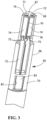
FIG. 3 is a perspective view of the illustrative contact insulator ofFIG. 1 with the contacts not shown. -
FIG. 4 is a perspective view of contacts and cables being brought into engagement with the illustrative contact insulator ofFIG. 1 . -
FIG. 5 is a perspective view of contacts and cables being inserted through a contact receiving opening in the illustrative contact insulator ofFIG. 1 . -
FIG. 6 is a perspective view of four contact insulators attached to four differential pairs of contacts. -
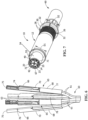
FIG. 7 is a front, side perspective view of an illustrative high speed connector assembly with the contact insulators ofFIG. 6 positioned therein. - An object of the present invention is to provide segmented contact insulators which cooperate with differential pairs of contacts to properly secure the contacts in the contact insulators and to allow for the contacts to be easily inserted into the contact insulators, thereby decreases assembly time and difficulty.
- An object of the present invention is to provide a method to insert the contacts in the contact insulators which properly secures the contacts in the contact insulators and decreases assembly time and difficulty.
- An object of the present invention is to provide a means for removing the contacts from the contact insulators without damaging the contacts. This allows the contacts to be reorganized as needed for correct signal pair orientation without damaging signal contacts or the contact insulators.
- An embodiment is directed to a contact insulator for use with high speed cable with differential pairs of contacts. The contact insulator has a contact receiving portion with a first closed side, a second closed side and a third open side. A conductor receiving portion has a first closed side, an oppositely facing second open side. A transition portion is positioned between the contact receiving portion and the conductor receiving portion. Two contact receiving slots are provided in the contact receiving portion, the contact receiving slots extend from a mating end of the contact insulator to the transition portion. Two conductor receiving slots are provided in the conductor receiving portion, the conductor receiving slots extend from a conductor receiving end of the contact insulator to the transition portion. The second open side and the conductor receiving slots of the conductor receiving portion open in an opposite direction as the open third side and the contact receiving slots of the contact receiving portion. The transition portion has a contact receiving opening which extends through the contact insulator from the second open side of the conductor receiving portion to the open third side of the contact receiving portion. The contact receiving opening is dimensioned to allow the contacts to be inserted therethrough.
- An embodiment is directed to a contact insulator for use with high speed cable with differential pairs of contacts. The contact insulator includes a contact receiving portion and a conductor receiving portion. The contact receiving portion has contact receiving slots for receiving the contact therein. The contact receiving slots open from a first side of the contact insulator. The conductor receiving portion has conductor receiving slots for receiving the signal conductors therein. The conductor receiving slots open from a second side of the contact insulator. A transition portion is positioned between the contact receiving portion and the conductor receiving portion. The transition portion has a contact receiving opening which extends through the contact insulator. The contact receiving opening is dimensioned to allow the contacts to be inserted therethrough. The contact insulator is rotated about the contacts and the signal conductors to position the contacts in the contact receiving slots through the first side of the contact insulator and position the signal conductor in the conductor receiving slots through the second side of the contact insulator.
- An embodiment is directed to a method of terminating a differential pair of contacts to a contact insulator, the contact insulator having a contact receiving portion with contact receiving slots extending from a front of the contact insulator, a conductor receiving portion with conductor receiving slots extending from a rear of the contact insulator, and a transition portion with a contact receiving opening, the contact receiving slots opening in a opposite direction from the conductor receiving slots. The method includes: positioning contacts attached to signal conductors proximate the conductor receiving slots at the rear of the contact insulator; inserting the contact through the contact receiving opening; rotating the contact insulator relative to the contacts and the signal conductor; and positioning the contacts in the contact receiving slots and positioning the signal conductors in the conductor receiving slots.
- As shown in
FIG. 7 , anelectrical connector assembly 10 has ashell housing 12 and acrosstalk shield 14. Theconnector assembly 10 may be a plug connector assembly or a receptacle connector assembly. - The
shell housing 12 has amating end 20 and aconductor receiving end 22. In the illustrative embodiment shown, theshell housing 12 has amating portion 24 proximate themating end 20. Themating portion 24 has a smaller outside diameter D1 than the remainder of theshell housing 12. Themating portion 24 has a contact receiving opening 23 with an inner orinside wall 25 which extends circumferentially around the opening 23. However, other configurations of theshell housing 12 may be used. - A
recessed portion 26 is provided on theshell housing 12 proximate theconductor receiving end 22. Therecessed portion 26 hasmultiple projections 28 which extend from the surface thereof. Therecessed portion 26 has an outer diameter of D2, which is larger than the outside diameter D1 of themating portion 24. Ashoulder 30 extends circumferentially around theconductor receiving end 22 of theshell housing 12. Theshoulder 30 is provided at one end of therecessed portion 26. However, other configurations of theshell housing 12 may be used. - Crosstalk shield receiving recesses or
slots 32 extend from theconductor receiving end 22 toward themating end 20. The crosstalkshield receiving slots 32 extend through theshoulder 30 and into the recessedportion 26. In the embodiment shown, four crosstalkshield receiving slots 32 are provided to accommodate the configuration of thecrosstalk shield 14. However, other numbers of crosstalkshield receiving slots 32 may be used to accommodate different configurations of thecrosstalk shield 14. - The
crosstalk shield 14 has afirst shield member 40 and asecond shield member 42. In the illustrative embodiment, thefirst shield member 40 and thesecond shield member 42 are made from nickel silver material, however, other materials, including corrosion resistant materials, may be used which exhibit the shielding characteristics required. - The
connector assembly 10, including theshell housing 12 and thecrosstalk shield 14 are illustrative. Other types and configurations of theconnector assembly 10 may be used. - A
high speed cable 60 with differential pairs ofsignal conductors 61 is terminated to theshield housing 12 of theconnector assembly 10. Thesignal conductors 61 havecontacts 63 terminated thereto. In the illustrative embodiment shown, four pairs, or eightcontacts 63 are shown. Each of the differential pairs ofcontacts 63 are positioned in respective contact spacers orinsulators 65 and the contact spacers orinsulators 65 are positioned in thecontact receiving cavities 53 defined by thefirst shield member 40 and thesecond shield member 42 of thecrosstalk shield 14. As each of thecontact insulators 65 accommodates only a portion of the total number ofcontacts 63 andsignal conductors 61, thecontact insulators 65 are segmented or modular in nature, as more than onecontact insulator 65 is needed to fully isolate thecontacts 63 andsignal conductors 61. - Each
contact insulator 65 has acontact receiving portion 66 and aconductor receiving portion 68. Atransition portion 70 is positioned between thecontact receiving portion 66 and theconductor receiving portion 68. - The
contact receiving portion 66 has a generally triangular configuration with a first closed wall orside 71, a second closed wall orside 72 and a thirdopen side 73. When assembled, the firstclosed side 71 and the secondclosed side 72 are positioned proximate thefirst shield member 40 and thesecond shield member 42. The openthird side 73 is positioned proximate theinside wall 25 of themating portion 24. The openthird side 73 is necessitated to allow thecontacts 63 to be properly inserted into thecontact insulator 65. - In the illustrative embodiment shown, a
mating wall 67 extends at amating end 75 of thecontact receiving portion 66. Themating wall 67 extends between the first closed wall orside 71, the second closed wall orside 72 and the thirdopen side 73. Matingcontact receiving openings 69 extend through themating wall 67. In other embodiments, themating wall 67 may have a different configuration or may not be present. - As shown in
FIG. 3 , twocontact receiving slots 74 are provided in thecontact receiving portion 66 of eachcontact insulator 65. Thecontact receiving slots 74 extend from themating end 75 of thecontact insulator 65 to thetransition portion 70. Thecontact receiving slots 74 open to the first side or front of thecontact insulator 65 or the thirdopen side 73. Thecontact receiving slots 74 are spaced from each other by aninsulative wall 91 and extend essentially parallel to each other.Retention projections 75 extend into each of thecontact receiving slots 74. - An access opening 76 is provided in each of the
contact receiving slots 74 in thecontact receiving portion 66. The openings extend through one or both of the firstclosed side 71 or the secondclosed side 72 and extend into thecontact receiving slots 74. Theaccess openings 76 are in line with theretention projections 75. Theaccess openings 76 are dimensioned to receive a removal tool (not shown) therein to facilitate the removal of thecontacts 63 from thecontact receiving slots 74 when desired. - The
conductor receiving portion 68 has a first closed wall orside 77, an oppositely facing secondopen side 78. Twoconductor receiving slots 79 are provided in theconductor receiving portion 68 of eachcontact insulator 65. Theconductor receiving slots 79 extend from aconductor receiving end 80 of thecontact insulator 65 to thetransition portion 70. Theconductor receiving slots 79 open to the second side or rear of thecontact insulator 65 or the secondopen side 78. Theconductor receiving slots 79 are spaced from each other by aninsulative wall 81 and extend essentially parallel to each other. - The second
open side 78 and theconductor receiving slots 79 of theconductor receiving portion 68 open in an opposite direction as or to the openthird side 73 and thecontact receiving slots 74 of thecontact receiving portion 66. - The
transition portion 70 has a contact receiving cavity or opening 82 which extends through thecontact insulator 65 from the secondopen side 78 of theconductor receiving portion 68 to the openthird side 73 of thecontact receiving portion 66. Thecontact receiving opening 82 is dimensioned to allow twocontacts 63 to be inserted therethrough. - A
retention latch 83 is provided on thetransition portion 70. Theretention latch 83 extends into thecontact receiving opening 82 but does not prevent the insertion of thecontact 63 through thecontact receiving opening 82. - When assembling the
contacts 63 to thecontact insulator 65, thecontacts 63 are first terminated to thesignal conductors 61. Thecontacts 63 can be terminated to thesignal conductors 61 using known methods of termination. - With the
contacts 63 properly terminated to thesignal conductors 61, a pair ofcontacts 63 are moved into the position proximate the rear of thecontact insulator 65 proximate the secondopen side 78 of theconductor receiving slots 79 of theconductor receiving portion 68, as shown inFIG. 4 . Thecontacts 63 are then inserted through the contact receiving cavity or opening 82 in the direction ofarrow 84. Although the twocontacts 63 are shown being inserted at the same time, eachcontact 63 may be inserted individually. - With the
contacts 63 properly inserted through thecontact receiving opening 82, thecontact insulator 65 is rotated in the direction of thearrows FIG. 5 . In alternative embodiments, thecontacts 63 andsignal conductors 61 may be rotate relative to thecontact insulator 65. - As the rotation of the occurs, the
contacts 63 are moved into thecontact receiving slots 74 of theconductor receiving portion 68. Rotation continues until thecontacts 63 are fully seated in thecontact receiving slots 74, as shown inFIG 1 . In this position, theretention projections 75 in each of thecontact receiving slots 74 frictionally engages thecontacts 63 to physically retain thecontacts 63 in thecontact receiving slots 74. As rotation occurs, thesignal conductors 61 are also moved into position in in theconductor receiving slots 79 of theconductor receiving portion 68. - In the fully inserted position, the
contacts 63 are positioned in thecontact receiving slots 74 through the openthird side 73 of thecontact receiving portion 66. Also in the fully inserted position, thesignal conductors 61 are positioned in theconductor receiving slots 79 through the secondopen side 78 of theconductor receiving slots 79. As the openthird side 73 and the secondopen side 78 open in opposite directions, the positioning of thecontacts 63 and thesignal conductors 61 in both thecontact receiving slots 74 and theconductor receiving slots 79 prevents thecontacts 63 andsignal conductors 61 from being removed without undergoing a rotating or pivoting motion. This adds to the stability of the positioning of thecontacts 63 in thecontact receiving slots 74 and thesignal conductors 61 in theconductor receiving slots 79. - In the illustrative embodiment shown, each
contact insulator 65 is configured to house twocontacts 63. As eightsignal contacts 63 are shown (FIG.6 ), with four differential pairs ofcontacts 63, fourcontact insulators 65 are used to terminate the cable. The same process is used to terminate each of the differential pairs ofcontacts 63. - For each
contact insulator 65, thecontacts 63 are inserted through the rear of thecontact insulator 65 to provide a way to easily manage the installation steps. Thesignal conductors 61 are not able to move to the outer edges of thecontact insulators 65, making it easier to gather thesignal conductors 61 together during installation into the shell. - Once all the
contacts 63 are properly inserted intocontact insulators 65, thecontact insulators 65 are inserted into respectivecontact receiving cavities 53 defined by thefirst shield member 40 and thesecond shield member 42 of thecrosstalk shield 14. The retention latches 83 cooperate with theshell housing 12 to retain thecontact insulators 65 in theshell housing 12 of theconnector assembly 10. - Occasionally,
contacts 63 will need to be removed from thecontact insulator 65 after they are fully seated. When acontact 63 is to be removed from thecontact receiving slot 74, a small diameter tool (not shown) is inserted into theaccess opening 76. The tool can be used to push thecontact 63 past theretention projections 75 in thecontact receiving slot 74, thereby releasing thecontact 63 from thecontact receiving slot 74. As the access opening 76 is located directly in line and behind theretention projections 75 there is no moment applied to thecontact 63 by the tool and thecontact 63 can be pushed directly past theretention projections 75 with no damage to thecontacts 63 or theretention projections 75. In addition, as thecontact insulators 65 housing only pairs ofcontact 63, thecontacts 63 can be more selectively repaired without disturbing the other pairs already seated. - The
contact insulators 65 of the present invention facilitates the controlled manipulation of thesignal conductors 61, asmany signal conductors 61, such as, but not limited to, Cat6a conductor are inherently twisted and tend to move wherever they want while assembly occurs. Creating a way to manage thesignal conductors 61 with features in thecontact insulators 65 decreases assembly time and difficulty. With thesignal conductors 61 andcontacts 63 on opposite sides of thecontact insulator 65, simple relative movements are not able to dislodge thecontacts 63. - Securing the
contacts 63 into theirown contact insulators 65 two-at-a-time allows for the installation of a pair ofcontacts 63 and repeat the same steps on the remaining pairs. The assembledcontact insulators 65 are able to move freely without affecting the other contacts, thereby reducing the complexity and time for assembly. - In addition, the use of the access opening 76 allows for the reorganization of the
contacts 63 for correct signal pair orientation without damaging thecontacts 63 or thecontact insulators 65. This facilitates an easier and more simplified installation process.
Claims (12)
- A contact insulator (65) for use with high speed cable (60) with differential pairs of contacts (63), the contact insulator (65) comprising:a contact receiving portion (66) having a first closed side (71), a second closed side (72) and a third open side (73);a conductor receiving portion (68) having a first closed side (77), an oppositely facing second open side (78);a transition portion (70) positioned between the contact receiving portion (66) and the conductor receiving portion (68);two contact receiving slots (74) provided in the contact receiving portion (66), the contact receiving slots (74) extending from a mating end (75) of the contact insulator (65) to the transition portion (70);two conductor receiving slots (79) provided in the conductor receiving portion (68), the conductor receiving slots (79) extending from a conductor receiving end (80) of the contact insulator (65) to the transition portion (70);the second open side (78) and the conductor receiving slots (79) of the conductor receiving portion (68) opening in an opposite direction to the third open side (73) and the contact receiving slots (74) of the contact receiving portion (66) ;the transition portion (70) having a contact receiving opening (82) which extends through the contact insulator (65) from the second open side (78) of the conductor receiving portion (68) to the third open side (73) of the contact receiving portion (66), the contact receiving opening (82) is dimensioned to allow the contacts (63) to be inserted therethrough.
- The contact insulator (65) as recited in claim 1, wherein retention projections (75) extend into each of the contact receiving slots (74).
- The contact insulator (65) as recited in claim 2, wherein access openings (76) extend through one or both of the first closed side (71) or the second closed side (72) and extend into the contact receiving slots (74), the access openings (76) are dimensioned to receive a removal tool therein to facilitate the removal of contacts (63) positioned in the contact receiving slots (74).
- The contact insulator (65) as recited in claim 3, wherein the access openings (76) are in line with the retention projections (75).
- The contact insulator (65) as recited in any preceding claim, wherein the contact receiving slots (74) are spaced from each other by an insulative wall (91) and extend essentially parallel to each other.
- The contact insulator (65) as recited in any preceding claim, wherein the conductor receiving slots (79) are spaced from each other by an insulative wall (81) and extend essentially parallel to each other.
- The contact insulator (65) as recited in any preceding claim, wherein the contact receiving portion (66) has a generally triangular configuration.
- The contact insulator (65) as recited in any preceding claim, wherein a mating wall (67) extends at the mating end (75) of the contact receiving portion (66), the mating wall (67) extends between first closed side (71), the second closed side (72) and the third open side (73).
- The contact insulator (65) as recited in claim 8, wherein mating contact receiving openings (69) extend through the mating wall (67).
- The contact insulator (65) as recited in any preceding claim, wherein a retention latch (83) is provided on the transition portion (70).
- The contact insulator (65) as recited in claim 10, wherein the retention latch (83) extends into the contact receiving opening (82) but does not prevent the insertion of the contacts (63) through the contact receiving opening (82).
- The contact insulator (65) as recited in any preceding claim in combination with a pair of said contacts (63).
Applications Claiming Priority (1)
| Application Number | Priority Date | Filing Date | Title |
|---|---|---|---|
| US17/732,643 US12266880B2 (en) | 2022-04-29 | 2022-04-29 | Contact insulators for use with differential pairs of contacts and method of termination |
Publications (2)
| Publication Number | Publication Date |
|---|---|
| EP4270676A1 true EP4270676A1 (en) | 2023-11-01 |
| EP4270676B1 EP4270676B1 (en) | 2026-02-25 |
Family
ID=86282488
Family Applications (1)
| Application Number | Title | Priority Date | Filing Date |
|---|---|---|---|
| EP23170514.6A Active EP4270676B1 (en) | 2022-04-29 | 2023-04-27 | Contact insulators for use with differential pairs of contacts |
Country Status (3)
| Country | Link |
|---|---|
| US (1) | US12266880B2 (en) |
| EP (1) | EP4270676B1 (en) |
| CA (1) | CA3198201A1 (en) |
Families Citing this family (4)
| Publication number | Priority date | Publication date | Assignee | Title |
|---|---|---|---|---|
| US12199385B2 (en) | 2022-04-29 | 2025-01-14 | Te Connectivity Solutions Gmbh | High speed cable braid termination using a coil spring |
| US12244105B2 (en) | 2022-04-29 | 2025-03-04 | Te Connectivity Solutions Gmbh | Isolation component for a tightly packaged high speed connector |
| US12244104B2 (en) | 2022-04-29 | 2025-03-04 | Te Connectivity Solutions Gmbh | High speed electrical connector with preassembled EMI shielding |
| DE102024123345A1 (en) * | 2024-08-15 | 2026-02-19 | Harting Electric Stiftung & Co. Kg | Connector module for high-frequency data transmission |
Citations (3)
| Publication number | Priority date | Publication date | Assignee | Title |
|---|---|---|---|---|
| US20120034809A1 (en) * | 2009-04-09 | 2012-02-09 | Phoenix Contact Gmbh & Co. Kg | Electrical plug-in connector and electrical plug-in connection |
| DE202015103479U1 (en) * | 2015-06-11 | 2015-08-03 | Provertha Connectors, Cables & Solutions Gmbh | Circular connector for data transmission of high data rates |
| DE102019106980B3 (en) * | 2019-03-19 | 2020-07-02 | Harting Electric Gmbh & Co. Kg | Contact carriers and connectors for a shielded hybrid contact arrangement |
Family Cites Families (9)
| Publication number | Priority date | Publication date | Assignee | Title |
|---|---|---|---|---|
| DE202012008970U1 (en) | 2012-09-18 | 2012-10-17 | Rosenberger Hochfrequenztechnik Gmbh & Co. Kg | Connectors |
| DE202015100245U1 (en) | 2015-01-21 | 2016-02-02 | FILTEC GmbH Filtertechnologie für die Elektronikindustrie | Socket assembly comprising a shielded socket for printed circuit boards or boards |
| US9257796B1 (en) | 2015-02-09 | 2016-02-09 | Glenair, Inc. | Electrical connector for high-speed transmission using twisted-pair cable |
| US9923285B2 (en) | 2016-06-20 | 2018-03-20 | Richards Manufacturing Company, A New Jersey Limited Partnership | Method and related device for connecting to a metallic shield of a cable |
| US10916893B2 (en) | 2019-06-25 | 2021-02-09 | Itt Manufacturing Enterprises Llc | Crosstalk shield |
| WO2021009833A1 (en) | 2019-07-16 | 2021-01-21 | 三菱電機株式会社 | Connector |
| US12199385B2 (en) | 2022-04-29 | 2025-01-14 | Te Connectivity Solutions Gmbh | High speed cable braid termination using a coil spring |
| US12244105B2 (en) | 2022-04-29 | 2025-03-04 | Te Connectivity Solutions Gmbh | Isolation component for a tightly packaged high speed connector |
| US12244104B2 (en) | 2022-04-29 | 2025-03-04 | Te Connectivity Solutions Gmbh | High speed electrical connector with preassembled EMI shielding |
-
2022
- 2022-04-29 US US17/732,643 patent/US12266880B2/en active Active
-
2023
- 2023-04-27 EP EP23170514.6A patent/EP4270676B1/en active Active
- 2023-04-28 CA CA3198201A patent/CA3198201A1/en active Pending
Patent Citations (3)
| Publication number | Priority date | Publication date | Assignee | Title |
|---|---|---|---|---|
| US20120034809A1 (en) * | 2009-04-09 | 2012-02-09 | Phoenix Contact Gmbh & Co. Kg | Electrical plug-in connector and electrical plug-in connection |
| DE202015103479U1 (en) * | 2015-06-11 | 2015-08-03 | Provertha Connectors, Cables & Solutions Gmbh | Circular connector for data transmission of high data rates |
| DE102019106980B3 (en) * | 2019-03-19 | 2020-07-02 | Harting Electric Gmbh & Co. Kg | Contact carriers and connectors for a shielded hybrid contact arrangement |
Also Published As
| Publication number | Publication date |
|---|---|
| EP4270676B1 (en) | 2026-02-25 |
| US12266880B2 (en) | 2025-04-01 |
| US20230352868A1 (en) | 2023-11-02 |
| CA3198201A1 (en) | 2023-10-29 |
Similar Documents
| Publication | Publication Date | Title |
|---|---|---|
| EP4270676B1 (en) | Contact insulators for use with differential pairs of contacts | |
| US12149032B2 (en) | Connector assembly with grounding | |
| US10476197B2 (en) | Coupler connector and cable terminator with side contacts | |
| US9899760B2 (en) | Electrical connector having a metallic ferrule accommodated within a receptacle and crimped to a cable | |
| EP1014498A2 (en) | Communication cable terminating plug | |
| US10651608B2 (en) | Connector assembly with grounding clamp system | |
| US5421735A (en) | Modular coaxial cable connector | |
| CN113841302B (en) | Contact carrier for shielding a hybrid contact assembly and plug connector | |
| US9583885B2 (en) | Connector assembly with grounding spring | |
| US20140315420A1 (en) | Plug for a data and/or telecommunication cable comprising several conductors | |
| WO1988007775A1 (en) | Terminal stabilization and retention system for an electrical connector | |
| EP2854229A1 (en) | Connector | |
| US5718604A (en) | Patch cord connection system | |
| JPH03134977A (en) | Connector shell assembly body | |
| GB2349516A (en) | Contact-retaining shroud for electrical connector | |
| CN113169492B (en) | Modular telecommunications plugs and methods | |
| JPH0477430B2 (en) | ||
| US20230246404A1 (en) | Single pair ethernet (spe) connector and system | |
| JPH0690510A (en) | Distribution unit and electric connector | |
| GB2229584A (en) | Mounting contacts in an electrical connector | |
| HK36797A (en) | Modular coaxial cable connector |
Legal Events
| Date | Code | Title | Description |
|---|---|---|---|
| PUAI | Public reference made under article 153(3) epc to a published international application that has entered the european phase |
Free format text: ORIGINAL CODE: 0009012 |
|
| STAA | Information on the status of an ep patent application or granted ep patent |
Free format text: STATUS: THE APPLICATION HAS BEEN PUBLISHED |
|
| AK | Designated contracting states |
Kind code of ref document: A1 Designated state(s): AL AT BE BG CH CY CZ DE DK EE ES FI FR GB GR HR HU IE IS IT LI LT LU LV MC ME MK MT NL NO PL PT RO RS SE SI SK SM TR |
|
| STAA | Information on the status of an ep patent application or granted ep patent |
Free format text: STATUS: REQUEST FOR EXAMINATION WAS MADE |
|
| 17P | Request for examination filed |
Effective date: 20240501 |
|
| RBV | Designated contracting states (corrected) |
Designated state(s): AL AT BE BG CH CY CZ DE DK EE ES FI FR GB GR HR HU IE IS IT LI LT LU LV MC ME MK MT NL NO PL PT RO RS SE SI SK SM TR |
|
| GRAP | Despatch of communication of intention to grant a patent |
Free format text: ORIGINAL CODE: EPIDOSNIGR1 |
|
| STAA | Information on the status of an ep patent application or granted ep patent |
Free format text: STATUS: GRANT OF PATENT IS INTENDED |
|
| INTG | Intention to grant announced |
Effective date: 20251008 |
|
| RIC1 | Information provided on ipc code assigned before grant |
Ipc: H01R 13/518 20060101AFI20250926BHEP Ipc: H01R 13/6463 20110101ALI20250926BHEP Ipc: H01R 13/506 20060101ALN20250926BHEP Ipc: H01R 24/86 20110101ALN20250926BHEP Ipc: H01R 43/20 20060101ALN20250926BHEP |
|
| GRAS | Grant fee paid |
Free format text: ORIGINAL CODE: EPIDOSNIGR3 |
|
| GRAA | (expected) grant |
Free format text: ORIGINAL CODE: 0009210 |
|
| STAA | Information on the status of an ep patent application or granted ep patent |
Free format text: STATUS: THE PATENT HAS BEEN GRANTED |
|
| AK | Designated contracting states |
Kind code of ref document: B1 Designated state(s): AL AT BE BG CH CY CZ DE DK EE ES FI FR GB GR HR HU IE IS IT LI LT LU LV MC ME MK MT NL NO PL PT RO RS SE SI SK SM TR |
|
| REG | Reference to a national code |
Ref country code: CH Ref legal event code: F10 Free format text: ST27 STATUS EVENT CODE: U-0-0-F10-F00 (AS PROVIDED BY THE NATIONAL OFFICE) Effective date: 20260225 Ref country code: GB Ref legal event code: FG4D |
|
| REG | Reference to a national code |
Ref country code: DE Ref legal event code: R096 Ref document number: 602023012433 Country of ref document: DE |
|
| REG | Reference to a national code |
Ref country code: IE Ref legal event code: FG4D |
|
| PGFP | Annual fee paid to national office [announced via postgrant information from national office to epo] |
Ref country code: FR Payment date: 20260309 Year of fee payment: 4 |
|
| REG | Reference to a national code |
Ref country code: NL Ref legal event code: MP Effective date: 20260225 |
|
| PG25 | Lapsed in a contracting state [announced via postgrant information from national office to epo] |
Ref country code: RS Free format text: LAPSE BECAUSE OF FAILURE TO SUBMIT A TRANSLATION OF THE DESCRIPTION OR TO PAY THE FEE WITHIN THE PRESCRIBED TIME-LIMIT Effective date: 20260525 |
|
| PG25 | Lapsed in a contracting state [announced via postgrant information from national office to epo] |
Ref country code: ES Free format text: LAPSE BECAUSE OF FAILURE TO SUBMIT A TRANSLATION OF THE DESCRIPTION OR TO PAY THE FEE WITHIN THE PRESCRIBED TIME-LIMIT Effective date: 20260225 |
|
| PG25 | Lapsed in a contracting state [announced via postgrant information from national office to epo] |
Ref country code: PL Free format text: LAPSE BECAUSE OF FAILURE TO SUBMIT A TRANSLATION OF THE DESCRIPTION OR TO PAY THE FEE WITHIN THE PRESCRIBED TIME-LIMIT Effective date: 20260225 |
|
| PG25 | Lapsed in a contracting state [announced via postgrant information from national office to epo] |
Ref country code: GR Free format text: LAPSE BECAUSE OF FAILURE TO SUBMIT A TRANSLATION OF THE DESCRIPTION OR TO PAY THE FEE WITHIN THE PRESCRIBED TIME-LIMIT Effective date: 20260526 |
|
| REG | Reference to a national code |
Ref country code: LT Ref legal event code: MG9D |
|
| PG25 | Lapsed in a contracting state [announced via postgrant information from national office to epo] |
Ref country code: LT Free format text: LAPSE BECAUSE OF FAILURE TO SUBMIT A TRANSLATION OF THE DESCRIPTION OR TO PAY THE FEE WITHIN THE PRESCRIBED TIME-LIMIT Effective date: 20260225 |
|
| PGFP | Annual fee paid to national office [announced via postgrant information from national office to epo] |
Ref country code: DE Payment date: 20260305 Year of fee payment: 4 |
|
| PG25 | Lapsed in a contracting state [announced via postgrant information from national office to epo] |
Ref country code: NO Free format text: LAPSE BECAUSE OF FAILURE TO SUBMIT A TRANSLATION OF THE DESCRIPTION OR TO PAY THE FEE WITHIN THE PRESCRIBED TIME-LIMIT Effective date: 20260525 |
|
| PG25 | Lapsed in a contracting state [announced via postgrant information from national office to epo] |
Ref country code: FI Free format text: LAPSE BECAUSE OF FAILURE TO SUBMIT A TRANSLATION OF THE DESCRIPTION OR TO PAY THE FEE WITHIN THE PRESCRIBED TIME-LIMIT Effective date: 20260225 Ref country code: SE Free format text: LAPSE BECAUSE OF FAILURE TO SUBMIT A TRANSLATION OF THE DESCRIPTION OR TO PAY THE FEE WITHIN THE PRESCRIBED TIME-LIMIT Effective date: 20260225 Ref country code: AT Free format text: LAPSE BECAUSE OF FAILURE TO SUBMIT A TRANSLATION OF THE DESCRIPTION OR TO PAY THE FEE WITHIN THE PRESCRIBED TIME-LIMIT Effective date: 20260225 |
|
| REG | Reference to a national code |
Ref country code: AT Ref legal event code: MK05 Ref document number: 1892078 Country of ref document: AT Kind code of ref document: T Effective date: 20260225 |
|
| PG25 | Lapsed in a contracting state [announced via postgrant information from national office to epo] |
Ref country code: HR Free format text: LAPSE BECAUSE OF FAILURE TO SUBMIT A TRANSLATION OF THE DESCRIPTION OR TO PAY THE FEE WITHIN THE PRESCRIBED TIME-LIMIT Effective date: 20260225 |
|
| PG25 | Lapsed in a contracting state [announced via postgrant information from national office to epo] |
Ref country code: PT Free format text: LAPSE BECAUSE OF FAILURE TO SUBMIT A TRANSLATION OF THE DESCRIPTION OR TO PAY THE FEE WITHIN THE PRESCRIBED TIME-LIMIT Effective date: 20260625 Ref country code: IS Free format text: LAPSE BECAUSE OF FAILURE TO SUBMIT A TRANSLATION OF THE DESCRIPTION OR TO PAY THE FEE WITHIN THE PRESCRIBED TIME-LIMIT Effective date: 20260625 |
|
| PG25 | Lapsed in a contracting state [announced via postgrant information from national office to epo] |
Ref country code: NL Free format text: LAPSE BECAUSE OF FAILURE TO SUBMIT A TRANSLATION OF THE DESCRIPTION OR TO PAY THE FEE WITHIN THE PRESCRIBED TIME-LIMIT Effective date: 20260225 |
|
| PG25 | Lapsed in a contracting state [announced via postgrant information from national office to epo] |
Ref country code: LV Free format text: LAPSE BECAUSE OF FAILURE TO SUBMIT A TRANSLATION OF THE DESCRIPTION OR TO PAY THE FEE WITHIN THE PRESCRIBED TIME-LIMIT Effective date: 20260225 |
|
| PG25 | Lapsed in a contracting state [announced via postgrant information from national office to epo] |
Ref country code: BG Free format text: LAPSE BECAUSE OF FAILURE TO SUBMIT A TRANSLATION OF THE DESCRIPTION OR TO PAY THE FEE WITHIN THE PRESCRIBED TIME-LIMIT Effective date: 20260225 |