EP4270631A1 - Battery cell assembly comprising bus bar to which flame blocking member is added and battery cell assembly structure comprising same - Google Patents
Battery cell assembly comprising bus bar to which flame blocking member is added and battery cell assembly structure comprising same Download PDFInfo
- Publication number
- EP4270631A1 EP4270631A1 EP22919056.6A EP22919056A EP4270631A1 EP 4270631 A1 EP4270631 A1 EP 4270631A1 EP 22919056 A EP22919056 A EP 22919056A EP 4270631 A1 EP4270631 A1 EP 4270631A1
- Authority
- EP
- European Patent Office
- Prior art keywords
- battery cell
- bus bar
- cover
- cell assembly
- pouch
- Prior art date
- Legal status (The legal status is an assumption and is not a legal conclusion. Google has not performed a legal analysis and makes no representation as to the accuracy of the status listed.)
- Granted
Links
Images





Classifications
-
- H—ELECTRICITY
- H01—ELECTRIC ELEMENTS
- H01M—PROCESSES OR MEANS, e.g. BATTERIES, FOR THE DIRECT CONVERSION OF CHEMICAL ENERGY INTO ELECTRICAL ENERGY
- H01M10/00—Secondary cells; Manufacture thereof
- H01M10/42—Methods or arrangements for servicing or maintenance of secondary cells or secondary half-cells
- H01M10/4235—Safety or regulating additives or arrangements in electrodes, separators or electrolyte
-
- H—ELECTRICITY
- H01—ELECTRIC ELEMENTS
- H01M—PROCESSES OR MEANS, e.g. BATTERIES, FOR THE DIRECT CONVERSION OF CHEMICAL ENERGY INTO ELECTRICAL ENERGY
- H01M50/00—Constructional details or processes of manufacture of the non-active parts of electrochemical cells other than fuel cells, e.g. hybrid cells
- H01M50/50—Current conducting connections for cells or batteries
- H01M50/572—Means for preventing undesired use or discharge
- H01M50/584—Means for preventing undesired use or discharge for preventing incorrect connections inside or outside the batteries
- H01M50/59—Means for preventing undesired use or discharge for preventing incorrect connections inside or outside the batteries characterised by the protection means
- H01M50/591—Covers
-
- H—ELECTRICITY
- H01—ELECTRIC ELEMENTS
- H01M—PROCESSES OR MEANS, e.g. BATTERIES, FOR THE DIRECT CONVERSION OF CHEMICAL ENERGY INTO ELECTRICAL ENERGY
- H01M10/00—Secondary cells; Manufacture thereof
- H01M10/05—Accumulators with non-aqueous electrolyte
- H01M10/052—Li-accumulators
- H01M10/0525—Rocking-chair batteries, i.e. batteries with lithium insertion or intercalation in both electrodes; Lithium-ion batteries
-
- H—ELECTRICITY
- H01—ELECTRIC ELEMENTS
- H01M—PROCESSES OR MEANS, e.g. BATTERIES, FOR THE DIRECT CONVERSION OF CHEMICAL ENERGY INTO ELECTRICAL ENERGY
- H01M10/00—Secondary cells; Manufacture thereof
- H01M10/05—Accumulators with non-aqueous electrolyte
- H01M10/056—Accumulators with non-aqueous electrolyte characterised by the materials used as electrolytes, e.g. mixed inorganic/organic electrolytes
- H01M10/0564—Accumulators with non-aqueous electrolyte characterised by the materials used as electrolytes, e.g. mixed inorganic/organic electrolytes the electrolyte being constituted of organic materials only
- H01M10/0566—Liquid materials
- H01M10/0567—Liquid materials characterised by the additives
-
- H—ELECTRICITY
- H01—ELECTRIC ELEMENTS
- H01M—PROCESSES OR MEANS, e.g. BATTERIES, FOR THE DIRECT CONVERSION OF CHEMICAL ENERGY INTO ELECTRICAL ENERGY
- H01M10/00—Secondary cells; Manufacture thereof
- H01M10/05—Accumulators with non-aqueous electrolyte
- H01M10/056—Accumulators with non-aqueous electrolyte characterised by the materials used as electrolytes, e.g. mixed inorganic/organic electrolytes
- H01M10/0564—Accumulators with non-aqueous electrolyte characterised by the materials used as electrolytes, e.g. mixed inorganic/organic electrolytes the electrolyte being constituted of organic materials only
- H01M10/0566—Liquid materials
- H01M10/0569—Liquid materials characterised by the solvents
-
- H—ELECTRICITY
- H01—ELECTRIC ELEMENTS
- H01M—PROCESSES OR MEANS, e.g. BATTERIES, FOR THE DIRECT CONVERSION OF CHEMICAL ENERGY INTO ELECTRICAL ENERGY
- H01M4/00—Electrodes
- H01M4/02—Electrodes composed of, or comprising, active material
- H01M4/36—Selection of substances as active materials, active masses, active liquids
- H01M4/362—Composites
- H01M4/364—Composites as mixtures
-
- H—ELECTRICITY
- H01—ELECTRIC ELEMENTS
- H01M—PROCESSES OR MEANS, e.g. BATTERIES, FOR THE DIRECT CONVERSION OF CHEMICAL ENERGY INTO ELECTRICAL ENERGY
- H01M4/00—Electrodes
- H01M4/02—Electrodes composed of, or comprising, active material
- H01M4/36—Selection of substances as active materials, active masses, active liquids
- H01M4/362—Composites
- H01M4/366—Composites as layered products
-
- H—ELECTRICITY
- H01—ELECTRIC ELEMENTS
- H01M—PROCESSES OR MEANS, e.g. BATTERIES, FOR THE DIRECT CONVERSION OF CHEMICAL ENERGY INTO ELECTRICAL ENERGY
- H01M4/00—Electrodes
- H01M4/02—Electrodes composed of, or comprising, active material
- H01M4/36—Selection of substances as active materials, active masses, active liquids
- H01M4/38—Selection of substances as active materials, active masses, active liquids of elements or alloys
- H01M4/386—Silicon or alloys based on silicon
-
- H—ELECTRICITY
- H01—ELECTRIC ELEMENTS
- H01M—PROCESSES OR MEANS, e.g. BATTERIES, FOR THE DIRECT CONVERSION OF CHEMICAL ENERGY INTO ELECTRICAL ENERGY
- H01M4/00—Electrodes
- H01M4/02—Electrodes composed of, or comprising, active material
- H01M4/36—Selection of substances as active materials, active masses, active liquids
- H01M4/48—Selection of substances as active materials, active masses, active liquids of inorganic oxides or hydroxides
- H01M4/52—Selection of substances as active materials, active masses, active liquids of inorganic oxides or hydroxides of nickel, cobalt or iron
- H01M4/525—Selection of substances as active materials, active masses, active liquids of inorganic oxides or hydroxides of nickel, cobalt or iron of mixed oxides or hydroxides containing iron, cobalt or nickel for inserting or intercalating light metals, e.g. LiNiO2, LiCoO2 or LiCoOxFy
-
- H—ELECTRICITY
- H01—ELECTRIC ELEMENTS
- H01M—PROCESSES OR MEANS, e.g. BATTERIES, FOR THE DIRECT CONVERSION OF CHEMICAL ENERGY INTO ELECTRICAL ENERGY
- H01M4/00—Electrodes
- H01M4/02—Electrodes composed of, or comprising, active material
- H01M4/36—Selection of substances as active materials, active masses, active liquids
- H01M4/58—Selection of substances as active materials, active masses, active liquids of inorganic compounds other than oxides or hydroxides, e.g. sulfides, selenides, tellurides, halogenides or LiCoFy; of polyanionic structures, e.g. phosphates, silicates or borates
- H01M4/583—Carbonaceous material, e.g. graphite-intercalation compounds or CFx
- H01M4/587—Carbonaceous material, e.g. graphite-intercalation compounds or CFx for inserting or intercalating light metals
-
- H—ELECTRICITY
- H01—ELECTRIC ELEMENTS
- H01M—PROCESSES OR MEANS, e.g. BATTERIES, FOR THE DIRECT CONVERSION OF CHEMICAL ENERGY INTO ELECTRICAL ENERGY
- H01M50/00—Constructional details or processes of manufacture of the non-active parts of electrochemical cells other than fuel cells, e.g. hybrid cells
- H01M50/10—Primary casings; Jackets or wrappings
- H01M50/102—Primary casings; Jackets or wrappings characterised by their shape or physical structure
- H01M50/105—Pouches or flexible bags
-
- H—ELECTRICITY
- H01—ELECTRIC ELEMENTS
- H01M—PROCESSES OR MEANS, e.g. BATTERIES, FOR THE DIRECT CONVERSION OF CHEMICAL ENERGY INTO ELECTRICAL ENERGY
- H01M50/00—Constructional details or processes of manufacture of the non-active parts of electrochemical cells other than fuel cells, e.g. hybrid cells
- H01M50/10—Primary casings; Jackets or wrappings
- H01M50/172—Arrangements of electric connectors penetrating the casing
- H01M50/174—Arrangements of electric connectors penetrating the casing adapted for the shape of the cells
- H01M50/178—Arrangements of electric connectors penetrating the casing adapted for the shape of the cells for pouch or flexible bag cells
-
- H—ELECTRICITY
- H01—ELECTRIC ELEMENTS
- H01M—PROCESSES OR MEANS, e.g. BATTERIES, FOR THE DIRECT CONVERSION OF CHEMICAL ENERGY INTO ELECTRICAL ENERGY
- H01M50/00—Constructional details or processes of manufacture of the non-active parts of electrochemical cells other than fuel cells, e.g. hybrid cells
- H01M50/20—Mountings; Secondary casings or frames; Racks, modules or packs; Suspension devices; Shock absorbers; Transport or carrying devices; Holders
- H01M50/204—Racks, modules or packs for multiple batteries or multiple cells
- H01M50/207—Racks, modules or packs for multiple batteries or multiple cells characterised by their shape
- H01M50/211—Racks, modules or packs for multiple batteries or multiple cells characterised by their shape adapted for pouch cells
-
- H—ELECTRICITY
- H01—ELECTRIC ELEMENTS
- H01M—PROCESSES OR MEANS, e.g. BATTERIES, FOR THE DIRECT CONVERSION OF CHEMICAL ENERGY INTO ELECTRICAL ENERGY
- H01M50/00—Constructional details or processes of manufacture of the non-active parts of electrochemical cells other than fuel cells, e.g. hybrid cells
- H01M50/20—Mountings; Secondary casings or frames; Racks, modules or packs; Suspension devices; Shock absorbers; Transport or carrying devices; Holders
- H01M50/249—Mountings; Secondary casings or frames; Racks, modules or packs; Suspension devices; Shock absorbers; Transport or carrying devices; Holders specially adapted for aircraft or vehicles, e.g. cars or trains
-
- H—ELECTRICITY
- H01—ELECTRIC ELEMENTS
- H01M—PROCESSES OR MEANS, e.g. BATTERIES, FOR THE DIRECT CONVERSION OF CHEMICAL ENERGY INTO ELECTRICAL ENERGY
- H01M50/00—Constructional details or processes of manufacture of the non-active parts of electrochemical cells other than fuel cells, e.g. hybrid cells
- H01M50/30—Arrangements for facilitating escape of gases
- H01M50/383—Flame arresting or ignition-preventing means
-
- H—ELECTRICITY
- H01—ELECTRIC ELEMENTS
- H01M—PROCESSES OR MEANS, e.g. BATTERIES, FOR THE DIRECT CONVERSION OF CHEMICAL ENERGY INTO ELECTRICAL ENERGY
- H01M50/00—Constructional details or processes of manufacture of the non-active parts of electrochemical cells other than fuel cells, e.g. hybrid cells
- H01M50/30—Arrangements for facilitating escape of gases
- H01M50/394—Gas-pervious parts or elements
-
- H—ELECTRICITY
- H01—ELECTRIC ELEMENTS
- H01M—PROCESSES OR MEANS, e.g. BATTERIES, FOR THE DIRECT CONVERSION OF CHEMICAL ENERGY INTO ELECTRICAL ENERGY
- H01M50/00—Constructional details or processes of manufacture of the non-active parts of electrochemical cells other than fuel cells, e.g. hybrid cells
- H01M50/50—Current conducting connections for cells or batteries
- H01M50/502—Interconnectors for connecting terminals of adjacent batteries; Interconnectors for connecting cells outside a battery casing
-
- H—ELECTRICITY
- H01—ELECTRIC ELEMENTS
- H01M—PROCESSES OR MEANS, e.g. BATTERIES, FOR THE DIRECT CONVERSION OF CHEMICAL ENERGY INTO ELECTRICAL ENERGY
- H01M50/00—Constructional details or processes of manufacture of the non-active parts of electrochemical cells other than fuel cells, e.g. hybrid cells
- H01M50/50—Current conducting connections for cells or batteries
- H01M50/502—Interconnectors for connecting terminals of adjacent batteries; Interconnectors for connecting cells outside a battery casing
- H01M50/503—Interconnectors for connecting terminals of adjacent batteries; Interconnectors for connecting cells outside a battery casing characterised by the shape of the interconnectors
-
- H—ELECTRICITY
- H01—ELECTRIC ELEMENTS
- H01M—PROCESSES OR MEANS, e.g. BATTERIES, FOR THE DIRECT CONVERSION OF CHEMICAL ENERGY INTO ELECTRICAL ENERGY
- H01M50/00—Constructional details or processes of manufacture of the non-active parts of electrochemical cells other than fuel cells, e.g. hybrid cells
- H01M50/50—Current conducting connections for cells or batteries
- H01M50/502—Interconnectors for connecting terminals of adjacent batteries; Interconnectors for connecting cells outside a battery casing
- H01M50/505—Interconnectors for connecting terminals of adjacent batteries; Interconnectors for connecting cells outside a battery casing comprising a single busbar
-
- H—ELECTRICITY
- H01—ELECTRIC ELEMENTS
- H01M—PROCESSES OR MEANS, e.g. BATTERIES, FOR THE DIRECT CONVERSION OF CHEMICAL ENERGY INTO ELECTRICAL ENERGY
- H01M4/00—Electrodes
- H01M4/02—Electrodes composed of, or comprising, active material
- H01M2004/021—Physical characteristics, e.g. porosity, surface area
-
- H—ELECTRICITY
- H01—ELECTRIC ELEMENTS
- H01M—PROCESSES OR MEANS, e.g. BATTERIES, FOR THE DIRECT CONVERSION OF CHEMICAL ENERGY INTO ELECTRICAL ENERGY
- H01M4/00—Electrodes
- H01M4/02—Electrodes composed of, or comprising, active material
- H01M2004/026—Electrodes composed of, or comprising, active material characterised by the polarity
- H01M2004/027—Negative electrodes
-
- H—ELECTRICITY
- H01—ELECTRIC ELEMENTS
- H01M—PROCESSES OR MEANS, e.g. BATTERIES, FOR THE DIRECT CONVERSION OF CHEMICAL ENERGY INTO ELECTRICAL ENERGY
- H01M4/00—Electrodes
- H01M4/02—Electrodes composed of, or comprising, active material
- H01M2004/026—Electrodes composed of, or comprising, active material characterised by the polarity
- H01M2004/028—Positive electrodes
-
- H—ELECTRICITY
- H01—ELECTRIC ELEMENTS
- H01M—PROCESSES OR MEANS, e.g. BATTERIES, FOR THE DIRECT CONVERSION OF CHEMICAL ENERGY INTO ELECTRICAL ENERGY
- H01M2220/00—Batteries for particular applications
- H01M2220/20—Batteries in motive systems, e.g. vehicle, ship, plane
-
- H—ELECTRICITY
- H01—ELECTRIC ELEMENTS
- H01M—PROCESSES OR MEANS, e.g. BATTERIES, FOR THE DIRECT CONVERSION OF CHEMICAL ENERGY INTO ELECTRICAL ENERGY
- H01M2300/00—Electrolytes
- H01M2300/0017—Non-aqueous electrolytes
- H01M2300/0025—Organic electrolyte
- H01M2300/0028—Organic electrolyte characterised by the solvent
- H01M2300/0037—Mixture of solvents
- H01M2300/0042—Four or more solvents
-
- Y—GENERAL TAGGING OF NEW TECHNOLOGICAL DEVELOPMENTS; GENERAL TAGGING OF CROSS-SECTIONAL TECHNOLOGIES SPANNING OVER SEVERAL SECTIONS OF THE IPC; TECHNICAL SUBJECTS COVERED BY FORMER USPC CROSS-REFERENCE ART COLLECTIONS [XRACs] AND DIGESTS
- Y02—TECHNOLOGIES OR APPLICATIONS FOR MITIGATION OR ADAPTATION AGAINST CLIMATE CHANGE
- Y02E—REDUCTION OF GREENHOUSE GAS [GHG] EMISSIONS, RELATED TO ENERGY GENERATION, TRANSMISSION OR DISTRIBUTION
- Y02E60/00—Enabling technologies; Technologies with a potential or indirect contribution to GHG emissions mitigation
- Y02E60/10—Energy storage using batteries
Definitions
- the present disclosure relates to a battery cell assembly including a bus bar with a flame blocking member and a battery cell assembly structure including the battery cell assembly. More particularly, the present disclosure relates to a battery cell assembly including a bus bar to which a flame blocking member is added to prevent thermal runaway due to ignition of a battery cell from spreading to adjacent battery cells, and a battery cell assembly structure including the battery cell assembly.
- Lithium secondary batteries that may be charged and discharged are used not only as energy sources for small devices such as mobile devices, but also as energy sources for medium and large-sized devices such as electric vehicles and power storage devices with the development of technology for increasing capacity and improving safety.
- lithium secondary batteries are used as high-capacity and high-power energy sources, ensuring the safety of lithium secondary batteries has become an important issue of interest.
- a temperature of the secondary battery is inevitably increased, and the temperature increase of the secondary battery may degrade the performance of a battery cell.
- a lithium secondary battery has a risk of explosion due to overheating, and when a flame caused by the explosion spreads to adjacent battery cells, it is difficult to suppress a fire until they are burned down.
- thermal runaway occurs in a battery cell, a flame, particles, and gas venting above an ignition point may be generated, and the flame, etc. may propagate to adjacent battery cells, which may eventually lead to the explosion of the battery cell.
- Korean Patent Application Publication No. 2020-0059024 (prior art 1) relates to a battery module having an air-cooled structure in which, because a portion where an electrode lead connected to a battery cell and a bus bar meet on a rear surface of a bus bar frame and are welded is surrounded by a thermal insulation pad, the thermal insulation pad may prevent heat caused by gas or flame from propagating to adjacent battery cells.
- the prior art 1 has a problem in that, because the thermal insulation pad is added to cover the portion where the electrode lead and the bus bar are welded, a size of the battery module is increased by a thickness of the thermal insulation pad.
- Korean Patent Application Publication No. 2017-0014309 discloses a pouch-type secondary battery in which a flame prevention net is added to the inside or the outside of an exterior member of the pouch-type secondary battery, a battery module including a flame prevention net inside and/or outside the battery module, and a battery module including a flame prevention net on at least one surface of a sealed box in which an assembly of secondary batteries is accommodated.
- the prior art 2 does not disclose a configuration for blocking propagation of a flame to an electrode lead.
- the present disclosure is designed to solve the problems of the related art, and therefore the present disclosure is directed to providing a battery cell assembly in which a temperature of a flame, high-temperature particles, and gas generated in an ignited battery cell may be lowered and thermal runaway may be prevented from spreading to other adjacent battery cell assemblies, and a battery cell assembly structure including the battery cell assembly.
- a battery cell assembly including at least one pouch-type battery cell, a cell cover surrounding the at least one pouch-type battery cell, a bus bar connected to an electrode lead of the at least one pouch-type battery cell, and a bus bar frame supporting the bus bar and covering a front open end or a rear open end of the cell cover where the electrode lead is located in the cell cover, wherein a flame blocking member including a mesh net formed of a material with high rigidity and high heat resistance is coupled to a body of the bus bar.
- Each of the at least one pouch-type battery cell may be a bidirectional battery cell in which a positive electrode lead and a negative electrode lead protrude in opposite directions from both ends in a full-length direction, wherein the cell cover has a quadrangular frame shape surrounding four outer surfaces excluding a direction in which the positive electrode lead and the negative electrode lead protrude, or an n-like frame shape surrounding three outer surfaces of the four outer surfaces.
- the flame blocking member may be integrally coupled to the bus bar.
- the flame blocking member may be formed so that a plurality of net structures, each including a mesh net formed of a material with high rigidity and high heat resistance, overlap each other.
- the flame blocking member may include a first net structure welded to one surface of the bus bar and located toward an inside of the cell cover with respect to the bus bar, and a second net structure welded to the other surface of the bus bar and located toward an outside of the cell cover with respect to the bus bar.
- the bus bar may include a through-hole in the body, wherein the through-hole is covered by the flame blocking member.
- the flame blocking member may have a net structure in which a plurality of mesh nets are stacked, and may be filled in the through-hole.
- the bus bar may include a terminal portion for electrical connection with another adjacent battery cell assembly, wherein the terminal portion is a portion of the bus bar extending upward beyond the flame blocking member.
- the bus bar may include a terminal portion for electrical connection with another adjacent battery cell assembly, wherein the terminal portion is located on the cell cover.
- the bus bar and the bus bar frame may include a first surface erected and located at the front open end or the rear open end of the cell cover, and a second surface bent from the first surface and located on the cell cover, wherein the terminal portion is provided on the second surface.
- the flame blocking member may be formed of a copper or stainless steel material.
- the at least one pouch-type battery cell may be accommodated in a state where a receiving portion (a portion where an electrode assembly is received) is erected perpendicular to a ground, wherein the cell cover includes an upper cover portion surrounding an upper edge portion of the at least one pouch-type battery cell, a first side cover portion surrounding a side surface of the receiving portion of the at least one pouch-type battery cell, and a second side cover portion surrounding the other surface of the receiving portion of the at least one pouch-type battery cell.
- the cover portion of the cell cover may include at least one venting hole through which gas is discharged.
- a flame arrestor including one or more mesh nets may be coupled to the at least one venting hole.
- the cell cover may include a cut-out portion formed by cutting each of upper corner portions of both ends of the cell cover in a full-length direction, wherein the bus bar includes a terminal portion exposed to an upper portion of the cell cover through the cut-out portion and functioning as a positive electrode terminal or a negative electrode terminal of the battery cell assembly.
- a battery cell assembly structure including a base plate on which battery cell assemblies are mounted, a support member located on side surfaces of the battery cell assemblies in a full-length direction, and a fixing member added to fix positions of the battery cell assemblies and coupled to the support member.
- a battery pack including the battery cell assembly.
- an electric vehicle including the battery cell assembly.
- a flame or high-temperature particles generated due to ignition of a battery cell may be prevented from being indiscriminately discharged in a full-length direction of a battery cell assembly where a bus bar is located.
- a flame, high-temperature particles, and high-temperature gas ejected from a battery cell may be cooled while passing through a flame blocking member, and some may be blocked from being discharged, the risk of external ignition or propagation of heat sources may be reduced.
- the pouch-type battery cell may be protected from external impact and may be prevented from being damaged or broken during a handing process.
- a discharge direction of gas or flame ejected from the pouch-type battery cell may be controlled to be an upward or downward direction. Accordingly, propagation of thermal runaway between adjacent battery cell assemblies may be effectively prevented.
- the present disclosure may have various other effects, which will be described in each embodiment, or descriptions of effects that may be easily inferred by one of ordinary skill in the art will be omitted.
- FIG. 1 is a perspective view illustrating a battery cell assembly, according to a first embodiment.
- a battery cell assembly 100 includes at least one pouch-type battery cell 110, a cell cover 120 at least partially surrounding the pouch-type battery cell 110, a bus bar 130 connected to an electrode lead of the pouch-type battery cell 110, and a bus bar frame 140 supporting the bus bar 130 and covering a front open end or a rear open end of the cell cover 120 where the electrode lead 111 is located in the cell cover 111, and a flame blocking member 150 including a mesh net formed of a material with high rigidity/high heat resistance may be coupled to a body of the bus bar 130.
- the pouch-type battery cell 110 is long in a full-length direction L, and is a bidirectional battery cell in which a positive electrode lead and a negative electrode lead protrude in opposite directions from both ends in the full-length direction L.
- the bus bar frame 140, the bus bar 130, and the flame blocking member 150 are provided at each of both ends in the full-length direction L where the electrode lead 111 extends.
- the bus bar frame 140 may be formed of an insulating material, and may be coupled to both ends of the cell cover 120 in the full-length direction to cover an open end of the cell cover 120.
- the bus bar 130 is formed of a metal material having electrical conductivity, and is attached to an outer surface of the bus bar frame 140.
- a slit 143 through which an electrode lead 111 may pass may be formed in the bus bar frame 140, and the electrode lead 111 may pass through the slit 143, may be withdrawn out of the bus bar frame 140, may be bent to face the bus bar 130, and may be fixedly coupled to the bus bar 130 by using welding or the like.
- a through-hole may be formed in the bus bar 130, and the flame blocking member 150 may be mounted on the bus bar 130 to completely cover the through-hole.
- the number and shape of battery cells illustrated in FIG. 1 are merely examples, and a size and shape of the bus bar 130 may vary according to the number of battery cells 110 coupled to the bus bar 130 and a series/parallel connection state of the battery cells 110.
- the flame blocking member 150 may be integrally coupled to the bus bar 130 by using welding or the like.
- the flame blocking member 150 may include one net structure, or may include a plurality of net structures, for example, two, or three or more net structures, which overlap each other.
- the flame blocking member 150 may be indirectly mounted on the bus bar 130.
- the flame blocking member 150 may be located outside the bus bar frame 140 to which the bus bar 130 is coupled, and the flame blocking member 150 may include one, or two or more net structures.
- a fixing plate located between the net structures to fix positions of the net structures to be spaced apart from each other, and a case in which the net structures and the fixing plate are accommodated may be provided.
- an insulating cover for insulation between the case and the electrode lead 111 coupled to the bus bar may be located between the bus bar frame 140 and the case.
- the flame blocking member 150 including a net structure may be accommodated in the case, and the case may be coupled to the bus bar frame 140 to which the bus bar 130 is coupled. As such, when the flame blocking member 150 is accommodated in a separate case and then is coupled to the bus bar frame, the flame blocking member 150 may be directly mounted on the bus bar 130.
- the flame blocking member 150 includes a plurality of net structures that overlap each other, a flame, particles, and gas generated due to ignition of the battery cell 110 may be cooled while passing through the plurality of net structures. Also, the flame or particles may be filtered by the net structures and may be prevented from being discharged to the outside.
- particulate byproducts generated during ignition of the battery cell 110 are ejected as particles.
- particulate byproducts may be filtered, and thus, the particles may be prevented from being discharged to the outside.
- the flame blocking member 150 may prevent a flame, particles, or gas generated outside the battery cell 110 from spreading to the battery cell 110.
- the flame blocking member 150 may be formed of a material with high rigidity and high heat resistance to block a flame, sparks, and gas, for example, copper or stainless steel.
- FIG. 2 is a front view illustrating the battery cells 110 to which the cell cover 120 is added, according to the present disclosure.
- the cell cover 120 shown in (a) has a quadrangular frame shape surrounding four outer surfaces excluding a direction in which the electrode lead 111 protrudes, and the cell cover 120 shown in (b) has an n-like frame shape surrounding the remaining three outer surfaces excluding the bottom surface from among the four outer surfaces excluding the direction in which the electrode lead 111 protrudes.
- a separate member for mounting the battery cell assembly 100 or a heat transfer member may be applied to the bottom surface to which the cell cover 120 is not applied.
- a flame or sparks may be intensively ejected in a full-length direction.
- the flame blocking member 150 is provided at each of both ends of the outer surface of the pouch-type battery cell 110 where the electrode lead 111 is located in the full-length direction, a flame or sparks may be prevented from being discharged to the outside of the battery cell 110. Accordingly, a series of thermal runaway may be prevented.
- FIG. 3 is a perspective view illustrating a part of a battery cell assembly, according to a second embodiment.
- the bus bar frame 140 has a flat shape, and the bus bar 130 is coupled to the bus bar frame 140.
- the electrode lead 111 is coupled to the bus bar 130 for electrical connection, and the flame blocking member 150 is located between electrode lead coupling portions to which the electrode lead 111 is coupled.
- the bus bar 130 may include a terminal portion 160 over the flame blocking member 150.
- the terminal portion 160 is a portion of the bus bar 130 extending upward beyond the flame blocking member 150, and is used to electrically connect different battery cell assemblies. For example, as shown in FIG. 4 , adjacent battery cell assemblies 100 may be electrically connected to each other by an inter-bus bar K1.
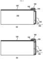
- FIG. 5 is a vertical cross-sectional view illustrating the battery cell assembly of FIG. 3 .
- a through-hole may be formed in the bus bar 130 and the bus bar frame 140, and the flame blocking member 150 may be coupled to the bus bar 130 to cover the through-hole.
- the flame blocking member 150 includes a first net structure 151 and a second net structure 152, and the first and second net structures 151, 152 are coupled to an outer surface of the bus bar 130 while being closely stacked on each other.
- the flame blocking member 150 includes the first net structure 151 welded to one surface of the bus bar 130 and located toward the inside of the cell cover 120 with respect to the bus bar 130, and the second net structure 152 welded to the other surface of the bus bar 130 and located toward the outside of the cell cover 120 with respect to the bus bar 130.
- first net structure 151, the bus bar 130, and the second net structure 152 are integrally coupled to each other.
- a separation space may function as a storage space of filtered particulate byproducts and may reduce ejection pressure of sparks.
- FIG. 6 is a perspective view illustrating a part of a battery cell assembly, according to a third embodiment.
- the bus bar 130 and the bus bar frame 140 are bent in an L shape.
- the bus bar 130 and the bus bar frame 140 include a first surface 141 erected and located at a front open end or a rear open end of the cell cover 120, and a second surface 142 bent from the first surface 141 and located on the cell cover 120.
- the terminal portion 160 is provided on the second surface 142.
- the area of the flame blocking member 150 may be wide, thereby further ensuring safety.
- the battery cell assemblies 100 may be electrically connected to each other by using the inter-bus bar K1 on the cell cover 120.
- an assembly process between the battery cell assemblies 100 may be easier, and a battery cell assembly structure may be more compact.
- FIG. 8 is a vertical cross-sectional view illustrating the battery cell assembly of FIG. 6 .
- the terminal portion 160 is formed on the second surface 142, and in the battery cell assembly 100, the flame blocking member 150 includes the first net structure 151 and the second net structure 152 and the first and second net structures 151, 152 are coupled to an outer surface of the bus bar 130 while being closely stacked on each other.
- an overall thickness of the flame blocking member may be reduced, thereby improving space utilization.
- the flame blocking member 150 includes the first net structure 151 and the second net structure 152, and the first net structure 151 is coupled to an inner surface of the bus bar 130 and the second net structure 152 is coupled to an outer surface of the bus bar 130 so that the first net structure 151 and the second net structure 152 are spaced apart from each other by a thickness of the bus bar 130. Even in this structure, the first net structure, the bus bar, and the second net structure are integrally coupled to each other.
- a separation space may function as a storage space of filtered particulate byproducts, and may reduce ejection pressure of sparks.
- FIG. 9 is a perspective view illustrating a battery cell assembly structure, according to the present disclosure.
- three battery cell assemblies 100 are mounted on a top surface of a base plate 210, and a support member 220 is located on side surfaces of the battery cell assemblies 100 in the full-length direction L.
- a fixing member 230 for fixing positions of the battery cell assemblies 100 is added to partially surround top and side surfaces of the battery cell assemblies and coupled to the support member 220.
- a crossbeam may be located at the position of the support member 220, to achieve a rigidity reinforcing effect, or the battery cell assembly structure may be located between chasses of a device to which the battery cell assembly structure is attached.
- a plurality of coupling portions 221 may be formed on the support member 220, and the fixing member 230 may include a metal band or a cover having a large area.
- the fixing member 230 may be coupled to the coupling portion 221 by using bolt fastening or welding.
- the battery cell assembly structure may be configured by locating a compression pad or a thermally conductive resin between the battery cell assembly structure and a chassis and directly fixing battery cell assemblies.
- the number of battery cell assemblies illustrated in FIG. 9 is merely an example, and when necessary, the number of battery cell assemblies may be freely changed and applied.
- FIG. 10 is a perspective view illustrating a battery cell assembly, according to a fourth embodiment of the present disclosure.
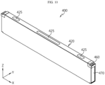
- FIG. 11 is a perspective view illustrating a cell cover of FIG. 10 and a pouch-type battery cell surrounded by the cell cover.
- FIG. 12 is a view illustrating a modified example of a venting hole portion of the cell cover of FIG. 10 .
- FIG. 13 is an exploded view illustrating elements of the battery cell assembly of FIG. 10 .
- FIG. 14 is a perspective view illustrating a bus bar to which a flame blocking member of FIG. 13 is applied.
- FIG. 15 is a cross-sectional view illustrating a portion of the battery cell assembly of FIG. 10 .
- a battery cell assembly 400 includes a pouch-type battery cell 410, a cell cover 420 surrounding the pouch-type battery cell 410, a bus bar 430 including a flame blocking member 450, a bus bar frame 440, and a fire-resistant insulating cover 470.
- the cell cover 420 may partially surround the pouch-type battery cell 410.
- An exterior member of the pouch-type battery cell 410 is formed of a soft material, and thus, the pouch-type battery cell 410 is more vulnerable to external impact and lower hardness than the can-type battery cell. Accordingly, when the pouch-type battery cell 410 is accommodated in a module case (not shown) of a battery module or a pack case (not shown) of a battery pack by omitting the module case, it is difficult to ensure safety or fixability against impact. However, in the present disclosure, because the pouch-type battery cell 410 may be surrounded by the cell cover 420 and then directly accommodated in the module case or the pack case, a stacked state may be stably maintained.
- the cell cover 420 may partially surround the pouch-type battery cell 410 so that at least a side of the pouch-type battery cell 410 is exposed to the outside.
- the cell cover 420 may surround only a portion of the pouch-type battery cell 410, without completely surrounding the pouch-type battery cell 410.
- the pouch-type battery cell 410 may be accommodated in the cell cover 420 in a state where a receiving portion (a portion of the pouch-type battery cell 410 in which an electrode assembly is received) is erected perpendicular to the ground.
- the cell cover 420 may surround the pouch-type battery cell 410 so that a lower edge portion of the pouch-type battery cell 410 and an electrode lead are exposed.
- the pouch-type battery cell 410 may be formed in a substantially hexahedral shape.
- Electrode leads 411 that is, a negative electrode lead and a positive electrode lead, may be respectively formed on two surfaces (front and rear surfaces in an ⁇ X direction) of six surfaces.
- the cell cover 420 may surround at least a part of three surfaces (e.g., a top surface, a left surface, and a right surface) of the remaining four surfaces excluding the two surfaces of the pouch-type battery cell 410 on which the electrode leads are formed.
- the cell cover 420 may include an upper cover portion 421, a first side cover portion 422, and a second side cover portion 423.
- the upper cover portion 421 may surround an upper edge portion of the pouch-type battery cell 410.
- the upper cover portion 421 may contact or be spaced apart from the upper edge portion of the pouch-type battery cell 410.
- the first side cover portion 422 may extend long downward from an edge that extends in a longitudinal direction (X direction) of the upper cover portion 421, to surround a side surface of a receiving portion of the pouch-type battery cell 410.
- the receiving portion may be a portion of a pouch exterior member in which an electrode assembly is received.
- the first side cover portion 422 may surround a left surface of the receiving portion of the pouch-type battery cell 410.
- the second side cover portion 423 may extend long downward from the other edge that extends in the longitudinal direction (X direction) of the upper cover portion 421, to surround the other surface of the receiving portion of the pouch-type battery cell 410. Also, the second side cover portion 423 may be spaced apart from the first side cover portion 422 by a certain interval and may be substantially symmetrical to the first side cover portion 422. For example, when one pouch-type battery cell 410 is accommodated in the cell cover 420, the second side cover portion 423 may surround a right surface of the receiving portion of the pouch-type battery cell 410.
- an inner space may be defined by the upper cover portion 421, the first side cover portion 422, and the second side cover portion 423.
- the cell cover 420 may accommodate one or more battery cells 410 in this defined inner space.
- the cell cover 420 may be formed of any of various materials, to ensure rigidity.
- the cell cover 420 may be formed of a metal material.
- the cell cover 420 may be formed of a steel material, especially, a stainless steel (SUS) material.
- the cell cover 420 may be entirely formed of a stainless steel (SUS) material.
- the cell cover 420 when the cell cover 420 is formed of a steel material, because the cell cover 420 has excellent mechanical strength or rigidity, a stacked state of the pouch-type battery cells 410 may be more stably supported. Also, in this case, damage or breakage of the pouch-type battery cell 410 from external impact, for example, a needle body, may be more effectively prevented. Also, in this case, handling of the pouch-type battery cell 410 may be easier.
- the cell cover 420 may surround the pouch-type battery cell 410 as shown in FIG. 11 , and may be directly seated on a bottom surface (not shown) of the module case or a bottom surface (not shown) of the pack case.
- the cell cover 420 is formed of a metal material having excellent rigidity such as steel, especially an SUS material, a self-sustaining state may be more stably maintained. Accordingly, in this case, a standing state of the pouch-type battery cells 410 may be more reliably supported.
- the pouch-type battery cells 410 may be more directly and effectively cooled. That is, heat emitted from the pouch-type battery cell 410 may be directly transferred to the module case or the pack case, thereby improving cooling performance.
- a thermally conductive resin may be located between the lower edge portion of the pouch-type battery cell 410 and the bottom surface of the module case or the bottom surface of the pack case, to increase thermal conductivity.
- the cell cover 420 may include a venting hole 425.
- the venting hole 425 may allow gas generated in the pouch-type battery cell 410 surrounded by the cell cover 420 to be discharged to the outside of the cell cover 420.
- the venting hole 425 may be formed at any of various positions of the cell cover 420.
- the venting hole 425 may be formed in the upper cover portion 421, as shown in FIGS. 10 and 11 .
- the venting hole 425 may be formed in an elliptical shape, a circular shape, a quadrangular shape, a diamond shape, or a rhombus shape.
- a plurality of venting holes 425 may be formed in the cell cover 420.
- a plurality of venting holes 425 may be formed in the upper cover portion 421 in a left-right direction and a front-back direction.
- a discharge direction when a flame or gas is discharged through the venting hole 425, a discharge direction may be controlled.
- gas or flame may be discharged upward (Z direction) without being directed to other pouch-type battery cells 410 or other battery cell assemblies 400 stacked in a horizontal direction. Accordingly, propagation of gas or flame between cells may be effectively prevented.
- this upward venting configuration may be more effective in suppressing a fire.
- a fire extinguishing tank (not shown) in which a fire extinguishing agent is accommodated is located over the cell cover 420, when a flame or gas is discharged upward from the cell cover 420, the fire extinguishing agent may leak out of the fire extinguishing tank, to prevent or delay a fire.
- the cell cover may include a flame arrestor 426 coupled to the venting hole.
- the flame arrestor 426 may include one or more mesh nets formed of a metal material with high rigidity and high heat resistance.
- the flame arrestor 426 may include a plurality of mesh nets having different hole sizes, and the plurality of mesh nets may have a stacked structure.
- the plurality of mesh nets (see FIG. 12 ) having smaller hole sizes may be sequentially dispsoed in a height direction. In this embodiment, the emission of a flame and high-temperature particles may be minimized and a temperature of venting gas may be effectively lowered.
- the bus bar frame 440 may support the bus bar 430 and may be coupled to the cell cover 420.
- the bus bar frame 440 may be coupled to each of the front open end and the rear open end of the cell cover 420.
- the bus bar frame 440 may be fixedly coupled to each of the front open end or the rear open end of the cell cover 420 through any of various fastening methods such as adhesion, welding, fitting, hook, bolting, or riveting.
- the bus bar frame 440 may be formed of an electrically insulating material, and may cover the front open end or the rear open end of the cell cover 420.
- the bus bar 430 may be counted on an outer surface of the bus bar frame 440.
- the bus bar frame 440 may include a slit through which the electrode lead 411 may pass, and the electrode lead 411 may pass through the slit, may be withdrawn out of the bus bar frame 440, and may be fixedly coupled to the bus bar 430 by using welding or the like.
- the bus bar 430 connected to the electrode lead 411 may be shielded by the insulating cover 470 so as not to be exposed to the outside.
- the insulating cover 470 may be formed of a flame retardant material having electrical insulation and excellent fire resistance.
- the bus bar 430 may include the flame blocking member 450.
- the flame blocking member 450 may be integrally formed with the bus bar 430, as shown in FIG. 14 .
- the bus bar 430 and the flame blocking member 450 may be integrally manufactured by welding or bonding.
- the flame blocking member 450 may have a net structure in which one or more mesh nets formed of a material with high rigidity/high heat resistance (e.g., copper or stainless) are stacked.
- the bus bar 430 may include a through-hole, and the flame blocking member 450 may be applied to the inside of the through-hole.
- the bus bar 430 may be provided so that the through-hole is filled with the flame blocking member 450 having a net structure in which multiple mesh nets are stacked. That is, the flame blocking member may be filled in the through-hole of the bus bar 430.
- a flame or high-temperature gas may be cooled while passing through the flame blocking member 450.
- a flame or high-temperature particles may be filtered by the flame blocking member 450, and thus, may be prevented from being discharged. Accordingly, according to the embodiment of the present disclosure, at least a flame or high-temperature particles may be prevented from being discharged in the full-length direction ( ⁇ direction) of the battery cell assembly 400.
- the bus bar 430 includes an upper end that is bent in the horizontal direction.
- the bent upper end may function as a (positive electrode or negative electrode) terminal portion 460 of the battery cell assembly 400.
- the positive electrode terminal portion and the negative electrode terminal portion are each located at an upper corner of the cell cover 420, when a cable or a connection means is mounted on the terminal portion 460 of the battery cell assembly 400, the cable or the connection means may be located on an upper portion of the battery cell assembly 400.
- the battery cell assembly may be easily accommodated in the module case or the pack case.
- the cell cover 420 includes a cut-out portion 424 at each of both ends in the full-length direction.
- the cut-out portion 424 may be formed by cutting each of upper corner portions of both ends of the cell cover 420 in the full-length direction.
- the bus bar frame 440 may be further pushed into the front open end or the rear open end of the cell cover 420, and the terminal portion 430 of the bus bar 430 may be exposed to an upper portion of the cell cover 420 through the cut-out portion 424.
- the bus bar 430 may include a lead coupling portion 431 vertically extending when being erected on the ground and to which an electrode lead is attached, a bent portion 432 obliquely extending at a certain angle from the lead coupling portion 431, and the terminal portion 460 horizontally extending from an upper end of the bent portion 432 in a direction away from the bent portion 432.
- the electrode lead 411 and the bus bar 430 may be connected in a state where the bus bar frame 440 and the bus bar 430 are inserted into the cell cover 420 as much as possible, and the terminal portion 460 of the bus bar 430 may face the upper portion of the cell cover 420. Accordingly, the battery cell assembly 400 of the present disclosure may have an overall length less than that of the battery cell assembly 100 according to the above embodiment, even when the pouch-type battery cell 410 of the same size is used.
- a battery cell assembly structure includes a plurality of battery cell assemblies 400 that are stacked in one direction.
- Adjacent battery cell assemblies 400 may be electrically connected to each other by the inter-bus bar K1.
- adjacent battery cell assemblies 400 may be stacked so that positive electrode terminal portions and negative electrode terminal portions are located in opposite directions.
- the battery cell assemblies 400 may be connected in series.
- the pouch-type battery cells 410 included in each battery cell assembly 400 may be connected in parallel, and the battery cell assemblies 400 may be connected in series.
- a battery module according to the present disclosure may include a plurality of battery cell assemblies 400 that are stacked and a module case in which the plurality of battery cell assemblies are received.
- a battery pack according to the present disclosure may include the battery modules that are connected in series and/or in parallel, and a pack case including the battery modules.
- the battery pack according to the present disclosure may omit a battery module unit, and may have a cell-to-pack structure in which the stacked plurality of battery cell assemblies 400 are directly accommodated in the pack case.
- a vehicle according to the present disclosure may include the battery pack according to the present disclosure.
- the vehicle according to the present disclosure may include a certain vehicle using electricity as a driving source such as an electric vehicle or a hybrid vehicle.
- the vehicle according to the present disclosure may include various other elements included in a vehicle, for example, a vehicle body or a motor, in addition to the battery pack according to the present disclosure.
Landscapes
- Chemical & Material Sciences (AREA)
- Chemical Kinetics & Catalysis (AREA)
- Electrochemistry (AREA)
- General Chemical & Material Sciences (AREA)
- Engineering & Computer Science (AREA)
- Composite Materials (AREA)
- Inorganic Chemistry (AREA)
- Manufacturing & Machinery (AREA)
- Physics & Mathematics (AREA)
- Condensed Matter Physics & Semiconductors (AREA)
- General Physics & Mathematics (AREA)
- Materials Engineering (AREA)
- Aviation & Aerospace Engineering (AREA)
- Battery Mounting, Suspending (AREA)
- Connection Of Batteries Or Terminals (AREA)
- Gas Exhaust Devices For Batteries (AREA)
- Secondary Cells (AREA)
Abstract
Description
- The present disclosure relates to a battery cell assembly including a bus bar with a flame blocking member and a battery cell assembly structure including the battery cell assembly. More particularly, the present disclosure relates to a battery cell assembly including a bus bar to which a flame blocking member is added to prevent thermal runaway due to ignition of a battery cell from spreading to adjacent battery cells, and a battery cell assembly structure including the battery cell assembly.
- The present application claims priority to
Korean Patent Application No. 10-2022-0002978 filed on January 7, 2022 - Lithium secondary batteries that may be charged and discharged are used not only as energy sources for small devices such as mobile devices, but also as energy sources for medium and large-sized devices such as electric vehicles and power storage devices with the development of technology for increasing capacity and improving safety.
- As lithium secondary batteries are used as high-capacity and high-power energy sources, ensuring the safety of lithium secondary batteries has become an important issue of interest.
- Because a normal charging and discharging process of a lithium secondary battery is a heating process, a temperature of the secondary battery is inevitably increased, and the temperature increase of the secondary battery may degrade the performance of a battery cell.
- Also, a lithium secondary battery has a risk of explosion due to overheating, and when a flame caused by the explosion spreads to adjacent battery cells, it is difficult to suppress a fire until they are burned down. When thermal runaway occurs in a battery cell, a flame, particles, and gas venting above an ignition point may be generated, and the flame, etc. may propagate to adjacent battery cells, which may eventually lead to the explosion of the battery cell.
- Accordingly, it is important to prevent additional damage due to the explosion of the battery cell by lowering the temperature and preventing the spread of the flame, sparks, etc. generated in the battery cell.
- In this regard,
Korean Patent Application Publication No. 2020-0059024 - However, the prior art 1 has a problem in that, because the thermal insulation pad is added to cover the portion where the electrode lead and the bus bar are welded, a size of the battery module is increased by a thickness of the thermal insulation pad.
-
Korean Patent Application Publication No. 2017-0014309 - Accordingly, there is a need to develop a structure in which, when a pouch-type battery cell is included, a flame may be prevented from being discharged to an electrode lead and propagating to adjacent battery cells, and an increase in an overall volume may be minimized.
- The present disclosure is designed to solve the problems of the related art, and therefore the present disclosure is directed to providing a battery cell assembly in which a temperature of a flame, high-temperature particles, and gas generated in an ignited battery cell may be lowered and thermal runaway may be prevented from spreading to other adjacent battery cell assemblies, and a battery cell assembly structure including the battery cell assembly.
- However, technical objectives to be achieved by the present disclosure are not limited thereto, and other unmentioned technical objectives will be apparent to one of ordinary skill in the art from the description of the present disclosure.
- According to the present disclosure, there is provided a battery cell assembly including at least one pouch-type battery cell, a cell cover surrounding the at least one pouch-type battery cell, a bus bar connected to an electrode lead of the at least one pouch-type battery cell, and a bus bar frame supporting the bus bar and covering a front open end or a rear open end of the cell cover where the electrode lead is located in the cell cover, wherein a flame blocking member including a mesh net formed of a material with high rigidity and high heat resistance is coupled to a body of the bus bar.
- Each of the at least one pouch-type battery cell may be a bidirectional battery cell in which a positive electrode lead and a negative electrode lead protrude in opposite directions from both ends in a full-length direction, wherein the cell cover has a quadrangular frame shape surrounding four outer surfaces excluding a direction in which the positive electrode lead and the negative electrode lead protrude, or an n-like frame shape surrounding three outer surfaces of the four outer surfaces.
- The flame blocking member may be integrally coupled to the bus bar.
- The flame blocking member may be formed so that a plurality of net structures, each including a mesh net formed of a material with high rigidity and high heat resistance, overlap each other.
- The flame blocking member may include a first net structure welded to one surface of the bus bar and located toward an inside of the cell cover with respect to the bus bar, and a second net structure welded to the other surface of the bus bar and located toward an outside of the cell cover with respect to the bus bar.
- The bus bar may include a through-hole in the body, wherein the through-hole is covered by the flame blocking member.
- The flame blocking member may have a net structure in which a plurality of mesh nets are stacked, and may be filled in the through-hole.
- The bus bar may include a terminal portion for electrical connection with another adjacent battery cell assembly, wherein the terminal portion is a portion of the bus bar extending upward beyond the flame blocking member.
- The bus bar may include a terminal portion for electrical connection with another adjacent battery cell assembly, wherein the terminal portion is located on the cell cover.
- The bus bar and the bus bar frame may include a first surface erected and located at the front open end or the rear open end of the cell cover, and a second surface bent from the first surface and located on the cell cover, wherein the terminal portion is provided on the second surface.
- The flame blocking member may be formed of a copper or stainless steel material.
- The at least one pouch-type battery cell may be accommodated in a state where a receiving portion (a portion where an electrode assembly is received) is erected perpendicular to a ground, wherein the cell cover includes an upper cover portion surrounding an upper edge portion of the at least one pouch-type battery cell, a first side cover portion surrounding a side surface of the receiving portion of the at least one pouch-type battery cell, and a second side cover portion surrounding the other surface of the receiving portion of the at least one pouch-type battery cell.
- The cover portion of the cell cover may include at least one venting hole through which gas is discharged.
- A flame arrestor including one or more mesh nets may be coupled to the at least one venting hole.
- The cell cover may include a cut-out portion formed by cutting each of upper corner portions of both ends of the cell cover in a full-length direction, wherein the bus bar includes a terminal portion exposed to an upper portion of the cell cover through the cut-out portion and functioning as a positive electrode terminal or a negative electrode terminal of the battery cell assembly.
- According to another aspect of the present disclosure, there is provided a battery cell assembly structure including a base plate on which battery cell assemblies are mounted, a support member located on side surfaces of the battery cell assemblies in a full-length direction, and a fixing member added to fix positions of the battery cell assemblies and coupled to the support member.
- According to another aspect of the present disclosure, there is provided a battery pack including the battery cell assembly.
- According to another aspect of the present disclosure, there is provided an electric vehicle including the battery cell assembly.
- According to an aspect of the present disclosure, a flame or high-temperature particles generated due to ignition of a battery cell may be prevented from being indiscriminately discharged in a full-length direction of a battery cell assembly where a bus bar is located.
- In particular, according to an aspect of the present disclosure, because a flame, high-temperature particles, and high-temperature gas ejected from a battery cell may be cooled while passing through a flame blocking member, and some may be blocked from being discharged, the risk of external ignition or propagation of heat sources may be reduced.
- Also, according to an aspect of the present disclosure, because a soft pouch-type battery cell is accommodated in a cell cover, the pouch-type battery cell may be protected from external impact and may be prevented from being damaged or broken during a handing process.
- Also, according to an aspect of the present disclosure, when a thermal event occurs in a pouch-type battery cell, a discharge direction of gas or flame ejected from the pouch-type battery cell may be controlled to be an upward or downward direction. Accordingly, propagation of thermal runaway between adjacent battery cell assemblies may be effectively prevented.
- The present disclosure may have various other effects, which will be described in each embodiment, or descriptions of effects that may be easily inferred by one of ordinary skill in the art will be omitted.
-
-
FIG. 1 is a perspective view illustrating a battery cell assembly, according to a first embodiment. -
FIG. 2 is a front view illustrating battery cells to which a cell cover is added, according to the present disclosure. -
FIG. 3 is a perspective view illustrating a part of a battery cell assembly, according to a second embodiment. -
FIG. 4 is a view schematically illustrating a configuration of electrically connecting a plurality of battery cell assemblies ofFIG. 3 . -
FIG. 5 is a vertical cross-sectional view illustrating the battery cell assembly ofFIG. 3 . -
FIG. 6 is a perspective view illustrating a part of a battery cell assembly, according to a third embodiment. -
FIG. 7 is a view schematically illustrating a configuration of electrically connecting a plurality of battery cell assemblies ofFIG. 6 . -
FIG. 8 is a vertical cross-sectional view illustrating the battery cell assembly ofFIG. 6 . -
FIG. 9 is a perspective view illustrating a battery cell assembly structure, according to an embodiment of the present disclosure. -
FIG. 10 is a perspective view illustrating a battery cell assembly, according to a fourth embodiment of the present disclosure. -
FIG. 11 is a perspective view illustrating a cell cover ofFIG. 10 and a pouch-type battery cell surrounded by the cell cover. -
FIG. 12 is a view illustrating a modified example of a venting hole portion of the cell cover ofFIG. 10 . -
FIG. 13 is an exploded view illustrating elements of the battery cell assembly ofFIG. 10 . -
FIG. 14 is a perspective view illustrating a bus bar to which a flame blocking member ofFIG. 13 is applied. -
FIG. 15 is a cross-sectional view illustrating a portion of the battery cell assembly ofFIG. 10 . -
FIG. 16 is a view illustrating a portion of a battery cell assembly structure including the battery cell assembly ofFIG. 10 . - Now, preferred embodiments of the present disclosure will be described in detail with reference to the accompanying drawings such that the preferred embodiments of the present disclosure may be easily implemented by one of ordinary skill in the art to which the present disclosure pertains. In describing the principle of operation of the preferred embodiments of the present disclosure in detail, however, a detailed description of known functions and configurations incorporated herein will be omitted when the same may obscure the subject matter of the present disclosure.
- In addition, the same reference numbers will be used throughout the drawings to refer to parts that perform similar functions or operations. In the case in which one part is said to be connected to another part throughout the specification, not only may the one part be directly connected to the other part, but also, the one part may be indirectly connected to the other part via a further part. In addition, when a certain element is included, it does not mean that other elements are excluded, but means that such elements may be further included unless mentioned otherwise.
- In addition, a description to embody elements through limitation or addition may be applied to all disclosures, unless particularly restricted, and does not limit a specific disclosure.
- Also, in the description of the disclosure and the claims of the present application, singular forms are intended to include plural forms unless mentioned otherwise.
- Also, in the description of the disclosure and the claims of the present application, "or" includes "and" unless mentioned otherwise. Therefore, "including A or B" means three cases, namely, the case including A, the case including B, and the case including A and B.
-
FIG. 1 is a perspective view illustrating a battery cell assembly, according to a first embodiment. - Referring to
FIG. 1 , abattery cell assembly 100 according to the present disclosure includes at least one pouch-type battery cell 110, acell cover 120 at least partially surrounding the pouch-type battery cell 110, abus bar 130 connected to an electrode lead of the pouch-type battery cell 110, and abus bar frame 140 supporting thebus bar 130 and covering a front open end or a rear open end of thecell cover 120 where theelectrode lead 111 is located in thecell cover 111, and aflame blocking member 150 including a mesh net formed of a material with high rigidity/high heat resistance may be coupled to a body of thebus bar 130. - The pouch-
type battery cell 110 is long in a full-length direction L, and is a bidirectional battery cell in which a positive electrode lead and a negative electrode lead protrude in opposite directions from both ends in the full-length direction L. - Accordingly, the
bus bar frame 140, thebus bar 130, and theflame blocking member 150 are provided at each of both ends in the full-length direction L where theelectrode lead 111 extends. - The
bus bar frame 140 may be formed of an insulating material, and may be coupled to both ends of thecell cover 120 in the full-length direction to cover an open end of thecell cover 120. Thebus bar 130 is formed of a metal material having electrical conductivity, and is attached to an outer surface of thebus bar frame 140. - A
slit 143 through which anelectrode lead 111 may pass may be formed in thebus bar frame 140, and theelectrode lead 111 may pass through theslit 143, may be withdrawn out of thebus bar frame 140, may be bent to face thebus bar 130, and may be fixedly coupled to thebus bar 130 by using welding or the like. - In detail, a through-hole may be formed in the
bus bar 130, and theflame blocking member 150 may be mounted on thebus bar 130 to completely cover the through-hole. - The number and shape of battery cells illustrated in
FIG. 1 are merely examples, and a size and shape of thebus bar 130 may vary according to the number ofbattery cells 110 coupled to thebus bar 130 and a series/parallel connection state of thebattery cells 110. - The
flame blocking member 150 may be integrally coupled to thebus bar 130 by using welding or the like. In detail, theflame blocking member 150 may include one net structure, or may include a plurality of net structures, for example, two, or three or more net structures, which overlap each other. - Alternatively, the
flame blocking member 150 may be indirectly mounted on thebus bar 130. In detail, theflame blocking member 150 may be located outside thebus bar frame 140 to which thebus bar 130 is coupled, and theflame blocking member 150 may include one, or two or more net structures. When theflame blocking member 150 includes two or more net structures, a fixing plate located between the net structures to fix positions of the net structures to be spaced apart from each other, and a case in which the net structures and the fixing plate are accommodated may be provided. Also, an insulating cover for insulation between the case and theelectrode lead 111 coupled to the bus bar may be located between thebus bar frame 140 and the case. That is, theflame blocking member 150 including a net structure may be accommodated in the case, and the case may be coupled to thebus bar frame 140 to which thebus bar 130 is coupled. As such, when theflame blocking member 150 is accommodated in a separate case and then is coupled to the bus bar frame, theflame blocking member 150 may be directly mounted on thebus bar 130. - Because the
flame blocking member 150 according to the present disclosure includes a plurality of net structures that overlap each other, a flame, particles, and gas generated due to ignition of thebattery cell 110 may be cooled while passing through the plurality of net structures. Also, the flame or particles may be filtered by the net structures and may be prevented from being discharged to the outside. - In detail, particulate byproducts generated during ignition of the
battery cell 110 are ejected as particles. When a plurality of net structures are applied to a direction in which the particles are ejected, particulate byproducts may be filtered, and thus, the particles may be prevented from being discharged to the outside. - Also, when a plurality of net structures having different mesh sizes overlap each other, the effect of filtering particulate byproducts of various sizes may be improved, and thus, additional ignition of
adjacent battery cells 110 due to the particles may be prevented. - Also, when passing through a net structure having a small mesh size, the area of sparks contacting the net structure is increased, thereby achieving an instantaneous cooling effect.
- Furthermore, the
flame blocking member 150 according to the present disclosure may prevent a flame, particles, or gas generated outside thebattery cell 110 from spreading to thebattery cell 110. - The
flame blocking member 150 may be formed of a material with high rigidity and high heat resistance to block a flame, sparks, and gas, for example, copper or stainless steel. -
FIG. 2 is a front view illustrating thebattery cells 110 to which thecell cover 120 is added, according to the present disclosure. - Referring to
FIG. 2 , thecell cover 120 shown in (a) has a quadrangular frame shape surrounding four outer surfaces excluding a direction in which theelectrode lead 111 protrudes, and thecell cover 120 shown in (b) has an n-like frame shape surrounding the remaining three outer surfaces excluding the bottom surface from among the four outer surfaces excluding the direction in which theelectrode lead 111 protrudes. When thecell cover 120 having the n-like frame shape is provided, a separate member for mounting thebattery cell assembly 100 or a heat transfer member may be applied to the bottom surface to which thecell cover 120 is not applied. - In the case of using the
cell cover 120 of the present disclosure, when the pouch-type battery cell 110 is ignited, a flame or sparks may be intensively ejected in a full-length direction. - Accordingly, in the present disclosure, because the
flame blocking member 150 is provided at each of both ends of the outer surface of the pouch-type battery cell 110 where theelectrode lead 111 is located in the full-length direction, a flame or sparks may be prevented from being discharged to the outside of thebattery cell 110. Accordingly, a series of thermal runaway may be prevented. -
FIG. 3 is a perspective view illustrating a part of a battery cell assembly, according to a second embodiment. - Referring to
FIG. 3 , thebus bar frame 140 has a flat shape, and thebus bar 130 is coupled to thebus bar frame 140. Theelectrode lead 111 is coupled to thebus bar 130 for electrical connection, and theflame blocking member 150 is located between electrode lead coupling portions to which theelectrode lead 111 is coupled. - Also, the
bus bar 130 may include aterminal portion 160 over theflame blocking member 150. Theterminal portion 160 is a portion of thebus bar 130 extending upward beyond theflame blocking member 150, and is used to electrically connect different battery cell assemblies. For example, as shown inFIG. 4 , adjacentbattery cell assemblies 100 may be electrically connected to each other by an inter-bus bar K1. -
FIG. 5 is a vertical cross-sectional view illustrating the battery cell assembly ofFIG. 3 . - Referring to
FIG. 5 , a through-hole may be formed in thebus bar 130 and thebus bar frame 140, and theflame blocking member 150 may be coupled to thebus bar 130 to cover the through-hole. - Referring to (a) of
FIG. 5 , in the battery cell assembly, theflame blocking member 150 includes a firstnet structure 151 and a secondnet structure 152, and the first and secondnet structures bus bar 130 while being closely stacked on each other. - When a plurality of net structures are closely stacked as described above, an overall thickness of the
flame blocking member 150 is reduced, thereby improving space utilization. - Referring to (b) of
FIG. 5 , theflame blocking member 150 includes the firstnet structure 151 welded to one surface of thebus bar 130 and located toward the inside of thecell cover 120 with respect to thebus bar 130, and the secondnet structure 152 welded to the other surface of thebus bar 130 and located toward the outside of thecell cover 120 with respect to thebus bar 130. - Even in this structure, the first
net structure 151, thebus bar 130, and the secondnet structure 152 are integrally coupled to each other. - When a plurality of net structures are spaced apart from each other as described above, a separation space may function as a storage space of filtered particulate byproducts and may reduce ejection pressure of sparks.
-
FIG. 6 is a perspective view illustrating a part of a battery cell assembly, according to a third embodiment. - Referring to
FIG. 6 , thebus bar 130 and thebus bar frame 140 are bent in an L shape. In detail, thebus bar 130 and thebus bar frame 140 include afirst surface 141 erected and located at a front open end or a rear open end of thecell cover 120, and asecond surface 142 bent from thefirst surface 141 and located on thecell cover 120. Theterminal portion 160 is provided on thesecond surface 142. - Because the
terminal portion 160 is provided on thesecond surface 142, the area of theflame blocking member 150 may be wide, thereby further ensuring safety. - Also, as shown in
FIG. 7 , thebattery cell assemblies 100 may be electrically connected to each other by using the inter-bus bar K1 on thecell cover 120. In this case, an assembly process between thebattery cell assemblies 100 may be easier, and a battery cell assembly structure may be more compact. -
FIG. 8 is a vertical cross-sectional view illustrating the battery cell assembly ofFIG. 6 . - Referring to (a) of
FIG. 8 , theterminal portion 160 is formed on thesecond surface 142, and in thebattery cell assembly 100, theflame blocking member 150 includes the firstnet structure 151 and the secondnet structure 152 and the first and secondnet structures bus bar 130 while being closely stacked on each other. - When a plurality of net structures are closely stacked as described above, an overall thickness of the flame blocking member may be reduced, thereby improving space utilization.
- Referring to (b) of
FIG. 8 , in the battery cell assembly, theflame blocking member 150 includes the firstnet structure 151 and the secondnet structure 152, and the firstnet structure 151 is coupled to an inner surface of thebus bar 130 and the secondnet structure 152 is coupled to an outer surface of thebus bar 130 so that the firstnet structure 151 and the secondnet structure 152 are spaced apart from each other by a thickness of thebus bar 130. Even in this structure, the first net structure, the bus bar, and the second net structure are integrally coupled to each other. - When a plurality of net structures are spaced apart from each other as described above, a separation space may function as a storage space of filtered particulate byproducts, and may reduce ejection pressure of sparks.
-
FIG. 9 is a perspective view illustrating a battery cell assembly structure, according to the present disclosure. - Referring to
FIG. 9 , threebattery cell assemblies 100 are mounted on a top surface of abase plate 210, and asupport member 220 is located on side surfaces of thebattery cell assemblies 100 in the full-length direction L. A fixingmember 230 for fixing positions of thebattery cell assemblies 100 is added to partially surround top and side surfaces of the battery cell assemblies and coupled to thesupport member 220. - Alternatively, instead of the
support member 220 ofFIG. 9 , a crossbeam may be located at the position of thesupport member 220, to achieve a rigidity reinforcing effect, or the battery cell assembly structure may be located between chasses of a device to which the battery cell assembly structure is attached. - A plurality of
coupling portions 221 may be formed on thesupport member 220, and the fixingmember 230 may include a metal band or a cover having a large area. The fixingmember 230 may be coupled to thecoupling portion 221 by using bolt fastening or welding. - Alternatively, when separate structures such as the fixing
member 230 and thecoupling portion 221 are not included, the battery cell assembly structure may be configured by locating a compression pad or a thermally conductive resin between the battery cell assembly structure and a chassis and directly fixing battery cell assemblies. - The number of battery cell assemblies illustrated in
FIG. 9 is merely an example, and when necessary, the number of battery cell assemblies may be freely changed and applied. -
FIG. 10 is a perspective view illustrating a battery cell assembly, according to a fourth embodiment of the present disclosure.FIG. 11 is a perspective view illustrating a cell cover ofFIG. 10 and a pouch-type battery cell surrounded by the cell cover.FIG. 12 is a view illustrating a modified example of a venting hole portion of the cell cover ofFIG. 10 .FIG. 13 is an exploded view illustrating elements of the battery cell assembly ofFIG. 10 .FIG. 14 is a perspective view illustrating a bus bar to which a flame blocking member ofFIG. 13 is applied.FIG. 15 is a cross-sectional view illustrating a portion of the battery cell assembly ofFIG. 10 . - Referring to
FIGS. 10 to 15 , abattery cell assembly 400 according to the fourth embodiment of the present disclosure includes a pouch-type battery cell 410, acell cover 420 surrounding the pouch-type battery cell 410, abus bar 430 including aflame blocking member 450, abus bar frame 440, and a fire-resistantinsulating cover 470. - As shown in
FIG. 11 , thecell cover 420 may partially surround the pouch-type battery cell 410. - An exterior member of the pouch-
type battery cell 410 is formed of a soft material, and thus, the pouch-type battery cell 410 is more vulnerable to external impact and lower hardness than the can-type battery cell. Accordingly, when the pouch-type battery cell 410 is accommodated in a module case (not shown) of a battery module or a pack case (not shown) of a battery pack by omitting the module case, it is difficult to ensure safety or fixability against impact. However, in the present disclosure, because the pouch-type battery cell 410 may be surrounded by thecell cover 420 and then directly accommodated in the module case or the pack case, a stacked state may be stably maintained. - The
cell cover 420 may partially surround the pouch-type battery cell 410 so that at least a side of the pouch-type battery cell 410 is exposed to the outside. For example, thecell cover 420 may surround only a portion of the pouch-type battery cell 410, without completely surrounding the pouch-type battery cell 410. - For example, the pouch-
type battery cell 410 may be accommodated in thecell cover 420 in a state where a receiving portion (a portion of the pouch-type battery cell 410 in which an electrode assembly is received) is erected perpendicular to the ground. As shown inFIG. 11 , thecell cover 420 may surround the pouch-type battery cell 410 so that a lower edge portion of the pouch-type battery cell 410 and an electrode lead are exposed. - In other words, the pouch-
type battery cell 410 may be formed in a substantially hexahedral shape. Electrode leads 411, that is, a negative electrode lead and a positive electrode lead, may be respectively formed on two surfaces (front and rear surfaces in an ±X direction) of six surfaces. Thecell cover 420 may surround at least a part of three surfaces (e.g., a top surface, a left surface, and a right surface) of the remaining four surfaces excluding the two surfaces of the pouch-type battery cell 410 on which the electrode leads are formed. - In more detail, as shown in
FIG. 11 , thecell cover 420 may include anupper cover portion 421, a firstside cover portion 422, and a secondside cover portion 423. - The
upper cover portion 421 may surround an upper edge portion of the pouch-type battery cell 410. Theupper cover portion 421 may contact or be spaced apart from the upper edge portion of the pouch-type battery cell 410. - The first
side cover portion 422 may extend long downward from an edge that extends in a longitudinal direction (X direction) of theupper cover portion 421, to surround a side surface of a receiving portion of the pouch-type battery cell 410. The receiving portion may be a portion of a pouch exterior member in which an electrode assembly is received. For example, when one pouch-type battery cell 410 is accommodated in thecell cover 420, the firstside cover portion 422 may surround a left surface of the receiving portion of the pouch-type battery cell 410. - The second
side cover portion 423 may extend long downward from the other edge that extends in the longitudinal direction (X direction) of theupper cover portion 421, to surround the other surface of the receiving portion of the pouch-type battery cell 410. Also, the secondside cover portion 423 may be spaced apart from the firstside cover portion 422 by a certain interval and may be substantially symmetrical to the firstside cover portion 422. For example, when one pouch-type battery cell 410 is accommodated in thecell cover 420, the secondside cover portion 423 may surround a right surface of the receiving portion of the pouch-type battery cell 410. - In this embodiment, an inner space may be defined by the
upper cover portion 421, the firstside cover portion 422, and the secondside cover portion 423. Thecell cover 420 may accommodate one ormore battery cells 410 in this defined inner space. - The
cell cover 420 may be formed of any of various materials, to ensure rigidity. In particular, thecell cover 420 may be formed of a metal material. When thecell cover 420 is formed of a metal material, a stacked state of the pouch-type battery cells 410 may be more stably maintained, and the pouch-type battery cells 410 may be more safely protected from external impact. In particular, thecell cover 420 may be formed of a steel material, especially, a stainless steel (SUS) material. For example, thecell cover 420 may be entirely formed of a stainless steel (SUS) material. - As such, when the
cell cover 420 is formed of a steel material, because thecell cover 420 has excellent mechanical strength or rigidity, a stacked state of the pouch-type battery cells 410 may be more stably supported. Also, in this case, damage or breakage of the pouch-type battery cell 410 from external impact, for example, a needle body, may be more effectively prevented. Also, in this case, handling of the pouch-type battery cell 410 may be easier. - The
cell cover 420 may surround the pouch-type battery cell 410 as shown inFIG. 11 , and may be directly seated on a bottom surface (not shown) of the module case or a bottom surface (not shown) of the pack case. In this case, because thecell cover 420 is formed of a metal material having excellent rigidity such as steel, especially an SUS material, a self-sustaining state may be more stably maintained. Accordingly, in this case, a standing state of the pouch-type battery cells 410 may be more reliably supported. - Also, because the lower edge portion of the pouch-
type battery cell 410 may directly contact the bottom surface of the module case or the bottom surface of the pack case through an open lower end of thecell cover 420, the pouch-type battery cells 410 may be more directly and effectively cooled. That is, heat emitted from the pouch-type battery cell 410 may be directly transferred to the module case or the pack case, thereby improving cooling performance. In this case, a thermally conductive resin may be located between the lower edge portion of the pouch-type battery cell 410 and the bottom surface of the module case or the bottom surface of the pack case, to increase thermal conductivity. - Also, the
cell cover 420 may include aventing hole 425. Theventing hole 425 may allow gas generated in the pouch-type battery cell 410 surrounded by thecell cover 420 to be discharged to the outside of thecell cover 420. Theventing hole 425 may be formed at any of various positions of thecell cover 420. For example, the ventinghole 425 may be formed in theupper cover portion 421, as shown inFIGS. 10 and11 . Theventing hole 425 may be formed in an elliptical shape, a circular shape, a quadrangular shape, a diamond shape, or a rhombus shape. - Also, a plurality of venting
holes 425 may be formed in thecell cover 420. For example, a plurality of ventingholes 425 may be formed in theupper cover portion 421 in a left-right direction and a front-back direction. - According to this embodiment of the present disclosure, when a flame or gas is discharged through the
venting hole 425, a discharge direction may be controlled. For example, as in the embodiment, when theventing hole 425 is formed in theupper cover portion 421, gas or flame may be discharged upward (Z direction) without being directed to other pouch-type battery cells 410 or otherbattery cell assemblies 400 stacked in a horizontal direction. Accordingly, propagation of gas or flame between cells may be effectively prevented. - In particular, when a fire extinguishing agent or the like is located over the
cell cover 420, this upward venting configuration may be more effective in suppressing a fire. For example, assuming that a fire extinguishing tank (not shown) in which a fire extinguishing agent is accommodated is located over thecell cover 420, when a flame or gas is discharged upward from thecell cover 420, the fire extinguishing agent may leak out of the fire extinguishing tank, to prevent or delay a fire. - In
FIG. 12 , the cell cover, as a modified example of the cell cover ofFIG. 10 , may include aflame arrestor 426 coupled to the venting hole. Theflame arrestor 426 may include one or more mesh nets formed of a metal material with high rigidity and high heat resistance. For example, theflame arrestor 426 may include a plurality of mesh nets having different hole sizes, and the plurality of mesh nets may have a stacked structure. The plurality of mesh nets (seeFIG. 12 ) having smaller hole sizes may be sequentially dispsoed in a height direction. In this embodiment, the emission of a flame and high-temperature particles may be minimized and a temperature of venting gas may be effectively lowered. - The
bus bar frame 440 may support thebus bar 430 and may be coupled to thecell cover 420. For example, referring toFIGS. 10 and13 , thebus bar frame 440 may be coupled to each of the front open end and the rear open end of thecell cover 420. For example, thebus bar frame 440 may be fixedly coupled to each of the front open end or the rear open end of thecell cover 420 through any of various fastening methods such as adhesion, welding, fitting, hook, bolting, or riveting. - Also, the
bus bar frame 440 may be formed of an electrically insulating material, and may cover the front open end or the rear open end of thecell cover 420. Thebus bar 430 may be counted on an outer surface of thebus bar frame 440. Also, thebus bar frame 440 may include a slit through which theelectrode lead 411 may pass, and theelectrode lead 411 may pass through the slit, may be withdrawn out of thebus bar frame 440, and may be fixedly coupled to thebus bar 430 by using welding or the like. - The
bus bar 430 connected to theelectrode lead 411 may be shielded by the insulatingcover 470 so as not to be exposed to the outside. The insulatingcover 470 may be formed of a flame retardant material having electrical insulation and excellent fire resistance. - In particular, the
bus bar 430 may include theflame blocking member 450. - The
flame blocking member 450 may be integrally formed with thebus bar 430, as shown inFIG. 14 . For example, thebus bar 430 and theflame blocking member 450 may be integrally manufactured by welding or bonding. Theflame blocking member 450 may have a net structure in which one or more mesh nets formed of a material with high rigidity/high heat resistance (e.g., copper or stainless) are stacked. - The
bus bar 430 may include a through-hole, and theflame blocking member 450 may be applied to the inside of the through-hole. In other words, thebus bar 430 may be provided so that the through-hole is filled with theflame blocking member 450 having a net structure in which multiple mesh nets are stacked. That is, the flame blocking member may be filled in the through-hole of thebus bar 430. - According to the
bus bar 430 including theflame blocking member 450, when a thermal event such as heat/fire of the pouch-type battery cell 410 occurs, a flame or high-temperature gas may be cooled while passing through theflame blocking member 450. Also, a flame or high-temperature particles may be filtered by theflame blocking member 450, and thus, may be prevented from being discharged. Accordingly, according to the embodiment of the present disclosure, at least a flame or high-temperature particles may be prevented from being discharged in the full-length direction (± direction) of thebattery cell assembly 400. - Also, the
bus bar 430 according to the present embodiment includes an upper end that is bent in the horizontal direction. The bent upper end may function as a (positive electrode or negative electrode)terminal portion 460 of thebattery cell assembly 400. In thebattery cell assembly 400 according to the present embodiment, because the positive electrode terminal portion and the negative electrode terminal portion are each located at an upper corner of thecell cover 420, when a cable or a connection means is mounted on theterminal portion 460 of thebattery cell assembly 400, the cable or the connection means may be located on an upper portion of thebattery cell assembly 400. In this case, because a space may be secured on front and rear sides of thebattery cell assembly 400, for example, the battery cell assembly may be easily accommodated in the module case or the pack case. - Referring back to
FIGS. 11 to 13 , thecell cover 420 includes a cut-outportion 424 at each of both ends in the full-length direction. The cut-outportion 424 may be formed by cutting each of upper corner portions of both ends of thecell cover 420 in the full-length direction. - In the
cell cover 420 including the cut-outportion 424, thebus bar frame 440 may be further pushed into the front open end or the rear open end of thecell cover 420, and theterminal portion 430 of thebus bar 430 may be exposed to an upper portion of thecell cover 420 through the cut-outportion 424. - Also, the
bus bar 430 according to the present embodiment may include alead coupling portion 431 vertically extending when being erected on the ground and to which an electrode lead is attached, abent portion 432 obliquely extending at a certain angle from thelead coupling portion 431, and theterminal portion 460 horizontally extending from an upper end of thebent portion 432 in a direction away from thebent portion 432. - According to this structure of the bus bar, the
electrode lead 411 and thebus bar 430 may be connected in a state where thebus bar frame 440 and thebus bar 430 are inserted into thecell cover 420 as much as possible, and theterminal portion 460 of thebus bar 430 may face the upper portion of thecell cover 420. Accordingly, thebattery cell assembly 400 of the present disclosure may have an overall length less than that of thebattery cell assembly 100 according to the above embodiment, even when the pouch-type battery cell 410 of the same size is used. - A battery cell assembly structure according to another embodiment of the present disclosure includes a plurality of
battery cell assemblies 400 that are stacked in one direction. - Adjacent
battery cell assemblies 400 may be electrically connected to each other by the inter-bus bar K1. For example, as shown inFIG. 16 , adjacentbattery cell assemblies 400 may be stacked so that positive electrode terminal portions and negative electrode terminal portions are located in opposite directions. When thebattery cell assemblies 400 are stacked in this pattern and the positive and the negative electrode terminal portions of adjacentbattery cell assemblies 420 are connected by the inter-bus bar K1, thebattery cell assemblies 400 may be connected in series. In this case, the pouch-type battery cells 410 included in eachbattery cell assembly 400 may be connected in parallel, and thebattery cell assemblies 400 may be connected in series. - A battery module according to the present disclosure may include a plurality of
battery cell assemblies 400 that are stacked and a module case in which the plurality of battery cell assemblies are received. - Also, a battery pack according to the present disclosure may include the battery modules that are connected in series and/or in parallel, and a pack case including the battery modules. In another example, the battery pack according to the present disclosure may omit a battery module unit, and may have a cell-to-pack structure in which the stacked plurality of
battery cell assemblies 400 are directly accommodated in the pack case. - A vehicle according to the present disclosure may include the battery pack according to the present disclosure. The vehicle according to the present disclosure may include a certain vehicle using electricity as a driving source such as an electric vehicle or a hybrid vehicle. Also, the vehicle according to the present disclosure may include various other elements included in a vehicle, for example, a vehicle body or a motor, in addition to the battery pack according to the present disclosure.
- It will be understood by one of ordinary skill in the art that when terms indicating directions such as upper, lower, left, right, front, and rear are used, these terms are only for convenience of explanation and may vary according to a position of a target object, a position of an observer, etc.
- Although the embodiments of the present disclosure have been illustrated and described above, the present disclosure is not limited to the above-described specific embodiments. Various modified embodiments may be made by one of ordinary skill in the art without departing from the scope of the present disclosure as claimed in the claims.
Claims (18)
- A battery cell assembly comprising:at least one pouch-type battery cell;a cell cover surrounding the at least one pouch-type battery cell;a bus bar connected to an electrode lead of the at least one pouch-type battery cell;
anda bus bar frame supporting the bus bar and covering a front open end or a rear open end of the cell cover where the electrode lead is located in the cell cover,wherein a flame blocking member comprising a mesh net formed of a material with high rigidity and high heat resistance is coupled to a body of the bus bar. - The battery cell assembly according to claim 1, wherein each of the at least one pouch-type battery cell is a bidirectional battery cell in which a positive electrode lead and a negative electrode lead protruding in opposite directions from both ends in a full-length direction,
wherein the cell cover has a quadrangular frame shape surrounding four outer surfaces excluding a direction in which the positive electrode lead and the negative electrode lead protrude, or an n-like frame shape surrounding three outer surfaces of the four outer surfaces. - The battery cell assembly according to claim 1, wherein the flame blocking member is integrally coupled to the bus bar.
- The battery cell assembly according to claim 1, wherein the flame blocking member is formed so that a plurality of net structures, each comprising a mesh net formed of a material with high rigidity and high heat resistance, overlap each other.
- The battery cell assembly according to claim 1, wherein the flame blocking member comprises:a first net structure welded to one surface of the bus bar and located toward an inside of the cell cover with respect to the bus bar; anda second net structure welded to the other surface of the bus bar and located toward an outside of the cell cover with respect to the bus bar.
- The battery cell assembly according to claim 1, wherein the bus bar comprises a through-hole in the body,
wherein the through-hole is covered by the flame blocking member. - The battery cell assembly according to claim 6, wherein the flame blocking member has a net structure in which a plurality of mesh nets are stacked, and is filled in the through-hole.
- The battery cell assembly according to claim 1, wherein the bus bar comprises a terminal portion for electrical connection with another adjacent battery cell assembly,
wherein the terminal portion is a portion of the bus bar extending upward beyond the flame blocking member. - The battery cell assembly according to claim 1, wherein the bus bar comprises a terminal portion for electrical connection with another adjacent battery cell assembly,
wherein the terminal portion is located on the cell cover. - The battery cell assembly according to claim 9, wherein the bus bar and the bus bar frame comprise a first surface erected and located at the front open end or the rear open end of the cell cover, and a second surface bent from the first surface and located on the cell cover,
wherein the terminal portion is provided on the second surface. - The battery cell assembly according to claim 1, wherein the flame blocking member is formed of a copper or stainless steel material.
- The battery cell assembly according to claim 1, wherein the at least one pouch-type battery cell is accommodated in a state where a receiving portion (a portion where an electrode assembly is received) is erected perpendicular to a ground,
wherein the cell cover comprises:an upper cover portion surrounding an upper edge portion of the at least one pouch-type battery cell;a first side cover portion surrounding a side surface of the receiving portion of the at least one pouch-type battery cell; anda second side cover portion surrounding the other surface of the receiving portion of the at least one pouch-type battery cell. - The battery cell assembly according to claim 12, wherein the upper cover portion of the cell cover comprises at least one venting hole through which gas is discharged.
- The battery cell assembly according to claim 13, wherein a flame arrestor comprising one or more mesh nets is coupled to the at least one venting hole.
- The battery cell assembly according to claim 1, wherein the cell cover comprises a cut-out portion formed by cutting each of upper corner portions of both ends of the cell cover in a full-length direction,
wherein the bus bar comprises a terminal portion exposed to an upper portion of the cell cover through the cut-out portion and functioning as a positive electrode terminal or a negative electrode terminal of the battery cell assembly. - A battery cell assembly structure comprising:a base plate on which battery cell assemblies according to any one of claims 1 to 15 are mounted;a support member located on side surfaces of the battery cell assemblies in a full-length direction; anda fixing member added to fix positions of the battery cell assemblies and coupled to the support member.
- A battery pack comprising the battery cell assembly structure according to claim 16.
- An electric vehicle comprising the battery cell assembly structure according to claim 16.
Applications Claiming Priority (2)
| Application Number | Priority Date | Filing Date | Title |
|---|---|---|---|
| KR20220002978 | 2022-01-07 | ||
| PCT/KR2022/020739 WO2023132519A1 (en) | 2022-01-07 | 2022-12-19 | Battery cell assembly comprising bus bar to which flame blocking member is added and battery cell assembly structure comprising same |
Publications (3)
| Publication Number | Publication Date |
|---|---|
| EP4270631A1 true EP4270631A1 (en) | 2023-11-01 |
| EP4270631A4 EP4270631A4 (en) | 2024-12-11 |
| EP4270631B1 EP4270631B1 (en) | 2026-02-04 |
Family
ID=87073972
Family Applications (1)
| Application Number | Title | Priority Date | Filing Date |
|---|---|---|---|
| EP22919056.6A Active EP4270631B1 (en) | 2022-01-07 | 2022-12-19 | Battery cell assembly including bus bar to which flame blocking member is added and battery cell assembly structure including the battery cell assembly |
Country Status (6)
| Country | Link |
|---|---|
| US (2) | US20240396158A1 (en) |
| EP (1) | EP4270631B1 (en) |
| JP (1) | JP7670849B2 (en) |
| KR (1) | KR20230107120A (en) |
| CN (1) | CN116762229A (en) |
| WO (1) | WO2023132519A1 (en) |
Families Citing this family (5)
| Publication number | Priority date | Publication date | Assignee | Title |
|---|---|---|---|---|
| KR20250012224A (en) * | 2023-07-17 | 2025-01-24 | 주식회사 엘지에너지솔루션 | Secondary battery |
| KR20250074348A (en) * | 2023-11-20 | 2025-05-27 | 주식회사 엘지에너지솔루션 | Battery module, Battery pack and vehicle including the same |
| WO2025116462A1 (en) * | 2023-12-01 | 2025-06-05 | 주식회사 엘지에너지솔루션 | Battery assembly and battery pack comprising same |
| KR20250145970A (en) * | 2024-03-29 | 2025-10-13 | 에스케이온 주식회사 | Battery module |
| KR20250177748A (en) * | 2024-06-17 | 2025-12-24 | 주식회사 엘지에너지솔루션 | Battery cell assembly |
Family Cites Families (18)
| Publication number | Priority date | Publication date | Assignee | Title |
|---|---|---|---|---|
| JP3884872B2 (en) * | 1998-10-28 | 2007-02-21 | 株式会社オートネットワーク技術研究所 | Circuit breaker |
| JP2009211909A (en) * | 2008-03-04 | 2009-09-17 | Panasonic Corp | Battery, battery pack, and method of manufacturing connection terminals used therefor |
| WO2016132404A1 (en) * | 2015-02-16 | 2016-08-25 | 三洋電機株式会社 | Power source device |
| KR102072098B1 (en) | 2015-07-29 | 2020-01-31 | 주식회사 엘지화학 | Secondary battery, battery module and battery pack with improved safety |
| KR101866026B1 (en) * | 2016-06-20 | 2018-06-08 | 한국광기술원 | Busbar for bonding battery cell and method for battery cell using the same |
| CN106674916A (en) * | 2016-12-29 | 2017-05-17 | 广东生益科技股份有限公司 | A flame-retardant resin composition and the adhesive prepared therefrom, an insulating adhesive film for laminated busbars, and a method for preparing the insulating adhesive film |
| KR102757247B1 (en) | 2018-11-20 | 2025-01-17 | 주식회사 엘지에너지솔루션 | Battery module |
| KR102698844B1 (en) * | 2018-12-04 | 2024-08-23 | 주식회사 엘지에너지솔루션 | Battery pack |
| KR102380225B1 (en) * | 2019-03-06 | 2022-03-28 | 주식회사 엘지에너지솔루션 | A ESS module having a structure capable of preventing external exposure of a flame and a ESS pack comprising the same |
| EP3962932A4 (en) | 2019-05-02 | 2023-05-10 | Board of Regents, The University of Texas System | SYSTEM AND METHOD FOR ENHANCEMENT OF SYNTHESIZED PROTEIN STABILITY |
| KR102751111B1 (en) * | 2019-06-17 | 2025-01-06 | 주식회사 엘지에너지솔루션 | Battery Module Comprising Base Plate having Gas Discharge Passage and Battery Pack and Energy Storage System |
| KR102748983B1 (en) * | 2019-07-03 | 2024-12-30 | 주식회사 엘지에너지솔루션 | Battery Module Including Flame Retardant Plate, Battery Rack and Power Storage Device Including the Same |
| KR102805857B1 (en) * | 2019-10-10 | 2025-05-12 | 주식회사 엘지에너지솔루션 | Battery Module Comprising Heat Insulating Member and Battery Pack Including the Same |
| KR102928723B1 (en) * | 2020-01-15 | 2026-02-19 | 주식회사 엘지에너지솔루션 | Battery Module Including Flame Retardant Sheet, Battery Rack Including the Same, and Power Storage System |
| CN211670261U (en) * | 2020-02-28 | 2020-10-13 | 湖北亿纬动力有限公司 | Bus bar insulation structure |
| KR102931493B1 (en) * | 2020-04-01 | 2026-02-25 | 주식회사 엘지에너지솔루션 | Battery module and battery pack including the same |
| KR102798544B1 (en) * | 2020-04-01 | 2025-04-18 | 주식회사 엘지에너지솔루션 | Battery module and battery pack including the same |
| JP7329181B2 (en) * | 2020-06-04 | 2023-08-18 | トヨタ自動車株式会社 | Battery units, battery modules and battery packs |
-
2022
- 2022-12-19 EP EP22919056.6A patent/EP4270631B1/en active Active
- 2022-12-19 WO PCT/KR2022/020739 patent/WO2023132519A1/en not_active Ceased
- 2022-12-19 KR KR1020220178542A patent/KR20230107120A/en active Pending
- 2022-12-19 JP JP2023556548A patent/JP7670849B2/en active Active
- 2022-12-19 US US18/267,770 patent/US20240396158A1/en active Pending
- 2022-12-19 CN CN202280011835.XA patent/CN116762229A/en active Pending
-
2023
- 2023-09-07 US US18/463,186 patent/US20240213549A1/en active Pending
Also Published As
| Publication number | Publication date |
|---|---|
| EP4270631B1 (en) | 2026-02-04 |
| US20240396158A1 (en) | 2024-11-28 |
| US20240213549A1 (en) | 2024-06-27 |
| KR20230107120A (en) | 2023-07-14 |
| WO2023132519A1 (en) | 2023-07-13 |
| JP2024512930A (en) | 2024-03-21 |
| EP4270631A4 (en) | 2024-12-11 |
| JP7670849B2 (en) | 2025-04-30 |
| CN116762229A (en) | 2023-09-15 |
Similar Documents
| Publication | Publication Date | Title |
|---|---|---|
| EP4270631B1 (en) | Battery cell assembly including bus bar to which flame blocking member is added and battery cell assembly structure including the battery cell assembly | |
| KR102800926B1 (en) | A battery pack with a structure that reduces the temperature of venting gas and blocks the emission of sparks into outside of pack case | |
| JP2024507463A (en) | Battery pack with pack case fitted with cooling fins | |
| JP7761770B2 (en) | Safety-enhanced battery module | |
| JP7751064B2 (en) | Battery module with flame propagation blocking structure and battery pack including the same | |
| EP4203156A1 (en) | Battery pack and vehicle including same | |
| KR102953670B1 (en) | Battery module that can suppress the emission of gas or flame through the connector in case of internal ignition | |
| KR102960242B1 (en) | Battery module and battery pack including the same | |
| CN114270619A (en) | Battery module and battery pack including the same | |
| JP2024546057A (en) | Battery pack and device including same | |
| US20250202038A1 (en) | Battery pack | |
| EP4383415A1 (en) | Battery pack | |
| KR102799774B1 (en) | Battery pack and vehicle including the same | |
| KR20230039122A (en) | Battery module with improved thermal runaway transition prevention performance | |
| JP2024546809A (en) | Battery pack, battery module and automobile including same | |
| JP7802930B2 (en) | Battery pack and automobile including same | |
| EP4576385A1 (en) | Battery module | |
| KR102956627B1 (en) | Battery module and Battery Pack including the same | |
| EP4425663A1 (en) | Battery module with improved flame-retardant connector | |
| CN118830129A (en) | Battery pack with enhanced safety | |
| JP7861228B2 (en) | Battery module, battery pack including said battery module, and automobile | |
| KR102911142B1 (en) | Battery pack, battery module and vehicle including the same | |
| KR102965601B1 (en) | Battery module, battery pack and vehicle comprising the same | |
| EP4726894A1 (en) | Battery pack and vehicle including same | |
| JP2026509047A (en) | Battery module, battery pack including said battery module, and automobile |
Legal Events
| Date | Code | Title | Description |
|---|---|---|---|
| STAA | Information on the status of an ep patent application or granted ep patent |
Free format text: STATUS: THE INTERNATIONAL PUBLICATION HAS BEEN MADE |
|
| PUAI | Public reference made under article 153(3) epc to a published international application that has entered the european phase |
Free format text: ORIGINAL CODE: 0009012 |
|
| STAA | Information on the status of an ep patent application or granted ep patent |
Free format text: STATUS: REQUEST FOR EXAMINATION WAS MADE |
|
| 17P | Request for examination filed |
Effective date: 20230725 |
|
| AK | Designated contracting states |
Kind code of ref document: A1 Designated state(s): AL AT BE BG CH CY CZ DE DK EE ES FI FR GB GR HR HU IE IS IT LI LT LU LV MC ME MK MT NL NO PL PT RO RS SE SI SK SM TR |
|
| A4 | Supplementary search report drawn up and despatched |
Effective date: 20241111 |
|
| RIC1 | Information provided on ipc code assigned before grant |
Ipc: H01M 50/211 20210101ALI20241105BHEP Ipc: H01M 50/502 20210101ALI20241105BHEP Ipc: H01M 50/591 20210101AFI20241105BHEP |
|
| DAV | Request for validation of the european patent (deleted) | ||
| DAX | Request for extension of the european patent (deleted) | ||
| GRAP | Despatch of communication of intention to grant a patent |
Free format text: ORIGINAL CODE: EPIDOSNIGR1 |
|
| STAA | Information on the status of an ep patent application or granted ep patent |
Free format text: STATUS: GRANT OF PATENT IS INTENDED |
|
| INTG | Intention to grant announced |
Effective date: 20250902 |
|
| GRAS | Grant fee paid |
Free format text: ORIGINAL CODE: EPIDOSNIGR3 |
|
| GRAA | (expected) grant |
Free format text: ORIGINAL CODE: 0009210 |
|
| STAA | Information on the status of an ep patent application or granted ep patent |
Free format text: STATUS: THE PATENT HAS BEEN GRANTED |
|
| P01 | Opt-out of the competence of the unified patent court (upc) registered |
Free format text: CASE NUMBER: UPC_APP_0016372_4270631/2025 Effective date: 20251209 |
|
| AK | Designated contracting states |
Kind code of ref document: B1 Designated state(s): AL AT BE BG CH CY CZ DE DK EE ES FI FR GB GR HR HU IE IS IT LI LT LU LV MC ME MK MT NL NO PL PT RO RS SE SI SK SM TR |
|
| REG | Reference to a national code |
Ref country code: CH Ref legal event code: F10 Free format text: ST27 STATUS EVENT CODE: U-0-0-F10-F00 (AS PROVIDED BY THE NATIONAL OFFICE) Effective date: 20260204 Ref country code: GB Ref legal event code: FG4D |
|
| REG | Reference to a national code |
Ref country code: IE Ref legal event code: FG4D |
|
| REG | Reference to a national code |
Ref country code: DE Ref legal event code: R096 Ref document number: 602022029979 Country of ref document: DE |