EP4270623A1 - Battery box and battery module - Google Patents
Battery box and battery module Download PDFInfo
- Publication number
- EP4270623A1 EP4270623A1 EP22817862.0A EP22817862A EP4270623A1 EP 4270623 A1 EP4270623 A1 EP 4270623A1 EP 22817862 A EP22817862 A EP 22817862A EP 4270623 A1 EP4270623 A1 EP 4270623A1
- Authority
- EP
- European Patent Office
- Prior art keywords
- pressure relief
- plate
- relief cavity
- cavity
- region
- Prior art date
- Legal status (The legal status is an assumption and is not a legal conclusion. Google has not performed a legal analysis and makes no representation as to the accuracy of the status listed.)
- Granted
Links
Images


Classifications
-
- H—ELECTRICITY
- H01—ELECTRIC ELEMENTS
- H01M—PROCESSES OR MEANS, e.g. BATTERIES, FOR THE DIRECT CONVERSION OF CHEMICAL ENERGY INTO ELECTRICAL ENERGY
- H01M50/00—Constructional details or processes of manufacture of the non-active parts of electrochemical cells other than fuel cells, e.g. hybrid cells
- H01M50/30—Arrangements for facilitating escape of gases
- H01M50/35—Gas exhaust passages comprising elongated, tortuous or labyrinth-shaped exhaust passages
- H01M50/367—Internal gas exhaust passages forming part of the battery cover or case; Double cover vent systems
-
- H—ELECTRICITY
- H01—ELECTRIC ELEMENTS
- H01M—PROCESSES OR MEANS, e.g. BATTERIES, FOR THE DIRECT CONVERSION OF CHEMICAL ENERGY INTO ELECTRICAL ENERGY
- H01M50/00—Constructional details or processes of manufacture of the non-active parts of electrochemical cells other than fuel cells, e.g. hybrid cells
- H01M50/20—Mountings; Secondary casings or frames; Racks, modules or packs; Suspension devices; Shock absorbers; Transport or carrying devices; Holders
- H01M50/204—Racks, modules or packs for multiple batteries or multiple cells
- H01M50/207—Racks, modules or packs for multiple batteries or multiple cells characterised by their shape
- H01M50/213—Racks, modules or packs for multiple batteries or multiple cells characterised by their shape adapted for cells having curved cross-section, e.g. round or elliptic
-
- H—ELECTRICITY
- H01—ELECTRIC ELEMENTS
- H01M—PROCESSES OR MEANS, e.g. BATTERIES, FOR THE DIRECT CONVERSION OF CHEMICAL ENERGY INTO ELECTRICAL ENERGY
- H01M50/00—Constructional details or processes of manufacture of the non-active parts of electrochemical cells other than fuel cells, e.g. hybrid cells
- H01M50/20—Mountings; Secondary casings or frames; Racks, modules or packs; Suspension devices; Shock absorbers; Transport or carrying devices; Holders
- H01M50/218—Mountings; Secondary casings or frames; Racks, modules or packs; Suspension devices; Shock absorbers; Transport or carrying devices; Holders characterised by the material
- H01M50/22—Mountings; Secondary casings or frames; Racks, modules or packs; Suspension devices; Shock absorbers; Transport or carrying devices; Holders characterised by the material of the casings or racks
- H01M50/222—Inorganic material
- H01M50/224—Metals
-
- H—ELECTRICITY
- H01—ELECTRIC ELEMENTS
- H01M—PROCESSES OR MEANS, e.g. BATTERIES, FOR THE DIRECT CONVERSION OF CHEMICAL ENERGY INTO ELECTRICAL ENERGY
- H01M50/00—Constructional details or processes of manufacture of the non-active parts of electrochemical cells other than fuel cells, e.g. hybrid cells
- H01M50/20—Mountings; Secondary casings or frames; Racks, modules or packs; Suspension devices; Shock absorbers; Transport or carrying devices; Holders
- H01M50/289—Mountings; Secondary casings or frames; Racks, modules or packs; Suspension devices; Shock absorbers; Transport or carrying devices; Holders characterised by spacing elements or positioning means within frames, racks or packs
- H01M50/291—Mountings; Secondary casings or frames; Racks, modules or packs; Suspension devices; Shock absorbers; Transport or carrying devices; Holders characterised by spacing elements or positioning means within frames, racks or packs characterised by their shape
-
- H—ELECTRICITY
- H01—ELECTRIC ELEMENTS
- H01M—PROCESSES OR MEANS, e.g. BATTERIES, FOR THE DIRECT CONVERSION OF CHEMICAL ENERGY INTO ELECTRICAL ENERGY
- H01M50/00—Constructional details or processes of manufacture of the non-active parts of electrochemical cells other than fuel cells, e.g. hybrid cells
- H01M50/30—Arrangements for facilitating escape of gases
- H01M50/383—Flame arresting or ignition-preventing means
-
- H—ELECTRICITY
- H01—ELECTRIC ELEMENTS
- H01M—PROCESSES OR MEANS, e.g. BATTERIES, FOR THE DIRECT CONVERSION OF CHEMICAL ENERGY INTO ELECTRICAL ENERGY
- H01M2220/00—Batteries for particular applications
- H01M2220/20—Batteries in motive systems, e.g. vehicle, ship, plane
-
- H—ELECTRICITY
- H01—ELECTRIC ELEMENTS
- H01M—PROCESSES OR MEANS, e.g. BATTERIES, FOR THE DIRECT CONVERSION OF CHEMICAL ENERGY INTO ELECTRICAL ENERGY
- H01M50/00—Constructional details or processes of manufacture of the non-active parts of electrochemical cells other than fuel cells, e.g. hybrid cells
- H01M50/20—Mountings; Secondary casings or frames; Racks, modules or packs; Suspension devices; Shock absorbers; Transport or carrying devices; Holders
- H01M50/204—Racks, modules or packs for multiple batteries or multiple cells
-
- H—ELECTRICITY
- H01—ELECTRIC ELEMENTS
- H01M—PROCESSES OR MEANS, e.g. BATTERIES, FOR THE DIRECT CONVERSION OF CHEMICAL ENERGY INTO ELECTRICAL ENERGY
- H01M50/00—Constructional details or processes of manufacture of the non-active parts of electrochemical cells other than fuel cells, e.g. hybrid cells
- H01M50/20—Mountings; Secondary casings or frames; Racks, modules or packs; Suspension devices; Shock absorbers; Transport or carrying devices; Holders
- H01M50/289—Mountings; Secondary casings or frames; Racks, modules or packs; Suspension devices; Shock absorbers; Transport or carrying devices; Holders characterised by spacing elements or positioning means within frames, racks or packs
-
- Y—GENERAL TAGGING OF NEW TECHNOLOGICAL DEVELOPMENTS; GENERAL TAGGING OF CROSS-SECTIONAL TECHNOLOGIES SPANNING OVER SEVERAL SECTIONS OF THE IPC; TECHNICAL SUBJECTS COVERED BY FORMER USPC CROSS-REFERENCE ART COLLECTIONS [XRACs] AND DIGESTS
- Y02—TECHNOLOGIES OR APPLICATIONS FOR MITIGATION OR ADAPTATION AGAINST CLIMATE CHANGE
- Y02E—REDUCTION OF GREENHOUSE GAS [GHG] EMISSIONS, RELATED TO ENERGY GENERATION, TRANSMISSION OR DISTRIBUTION
- Y02E60/00—Enabling technologies; Technologies with a potential or indirect contribution to GHG emissions mitigation
- Y02E60/10—Energy storage using batteries
Definitions
- the present application relates to the field of power batteries, for example, to a battery box body and a battery module.
- a battery box body of a large cylindrical battery includes an accommodating cavity configured to accommodate battery cells, and is provided with a pressure relief valve. When a thermal runaway occurs in the battery cells, substances enter the pressure relief valve from the accommodating cavity. A pressure relief path is relatively short, and cooling effect is not ideal during a pressure relief process. High-temperature substances sprayed are easy to burn and heat spread, resulting in fire hazards.
- the present application provides a battery box body and a battery module to reduce a temperature of high-temperature substances, so that the temperature of the high-temperature substances is lower than an ignition point when the high-temperature substances reach at a pressure relief valve, thereby preventing from firing and improving safety and reliability.
- a battery box body including a base plate assembly and a side beam assembly disposed surrounding the base plate assembly, where the base plate assembly is divided into a first region and a second region, battery cells are disposed in the first region, and a support plate is disposed in the second region;
- a battery module including battery cells and the battery box body mentioned above, wherein the battery cells are disposed in the first region.
- a first feature is disposed “on” or “under” a second feature may include a direct contact between the first feature and the second feature, or a contact between the first feature and the second feature through other features rather than the direct contact.
- that the first feature is disposed “up”, “above” and “on” the second feature includes that the first feature is right above or obliquely above the second feature, or only indicate that a horizontal height of the first feature is greater than a horizontal height of the second feature.
- That the first feature is disposed "under”, “below”, or “underneath” of the second feature include that the first feature is right below or obliquely below the second feature, or only indicate that the horizontal height of the first feature is less than the horizontal height of the second feature.
- the embodiment provides a battery module, including an electrical component, battery cells, and a battery box body. Both the electrical component and the battery cells are accommodated in the battery box body. In order to prevent individual battery cell in the battery module from runaway to damage other battery cells, the electrical component, and control systems, etc., the embodiment provides a battery box body.
- the battery box body includes a base plate assembly 1 and a side beam assembly 2 disposed surrounding the base plate assembly 1, where the base plate assembly 1 is divided into a first region M and a second region N, the battery cells are disposed in the first region M, and a support plate 3 is disposed in the second region N.
- the base plate assembly 1 includes an outer plate 11 and an inner plate 12, where a first pressure relief cavity 1A is defined by the outer plate 11 and the inner plate 12, the battery cells are occluded on a portion of a cavity wall of the first pressure relief cavity 1A.
- a second pressure relief cavity 3A is defined by the support plate 3 and the inner plate 12, and other portion of the cavity wall of the first pressure relief cavity 1A is communicated with the second pressure relief cavity 3A.
- a third pressure relief cavity 2A is defined by an inner cavity of the side beam assembly 2, the second pressure relief cavity 3A is communicated with the third pressure relief cavity 2A, and the side beam assembly 2 is installed with a pressure relief valve 4 communicated with the third pressure relief cavity 2A.
- a pressure relief channel is defined by the first pressure relief cavity 1A, the second pressure relief cavity 3A, and the third pressure relief cavity 2A, and after passing through the pressure relief channel, the high-temperature substances are relieved through a pressure relief valve 4.
- three pressure relief cavity structures respectively take away a large amount of heat to form three times of cooling, and when the high-temperature substances reach at the pressure relief valve 4 of the box body, a temperature of the high-temperature substances are lower than an ignition point to prevent fire, which is more safe and reliable.
- the inner plate 12 includes a carrier plate 121 and a spacing plate 122, where each of the battery cells is occluded at a side of a corresponding one of first through hole 1211 defined in the carrier plate 121, and the high-temperature substances sprayed from the battery cells where the thermal runaway occurs enter the first pressure relief cavity 1A through the first through holes 1211 and are diffused, so as to realize that the first pressure relief cavity 1A is separated from the battery cells.
- the battery cells are cylindrical battery cells
- the first through holes 1211 are circular holes
- a bottom area of each of the cylindrical battery cells is not less than a cross-sectional area of a corresponding one of the first through holes 1211, to ensure that the high-temperature substances enter the first pressure relief cavity 1A as much as possible, and to prevent leakage of the substances from affecting other battery cells.
- a plurality of first through holes 1211 are disposed in the carrier plate 121 and arranged in a form such as a plurality of rows or a matrix, so that the carrier plate 121 is a honeycomb plate.
- the battery cells may also be square battery cells, etc., and structures such as the carrier plate 121 and the first through holes 1211 may be disposed accordingly, the embodiment is not limited thereto.
- the second pressure relief cavity 3A is defined by the spacing plate 122 and the support plate 3, and the first pressure relief cavity 1A is communicated with the second pressure relief cavity 3A through second through holes defined in the spacing plate 122.
- a strainer plate 13 is disposed on the second through holes defined in the spacing plate 122, and a plurality of smaller holes are defined on the strainer plate 13 to prevent large particulate substances from entering the second pressure relief cavity 3A, thereby preventing the pressure relief channel from being blocked by the high-temperature substances sprayed from the battery cells, and resulting in unsmooth pressure relief.
- the high-temperature substances are filtered through the strainer plate 13, and the strainer plate 13 may be replaced periodically in a later period.
- a phase change material layer is affixed on the strainer plate 13, and the temperature of the high-temperature substances may be reduced through the phase change material layer.
- the outer plate 11 is a steel plate with a high melting point, is not easy to melt, and may reduce the temperature of the high-temperature substances.
- isolation walls 21 are disposed in the third pressure relief cavity 2A, so that the third pressure relief cavity 2A includes a plurality of cavities communicated with each other, and a plurality of isolation walls 21 may be arranged in parallel and at intervals to form an s-shaped cavity.
- the plurality of isolation walls 21 are arranged at intervals, and the isolation walls 21 may have included angles to form the plurality of cavities, holes are defined in the isolation walls 21, and the cavities are communicated with each other.
- the plurality of isolation walls 21 are disposed with different shapes, such as one or a combined shape of T-shaped, L-shaped, a plurality of continuous L-shaped, cross-shaped, and concave-shaped, ect., so that the third pressure relief cavity 2A forms a "labyrinth" cavity structure, and a structural shape and a splicing shape of the isolation walls 21 may be referred to related art to form a labyrinth with a simple shape or a complex shape, the embodiment is not limited thereto.
- a length of the third pressure relief cavity 2A is increased, and pressure relief time is prolonged, thereby reducing the temperature of the high-temperature substances.
- a cross section of the second region N is an isosceles trapezoid
- the side beam assembly 2 includes a first side beam 22 and second side beams 23 symmetrically communicated with both ends of the first side beam 22
- pressure relief holes 2311 are defined in the second side beams 22
- the second pressure relief cavity 3A is communicated with the third pressure relief cavity 2A through the pressure relief holes 2311.
- the pressure relief holes 2311 are defined on two symmetrical second side beams 23, the high-temperature substances are respectively output from the two second side beams 23 to two sides to disperse the high-temperature substances, which is beneficial to reduce the temperature.
- each of the second side beams 23 has an L-shaped cross section, and includes a horizontal side beam 231 and a vertical side beam 232 communicated with each other.
- the horizontal side beam 231 is located in the second region N, and the second pressure relief cavity 3A is communicated with the horizontal side beam 231.
- the length of the third pressure relief cavity 2A is prolonged by disposing the L-shaped side beam assembly 2.
- the horizontal side beam 231 is provided with a plurality of cavities arranged along a horizontal direction
- the vertical side beam 232 is provided with a plurality of cavities arranged along a vertical direction
- the isolation walls 21 are provided with openings to communicate between the cavities.
- the two second side beams 23 are symmetrical along a symmetrical plane
- two pressure relief valves 4 are provided and installed on the side beam assembly 2 and located at a side of the first region M away from the second region N to prolong a conveying path of the high-temperature substances
- the two pressure relief valves 4 are symmetrical along the symmetrical plane. That is, the two side beams 23 and the two pressure relief valves 4 are symmetrical along the same symmetrical plane, so that pressure relief pressure of each of the two pressure relief valves 4 is reduced to improve reliability.
- the side beam assembly 2 further includes a fourth side beam 25 parallel to the first side beam 22, and a third side beam 24 to connect the second side beam 23 with the fourth side beam 25, where the pressure relief valve 4 is installed on the fourth side beam 25, and a output path of the high-temperature substances in the third pressure relief cavity 2A is defined by the second side beam 23, the third side beam 24, the fourth side beam 25, and the pressure relief valves 4 located on a corresponding side.
- the battery box body further includes a connection plate 5 and a fastener 6, where the fastener 6 passes through the connection plate 5, the base plate assembly 1, and the side beam assembly 2 in sequence, so that the connection plate 5, the base plate assembly 1, and the side beam assembly 2 are connected with each other.
- the battery box body further includes a first crossbeam 8, where the first crossbeam 8 is configured to divide the first region M into a plurality of installation regions, and each of the installation regions is configured to install a group of the battery cells, so that the battery cells are arranged in groups to realize cell to pack, a number of components is reduced, and cost is reduced; and the first cross beam 8 is connected to the base plate assembly 1 and the side beam assembly 2 by a fixing member 7 to improve structural strength.
- the fixing member 7 may be a combination of a long screw and a nut, where the long screw penetrates through the base plate assembly 1 and the first cross beam 8, the nut abuts against a side of the base plate assembly 1 away from the first cross beam 8.
- the first crossbeam 8 is a cross beam.
- the cross beam divides the first region M into four installation regions to improve the structural strength.
- a plurality of first crossbeams 8 may be provided to divide the first region M into eight installation regions or more.
- the plurality of first crossbeams 8 may be arranged in parallel and at intervals, so that the plurality of installation regions may be arranged in a row or a column according to usage requirements, the embodiment is not limited to thereto.
- the battery box body further includes a second crossbeam 9, where the second crossbeam 9 is provided to separate the first region M from the second region N, and the second region N is configured to install the electrical component, so as to prevent the electrical component, a control system and the like from being damaged when the thermal runaway occurs in the battery cells.
- the second crossbeam 9 may also be connected to the base plate assembly 1 by the fixing member 7.
Landscapes
- Chemical & Material Sciences (AREA)
- Chemical Kinetics & Catalysis (AREA)
- Electrochemistry (AREA)
- General Chemical & Material Sciences (AREA)
- Inorganic Chemistry (AREA)
- Battery Mounting, Suspending (AREA)
Abstract
Description
- This application claims priority to
Chinese Patent Application Serial No. 202210419599.7, filed on April 20, 2022 - The present application relates to the field of power batteries, for example, to a battery box body and a battery module.
- A battery box body of a large cylindrical battery includes an accommodating cavity configured to accommodate battery cells, and is provided with a pressure relief valve. When a thermal runaway occurs in the battery cells, substances enter the pressure relief valve from the accommodating cavity. A pressure relief path is relatively short, and cooling effect is not ideal during a pressure relief process. High-temperature substances sprayed are easy to burn and heat spread, resulting in fire hazards.
- The present application provides a battery box body and a battery module to reduce a temperature of high-temperature substances, so that the temperature of the high-temperature substances is lower than an ignition point when the high-temperature substances reach at a pressure relief valve, thereby preventing from firing and improving safety and reliability.
- A battery box body is provided, including a base plate assembly and a side beam assembly disposed surrounding the base plate assembly, where the base plate assembly is divided into a first region and a second region, battery cells are disposed in the first region, and a support plate is disposed in the second region;
- the base plate assembly includes an outer plate and an inner plate, a first pressure relief cavity is defined by the outer plate and the inner plate, and the battery cells are occluded on a portion of a cavity wall of the first pressure relief cavity;
- a second pressure relief cavity is defined by the support plate and the inner plate, and other portion of the cavity wall of the first pressure relief cavity is communicated with the second pressure relief cavity; and
- a third pressure relief cavity is defined by an inner cavity of the side beam assembly, the second pressure relief cavity is communicated with the third pressure relief cavity, and the side beam assembly is installed with a pressure relief valve communicated with the third pressure relief cavity.
- A battery module is provided, including battery cells and the battery box body mentioned above, wherein the battery cells are disposed in the first region.
-
-
FIG. 1 is a schematic structural view of a battery box body in a view angle provided by an embodiment of the present application; -
FIG. 2 is a cross-sectional view in A-A direction ofFIG. 1 ; -
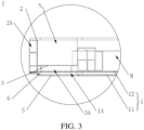
FIG. 3 is an enlarged view at I ofFIG. 2 ; -
FIG. 4 is a schematic structural view of a battery box body in another view angle provided by an embodiment of the present application; -
FIG. 5 is a schematic structural view of a second side beam provided by an embodiment of the present application. - In the above figures:
- 1. Base plate assembly; 11. Outer plate; 12. Inner plate; 121. Carrier plate; 1211. First through hole; 122. Spacing plate; 13. Strainer plate; 1A. First pressure relief cavity;
- 2. Side beam assembly; 21. Isolation wall; 22. First side beam; 23. Second side beam; 231. Horizontal side beam; 2311. Pressure relief valve; 232. Vertical side beam; 24. Third side beam; 25. Fourth side beam; 2A. Third pressure relief cavity;
- 3. Support plate; 3A. Second pressure relief cavity;
- 4. Pressure relief valves; 5. Connection plate; 6. Fastener; 7. Fixing member; 8. First crossbeam; 9. Second crossbeam;
- M. First region; N. Second region.
- The technical solutions in the embodiments of the present application will be described hereafter with reference to the accompanying drawings, the described embodiments are only a part of embodiments of the present application.
- In description of the present application, unless otherwise specified and defined, terms "connected with", "connected" and "fixed" should be understood in a broad sense, for example, it may be a fixed connection, a detachable connection, or a whole; it may be a mechanical connection or an electrical connection; it may be a directly connection or an indirectly connection through an intermediate media; and it may be an internal connection of two components or an interaction relationship between two components. For those skilled in the art, meanings of the above terms in the present application can be understood according to situations.
- In the present application, unless otherwise specified and defined, a first feature is disposed "on" or "under" a second feature may include a direct contact between the first feature and the second feature, or a contact between the first feature and the second feature through other features rather than the direct contact. Moreover, that the first feature is disposed "up", "above" and "on" the second feature includes that the first feature is right above or obliquely above the second feature, or only indicate that a horizontal height of the first feature is greater than a horizontal height of the second feature. That the first feature is disposed "under", "below", or "underneath" of the second feature include that the first feature is right below or obliquely below the second feature, or only indicate that the horizontal height of the first feature is less than the horizontal height of the second feature.
- The embodiment provides a battery module, including an electrical component, battery cells, and a battery box body. Both the electrical component and the battery cells are accommodated in the battery box body. In order to prevent individual battery cell in the battery module from runaway to damage other battery cells, the electrical component, and control systems, etc., the embodiment provides a battery box body.
- As shown in
FIG. 1 to FIG. 3 , the battery box body includes abase plate assembly 1 and aside beam assembly 2 disposed surrounding thebase plate assembly 1, where thebase plate assembly 1 is divided into a first region M and a second region N, the battery cells are disposed in the first region M, and asupport plate 3 is disposed in the second region N. Thebase plate assembly 1 includes anouter plate 11 and aninner plate 12, where a firstpressure relief cavity 1A is defined by theouter plate 11 and theinner plate 12, the battery cells are occluded on a portion of a cavity wall of the firstpressure relief cavity 1A. A secondpressure relief cavity 3A is defined by thesupport plate 3 and theinner plate 12, and other portion of the cavity wall of the firstpressure relief cavity 1A is communicated with the secondpressure relief cavity 3A. A thirdpressure relief cavity 2A is defined by an inner cavity of theside beam assembly 2, the secondpressure relief cavity 3A is communicated with the thirdpressure relief cavity 2A, and theside beam assembly 2 is installed with apressure relief valve 4 communicated with the thirdpressure relief cavity 2A. - When a thermal runaway occurs in one or more of the battery cells, high-temperature substances sprayed from the battery cells where the thermal runaway occurs are diffused in the first
pressure relief cavity 1A, and a first pressure relief layer formed by the firstpressure relief cavity 1A is separated from a battery cell layer where the battery cells are located, so as to ensure that other battery cells on an upper layer of theinner plate 12 are not affected during a pressure relief process, thereby preventing other battery cells from being affected. A pressure relief channel is defined by the firstpressure relief cavity 1A, the secondpressure relief cavity 3A, and the thirdpressure relief cavity 2A, and after passing through the pressure relief channel, the high-temperature substances are relieved through apressure relief valve 4. When the high-temperature substances pass through the firstpressure relief cavity 1A, the secondpressure relief cavity 3A, and the thirdpressure relief cavity 2A, three pressure relief cavity structures respectively take away a large amount of heat to form three times of cooling, and when the high-temperature substances reach at thepressure relief valve 4 of the box body, a temperature of the high-temperature substances are lower than an ignition point to prevent fire, which is more safe and reliable. - As shown in
FIG. 4 , theinner plate 12 includes acarrier plate 121 and aspacing plate 122, where each of the battery cells is occluded at a side of a corresponding one of first throughhole 1211 defined in thecarrier plate 121, and the high-temperature substances sprayed from the battery cells where the thermal runaway occurs enter the firstpressure relief cavity 1A through the first throughholes 1211 and are diffused, so as to realize that the firstpressure relief cavity 1A is separated from the battery cells. In the embodiment, the battery cells are cylindrical battery cells, the first throughholes 1211 are circular holes, a bottom area of each of the cylindrical battery cells is not less than a cross-sectional area of a corresponding one of the first throughholes 1211, to ensure that the high-temperature substances enter the firstpressure relief cavity 1A as much as possible, and to prevent leakage of the substances from affecting other battery cells. A plurality of first throughholes 1211 are disposed in thecarrier plate 121 and arranged in a form such as a plurality of rows or a matrix, so that thecarrier plate 121 is a honeycomb plate. - In other embodiments, the battery cells may also be square battery cells, etc., and structures such as the
carrier plate 121 and the first throughholes 1211 may be disposed accordingly, the embodiment is not limited thereto. - As shown in
FIG. 3 andFIG. 4 , the secondpressure relief cavity 3A is defined by thespacing plate 122 and thesupport plate 3, and the firstpressure relief cavity 1A is communicated with the secondpressure relief cavity 3A through second through holes defined in thespacing plate 122. Astrainer plate 13 is disposed on the second through holes defined in thespacing plate 122, and a plurality of smaller holes are defined on thestrainer plate 13 to prevent large particulate substances from entering the secondpressure relief cavity 3A, thereby preventing the pressure relief channel from being blocked by the high-temperature substances sprayed from the battery cells, and resulting in unsmooth pressure relief. The high-temperature substances are filtered through thestrainer plate 13, and thestrainer plate 13 may be replaced periodically in a later period. In the embodiment, a phase change material layer is affixed on thestrainer plate 13, and the temperature of the high-temperature substances may be reduced through the phase change material layer. - The
outer plate 11 is a steel plate with a high melting point, is not easy to melt, and may reduce the temperature of the high-temperature substances. - As shown in
FIG. 5 ,isolation walls 21 are disposed in the thirdpressure relief cavity 2A, so that the thirdpressure relief cavity 2A includes a plurality of cavities communicated with each other, and a plurality ofisolation walls 21 may be arranged in parallel and at intervals to form an s-shaped cavity. Alternatively, the plurality ofisolation walls 21 are arranged at intervals, and theisolation walls 21 may have included angles to form the plurality of cavities, holes are defined in theisolation walls 21, and the cavities are communicated with each other. Alternatively, the plurality ofisolation walls 21 are disposed with different shapes, such as one or a combined shape of T-shaped, L-shaped, a plurality of continuous L-shaped, cross-shaped, and concave-shaped, ect., so that the thirdpressure relief cavity 2A forms a "labyrinth" cavity structure, and a structural shape and a splicing shape of theisolation walls 21 may be referred to related art to form a labyrinth with a simple shape or a complex shape, the embodiment is not limited thereto. When the high-temperature substances flow in the thirdpressure relief cavity 2A, a length of the thirdpressure relief cavity 2A is increased, and pressure relief time is prolonged, thereby reducing the temperature of the high-temperature substances. - As shown in
FIG. 4 and FIG. 5 , a cross section of the second region N is an isosceles trapezoid, theside beam assembly 2 includes afirst side beam 22 and second side beams 23 symmetrically communicated with both ends of thefirst side beam 22,pressure relief holes 2311 are defined in the second side beams 22, and the secondpressure relief cavity 3A is communicated with the thirdpressure relief cavity 2A through the pressure relief holes 2311. Thepressure relief holes 2311 are defined on two symmetrical second side beams 23, the high-temperature substances are respectively output from the two second side beams 23 to two sides to disperse the high-temperature substances, which is beneficial to reduce the temperature. - As shown in
FIG. 5 , each of the second side beams 23 has an L-shaped cross section, and includes ahorizontal side beam 231 and avertical side beam 232 communicated with each other. Thehorizontal side beam 231 is located in the second region N, and the secondpressure relief cavity 3A is communicated with thehorizontal side beam 231. The length of the thirdpressure relief cavity 2A is prolonged by disposing the L-shapedside beam assembly 2. In the embodiment, thehorizontal side beam 231 is provided with a plurality of cavities arranged along a horizontal direction, thevertical side beam 232 is provided with a plurality of cavities arranged along a vertical direction, and theisolation walls 21 are provided with openings to communicate between the cavities. - The two second side beams 23 are symmetrical along a symmetrical plane, two
pressure relief valves 4 are provided and installed on theside beam assembly 2 and located at a side of the first region M away from the second region N to prolong a conveying path of the high-temperature substances, and the twopressure relief valves 4 are symmetrical along the symmetrical plane. That is, the twoside beams 23 and the twopressure relief valves 4 are symmetrical along the same symmetrical plane, so that pressure relief pressure of each of the twopressure relief valves 4 is reduced to improve reliability. - As shown in
FIG. 4 , theside beam assembly 2 further includes afourth side beam 25 parallel to thefirst side beam 22, and a third side beam 24 to connect thesecond side beam 23 with thefourth side beam 25, where thepressure relief valve 4 is installed on thefourth side beam 25, and a output path of the high-temperature substances in the thirdpressure relief cavity 2A is defined by thesecond side beam 23, the third side beam 24, thefourth side beam 25, and thepressure relief valves 4 located on a corresponding side. - As shown in
FIG. 3 , the battery box body further includes a connection plate 5 and a fastener 6, where the fastener 6 passes through the connection plate 5, thebase plate assembly 1, and theside beam assembly 2 in sequence, so that the connection plate 5, thebase plate assembly 1, and theside beam assembly 2 are connected with each other. - As shown in
FIG. 4 , the battery box body further includes afirst crossbeam 8, where thefirst crossbeam 8 is configured to divide the first region M into a plurality of installation regions, and each of the installation regions is configured to install a group of the battery cells, so that the battery cells are arranged in groups to realize cell to pack, a number of components is reduced, and cost is reduced; and thefirst cross beam 8 is connected to thebase plate assembly 1 and theside beam assembly 2 by a fixing member 7 to improve structural strength. The fixing member 7 may be a combination of a long screw and a nut, where the long screw penetrates through thebase plate assembly 1 and thefirst cross beam 8, the nut abuts against a side of thebase plate assembly 1 away from thefirst cross beam 8. In the embodiment, thefirst crossbeam 8 is a cross beam. In the embodiment, the cross beam divides the first region M into four installation regions to improve the structural strength. In other embodiments, a plurality offirst crossbeams 8 may be provided to divide the first region M into eight installation regions or more. The plurality offirst crossbeams 8 may be arranged in parallel and at intervals, so that the plurality of installation regions may be arranged in a row or a column according to usage requirements, the embodiment is not limited to thereto. - As shown in
FIG. 4 , the battery box body further includes asecond crossbeam 9, where thesecond crossbeam 9 is provided to separate the first region M from the second region N, and the second region N is configured to install the electrical component, so as to prevent the electrical component, a control system and the like from being damaged when the thermal runaway occurs in the battery cells. Similarly, thesecond crossbeam 9 may also be connected to thebase plate assembly 1 by the fixing member 7.
Claims (20)
- A battery box body, comprising a base plate assembly (1) and a side beam assembly (2) disposed surrounding the base plate assembly (1), where the base plate assembly (1) is divided into a first region (M) and a second region (N), battery cells are disposed in the first region (M), and a support plate (3) is disposed in the second region (N);the base plate assembly (1) comprises an outer plate (11) and an inner plate (12), a first pressure relief cavity (1A) is defined by the outer plate (11) and the inner plate (12), and the battery cells are occluded on a portion of a cavity wall of the first pressure relief cavity (1A);a second pressure relief cavity (3A) is defined by the support plate (3) and the inner plate (12), and other portion of the cavity wall of the first pressure relief cavity (1A) is communicated with the second pressure relief cavity (3A); anda third pressure relief cavity (2A) is defined by an inner cavity of the side beam assembly (2), the second pressure relief cavity (3A) is communicated with the third pressure relief cavity (2A), and the side beam assembly (2) is installed with a pressure relief valve (4) communicated with the third pressure relief cavity (2A).
- The battery box body according to claim 1, wherein the inner plate (12) comprises a carrier plate (121) and a spacing plate (122), wherein each of the battery cells is occluded at a side of a corresponding one of first through holes (1211) defined in the carrier plate (121), the second pressure relief cavity (3A) is defined by the spacing plate (122) and the support plate (3), and the first pressure relief cavity (1A) is communicated with the second pressure relief cavity (3A) through second through holes defined in the spacing plate (122).
- The battery box body according to claim 2, wherein a strainer plate (13) is disposed on the second through holes defined in the spacing plate (122).
- The battery box body according to claim 3, wherein a phase change material layer is affixed on the strainer plate (13).
- The battery box body according to claim 1, wherein the outer plate (11) is a steel plate.
- The battery box body according to claim 1, wherein isolation walls (21) are disposed in the third pressure relief cavity (2A), and configured to divide the third pressure relief cavity (2A) into a plurality of cavities communicated with each other.
- The battery box body according to claim 1, wherein a cross section of the second region (N) is an isosceles trapezoid, the side beam assembly (2) comprises a first side beam (22) and second side beams (23) symmetrically communicated with both ends of the first side beam (22), pressure relief holes (2311) are defined in the second side beams (22), and the second pressure relief cavity (3A) is communicated with the third pressure relief cavity (2A) through the pressure relief holes (2311).
- The battery box body according to claim 7, wherein each of the second side beams (23) has an L-shaped cross section and comprises a horizontal side beam (231) and a vertical side beam (232) communicated with each other, wherein the horizontal side beam (231) is located in the second region (N), and the second pressure relief cavity (3A) is communicated with the horizontal side beam (231).
- The battery box body according to claim 8, wherein two second side beams (23) are symmetrical along a symmetrical plane, two pressure relief valves (4) are provided, and installed on the side beam assembly (2) and located at a side of the first region (M) away from the second region (N), and the two pressure relief valves (4) are symmetrical along the symmetrical plane.
- The battery box body according to claim 1, further comprising a connection plate (5) and a fastener (6), wherein the fastener (6) passes through the connection plate (5), the base plate assembly (1), and the side beam assembly (2) in sequence, and the fastener (6) is configured to enable the connecting plate (5), the base plate assembly (1), and the side beam assembly (2) to be connected with each other.
- The battery box body according to claim 1, further comprising a first crossbeam (8), wherein the first crossbeam (8) is configured to divide the first region (M) into a plurality of installation regions, and each of the installation regions is configured to install a group of the battery cells.
- The battery box body according to claim 11, wherein the first crossbeam (8) is a cross beam.
- The battery box body according to claim 1, further comprising a second crossbeam (9), wherein the second crossbeam (9) is configured to separate the first region (M) from the second region (N), and the second region (N) is configured to install an electrical component.
- A battery module, comprising battery cells and a battery box body, wherein the battery cells are disposed in a first region (M);the battery box body comprises a base plate assembly (1) and a side beam assembly (2) disposed surrounding the base plate assembly (1), where the base plate assembly (1) is divided into the first region (M) and a second region (N), the battery cells are disposed in the first region (M), and a support plate (3) is disposed on the second region (N);the base plate assembly (1) comprises an outer plate (11) and an inner plate (12), wherein a first pressure relief cavity (1A) is defined by the outer plate (11) and the inner plate (12), and the battery cells are occluded on a portion of a cavity wall of the first pressure relief cavity (1A);a second pressure relief cavity (3A) is defined by the support plate (3) and the inner plate (12), and other portion of the cavity wall of the first pressure relief cavity (1A) is communicated with the second pressure relief cavity (3A); anda third pressure relief cavity (2A) is defined by an inner cavity of the side beam assembly (2), the second pressure relief cavity (3A) is communicated with the third pressure relief cavity (2A), and the side beam assembly (2) is installed with a pressure relief valve (4) communicated with the third pressure relief cavity (2A).
- The battery module according to claim 14, wherein the inner plate (12) comprises a carrier plate (121) and a spacing plate (122), wherein each of the battery cells is occluded at a side of a corresponding one of first through holes (1211) defined in the carrier plate (121), the second pressure relief cavity (3A) is defined by the spacing plate (122) and the support plate (3), and the first pressure relief cavity (1A) is communicated with the second pressure relief cavity (3A) through second through holes defined in the spacing plate (122).
- The battery module according to claim 15, wherein a strainer plate (13) is disposed on the second through holes defined in the spacing plate (122).
- The battery module according to claim 16, wherein a phase change material layer is affixed on the strainer plate (13).
- The battery module according to claim 14, wherein the outer plate (11) is a steel plate.
- The battery module according to claim 14, wherein isolation walls (21) are disposed in the third pressure relief cavity (2A), and configured to divide the third pressure relief cavity (2A) into a plurality of cavities communicated with each other.
- The battery module according to claim 14, further comprising an electrical component, wherein the electrical component is disposed on the support plate (3).
Applications Claiming Priority (3)
| Application Number | Priority Date | Filing Date | Title |
|---|---|---|---|
| CN202220922973.0U CN217589309U (en) | 2022-04-20 | 2022-04-20 | Battery box and battery module |
| CN202210419599.7A CN114784450A (en) | 2022-04-20 | 2022-04-20 | Battery box and battery module |
| PCT/CN2022/120392 WO2023173714A1 (en) | 2022-04-20 | 2022-09-22 | Battery box and battery module |
Publications (4)
| Publication Number | Publication Date |
|---|---|
| EP4270623A1 true EP4270623A1 (en) | 2023-11-01 |
| EP4270623A4 EP4270623A4 (en) | 2025-01-01 |
| EP4270623B1 EP4270623B1 (en) | 2026-07-01 |
| EP4270623B8 EP4270623B8 (en) | 2026-07-22 |
Family
ID=88022212
Family Applications (1)
| Application Number | Title | Priority Date | Filing Date |
|---|---|---|---|
| EP22817862.0A Active EP4270623B8 (en) | 2022-04-20 | 2022-09-22 | Battery box and battery module |
Country Status (3)
| Country | Link |
|---|---|
| US (1) | US20240120611A1 (en) |
| EP (1) | EP4270623B8 (en) |
| WO (1) | WO2023173714A1 (en) |
Family Cites Families (7)
| Publication number | Priority date | Publication date | Assignee | Title |
|---|---|---|---|---|
| CN111416082B (en) * | 2020-04-15 | 2025-05-09 | 上饶市合达信科技有限公司 | A thermal runaway heat conduction path structure |
| US20210359374A1 (en) * | 2020-05-12 | 2021-11-18 | Samsung Sdi Co., Ltd. | Battery system and vehicle including the battery system |
| CN214153046U (en) * | 2021-01-26 | 2021-09-07 | 远景动力技术(江苏)有限公司 | Exhaust assembly and battery pack |
| CN214378654U (en) * | 2021-04-09 | 2021-10-08 | 孚能科技(赣州)股份有限公司 | A thermal diffusion protection structure for a battery pack and a battery pack |
| CN113540683A (en) * | 2021-06-28 | 2021-10-22 | 长城汽车股份有限公司 | Box, battery package and vehicle under battery package |
| CN114006124B (en) * | 2021-11-22 | 2025-01-24 | 北京胜能能源科技有限公司 | Power battery and vehicle |
| CN114784450A (en) * | 2022-04-20 | 2022-07-22 | 湖北亿纬动力有限公司 | Battery box and battery module |
-
2022
- 2022-09-22 EP EP22817862.0A patent/EP4270623B8/en active Active
- 2022-09-22 WO PCT/CN2022/120392 patent/WO2023173714A1/en not_active Ceased
- 2022-09-22 US US18/002,787 patent/US20240120611A1/en active Pending
Also Published As
| Publication number | Publication date |
|---|---|
| EP4270623B8 (en) | 2026-07-22 |
| EP4270623B1 (en) | 2026-07-01 |
| US20240120611A1 (en) | 2024-04-11 |
| EP4270623A4 (en) | 2025-01-01 |
| WO2023173714A1 (en) | 2023-09-21 |
Similar Documents
| Publication | Publication Date | Title |
|---|---|---|
| US12431583B2 (en) | Battery pack and vehicle | |
| KR102515477B1 (en) | battery pack and vehicle | |
| KR102821598B1 (en) | Battery packs and transport equipment | |
| CN114006124B (en) | Power battery and vehicle | |
| KR102968222B1 (en) | Battery packs and vehicles | |
| EP4542747A1 (en) | Battery pack | |
| CN114784450A (en) | Battery box and battery module | |
| EP3547397B1 (en) | Composite end plate and battery module | |
| EP4254633A1 (en) | Battery module and electric vehicle | |
| WO2023173739A1 (en) | Battery pack and vehicle | |
| CN217589309U (en) | Battery box and battery module | |
| US20240120611A1 (en) | Battery box body and battery module | |
| US20240313293A1 (en) | Battery Box, Battery Pack and Energy Storage Container | |
| GB1260790A (en) | Flow deflector for nuclear fuel element assemblies | |
| CN214153046U (en) | Exhaust assembly and battery pack | |
| US20250023189A1 (en) | Battery pack | |
| JP7639058B2 (en) | Batteries and battery modules | |
| CN112234285B (en) | Power battery pack | |
| CN222867961U (en) | Battery pack | |
| KR20230171701A (en) | Gas venting device, battery module and battery pack comprising the same | |
| US20250309466A1 (en) | Pressure relief structure for double-layer battery and battery pack | |
| CN217589212U (en) | Battery package and vehicle | |
| JP2023174806A (en) | battery pack | |
| CN117791008A (en) | Battery explosion-proof structure and battery | |
| CN224217661U (en) | Battery and electricity utilization device |
Legal Events
| Date | Code | Title | Description |
|---|---|---|---|
| STAA | Information on the status of an ep patent application or granted ep patent |
Free format text: STATUS: UNKNOWN |
|
| STAA | Information on the status of an ep patent application or granted ep patent |
Free format text: STATUS: THE INTERNATIONAL PUBLICATION HAS BEEN MADE |
|
| PUAI | Public reference made under article 153(3) epc to a published international application that has entered the european phase |
Free format text: ORIGINAL CODE: 0009012 |
|
| STAA | Information on the status of an ep patent application or granted ep patent |
Free format text: STATUS: REQUEST FOR EXAMINATION WAS MADE |
|
| 17P | Request for examination filed |
Effective date: 20221214 |
|
| AK | Designated contracting states |
Kind code of ref document: A1 Designated state(s): AL AT BE BG CH CY CZ DE DK EE ES FI FR GB GR HR HU IE IS IT LI LT LU LV MC MK MT NL NO PL PT RO RS SE SI SK SM TR |
|
| A4 | Supplementary search report drawn up and despatched |
Effective date: 20241203 |
|
| RIC1 | Information provided on ipc code assigned before grant |
Ipc: H01M 50/291 20210101ALI20241127BHEP Ipc: H01M 50/213 20210101ALI20241127BHEP Ipc: H01M 50/383 20210101ALI20241127BHEP Ipc: H01M 50/367 20210101AFI20241127BHEP |
|
| DAV | Request for validation of the european patent (deleted) | ||
| DAX | Request for extension of the european patent (deleted) | ||
| GRAP | Despatch of communication of intention to grant a patent |
Free format text: ORIGINAL CODE: EPIDOSNIGR1 |
|
| STAA | Information on the status of an ep patent application or granted ep patent |
Free format text: STATUS: GRANT OF PATENT IS INTENDED |
|
| INTG | Intention to grant announced |
Effective date: 20260309 |
|
| GRAS | Grant fee paid |
Free format text: ORIGINAL CODE: EPIDOSNIGR3 |
|
| GRAA | (expected) grant |
Free format text: ORIGINAL CODE: 0009210 |
|
| STAA | Information on the status of an ep patent application or granted ep patent |
Free format text: STATUS: THE PATENT HAS BEEN GRANTED |
|
| AK | Designated contracting states |
Kind code of ref document: B1 Designated state(s): AL AT BE BG CH CY CZ DE DK EE ES FI FR GB GR HR HU IE IS IT LI LT LU LV MC MK MT NL NO PL PT RO RS SE SI SK SM TR |
|
| P01 | Opt-out of the competence of the unified patent court (upc) registered |
Free format text: CASE NUMBER: UPC_APP_0016530_4270623/2026 Effective date: 20260526 |
|
| REG | Reference to a national code |
Ref country code: CH Ref legal event code: F10 Free format text: ST27 STATUS EVENT CODE: U-0-0-F10-F00 (AS PROVIDED BY THE NATIONAL OFFICE) Effective date: 20260701 Ref country code: GB Ref legal event code: FG4D |
|
| RIN1 | Information on inventor provided before grant (corrected) |
Inventor name: QIU, WENCONG Inventor name: LI, FAN Inventor name: CHEN, ZHIWEI Inventor name: CHEN, CHACHAI Inventor name: FENG, YANQIANG |
|
| RIN2 | Information on inventor provided after grant (corrected) |
Inventor name: QIU, WENCONG Inventor name: LI, FAN Inventor name: CHEN, ZHIWEI Inventor name: CHEN, CHAOHAI Inventor name: FENG, YANQIANG |
|
| REG | Reference to a national code |
Ref country code: DE Ref legal event code: R096 Ref document number: 602022039300 Country of ref document: DE |
|
| REG | Reference to a national code |
Ref country code: IE Ref legal event code: FG4D |