EP4270556A1 - Gasket assembly and fuel cell membrane humidifier comprising same - Google Patents
Gasket assembly and fuel cell membrane humidifier comprising same Download PDFInfo
- Publication number
- EP4270556A1 EP4270556A1 EP22749906.8A EP22749906A EP4270556A1 EP 4270556 A1 EP4270556 A1 EP 4270556A1 EP 22749906 A EP22749906 A EP 22749906A EP 4270556 A1 EP4270556 A1 EP 4270556A1
- Authority
- EP
- European Patent Office
- Prior art keywords
- case
- sub
- mid
- fuel cell
- cartridge
- Prior art date
- Legal status (The legal status is an assumption and is not a legal conclusion. Google has not performed a legal analysis and makes no representation as to the accuracy of the status listed.)
- Pending
Links
- 239000000446 fuel Substances 0.000 title claims abstract description 113
- 210000000170 cell membrane Anatomy 0.000 title claims abstract description 77
- 239000012528 membrane Substances 0.000 claims abstract description 55
- 238000012856 packing Methods 0.000 claims abstract description 54
- 239000012510 hollow fiber Substances 0.000 claims abstract description 35
- 238000013016 damping Methods 0.000 claims abstract description 30
- 238000004382 potting Methods 0.000 claims description 38
- 230000003014 reinforcing effect Effects 0.000 claims description 17
- 239000000463 material Substances 0.000 claims description 11
- 239000012530 fluid Substances 0.000 claims description 7
- 238000004891 communication Methods 0.000 claims description 6
- 239000000853 adhesive Substances 0.000 claims description 5
- 230000001070 adhesive effect Effects 0.000 claims description 5
- 238000012423 maintenance Methods 0.000 abstract description 7
- 210000004027 cell Anatomy 0.000 description 38
- 239000007789 gas Substances 0.000 description 29
- 229920005989 resin Polymers 0.000 description 20
- 239000011347 resin Substances 0.000 description 20
- 239000007788 liquid Substances 0.000 description 10
- 239000005518 polymer electrolyte Substances 0.000 description 9
- 238000000034 method Methods 0.000 description 8
- 238000010248 power generation Methods 0.000 description 8
- 230000008569 process Effects 0.000 description 7
- 238000005266 casting Methods 0.000 description 6
- 230000004048 modification Effects 0.000 description 5
- 238000012986 modification Methods 0.000 description 5
- 229920000642 polymer Polymers 0.000 description 5
- 230000003252 repetitive effect Effects 0.000 description 5
- 230000008901 benefit Effects 0.000 description 4
- 230000000694 effects Effects 0.000 description 4
- UFHFLCQGNIYNRP-UHFFFAOYSA-N Hydrogen Chemical compound [H][H] UFHFLCQGNIYNRP-UHFFFAOYSA-N 0.000 description 3
- QVGXLLKOCUKJST-UHFFFAOYSA-N atomic oxygen Chemical compound [O] QVGXLLKOCUKJST-UHFFFAOYSA-N 0.000 description 3
- 239000001257 hydrogen Substances 0.000 description 3
- 229910052739 hydrogen Inorganic materials 0.000 description 3
- 239000002184 metal Substances 0.000 description 3
- 239000001301 oxygen Substances 0.000 description 3
- 229910052760 oxygen Inorganic materials 0.000 description 3
- 239000012466 permeate Substances 0.000 description 3
- 229920005749 polyurethane resin Polymers 0.000 description 3
- XLYOFNOQVPJJNP-UHFFFAOYSA-N water Substances O XLYOFNOQVPJJNP-UHFFFAOYSA-N 0.000 description 3
- 239000002033 PVDF binder Substances 0.000 description 2
- NBIIXXVUZAFLBC-UHFFFAOYSA-N Phosphoric acid Chemical compound OP(O)(O)=O NBIIXXVUZAFLBC-UHFFFAOYSA-N 0.000 description 2
- 239000004952 Polyamide Substances 0.000 description 2
- 239000004954 Polyphthalamide Substances 0.000 description 2
- 239000004743 Polypropylene Substances 0.000 description 2
- 230000005856 abnormality Effects 0.000 description 2
- 230000008859 change Effects 0.000 description 2
- 230000008878 coupling Effects 0.000 description 2
- 238000010168 coupling process Methods 0.000 description 2
- 238000005859 coupling reaction Methods 0.000 description 2
- 239000013013 elastic material Substances 0.000 description 2
- 230000005611 electricity Effects 0.000 description 2
- 239000003792 electrolyte Substances 0.000 description 2
- 230000014509 gene expression Effects 0.000 description 2
- 238000004519 manufacturing process Methods 0.000 description 2
- 239000004033 plastic Substances 0.000 description 2
- 229920003023 plastic Polymers 0.000 description 2
- 229920002492 poly(sulfone) Polymers 0.000 description 2
- 229920002239 polyacrylonitrile Polymers 0.000 description 2
- 229920002647 polyamide Polymers 0.000 description 2
- 229920006375 polyphtalamide Polymers 0.000 description 2
- 229920001155 polypropylene Polymers 0.000 description 2
- 229920002981 polyvinylidene fluoride Polymers 0.000 description 2
- 230000008439 repair process Effects 0.000 description 2
- 239000000565 sealant Substances 0.000 description 2
- 238000007789 sealing Methods 0.000 description 2
- 238000000926 separation method Methods 0.000 description 2
- 239000000126 substance Substances 0.000 description 2
- BVKZGUZCCUSVTD-UHFFFAOYSA-L Carbonate Chemical compound [O-]C([O-])=O BVKZGUZCCUSVTD-UHFFFAOYSA-L 0.000 description 1
- 239000004962 Polyamide-imide Substances 0.000 description 1
- 239000004695 Polyether sulfone Substances 0.000 description 1
- 229910000147 aluminium phosphate Inorganic materials 0.000 description 1
- 239000003054 catalyst Substances 0.000 description 1
- 238000006243 chemical reaction Methods 0.000 description 1
- 238000002485 combustion reaction Methods 0.000 description 1
- 230000006835 compression Effects 0.000 description 1
- 238000007906 compression Methods 0.000 description 1
- 230000008602 contraction Effects 0.000 description 1
- 238000012217 deletion Methods 0.000 description 1
- 230000037430 deletion Effects 0.000 description 1
- 229920001971 elastomer Polymers 0.000 description 1
- 238000005265 energy consumption Methods 0.000 description 1
- 239000003344 environmental pollutant Substances 0.000 description 1
- 239000012634 fragment Substances 0.000 description 1
- 238000002347 injection Methods 0.000 description 1
- 239000007924 injection Substances 0.000 description 1
- 230000010354 integration Effects 0.000 description 1
- 239000000203 mixture Substances 0.000 description 1
- 238000000465 moulding Methods 0.000 description 1
- 238000005192 partition Methods 0.000 description 1
- 231100000719 pollutant Toxicity 0.000 description 1
- 229920003055 poly(ester-imide) Polymers 0.000 description 1
- 229920002312 polyamide-imide Polymers 0.000 description 1
- 239000004417 polycarbonate Substances 0.000 description 1
- 229920000515 polycarbonate Polymers 0.000 description 1
- 229920006393 polyether sulfone Polymers 0.000 description 1
- 229920001721 polyimide Polymers 0.000 description 1
- 239000009719 polyimide resin Substances 0.000 description 1
- 229920005597 polymer membrane Polymers 0.000 description 1
- -1 polypropylene Polymers 0.000 description 1
- 229920001296 polysiloxane Polymers 0.000 description 1
- 230000036647 reaction Effects 0.000 description 1
- 239000005060 rubber Substances 0.000 description 1
- 239000007787 solid Substances 0.000 description 1
- 239000000243 solution Substances 0.000 description 1
- 238000003860 storage Methods 0.000 description 1
- 238000006467 substitution reaction Methods 0.000 description 1
- 229920001169 thermoplastic Polymers 0.000 description 1
- 229920001187 thermosetting polymer Polymers 0.000 description 1
- 239000004416 thermosoftening plastic Substances 0.000 description 1
Images




Classifications
-
- H—ELECTRICITY
- H01—ELECTRIC ELEMENTS
- H01M—PROCESSES OR MEANS, e.g. BATTERIES, FOR THE DIRECT CONVERSION OF CHEMICAL ENERGY INTO ELECTRICAL ENERGY
- H01M8/00—Fuel cells; Manufacture thereof
- H01M8/04—Auxiliary arrangements, e.g. for control of pressure or for circulation of fluids
- H01M8/04082—Arrangements for control of reactant parameters, e.g. pressure or concentration
- H01M8/04089—Arrangements for control of reactant parameters, e.g. pressure or concentration of gaseous reactants
- H01M8/04119—Arrangements for control of reactant parameters, e.g. pressure or concentration of gaseous reactants with simultaneous supply or evacuation of electrolyte; Humidifying or dehumidifying
- H01M8/04126—Humidifying
- H01M8/04149—Humidifying by diffusion, e.g. making use of membranes
-
- B—PERFORMING OPERATIONS; TRANSPORTING
- B01—PHYSICAL OR CHEMICAL PROCESSES OR APPARATUS IN GENERAL
- B01D—SEPARATION
- B01D63/00—Apparatus in general for separation processes using semi-permeable membranes
- B01D63/02—Hollow fibre modules
-
- H—ELECTRICITY
- H01—ELECTRIC ELEMENTS
- H01M—PROCESSES OR MEANS, e.g. BATTERIES, FOR THE DIRECT CONVERSION OF CHEMICAL ENERGY INTO ELECTRICAL ENERGY
- H01M8/00—Fuel cells; Manufacture thereof
- H01M8/02—Details
- H01M8/0271—Sealing or supporting means around electrodes, matrices or membranes
- H01M8/0276—Sealing means characterised by their form
-
- H—ELECTRICITY
- H01—ELECTRIC ELEMENTS
- H01M—PROCESSES OR MEANS, e.g. BATTERIES, FOR THE DIRECT CONVERSION OF CHEMICAL ENERGY INTO ELECTRICAL ENERGY
- H01M8/00—Fuel cells; Manufacture thereof
- H01M8/04—Auxiliary arrangements, e.g. for control of pressure or for circulation of fluids
- H01M8/04082—Arrangements for control of reactant parameters, e.g. pressure or concentration
- H01M8/04089—Arrangements for control of reactant parameters, e.g. pressure or concentration of gaseous reactants
- H01M8/04119—Arrangements for control of reactant parameters, e.g. pressure or concentration of gaseous reactants with simultaneous supply or evacuation of electrolyte; Humidifying or dehumidifying
-
- B—PERFORMING OPERATIONS; TRANSPORTING
- B01—PHYSICAL OR CHEMICAL PROCESSES OR APPARATUS IN GENERAL
- B01D—SEPARATION
- B01D2313/00—Details relating to membrane modules or apparatus
- B01D2313/02—Specific tightening or locking mechanisms
-
- B—PERFORMING OPERATIONS; TRANSPORTING
- B01—PHYSICAL OR CHEMICAL PROCESSES OR APPARATUS IN GENERAL
- B01D—SEPARATION
- B01D2313/00—Details relating to membrane modules or apparatus
- B01D2313/04—Specific sealing means
-
- B—PERFORMING OPERATIONS; TRANSPORTING
- B01—PHYSICAL OR CHEMICAL PROCESSES OR APPARATUS IN GENERAL
- B01D—SEPARATION
- B01D2313/00—Details relating to membrane modules or apparatus
- B01D2313/04—Specific sealing means
- B01D2313/041—Gaskets or O-rings
-
- B—PERFORMING OPERATIONS; TRANSPORTING
- B01—PHYSICAL OR CHEMICAL PROCESSES OR APPARATUS IN GENERAL
- B01D—SEPARATION
- B01D2313/00—Details relating to membrane modules or apparatus
- B01D2313/20—Specific housing
-
- H—ELECTRICITY
- H01—ELECTRIC ELEMENTS
- H01M—PROCESSES OR MEANS, e.g. BATTERIES, FOR THE DIRECT CONVERSION OF CHEMICAL ENERGY INTO ELECTRICAL ENERGY
- H01M8/00—Fuel cells; Manufacture thereof
- H01M8/10—Fuel cells with solid electrolytes
- H01M2008/1095—Fuel cells with polymeric electrolytes
-
- Y—GENERAL TAGGING OF NEW TECHNOLOGICAL DEVELOPMENTS; GENERAL TAGGING OF CROSS-SECTIONAL TECHNOLOGIES SPANNING OVER SEVERAL SECTIONS OF THE IPC; TECHNICAL SUBJECTS COVERED BY FORMER USPC CROSS-REFERENCE ART COLLECTIONS [XRACs] AND DIGESTS
- Y02—TECHNOLOGIES OR APPLICATIONS FOR MITIGATION OR ADAPTATION AGAINST CLIMATE CHANGE
- Y02E—REDUCTION OF GREENHOUSE GAS [GHG] EMISSIONS, RELATED TO ENERGY GENERATION, TRANSMISSION OR DISTRIBUTION
- Y02E60/00—Enabling technologies; Technologies with a potential or indirect contribution to GHG emissions mitigation
- Y02E60/30—Hydrogen technology
- Y02E60/50—Fuel cells
Definitions
- the present invention relates to a gasket assembly and a fuel cell membrane humidifier including the same, and more specifically, to a gasket assembly capable of being manufactured with improved productivity, dramatically reducing a maintenance cost, and reducing disturbance such as vibration generated by a repetitive operation of a fuel cell to improve humidification efficiency, and a fuel cell membrane humidifier including the same.
- Fuel cells are power generation cells that produce electricity through coupling between hydrogen and oxygen.
- the fuel cells have an advantage of being able to continuously produce electricity as long as the hydrogen and the oxygen are supplied, and having an efficiency that is about twice higher than an internal combustion engine because of no heat loss, unlike general chemical cells such as dry batteries or storage batteries.
- the fuel cells have an advantage of being environmentally friendly and being able to reduce concerns about resource depletion due to increased energy consumption.
- PEMFC polymer electrolyte membrane fuel cell
- PAFC phosphoric acid fuel cell
- MCFC molten carbonate fuel cell
- SOFC solid oxide fuel cell
- AFC alkaline fuel cell
- PEMFC polymer electrolyte membrane fuel cell
- PEMFC polymer electrolyte membrane fuel cell
- Examples of a method for humidifying the polymer electrolyte membrane include 1) a bubbler humidification scheme for filling a pressure-resistant container with water and then passing a target gas through a diffuser to supply moisture, 2) a direct injection scheme for calculating a moisture supply amount required for a fuel cell reaction and directly supplying moisture to a gas flow pipe through a solenoid valve, and 3) a humidification membrane scheme for supplying moisture to a fluidized gas layer using a polymer separation membrane.
- the membrane humidification scheme for humidifying a polymer electrolyte membrane by providing water vapor to air supplied to the polymer electrolyte membrane using a membrane that selectively permeates only water vapor contained in an off-gas is advantageous in that a weight and size of a humidifier can be reduced.
- a selective permeable membrane used in the membrane humidification scheme is preferably a hollow fiber membrane having a large permeable area per unit volume when a module is formed. That is, when a humidifier is manufactured using hollow fiber membranes, there are advantages that high integration of the hollow fiber membranes with a large contact surface area is possible so that a fuel cell can be sufficiently humidified even with a small capacity, low-cost materials can be used, and moisture and heat contained in an off-gas discharged with a high temperature from the fuel cell can be recovered and can be reused through the humidifier.
- FIG. 1 is an exploded perspective view illustrating a fuel cell membrane humidifier according to the related art.
- the fuel cell membrane humidifier 10 of the related art includes a humidification module 11 in which moisture exchange between air supplied from the outside and an off-gas discharged from a fuel cell stack (not illustrated) occurs, and caps 12 coupled to both ends of the humidification module 11.
- One of the caps 12 supplies the air supplied from the outside to the humidification module 11, and the other supplies air humidified by the humidification module 11 to the fuel cell stack.
- the humidification module 11 includes a mid-case 11a having an off-gas inlet 11aa and an off-gas outlet 11ab, and a plurality of hollow fiber membranes 11b in the mid-case 11a. Both ends of a bundle of hollow fiber membranes 11b are fixed to potting portions 11c.
- the potting portions 11c are generally formed by curing a liquid polymer such as a liquid polyurethane resin through a casting scheme.
- the off-gas flowing into the mid-case 11a through the off-gas inlet 11aa comes into contact with outer surfaces of the hollow fiber membranes 11b, and then, is discharged from the mid-case 11a through the off-gas outlet 11ab.
- moisture contained in the off-gas permeates the hollow fiber membranes 11b to humidify the gas flowing along the hollows of the hollow fiber membranes 11b.
- Inner spaces of the caps 12 are in fluid communication only with the hollows of the hollow fiber membranes 11b, and should be completely blocked from an inner space of the mid-case 11a. Otherwise, air leakage occurs due to a pressure difference, an amount of humidified air supplied to the fuel cell stack is reduced, and efficiency of power generation of the fuel cell is degraded.
- the resin layer 11d is generally formed by curing a liquid polymer such as liquid polyurethane resin through a casting scheme, similar to the potting portion 11c.
- the entire humidification module 11 should be replaced when a problem occurs in the hollow fiber membranes 11b, which incurs a huge maintenance cost.
- a repetitive operation of the fuel cell is highly likely to cause a gap between the resin layer 11d and the mid-case 11a. That is, as an operation and stop of the fuel cell are repeated, expansion and contraction of the resin layer 11d alternately occur, and a difference in thermal expansion coefficient between the mid-case 11a and the resin layer 11d is highly likely to cause separation of the resin layer 11d from the mid-case 11a.
- air leakage occurs due to a pressure difference, an amount of humidified air supplied to the fuel cell stack is reduced, and the efficiency of power generation of the fuel cell is degraded.
- An object of the present invention is to provide a gasket assembly capable of preventing problems caused by the limitations and disadvantages of the related arts as described above, being manufactured with improved productivity, dramatically reducing a maintenance cost, and reducing disturbance such as vibration generated by a repetitive operation of a fuel cell to improve humidification efficiency, and a fuel cell membrane humidifier including the same.
- the gasket assembly is a gasket assembly for a fuel cell membrane humidifier including a mid-case, a cap fastened to the mid-case, and at least one cartridge disposed inside the mid-case and accommodating a plurality of hollow fiber membranes, the gasket assembly including: a sub-case formed in a shape surrounding an end of the cartridge and including a first hole into which the end of the cartridge is inserted; and a gasket including a packing portion having a second hole into which the sub-case is inserted and being in close contact with an outer circumferential surface of the sub-case inserted into the second hole to absorb vibration in a horizontal direction of the cartridge, an edge portion formed to be connected to the packing portion and interposed in a space formed by a groove formed at an end portion of the mid-case and an end portion of the cap, and a damping portion formed on the outer circumferential surface of the sub-case to absorb vibration in a vertical direction of the cartridge with a movement in the vertical direction suppressed by the packing portion.
- the packing portion may include a body member having a second hole into which the sub-case is inserted; and a protrusion member formed at one end of the body member and in close contact with the outer circumferential surface of the sub-case inserted into the second hole.
- the body member may include two or more second holes into which two or more sub-cases are able to be inserted, and two or more protrusion members are included and formed in contact with outer circumferential surfaces of the two or more sub-cases.
- the protrusion member may press and come into contact with the outer circumferential surface of the sub-case according to an elastic force to make a space on the mid-case side and a space on the cap side airtight.
- the sub-case may be formed of a material having a hardness higher than a material constituting a potting portion formed at the end of the cartridge.
- the gasket may further include a damping cap portion formed over an upper surface of the packing portion, an upper surface of the sub-case, and an upper surface of the cartridge to absorb the vibration in the vertical direction of the cartridge.
- the packing portion may include two or more second holes into which two or more sub-cases are able to be inserted, and the damping portion is formed on an outer circumferential surface of each of the two or more sub-cases, to absorb a vibration in a vertical direction with a movement in the vertical direction suppressed by the packing portion.
- an adhesive may be applied to an inner circumferential surface of the sub-case such that the sub-case is coupled to the end of the cartridge.
- the edge portion may include edge wings protruding in both directions, and the edge wings are interposed with the groove formed at the end of the mid-case filled with the edge wings to seal the inside and outside of the mid-case, the mid-case, and the cap.
- each of the packing portion and the edge portion may have a first hardness of 20 to 70 Shore A
- the gasket assembly may further include a reinforcing member formed to be inserted into at least a portion of the packing portion and at least a portion of the edge portion, the reinforcing member having a second hardness higher than the first hardness
- a fuel cell membrane humidifier includes a mid-case; a cap fastened to the mid-case; at least one cartridge disposed inside the mid-case and accommodating a plurality of hollow fiber membranes; and a gasket assembly airtightly coupled to at least one end of the humidification module through mechanical assembly so that the cap can be in fluid communication only with the hollow fiber membranes.
- the gasket assembly includes a sub-case formed in a shape surrounding an end of the cartridge and including a first hole into which the end of the cartridge is inserted; and a gasket including a packing portion having a second hole into which the sub-case is inserted and being in close contact with an outer circumferential surface of the sub-case inserted into the second hole to absorb vibration in a horizontal direction of the cartridge, an edge portion formed to be connected to the packing portion and interposed in a space formed by a groove formed at an end portion of the mid-case and an end portion of the cap, and a damping portion formed on the outer circumferential surface of the sub-case to absorb vibration in a vertical direction of the cartridge with a movement in the vertical direction suppressed by the packing portion.
- the packing portion may include a body member having a second hole into which the sub-case is inserted; and a protrusion member formed at one end of the body member and in close contact with the outer circumferential surface of the sub-case inserted into the second hole.
- the body member may include two or more second holes into which two or more sub-cases are able to be inserted, and two or more protrusion members are included and formed in contact with outer circumferential surfaces of the two or more sub-cases.
- the protrusion member may press and come into contact with the outer circumferential surface of the sub-case according to an elastic force to make a space on the mid-case side and a space on the cap side airtight.
- the sub-case may be formed of a material having a hardness higher than a material constituting a potting portion formed at the end of the cartridge.
- the gasket may further include a damping cap portion formed over an upper surface of the packing portion, an upper surface of the sub-case, and an upper surface of the cartridge to absorb the vibration in the vertical direction of the cartridge.
- the packing portion may include two or more second holes into which two or more sub-cases are able to be inserted, and the damping portion is formed on an outer circumferential surface of each of the two or more sub-cases, to absorb a vibration in a vertical direction with a movement in the vertical direction suppressed by the packing portion.
- an adhesive may be applied to an inner circumferential surface of the sub-case such that the sub-case is coupled to the end of the cartridge.
- the edge portion may include edge wings protruding in both directions, and the edge wings are interposed with the groove formed at the end of the mid-case filled with the edge wings to seal the inside and outside of the mid-case, the mid-case, and the cap.
- each of the packing portion and the edge portion may have a first hardness of 20 to 70 Shore A
- the fuel cell membrane humidifier may further include a reinforcing member formed to be inserted into at least a portion of the packing portion and at least a portion of the edge portion, the reinforcing member having a second hardness higher than the first hardness
- the present invention since air leakage between the mid-case and the cap is prevented through mechanical assembly of the gasket assembly, it is possible to omit, for example, a casting process (that is, a process of injecting a liquid polymer into a mold and curing the liquid polymer) and an additional sealing process (that is, a process of applying and curing a sealant) of the related art. Therefore, according to the present invention, it is possible to dramatically improve the productivity of the fuel cell membrane humidifier by reducing a production process time of the fuel cell membrane humidifier while preventing air leakage between the mid-case and the cap.
- a casting process that is, a process of injecting a liquid polymer into a mold and curing the liquid polymer
- an additional sealing process that is, a process of applying and curing a sealant
- the gasket assembly of the present invention for preventing air leakage between the mid-case and the cap is mounted on the humidification module through mechanical assembly, and thus, when an abnormality occurs in a specific portion of the humidification module, it is possible to simply mechanically separate the gasket assembly, and then, repair or replace only the portion. Therefore, according to the present invention, it is possible to greatly reduce a maintenance cost of the fuel cell membrane humidifier.
- the protrusion member is prevented from coming into direct contact with the potting portion by the sub-case, it is possible to prevent the protrusion member from deforming and damaging the potting portion due to compressive force of the gasket assembly.
- FIG. 2 is an exploded perspective view illustrating a fuel cell membrane humidifier according to a first embodiment of the present invention
- FIG. 3 is an exploded cross-sectional view illustrating the fuel cell membrane humidifier according to the first embodiment of the present invention
- FIG. 4 is a cross-sectional view of the fuel cell membrane humidifier according to the first embodiment of the present invention.
- the fuel cell membrane humidifier 100-1 includes a humidification module 110 that humidifies air supplied from the outside with moisture in an off-gas discharged from a fuel cell stack. Both ends of the humidification module 110 are coupled to caps 120.
- One of the caps 120 supplies the air supplied from the outside to the humidification module 110, and the other supplies the air humidified by the humidification module 110 to the fuel cell stack.
- the humidification module 110 is a device in which moisture exchange between the air supplied from the outside and an off-gas occurs, and may include a mid-case 111 having an off-gas inlet 111a and an off-gas outlet 111b, and at least one cartridge 112 disposed in the mid-case 111.
- the mid-case 111 and the cap 120 may be independently formed of hard plastic or metal, and may have a cross section in a width direction having a circular or polygonal shape.
- the "circular shape” includes an oval shape, and the "polygonal shape” includes a polygonal shape with rounded corners.
- the hard plastic may include polycarbonate, polyamide (PA), polyphthalamide (PPA), and polypropylene (PP).
- the cartridge 112 may include a plurality of hollow fiber membranes 112a and a potting portion 112b that fixes the hollow fiber membranes 112a to each other. Ends of the hollow fiber membranes 112a may be fixed to the potting portion 112b.
- the hollow fiber membranes 112a may include a polymer membrane formed of a polysulfone resin, a polyethersulfone resin, a sulfonated polysulfone resin, a polyvinylidene fluoride (PVDF) resin, a polyacrylonitrile (PAN) resin, a polyimide resin, a polyamideimide resin, a polyesterimide resin, or a mixture of two or more of these, and the potting portions 112b may be formed by curing a liquid resin such as a liquid polyurethane resin through a casting scheme such as deep potting or centrifugal potting.
- PVDF polyvinylidene fluoride
- PAN polyacrylonitrile
- the potting portions 112b may be formed by curing a liquid resin such as a liquid polyurethane resin through a casting scheme such as deep potting or centrifugal potting.
- the off-gas flowing into the mid-case 111 through the off-gas inlet 111a comes into contact with outer surfaces of the hollow fiber membranes 112a and then is discharged from the mid-case 111 through the off-gas outlet 111b.
- moisture contained in the off-gas permeates the hollow fiber membranes 112a to humidify the air flowing along the hollows of the hollow fiber membranes 112a.
- the cap 120 is in fluid communication only with the hollows of the hollow fiber membranes 112a and should be completely blocked from an inner space S of the mid-case 111. Otherwise, air leakage occurs due to a pressure difference, an amount of humidified air supplied to the fuel cell stack is reduced, and the efficiency of power generation of the fuel cell is degraded.
- the fuel cell membrane humidifier 100 of the present invention further includes a gasket assembly 1000 that is airtightly coupled to each end of the humidification module 110 through mechanical assembly.
- the present invention since air leakage between the mid-case 111 and the cap 120 is prevented through mechanical assembly of the gasket assembly 1000, it is possible to omit, for example, a casting process (that is, a process of injecting a liquid resin into a mold and curing the liquid resin) and an additional sealing process (that is, a process of applying and curing a sealant) of the related art. Therefore, according to the present invention, it is possible to dramatically improve the productivity of the fuel cell membrane humidifier 100 (100-1, 100-2, and 100-3) by reducing a production process time of the fuel cell membrane humidifier 100 (100-1, 100-2, and 100-3) while preventing air leakage between the mid-case 111 and the cap 120.
- a casting process that is, a process of injecting a liquid resin into a mold and curing the liquid resin
- an additional sealing process that is, a process of applying and curing a sealant
- the gasket assembly 1000 of the present invention is mounted on the humidification module 110 through mechanical assembly, and thus, when an abnormality occurs in a specific portion (for example, the cartridge 112) of the humidification module 110, it is possible to simply mechanically separate the sub-case 1100 and the gasket assembly 1000 from the humidification module 110 and then, repair or replace only the portion. Therefore, according to the present invention, it is possible to greatly reduce a maintenance cost of the fuel cell membrane humidifier 100.
- the gasket assembly 1000 includes a sub-case 1100 and a gasket 1200.
- the sub-case 1100 is formed in a shape surrounding an end (for example, the potting portion 112b) of the cartridge 112.
- the sub-case 1100 may be formed of a material having a hardness higher than a material constituting the potting portion 112b.
- the sub-case 1100 includes a first hole H1 into which the potting portion 112b of the cartridge 112 is inserted.
- the potting portion 112b of the cartridge 112 may be inserted into and fixed to the first hole H1 of the sub-case 1100.
- An adhesive such as a primer may be applied to an inner circumferential surface of the sub-case 1100 so that the sub-case 1100 can be coupled to the potting portion 112b.
- an inner case 112c (see FIG. 5 ) having the hollow fiber membrane 112a disposed therein may be inserting into and fixed to the first hole H1 of the sub-case 1100, and then, the potting portion 112b may be formed.
- the gasket 1200 may include a packing portion 1210 and an edge portion 1220.
- the packing portion 1210 and the edge portion 1220 may be formed of an elastic material (for example, silicone or rubber) having a first hardness of 20 to 70 Shore A and, preferably, 30 to 60 Shore A.
- the packing portion 1210 includes a second hole H2 into which the sub-case 1100 is inserted and is interposed between the mid-case 111 and the sub-case 1100.
- the packing portion 1210 includes a body member 1211 and a protrusion member 1212.
- the body member 1211 includes the second hole H2 into which the sub-case 1100 is inserted, and the second hole H2 is formed in a shape corresponding to that of the sub-case 1100.
- a lower body member 1211a formed to protrude downward from the body member 1211 may have a cross section formed in a polygonal shape (for example, a trapezoidal shape), and an upper body member 1211b formed toward the cap 120 may be formed in a planar shape.
- the upper body member 1211b is not limited to the planar shape and may be formed in any of various shapes such as a curved surface and an inclined surface.
- a groove G into which an end portion 1 1 1aa of the mid-case 111 is fitted is formed between the lower body member 1211a and the edge portion 1220.
- the protrusion member 1212 is formed at one end of the body member 1211 to come into contact with an outer circumferential surface of the sub-case 1100.
- the protrusion member 1212 may be at least one annular protrusion protruding from the one end of the body member 1211. In the drawing, two protrusion members 1212 are illustrated.
- the protrusion member 1212 presses and comes into contact with the sub-case 1100 according to an elastic force to make a space of the mid-case 111 and a space of the cap 120 airtight. Therefore, the protrusion member 1212 can prevent a fluid in the mid-case 111 from flowing into the space formed on the cap 120 side.
- the protrusion member 1212 has elasticity, the protrusion member 1212 can perform a vibration dampening function, and thus, prevent the membrane humidifier 100 from being damaged by vibration.
- the sub-case 1100 prevents the protrusion member 1212 from coming into direct contact with the potting portion 112b, it is possible to prevent the protrusion member 1212 from deforming and damaging the potting portion 112b due to compressive force of the gasket 1200.
- the edge portion 1220 is formed at the other end of the body member 1211.
- the edge portion 1220 may be interposed in a space formed by a groove 111bb formed at an end of the mid-case and an end 120a of the cap.
- the edge portion 1220 may include edge wings 1221 and 1222 protruding in both directions.
- the edge wings 1221 and 1222 may be formed in a longitudinal direction of the humidification module 110.
- edge wings 1221 and 1222 When assembling is performed, the edge wings 1221 and 1222 are inserted into the groove 111bb at the end of the mid-case, the edge wing 1222 is pressed by the end 120a of the cap, and then, assembly is performed by fastening using a fastening means such as a bolt B.
- a fastening means such as a bolt B.
- the edge wings 1221 and 1222 are made of an elastic material, the edge wings 1221 and 1222 may be interposed with a space of the groove 111bb at the end of the mid-case partially filled with the edge wings 1221 and 1222.
- Fastening fragments 111c and 120c having fastening holes for fastening bolts may be formed on side surfaces of ends of the mid-case 111 and the cap 120.
- the edge wings 1221 and 1222 may make the groove 111bb at the end of the mid-case airtight to seal the inside and outside of the mid-case 111, and the mid-case 111, and the
- a damping portion 1110 protruding in a radial direction may be formed on the outer circumferential surface of the sub-case 1100.
- the damping portion 1110 may be formed in an annular ring shape on the outer circumferential surface of the sub-case 1100.
- the damping portion 1110 may be formed to support the packing portion 1210 by coming into contact with a lower surface of the packing portion 1210.
- at least a portion of the damping portion 1110 may be formed to come into contact with a lower surface of the lower body member 1211a.
- Such a damping portion 1110 may absorb a vibration in a vertical direction of the cartridge 212 with a movement in a vertical direction (a z-axis direction in FIG. 3 ) suppressed by the packing portion 1210. This makes it possible to reduce disturbance caused by the vibration.
- the packing portion 1210 absorbs vibration in a horizontal direction (an x-axis direction in FIG. 3 ) of the cartridge 112, and the damping portion 1110 absorbs the vibration in the vertical direction of the cartridge 112 to reduce the disturbance caused by the vibration, thereby preventing air leakage from occurring due to a pressure difference between the mid-case 111 and the cap 120.
- the gasket 1200 may further include a reinforcing member 1240.
- the reinforcing member 1240 may have a second hardness higher than the first hardness.
- the reinforcing member 1240 may be formed of metal, a thermoplastic or thermosetting resin, or the like.
- the reinforcing member 1240 may be formed to be inserted into the gasket 1200 by being manufactured after a metal plate is inserted into a mold at the time of molding of the gasket 1200.
- the reinforcing member 1240 may be formed to be inserted into at least a portion of the packing portion 1210 and at least a portion of the edge portion 1220.
- the reinforcing member 1240 may be formed at a portion of the gasket 1200 that is vulnerable to deformation (a portion in which the groove G is formed).
- the reinforcing member 1240 having a hardness higher than the packing portion 1210 and the edge portion 1220 can prevent the body member 1211 from being deformed when the gasket assembly 1000 is mechanically assembled into the humidification module 110 or while the membrane humidifier is operating, to block air leakage more reliably.
- FIG. 5 is an exploded perspective view illustrating the fuel cell membrane humidifier including a gasket assembly according to the second embodiment of the present invention
- FIG. 6 is an exploded cross-sectional view illustrating the fuel cell membrane humidifier including a gasket assembly according to the second embodiment of the present invention
- FIG. 7 is a cross-sectional view illustrating the fuel cell membrane humidifier including a gasket assembly according to the second embodiment of the present invention.
- the gasket assembly according to the second embodiment of the present invention includes a sub-case 1100 and a gasket 1200.
- the sub-case 1100 may include a damping portion 1110 protruding in a radial direction from an outer circumferential surface of the sub-case 1100, and the gasket 1200 may include a packing portion 1210, an edge portion 1220, a reinforcing member 1240, and a damping cap portion 1250. Since the damping portion 1110, the packing portion 1210, the edge portion 1220, and the reinforcing member 1240 are substantially the same as those of the first embodiment, repeated description is omitted.
- the damping cap portion 1250 formed on one surface of the gasket 1200 is further included.
- the damping cap portion 1250 may be formed over at least a portion of an upper surface of the packing portion 1210, an upper surface of the sub-case 1100, and an upper surface of the cartridge 112.
- the damping cap portion 1250 may be formed to come into contact with the outer circumferential surface of the sub-case 1100 or to be spaced apart by a predetermined distance from the outer circumferential surface of the sub-case 1100, and may be formed to come into contact with the upper surface of the sub-case 1100 and the upper surface of the potting portion 112b.
- the damping cap portion 1250 may be integrally formed as an annular ring having substantially a ' ' shape, or may be formed in a ring shape as a whole with a plurality of' ' shapes spaced apart from each other by a predetermined distance.
- the damping cap portion 1250 may absorb vibration of the cartridge 112 in the vertical direction together with the damping portion 1110.
- FIG. 8 is a cross-sectional view illustrating the modification example of the fuel cell membrane humidifier according to the second embodiment of the present invention.
- the modification example 100a of the fuel cell membrane humidifier according to the second embodiment of the present invention is substantially the same as the fuel cell membrane humidifier 100-2 according to the second embodiment described above except that (i) an inner space of a mid-case 111 is partitioned into a first space S1 and a second space S2 by partitions 111d, and (ii) a cartridge 112 further includes an inner case 112c.
- the inner case 112c has an opening at each end, and hollow fiber membranes 112a are accommodated in the opening. Potting portions 112b to which ends of the hollow fiber membranes 112a are potted close the openings of the inner case 112c.
- the potting portion 112b may be located outside the inner case 112c and exposed, and a sub-case 1100 may be formed to surround the exposed potting portion 112b.
- the inner case 112c includes a plurality of holes (hereinafter referred to as 'first mesh holes') MH1 arranged in a mesh form for fluid communication with the first space S1, and a plurality of holes (hereinafter referred to as 'second mesh holes') MH2 arranged in a mesh form for fluid communication with the second space S2.
- 'first mesh holes' a plurality of holes
- 'second mesh holes' a plurality of holes
- Such a cartridge 112 including the inner case 112c has an advantage of being able to be easily assembled into the mid-case 111 and easily replaced.
- this characteristic of FIG. 8 can also be applied to the fuel cell membrane humidifier according to the first embodiment described above.
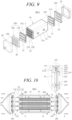
- FIG. 9 is an exploded perspective view illustrating the fuel cell membrane humidifier according to the third embodiment of the present invention
- FIG. 10 is an exploded cross-sectional view illustrating the fuel cell membrane humidifier according to the third embodiment of the present invention
- FIG. 11 is a cross-sectional view of the fuel cell membrane humidifier according to the third embodiment of the present invention.
- the fuel cell membrane humidifier 100-3 is substantially the same as the modification example 100a of the fuel cell membrane humidifiers according to the embodiments described above except that (i) a humidification module 110 includes two or more cartridges 112, (ii) a plurality of sub-cases 1100 formed to surround potting portions 112b of the two or more cartridges 112 are included, (iii) a body member 1211 of the packing portion 1210 includes two or more holes H2 into which the plurality of sub-cases 1100 are inserted, and (iv) two or more protrusion members 1212 formed at one end of the body member 1211 to come into contact with the sub-case 1100 are included.
- a plurality of cartridges 112 each including an inner case 112c are mounted in a mid-case 111, making it possible to distribute an off-gas to all hollow fiber membranes 112a present in the mid-case 111, and to selectively replace only the specific cartridge 112 in which a problem occurs, thereby further reducing a maintenance cost of the fuel cell membrane humidifier.
- FIGS. 12A, 12B and 13 are views illustrating side effects of the fuel cell membrane humidifier according to the embodiments of the present invention.
- FIG. 12A and 12B are view schematically illustrating a state in which the protrusion members 1212 directly press the potting portion 112b formed at the end of the cartridge 112 in a state in which there is no sub-case 1100, to make the space of the mid-case 111 and the space of the cap 120 airtight.
- the protrusion members 1212 directly press and come into contact with the potting portion 112b due to compressive force of the gasket 1200, thereby making the space of the mid-case 111 and the space of the cap 120 airtight.
- portions of the potting portion 112b coming into contact with the protrusion members 1212 according to the compressive force of the gasket 1200 are deformed and damaged, as illustrated in FIG. 12B .
- the damage of the potting portion 112b is accelerated, making it difficult for the potting portion 112b to perform an original function (division of a flow space).
- the protrusion members 1212 are prevented from coming into direct contact with the potting portion 112b by the sub-case 1100 as illustrated in FIG. 13 , it is possible to prevent the protrusion members 1212 from deforming and damaging the potting portion 112b according to the compression force of the gasket 1200.
Landscapes
- Chemical & Material Sciences (AREA)
- Chemical Kinetics & Catalysis (AREA)
- Life Sciences & Earth Sciences (AREA)
- Engineering & Computer Science (AREA)
- Manufacturing & Machinery (AREA)
- Sustainable Development (AREA)
- Sustainable Energy (AREA)
- Electrochemistry (AREA)
- General Chemical & Material Sciences (AREA)
- Fuel Cell (AREA)
- Separation Using Semi-Permeable Membranes (AREA)
Abstract
Description
- The present invention relates to a gasket assembly and a fuel cell membrane humidifier including the same, and more specifically, to a gasket assembly capable of being manufactured with improved productivity, dramatically reducing a maintenance cost, and reducing disturbance such as vibration generated by a repetitive operation of a fuel cell to improve humidification efficiency, and a fuel cell membrane humidifier including the same.
- Fuel cells are power generation cells that produce electricity through coupling between hydrogen and oxygen. The fuel cells have an advantage of being able to continuously produce electricity as long as the hydrogen and the oxygen are supplied, and having an efficiency that is about twice higher than an internal combustion engine because of no heat loss, unlike general chemical cells such as dry batteries or storage batteries.
- Further, since chemical energy generated through coupling between the hydrogen and the oxygen is directly converted into electrical energy, emission of pollutants is reduced. Therefore, the fuel cells have an advantage of being environmentally friendly and being able to reduce concerns about resource depletion due to increased energy consumption.
- These fuel cells are roughly classified into, for example, a polymer electrolyte membrane fuel cell (PEMFC), a phosphoric acid fuel cell (PAFC), a molten carbonate fuel cell (MCFC), a solid oxide fuel cell (SOFC), and an alkaline fuel cell (AFC) depending on a type of electrolyte used.
- These fuel cells fundamentally operate according to the same principle, but have a difference in a type of fuel used, an operating temperature, a catalyst, an electrolyte, or the like. Among the cells, the polymer electrolyte membrane fuel cell (PEMFC) is known to be the most promising not only for small-scale stationary power generation equipment but also for transportation systems because the polymer electrolyte membrane fuel cell operates at a lower temperature than other fuel cells and can be miniaturized due to a high output density.
- One of the most important factors in improving the performance of the polymer electrolyte membrane fuel cell (PEMFC) is to maintain moisture content by supplying a certain amount or more of moisture to a polymer electrolyte membrane (or proton exchange membrane: PEM) of a membrane electrode assembly (MEA). This is because the efficiency of power generation is rapidly degraded when the polymer electrolyte membrane is dried.
- Examples of a method for humidifying the polymer electrolyte membrane include 1) a bubbler humidification scheme for filling a pressure-resistant container with water and then passing a target gas through a diffuser to supply moisture, 2) a direct injection scheme for calculating a moisture supply amount required for a fuel cell reaction and directly supplying moisture to a gas flow pipe through a solenoid valve, and 3) a humidification membrane scheme for supplying moisture to a fluidized gas layer using a polymer separation membrane.
- Among these, the membrane humidification scheme for humidifying a polymer electrolyte membrane by providing water vapor to air supplied to the polymer electrolyte membrane using a membrane that selectively permeates only water vapor contained in an off-gas is advantageous in that a weight and size of a humidifier can be reduced.
- A selective permeable membrane used in the membrane humidification scheme is preferably a hollow fiber membrane having a large permeable area per unit volume when a module is formed. That is, when a humidifier is manufactured using hollow fiber membranes, there are advantages that high integration of the hollow fiber membranes with a large contact surface area is possible so that a fuel cell can be sufficiently humidified even with a small capacity, low-cost materials can be used, and moisture and heat contained in an off-gas discharged with a high temperature from the fuel cell can be recovered and can be reused through the humidifier.
-
FIG. 1 is an exploded perspective view illustrating a fuel cell membrane humidifier according to the related art. As illustrated inFIG. 1 , the fuelcell membrane humidifier 10 of the related art includes ahumidification module 11 in which moisture exchange between air supplied from the outside and an off-gas discharged from a fuel cell stack (not illustrated) occurs, andcaps 12 coupled to both ends of thehumidification module 11. - One of the
caps 12 supplies the air supplied from the outside to thehumidification module 11, and the other supplies air humidified by thehumidification module 11 to the fuel cell stack. - The
humidification module 11 includes a mid-case 11a having an off-gas inlet 11aa and an off-gas outlet 11ab, and a plurality of hollow fiber membranes 11b in the mid-case 11a. Both ends of a bundle of hollow fiber membranes 11b are fixed to pottingportions 11c. Thepotting portions 11c are generally formed by curing a liquid polymer such as a liquid polyurethane resin through a casting scheme. - The air supplied from the outside flows along hollows of the hollow fiber membranes 11b. The off-gas flowing into the mid-case 11a through the off-gas inlet 11aa comes into contact with outer surfaces of the hollow fiber membranes 11b, and then, is discharged from the mid-case 11a through the off-gas outlet 11ab. When the off-gas comes into contact with the outer surfaces of the hollow fiber membranes 11b, moisture contained in the off-gas permeates the hollow fiber membranes 11b to humidify the gas flowing along the hollows of the hollow fiber membranes 11b.
- Inner spaces of the
caps 12 are in fluid communication only with the hollows of the hollow fiber membranes 11b, and should be completely blocked from an inner space of the mid-case 11a. Otherwise, air leakage occurs due to a pressure difference, an amount of humidified air supplied to the fuel cell stack is reduced, and efficiency of power generation of the fuel cell is degraded. - In general, as illustrated in
FIG. 1 , thepotting portion 11c to which ends of the plurality of hollow fiber membranes 11b are fixed, and aresin layer 11d between thepotting portion 11c and the mid-case 11a block the inner spaces of thecaps 12 and the inner space of the mid-case 11a. Theresin layer 11d is generally formed by curing a liquid polymer such as liquid polyurethane resin through a casting scheme, similar to thepotting portion 11c. - However, since a casting process for forming the
resin layer 11d requires a relatively long process time, the productivity of themembrane humidifier 10 is degraded. - Further, since the
resin layer 11d is adhered to an inner wall of the mid-case 11a as well as thepotting portion 11c, theentire humidification module 11 should be replaced when a problem occurs in the hollow fiber membranes 11b, which incurs a huge maintenance cost. - Further, a repetitive operation of the fuel cell is highly likely to cause a gap between the
resin layer 11d and the mid-case 11a. That is, as an operation and stop of the fuel cell are repeated, expansion and contraction of theresin layer 11d alternately occur, and a difference in thermal expansion coefficient between the mid-case 11a and theresin layer 11d is highly likely to cause separation of theresin layer 11d from the mid-case 11a. As described above, when the gap is caused between theresin layer 11d and the mid-case 11a, air leakage occurs due to a pressure difference, an amount of humidified air supplied to the fuel cell stack is reduced, and the efficiency of power generation of the fuel cell is degraded. - An object of the present invention is to provide a gasket assembly capable of preventing problems caused by the limitations and disadvantages of the related arts as described above, being manufactured with improved productivity, dramatically reducing a maintenance cost, and reducing disturbance such as vibration generated by a repetitive operation of a fuel cell to improve humidification efficiency, and a fuel cell membrane humidifier including the same.
- The gasket assembly according to an embodiment of the present invention is
a gasket assembly for a fuel cell membrane humidifier including a mid-case, a cap fastened to the mid-case, and at least one cartridge disposed inside the mid-case and accommodating a plurality of hollow fiber membranes, the gasket assembly including: a sub-case formed in a shape surrounding an end of the cartridge and including a first hole into which the end of the cartridge is inserted; and a gasket including a packing portion having a second hole into which the sub-case is inserted and being in close contact with an outer circumferential surface of the sub-case inserted into the second hole to absorb vibration in a horizontal direction of the cartridge, an edge portion formed to be connected to the packing portion and interposed in a space formed by a groove formed at an end portion of the mid-case and an end portion of the cap, and a damping portion formed on the outer circumferential surface of the sub-case to absorb vibration in a vertical direction of the cartridge with a movement in the vertical direction suppressed by the packing portion. - In the gasket assembly according to the embodiment of the present invention, the packing portion may include a body member having a second hole into which the sub-case is inserted; and a protrusion member formed at one end of the body member and in close contact with the outer circumferential surface of the sub-case inserted into the second hole.
- In the gasket assembly according to the embodiment of the present invention, the body member may include two or more second holes into which two or more sub-cases are able to be inserted, and two or more protrusion members are included and formed in contact with outer circumferential surfaces of the two or more sub-cases.
- In the gasket assembly according to the embodiment of the present invention, the protrusion member may press and come into contact with the outer circumferential surface of the sub-case according to an elastic force to make a space on the mid-case side and a space on the cap side airtight.
- In the gasket assembly according to the embodiment of the present invention, the sub-case may be formed of a material having a hardness higher than a material constituting a potting portion formed at the end of the cartridge.
- In the gasket assembly according to the embodiment of the present invention, the gasket may further include a damping cap portion formed over an upper surface of the packing portion, an upper surface of the sub-case, and an upper surface of the cartridge to absorb the vibration in the vertical direction of the cartridge.
- In the gasket assembly according to the embodiment of the present invention, the packing portion may include two or more second holes into which two or more sub-cases are able to be inserted, and the damping portion is formed on an outer circumferential surface of each of the two or more sub-cases, to absorb a vibration in a vertical direction with a movement in the vertical direction suppressed by the packing portion.
- In the gasket assembly according to the embodiment of the present invention, an adhesive may be applied to an inner circumferential surface of the sub-case such that the sub-case is coupled to the end of the cartridge.
- In the gasket assembly according to the embodiment of the present invention, the edge portion may include edge wings protruding in both directions, and the edge wings are interposed with the groove formed at the end of the mid-case filled with the edge wings to seal the inside and outside of the mid-case, the mid-case, and the cap.
- In the gasket assembly according to the embodiment of the present invention, each of the packing portion and the edge portion may have a first hardness of 20 to 70 Shore A, and the gasket assembly may further include a reinforcing member formed to be inserted into at least a portion of the packing portion and at least a portion of the edge portion, the reinforcing member having a second hardness higher than the first hardness.
- Further, a fuel cell membrane humidifier according to an embodiment of the present invention includes a mid-case; a cap fastened to the mid-case; at least one cartridge disposed inside the mid-case and accommodating a plurality of hollow fiber membranes; and a gasket assembly airtightly coupled to at least one end of the humidification module through mechanical assembly so that the cap can be in fluid communication only with the hollow fiber membranes. The gasket assembly includes a sub-case formed in a shape surrounding an end of the cartridge and including a first hole into which the end of the cartridge is inserted; and a gasket including a packing portion having a second hole into which the sub-case is inserted and being in close contact with an outer circumferential surface of the sub-case inserted into the second hole to absorb vibration in a horizontal direction of the cartridge, an edge portion formed to be connected to the packing portion and interposed in a space formed by a groove formed at an end portion of the mid-case and an end portion of the cap, and a damping portion formed on the outer circumferential surface of the sub-case to absorb vibration in a vertical direction of the cartridge with a movement in the vertical direction suppressed by the packing portion.
- In the fuel cell membrane humidifier according to the embodiment of the present invention, the packing portion may include a body member having a second hole into which the sub-case is inserted; and a protrusion member formed at one end of the body member and in close contact with the outer circumferential surface of the sub-case inserted into the second hole.
- In the fuel cell membrane humidifier according to the embodiment of the present invention, the body member may include two or more second holes into which two or more sub-cases are able to be inserted, and two or more protrusion members are included and formed in contact with outer circumferential surfaces of the two or more sub-cases.
- In the fuel cell membrane humidifier according to the embodiment of the present invention, the protrusion member may press and come into contact with the outer circumferential surface of the sub-case according to an elastic force to make a space on the mid-case side and a space on the cap side airtight.
- In the fuel cell membrane humidifier according to the embodiment of the present invention, the sub-case may be formed of a material having a hardness higher than a material constituting a potting portion formed at the end of the cartridge.
- In the fuel cell membrane humidifier according to the embodiment of the present invention, the gasket may further include a damping cap portion formed over an upper surface of the packing portion, an upper surface of the sub-case, and an upper surface of the cartridge to absorb the vibration in the vertical direction of the cartridge.
- In the fuel cell membrane humidifier according to the embodiment of the present invention, the packing portion may include two or more second holes into which two or more sub-cases are able to be inserted, and the damping portion is formed on an outer circumferential surface of each of the two or more sub-cases, to absorb a vibration in a vertical direction with a movement in the vertical direction suppressed by the packing portion.
- In the fuel cell membrane humidifier according to the embodiment of the present invention, an adhesive may be applied to an inner circumferential surface of the sub-case such that the sub-case is coupled to the end of the cartridge.
- In the fuel cell membrane humidifier according to the embodiment of the present invention, the edge portion may include edge wings protruding in both directions, and the edge wings are interposed with the groove formed at the end of the mid-case filled with the edge wings to seal the inside and outside of the mid-case, the mid-case, and the cap.
- In the fuel cell membrane humidifier according to the embodiment of the present invention, each of the packing portion and the edge portion may have a first hardness of 20 to 70 Shore A, and the fuel cell membrane humidifier may further include a reinforcing member formed to be inserted into at least a portion of the packing portion and at least a portion of the edge portion, the reinforcing member having a second hardness higher than the first hardness.
- Other specific matters of implementation examples according to various aspects of the present invention are included in the detailed description below.
- According to the present invention, since air leakage between the mid-case and the cap is prevented through mechanical assembly of the gasket assembly, it is possible to omit, for example, a casting process (that is, a process of injecting a liquid polymer into a mold and curing the liquid polymer) and an additional sealing process (that is, a process of applying and curing a sealant) of the related art. Therefore, according to the present invention, it is possible to dramatically improve the productivity of the fuel cell membrane humidifier by reducing a production process time of the fuel cell membrane humidifier while preventing air leakage between the mid-case and the cap.
- Further, the gasket assembly of the present invention for preventing air leakage between the mid-case and the cap is mounted on the humidification module through mechanical assembly, and thus, when an abnormality occurs in a specific portion of the humidification module, it is possible to simply mechanically separate the gasket assembly, and then, repair or replace only the portion. Therefore, according to the present invention, it is possible to greatly reduce a maintenance cost of the fuel cell membrane humidifier.
- Further, since the protrusion member is prevented from coming into direct contact with the potting portion by the sub-case, it is possible to prevent the protrusion member from deforming and damaging the potting portion due to compressive force of the gasket assembly.
- Further, it is possible to improve the efficiency of power generation of the fuel cell by reducing disturbance such as vibration generated by a repetitive operation of the fuel cell to prevent air leakage due to a pressure difference between the mid-case and the cap.
-
-
FIG. 1 is an exploded perspective view illustrating a fuel cell membrane humidifier according to the related art. -
FIG. 2 is an exploded perspective view illustrating a fuel cell membrane humidifier according to a first embodiment of the present invention. -
FIG. 3 is an exploded cross-sectional view illustrating the fuel cell membrane humidifier according to the first embodiment of the present invention. -
FIG. 4 is a cross-sectional view of the fuel cell membrane humidifier according to the first embodiment of the present invention. -
FIG. 5 is an exploded perspective view illustrating a fuel cell membrane humidifier according to a second embodiment of the present invention. -
FIG. 6 is an exploded cross-sectional view illustrating the fuel cell membrane humidifier according to the second embodiment of the present invention. -
FIG. 7 is a cross-sectional view illustrating the fuel cell membrane humidifier according to the second embodiment of the present invention. -
FIG. 8 is a cross-sectional view illustrating a modification example of the fuel cell membrane humidifier according to the second embodiment of the present invention. -
FIG. 9 is an exploded perspective view illustrating a fuel cell membrane humidifier according to a third embodiment of the present invention. -
FIG. 10 is an exploded cross-sectional view illustrating the fuel cell membrane humidifier according to the third embodiment of the present invention. -
FIG. 11 is a cross-sectional view of the fuel cell membrane humidifier according to the third embodiment of the present invention. -
FIGS. 12A, 12B and13 are views illustrating side effects of the fuel cell membrane humidifier according to the embodiments of the present invention. - Since various changes may be made to the present invention, which may have several embodiments, specific embodiments will be illustrated and described in detail herein. However, it will be understood that this is not intended to limit the present invention to the specific embodiments, and all changes, equivalents, or substitutions included in the spirit and scope of the present invention are included.
- The terms used herein are used for the purpose of describing specific embodiments only and are not intended to limit the present invention. The singular expressions "a," "an" and "the" include the plural expressions, unless the context clearly indicates otherwise. It will be understood that the terms "include" or "have" herein specify the presence of features, numbers, steps, operations, components, parts or combinations thereof described herein, but do not preclude the presence or addition of one or more other features, numbers, steps, operations, components, parts or combinations thereof. Hereinafter, a gasket assembly and a fuel cell membrane humidifier including the same according to embodiments of the present invention will be described with reference to the drawings.
-
FIG. 2 is an exploded perspective view illustrating a fuel cell membrane humidifier according to a first embodiment of the present invention,FIG. 3 is an exploded cross-sectional view illustrating the fuel cell membrane humidifier according to the first embodiment of the present invention, andFIG. 4 is a cross-sectional view of the fuel cell membrane humidifier according to the first embodiment of the present invention. - Referring to
FIG. 2 , the fuel cell membrane humidifier 100-1 according to the first embodiment of the present invention includes ahumidification module 110 that humidifies air supplied from the outside with moisture in an off-gas discharged from a fuel cell stack. Both ends of thehumidification module 110 are coupled tocaps 120. - One of the
caps 120 supplies the air supplied from the outside to thehumidification module 110, and the other supplies the air humidified by thehumidification module 110 to the fuel cell stack. - The
humidification module 110 is a device in which moisture exchange between the air supplied from the outside and an off-gas occurs, and may include a mid-case 111 having an off-gas inlet 111a and an off-gas outlet 111b, and at least onecartridge 112 disposed in the mid-case 111. - The mid-case 111 and the
cap 120 may be independently formed of hard plastic or metal, and may have a cross section in a width direction having a circular or polygonal shape. The "circular shape" includes an oval shape, and the "polygonal shape" includes a polygonal shape with rounded corners. Examples of the hard plastic may include polycarbonate, polyamide (PA), polyphthalamide (PPA), and polypropylene (PP). - The
cartridge 112 may include a plurality ofhollow fiber membranes 112a and apotting portion 112b that fixes thehollow fiber membranes 112a to each other. Ends of thehollow fiber membranes 112a may be fixed to thepotting portion 112b. - The
hollow fiber membranes 112a may include a polymer membrane formed of a polysulfone resin, a polyethersulfone resin, a sulfonated polysulfone resin, a polyvinylidene fluoride (PVDF) resin, a polyacrylonitrile (PAN) resin, a polyimide resin, a polyamideimide resin, a polyesterimide resin, or a mixture of two or more of these, and thepotting portions 112b may be formed by curing a liquid resin such as a liquid polyurethane resin through a casting scheme such as deep potting or centrifugal potting. - The gas supplied from the outside flows along hollows of the
hollow fiber membranes 112a. The off-gas flowing into the mid-case 111 through the off-gas inlet 111a comes into contact with outer surfaces of thehollow fiber membranes 112a and then is discharged from the mid-case 111 through the off-gas outlet 111b. When the off-gas comes into contact with the outer surfaces of thehollow fiber membranes 112a, moisture contained in the off-gas permeates thehollow fiber membranes 112a to humidify the air flowing along the hollows of thehollow fiber membranes 112a. - The
cap 120 is in fluid communication only with the hollows of thehollow fiber membranes 112a and should be completely blocked from an inner space S of the mid-case 111. Otherwise, air leakage occurs due to a pressure difference, an amount of humidified air supplied to the fuel cell stack is reduced, and the efficiency of power generation of the fuel cell is degraded. - In order to solve this problem, the fuel cell membrane humidifier 100 of the present invention further includes a
gasket assembly 1000 that is airtightly coupled to each end of thehumidification module 110 through mechanical assembly. - According to the present invention, since air leakage between the mid-case 111 and the
cap 120 is prevented through mechanical assembly of thegasket assembly 1000, it is possible to omit, for example, a casting process (that is, a process of injecting a liquid resin into a mold and curing the liquid resin) and an additional sealing process (that is, a process of applying and curing a sealant) of the related art. Therefore, according to the present invention, it is possible to dramatically improve the productivity of the fuel cell membrane humidifier 100 (100-1, 100-2, and 100-3) by reducing a production process time of the fuel cell membrane humidifier 100 (100-1, 100-2, and 100-3) while preventing air leakage between the mid-case 111 and thecap 120. - Further, the
gasket assembly 1000 of the present invention is mounted on thehumidification module 110 through mechanical assembly, and thus, when an abnormality occurs in a specific portion (for example, the cartridge 112) of thehumidification module 110, it is possible to simply mechanically separate the sub-case 1100 and thegasket assembly 1000 from thehumidification module 110 and then, repair or replace only the portion. Therefore, according to the present invention, it is possible to greatly reduce a maintenance cost of the fuel cell membrane humidifier 100. - Further, it is possible to reduce disturbance such as vibration generated by a repetitive operation of the fuel cell to prevent air leakage due to a pressure difference between the mid-case 111 and the
cap 120, thereby improving the efficiency of power generation of the fuel cell. - Referring to
FIGS. 3 and 4 , thegasket assembly 1000 includes a sub-case 1100 and agasket 1200. - The sub-case 1100 is formed in a shape surrounding an end (for example, the
potting portion 112b) of thecartridge 112. The sub-case 1100 may be formed of a material having a hardness higher than a material constituting thepotting portion 112b. The sub-case 1100 includes a first hole H1 into which thepotting portion 112b of thecartridge 112 is inserted. Thepotting portion 112b of thecartridge 112 may be inserted into and fixed to the first hole H1 of the sub-case 1100. An adhesive such as a primer may be applied to an inner circumferential surface of the sub-case 1100 so that the sub-case 1100 can be coupled to thepotting portion 112b. Alternatively, aninner case 112c (seeFIG. 5 ) having thehollow fiber membrane 112a disposed therein may be inserting into and fixed to the first hole H1 of the sub-case 1100, and then, thepotting portion 112b may be formed. - The
gasket 1200 may include apacking portion 1210 and anedge portion 1220. Thepacking portion 1210 and theedge portion 1220 may be formed of an elastic material (for example, silicone or rubber) having a first hardness of 20 to 70 Shore A and, preferably, 30 to 60 Shore A. - The
packing portion 1210 includes a second hole H2 into which the sub-case 1100 is inserted and is interposed between the mid-case 111 and the sub-case 1100. Thepacking portion 1210 includes abody member 1211 and aprotrusion member 1212. - The
body member 1211 includes the second hole H2 into which the sub-case 1100 is inserted, and the second hole H2 is formed in a shape corresponding to that of the sub-case 1100. Alower body member 1211a formed to protrude downward from thebody member 1211 may have a cross section formed in a polygonal shape (for example, a trapezoidal shape), and anupper body member 1211b formed toward thecap 120 may be formed in a planar shape. Of course, theupper body member 1211b is not limited to the planar shape and may be formed in any of various shapes such as a curved surface and an inclined surface. A groove G into which anend portion 1 1 1aa of the mid-case 111 is fitted is formed between thelower body member 1211a and theedge portion 1220. - The
protrusion member 1212 is formed at one end of thebody member 1211 to come into contact with an outer circumferential surface of the sub-case 1100. Theprotrusion member 1212 may be at least one annular protrusion protruding from the one end of thebody member 1211. In the drawing, twoprotrusion members 1212 are illustrated. Theprotrusion member 1212 presses and comes into contact with the sub-case 1100 according to an elastic force to make a space of the mid-case 111 and a space of thecap 120 airtight. Therefore, theprotrusion member 1212 can prevent a fluid in the mid-case 111 from flowing into the space formed on thecap 120 side. Further, since theprotrusion member 1212 has elasticity, theprotrusion member 1212 can perform a vibration dampening function, and thus, prevent the membrane humidifier 100 from being damaged by vibration. In this case, since the sub-case 1100 prevents theprotrusion member 1212 from coming into direct contact with thepotting portion 112b, it is possible to prevent theprotrusion member 1212 from deforming and damaging thepotting portion 112b due to compressive force of thegasket 1200. - The
edge portion 1220 is formed at the other end of thebody member 1211. Theedge portion 1220 may be interposed in a space formed by a groove 111bb formed at an end of the mid-case and anend 120a of the cap. Theedge portion 1220 may includeedge wings edge wings humidification module 110. - When assembling is performed, the
edge wings edge wing 1222 is pressed by theend 120a of the cap, and then, assembly is performed by fastening using a fastening means such as a bolt B. In this case, since theedge wings edge wings edge wings cap 120. Theedge wings cap 120. - A damping
portion 1110 protruding in a radial direction may be formed on the outer circumferential surface of the sub-case 1100. The dampingportion 1110 may be formed in an annular ring shape on the outer circumferential surface of the sub-case 1100. The dampingportion 1110 may be formed to support thepacking portion 1210 by coming into contact with a lower surface of thepacking portion 1210. Specifically, at least a portion of the dampingportion 1110 may be formed to come into contact with a lower surface of thelower body member 1211a. Such a dampingportion 1110 may absorb a vibration in a vertical direction of the cartridge 212 with a movement in a vertical direction (a z-axis direction inFIG. 3 ) suppressed by thepacking portion 1210. This makes it possible to reduce disturbance caused by the vibration. - That is, the
packing portion 1210 absorbs vibration in a horizontal direction (an x-axis direction inFIG. 3 ) of thecartridge 112, and the dampingportion 1110 absorbs the vibration in the vertical direction of thecartridge 112 to reduce the disturbance caused by the vibration, thereby preventing air leakage from occurring due to a pressure difference between the mid-case 111 and thecap 120. - Further, the
gasket 1200 may further include a reinforcingmember 1240. The reinforcingmember 1240 may have a second hardness higher than the first hardness. For example, the reinforcingmember 1240 may be formed of metal, a thermoplastic or thermosetting resin, or the like. The reinforcingmember 1240 may be formed to be inserted into thegasket 1200 by being manufactured after a metal plate is inserted into a mold at the time of molding of thegasket 1200. The reinforcingmember 1240 may be formed to be inserted into at least a portion of thepacking portion 1210 and at least a portion of theedge portion 1220. The reinforcingmember 1240 may be formed at a portion of thegasket 1200 that is vulnerable to deformation (a portion in which the groove G is formed). The reinforcingmember 1240 having a hardness higher than thepacking portion 1210 and theedge portion 1220 can prevent thebody member 1211 from being deformed when thegasket assembly 1000 is mechanically assembled into thehumidification module 110 or while the membrane humidifier is operating, to block air leakage more reliably. - Next, a fuel cell membrane humidifier including a gasket assembly according to a second embodiment of the present invention will be described with reference to
FIGS. 5 to 7 .FIG. 5 is an exploded perspective view illustrating the fuel cell membrane humidifier including a gasket assembly according to the second embodiment of the present invention,FIG. 6 is an exploded cross-sectional view illustrating the fuel cell membrane humidifier including a gasket assembly according to the second embodiment of the present invention, andFIG. 7 is a cross-sectional view illustrating the fuel cell membrane humidifier including a gasket assembly according to the second embodiment of the present invention. - Referring to
FIGS. 5 to 7 , the gasket assembly according to the second embodiment of the present invention includes a sub-case 1100 and agasket 1200. - The sub-case 1100 may include a damping
portion 1110 protruding in a radial direction from an outer circumferential surface of the sub-case 1100, and thegasket 1200 may include apacking portion 1210, anedge portion 1220, a reinforcingmember 1240, and a dampingcap portion 1250. Since the dampingportion 1110, thepacking portion 1210, theedge portion 1220, and the reinforcingmember 1240 are substantially the same as those of the first embodiment, repeated description is omitted. - In the present embodiment, the damping
cap portion 1250 formed on one surface of thegasket 1200 is further included. - As illustrated in
FIGS. 5 to 7 , the dampingcap portion 1250 may be formed over at least a portion of an upper surface of thepacking portion 1210, an upper surface of the sub-case 1100, and an upper surface of thecartridge 112. - The damping
cap portion 1250 may be formed to come into contact with the outer circumferential surface of the sub-case 1100 or to be spaced apart by a predetermined distance from the outer circumferential surface of the sub-case 1100, and may be formed to come into contact with the upper surface of the sub-case 1100 and the upper surface of thepotting portion 112b. The dampingcap portion 1250 may be integrally formed as an annular ring having substantially a '' shape, or may be formed in a ring shape as a whole with a plurality of' ' shapes spaced apart from each other by a predetermined distance.
- The damping
cap portion 1250 may absorb vibration of thecartridge 112 in the vertical direction together with the dampingportion 1110. - Next, a modification example of the fuel cell membrane humidifier according to the second embodiment of the present invention will be described with reference to
FIG. 8. FIG. 8 is a cross-sectional view illustrating the modification example of the fuel cell membrane humidifier according to the second embodiment of the present invention. - Referring to
FIG. 8 , the modification example 100a of the fuel cell membrane humidifier according to the second embodiment of the present invention is substantially the same as the fuel cell membrane humidifier 100-2 according to the second embodiment described above except that (i) an inner space of a mid-case 111 is partitioned into a first space S1 and a second space S2 bypartitions 111d, and (ii) acartridge 112 further includes aninner case 112c. - The
inner case 112c has an opening at each end, andhollow fiber membranes 112a are accommodated in the opening. Pottingportions 112b to which ends of thehollow fiber membranes 112a are potted close the openings of theinner case 112c. - As illustrated in
FIG. 8 , at least a portion of thepotting portion 112b may be located outside theinner case 112c and exposed, and a sub-case 1100 may be formed to surround the exposedpotting portion 112b. - The
inner case 112c includes a plurality of holes (hereinafter referred to as 'first mesh holes') MH1 arranged in a mesh form for fluid communication with the first space S1, and a plurality of holes (hereinafter referred to as 'second mesh holes') MH2 arranged in a mesh form for fluid communication with the second space S2. - An off-gas flowing into the first space S1 of the mid-case 111 through an off-
gas inlet 111a flows into theinner case 112c through the first mesh holes MH1 and comes into contact with outer surfaces of thehollow fiber membranes 112a. Subsequently, the off-gas deprived of moisture exits to the second space S2 through the second mesh holes MH2, and then, is discharged from the mid-case 111 through an off-gas outlet 111b. - Such a
cartridge 112 including theinner case 112c has an advantage of being able to be easily assembled into the mid-case 111 and easily replaced. Of course, this characteristic ofFIG. 8 can also be applied to the fuel cell membrane humidifier according to the first embodiment described above. - Next, a fuel cell membrane humidifier according to a third embodiment of the present invention will be described with reference to
FIGS. 9 to 11 .FIG. 9 is an exploded perspective view illustrating the fuel cell membrane humidifier according to the third embodiment of the present invention,FIG. 10 is an exploded cross-sectional view illustrating the fuel cell membrane humidifier according to the third embodiment of the present invention, andFIG. 11 is a cross-sectional view of the fuel cell membrane humidifier according to the third embodiment of the present invention. - As illustrated in
FIGS. 9 to 11 , the fuel cell membrane humidifier 100-3 according to the third embodiment of the present invention is substantially the same as the modification example 100a of the fuel cell membrane humidifiers according to the embodiments described above except that (i) ahumidification module 110 includes two ormore cartridges 112, (ii) a plurality of sub-cases 1100 formed to surroundpotting portions 112b of the two ormore cartridges 112 are included, (iii) abody member 1211 of thepacking portion 1210 includes two or more holes H2 into which the plurality of sub-cases 1100 are inserted, and (iv) two ormore protrusion members 1212 formed at one end of thebody member 1211 to come into contact with the sub-case 1100 are included. - A plurality of
cartridges 112 each including aninner case 112c are mounted in a mid-case 111, making it possible to distribute an off-gas to allhollow fiber membranes 112a present in the mid-case 111, and to selectively replace only thespecific cartridge 112 in which a problem occurs, thereby further reducing a maintenance cost of the fuel cell membrane humidifier. - Next, side effects of the fuel cell membrane humidifier according to the embodiments of the present invention will be described with reference to
FIGS. 12A, 12B and13 .FIGS. 12A, 12B and13 are views illustrating side effects of the fuel cell membrane humidifier according to the embodiments of the present invention. - First,
FIG. 12A and 12B are view schematically illustrating a state in which theprotrusion members 1212 directly press thepotting portion 112b formed at the end of thecartridge 112 in a state in which there is no sub-case 1100, to make the space of the mid-case 111 and the space of thecap 120 airtight. - As illustrated in
FIG. 12A , theprotrusion members 1212 directly press and come into contact with thepotting portion 112b due to compressive force of thegasket 1200, thereby making the space of the mid-case 111 and the space of thecap 120 airtight. However, when the fuel cell membrane humidifier is repeatedly used for a long time, portions of thepotting portion 112b coming into contact with theprotrusion members 1212 according to the compressive force of thegasket 1200 are deformed and damaged, as illustrated inFIG. 12B . When the fuel cell membrane humidifier is continuously used in this state, the damage of thepotting portion 112b is accelerated, making it difficult for thepotting portion 112b to perform an original function (division of a flow space). - Meanwhile, in the present invention, since the
protrusion members 1212 are prevented from coming into direct contact with thepotting portion 112b by the sub-case 1100 as illustrated inFIG. 13 , it is possible to prevent theprotrusion members 1212 from deforming and damaging thepotting portion 112b according to the compression force of thegasket 1200. - Although the embodiment of the present invention has been described above, those skilled in the art can variously modify or change the present invention through affixation, change, deletion, addition, or the like of components without departing from the spirit of the present invention described in the claims, and this will be said to be also included within the scope of the present invention.
-
- 100 (100-1, 100-2, 100-3, 100a): fuel cell membrane humidifier
- 110: humidification module 111: mid-case
- 112:
cartridge 112b: potting portion - 112c: inner case 1000: gasket assembly
- 1100: sub-case 1110: damping portion
- 1200: gasket 1210: packing portion
- 1220: edge portion 1250: damping cap portion
Claims (20)
- A gasket assembly for a fuel cell membrane humidifier including a mid-case, a cap fastened to the mid-case, and at least one cartridge disposed inside the mid-case and accommodating a plurality of hollow fiber membranes, the gasket assembly comprising:a sub-case formed in a shape surrounding an end of the cartridge and including a first hole into which the end of the cartridge is inserted; anda gasket including a packing portion having a second hole into which the sub-case is inserted and being in close contact with an outer circumferential surface of the sub-case inserted into the second hole to absorb vibration in a horizontal direction of the cartridge, an edge portion formed to be connected to the packing portion and interposed in a space formed by a groove formed at an end portion of the mid-case and an end portion of the cap, and a damping portion formed on the outer circumferential surface of the sub-case to absorb vibration in a vertical direction of the cartridge with a movement in the vertical direction suppressed by the packing portion.
- The gasket assembly of claim 1,wherein the packing portion includesa body member having a second hole into which the sub-case is inserted; anda protrusion member formed at one end of the body member and in close contact with the outer circumferential surface of the sub-case inserted into the second hole.
- The gasket assembly of claim 2, wherein the body member includes two or more second holes into which two or more sub-cases are able to be inserted, and two or more protrusion members are included and formed in contact with outer circumferential surfaces of the two or more sub-cases.
- The gasket assembly of claim 2, wherein the protrusion member presses and comes into contact with the outer circumferential surface of the sub-case according to an elastic force to make a space on the mid-case side and a space on the cap side airtight.
- The gasket assembly of claim 1, wherein the sub-case is formed of a material having a hardness higher than a material constituting a potting portion formed at the end of the cartridge.
- The gasket assembly of claim 1, wherein the gasket further includes a damping cap portion formed over an upper surface of the packing portion, an upper surface of the sub-case, and an upper surface of the cartridge to absorb the vibration in the vertical direction of the cartridge.
- The gasket assembly of claim 1,wherein the packing portion includes two or more second holes into which two or more sub-cases are able to be inserted, andthe damping portion is formed on an outer circumferential surface of each of the two or more sub-cases, to absorb a vibration in a vertical direction with a movement in the vertical direction suppressed by the packing portion.
- The gasket assembly of claim 1, wherein an adhesive is applied to an inner circumferential surface of the sub-case such that the sub-case is coupled to the end of the cartridge.
- The gasket assembly of claim 1,wherein the edge portion includes edge wings protruding in both directions, andthe edge wings are interposed with the groove formed at the end of the mid-case filled with the edge wings to seal the inside and outside of the mid-case, the mid-case, and the cap.
- The gasket assembly of claim 1,wherein each of the packing portion and the edge portion has a first hardness of 20 to 70 Shore A, andthe gasket assembly further comprises a reinforcing member formed to be inserted into at least a portion of the packing portion and at least a portion of the edge portion, the reinforcing member having a second hardness higher than the first hardness.
- A fuel cell membrane humidifier comprising:a mid-case;a cap fastened to the mid-case;at least one cartridge disposed inside the mid-case and accommodating a plurality of hollow fiber membranes; anda gasket assembly airtightly coupled to at least one end of the humidification module through mechanical assembly so that the cap can be in fluid communication only with the hollow fiber membranes,wherein the gasket assembly includesa sub-case formed in a shape surrounding an end of the cartridge and including a first hole into which the end of the cartridge is inserted; anda gasket including a packing portion having a second hole into which the sub-case is inserted and being in close contact with an outer circumferential surface of the sub-case inserted into the second hole to absorb vibration in a horizontal direction of the cartridge, an edge portion formed to be connected to the packing portion and interposed in a space formed by a groove formed at an end portion of the mid-case and an end portion of the cap, and a damping portion formed on the outer circumferential surface of the sub-case to absorb vibration in a vertical direction of the cartridge with a movement in the vertical direction suppressed by the packing portion.
- The fuel cell membrane humidifier of claim 11,wherein the packing portion includesa body member having a second hole into which the sub-case is inserted; anda protrusion member formed at one end of the body member and in close contact with the outer circumferential surface of the sub-case inserted into the second hole.
- The fuel cell membrane humidifier of claim 12, wherein the body member includes two or more second holes into which two or more sub-cases are able to be inserted, and two or more protrusion members are included and formed in contact with outer circumferential surfaces of the two or more sub-cases.
- The fuel cell membrane humidifier of claim 12, wherein the protrusion member presses and comes into contact with the outer circumferential surface of the sub-case according to an elastic force to make a space on the mid-case side and a space on the cap side airtight.
- The fuel cell membrane humidifier of claim 11, wherein the sub-case is formed of a material having a hardness higher than a material constituting a potting portion formed at the end of the cartridge.
- The fuel cell membrane humidifier of claim 11, wherein the gasket further includes a damping cap portion formed over an upper surface of the packing portion, an upper surface of the sub-case, and an upper surface of the cartridge to absorb the vibration in the vertical direction of the cartridge.
- The fuel cell membrane humidifier of claim 11,wherein the packing portion includes two or more second holes into which two or more sub-cases are able to be inserted, andthe damping portion is formed on an outer circumferential surface of each of the two or more sub-cases, to absorb a vibration in a vertical direction with a movement in the vertical direction suppressed by the packing portion.
- The fuel cell membrane humidifier of claim 11, wherein an adhesive is applied to an inner circumferential surface of the sub-case such that the sub-case is coupled to the end of the cartridge.
- The fuel cell membrane humidifier of claim 11,wherein the edge portion includes edge wings protruding in both directions, andthe edge wings are interposed with the groove formed at the end of the mid-case filled with the edge wings to seal the inside and outside of the mid-case, the mid-case, and the cap.
- The fuel cell membrane humidifier of claim 11,wherein each of the packing portion and the edge portion has a first hardness of 20 to 70 Shore A, andthe fuel cell membrane humidifier further comprises a reinforcing member formed to be inserted into at least a portion of the packing portion and at least a portion of the edge portion, the reinforcing member having a second hardness higher than the first hardness.
Applications Claiming Priority (2)
| Application Number | Priority Date | Filing Date | Title |
|---|---|---|---|
| KR1020210016022A KR102755443B1 (en) | 2021-02-04 | 2021-02-04 | Gasket assembly and fuel cell membrane humidifier comprising it |
| PCT/KR2022/001199 WO2022169152A1 (en) | 2021-02-04 | 2022-01-24 | Gasket assembly and fuel cell membrane humidifier comprising same |
Publications (2)
| Publication Number | Publication Date |
|---|---|
| EP4270556A1 true EP4270556A1 (en) | 2023-11-01 |
| EP4270556A4 EP4270556A4 (en) | 2024-10-09 |
Family
ID=82741388
Family Applications (1)
| Application Number | Title | Priority Date | Filing Date |
|---|---|---|---|
| EP22749906.8A Pending EP4270556A4 (en) | 2021-02-04 | 2022-01-24 | FUEL CELL MEMBRANE HUMIDIFIER AND SEAL ASSEMBLY COMPRISING SAME |
Country Status (7)
| Country | Link |
|---|---|
| US (1) | US12671099B2 (en) |
| EP (1) | EP4270556A4 (en) |
| JP (2) | JP7581530B2 (en) |
| KR (1) | KR102755443B1 (en) |
| CN (1) | CN116868386A (en) |
| CA (1) | CA3206246A1 (en) |
| WO (1) | WO2022169152A1 (en) |
Families Citing this family (1)
| Publication number | Priority date | Publication date | Assignee | Title |
|---|---|---|---|---|
| KR102886437B1 (en) | 2025-01-14 | 2025-11-14 | 평화오일씰공업 주식회사 | Gasket of No Burr Style for Fuel Cell |
Family Cites Families (29)
| Publication number | Priority date | Publication date | Assignee | Title |
|---|---|---|---|---|
| EP0058275A1 (en) * | 1981-02-17 | 1982-08-25 | SENKO MEDICAL INSTRUMENT Mfg Co., LTD | Hollow fiber artificial kidney |
| SE9100167L (en) * | 1991-01-21 | 1992-07-22 | Gambro Dialysatoren | FILTERING AND / OR DIFFUSION DEVICE |
| ITMO20040180A1 (en) * | 2004-07-14 | 2004-10-14 | Gambo Lidia Ab | SEPARATION DEVICE AND SUPPORT FOR A SEPARATION DEVICE. |
| KR101278398B1 (en) | 2007-08-01 | 2013-06-24 | 코오롱인더스트리 주식회사 | Hollow Fiber Membrane and Method for Manufacturing The Same |
| KR101398779B1 (en) | 2007-12-03 | 2014-05-28 | 코오롱인더스트리 주식회사 | Fuel Cell Humidifier with Improved Cold Resistance |
| KR20090128005A (en) | 2008-06-10 | 2009-12-15 | 주식회사 코오롱 | Humidification system for fuel cell and fuel cell system using same |
| KR20100108092A (en) | 2009-03-27 | 2010-10-06 | 주식회사 코오롱 | Humidifier for fuel cell |
| KR101375447B1 (en) | 2009-06-08 | 2014-03-17 | 코오롱인더스트리 주식회사 | Humidifier for Fuel Cell |
| KR20110001022A (en) | 2009-06-29 | 2011-01-06 | 코오롱인더스트리 주식회사 | Polymer electrolyte membrane for fuel cell and manufacturing method thereof |
| KR20110006122A (en) | 2009-07-13 | 2011-01-20 | 코오롱인더스트리 주식회사 | Polymer electrolyte membrane for fuel cell and manufacturing method thereof |
| KR101577828B1 (en) | 2009-07-13 | 2015-12-28 | 코오롱인더스트리 주식회사 | Filling System used for preparation of Polymer Electrolyte Membrane and Method of manufacturing Polymer Electrolyte Membrane using the same |
| KR20110021217A (en) | 2009-08-25 | 2011-03-04 | 코오롱인더스트리 주식회사 | Polymer electrolyte membrane for fuel cell and manufacturing method thereof |
| KR20110026696A (en) | 2009-09-08 | 2011-03-16 | 코오롱인더스트리 주식회사 | Humidifier for fuel cell and its manufacturing method |
| WO2011068383A2 (en) | 2009-12-04 | 2011-06-09 | Kolon Industries, Inc. | Humidifier for fuel cell |
| KR101251256B1 (en) | 2011-03-09 | 2013-04-10 | 기아자동차주식회사 | Humidification device for fuel cell |
| US9190677B2 (en) * | 2011-12-29 | 2015-11-17 | Kolon Industries, Inc. | Membrane humidifier |
| KR101393558B1 (en) | 2012-09-20 | 2014-05-09 | 기아자동차 주식회사 | Humidification device for fuel cell |
| CN105142764B (en) * | 2013-04-25 | 2018-09-11 | 东丽株式会社 | Cartridge type hollow fiber film assembly |
| KR102240511B1 (en) * | 2017-12-29 | 2021-04-14 | 코오롱인더스트리 주식회사 | Fuel cell membrane humidifier |
| KR102263284B1 (en) * | 2018-06-05 | 2021-06-09 | 코오롱인더스트리 주식회사 | A membrane humidifier for fuel cell |
| WO2019132141A1 (en) * | 2017-12-29 | 2019-07-04 | 코오롱인더스트리 주식회사 | Membrane humidifier for fuel cell |
| KR102265021B1 (en) * | 2018-06-05 | 2021-06-14 | 코오롱인더스트리 주식회사 | A membrane humidifier for fuel cell |
| KR102717378B1 (en) * | 2018-07-27 | 2024-10-16 | 도레이 카부시키가이샤 | Hollow fiber desert module and method for manufacturing hollow fiber desert module |
| JP7402249B2 (en) | 2019-04-17 | 2023-12-20 | コーロン インダストリーズ インク | Humidifier for fuel cells and packing materials for it |
| WO2020262912A1 (en) * | 2019-06-25 | 2020-12-30 | 코오롱인더스트리 주식회사 | Humidifier for fuel cell and method for manufacturing same |
| CN114072942B (en) | 2019-06-25 | 2024-09-24 | 可隆工业株式会社 | Fuel cell humidifier and method for manufacturing the same |
| KR102704080B1 (en) * | 2019-11-29 | 2024-09-05 | 코오롱인더스트리 주식회사 | Humidifier for Fuel Cell |
| KR102137257B1 (en) * | 2019-12-17 | 2020-07-22 | 주식회사 퓨어엔비텍 | Hollow fiber membrane module for organic solvent nanofiltration |
| KR102577689B1 (en) * | 2020-05-22 | 2023-09-12 | 코오롱인더스트리 주식회사 | Gasket assembly and fuel cell humidifier comprising it |
-
2021
- 2021-02-04 KR KR1020210016022A patent/KR102755443B1/en active Active
-
2022
- 2022-01-24 CN CN202280013577.9A patent/CN116868386A/en active Pending
- 2022-01-24 EP EP22749906.8A patent/EP4270556A4/en active Pending
- 2022-01-24 JP JP2023543075A patent/JP7581530B2/en active Active
- 2022-01-24 WO PCT/KR2022/001199 patent/WO2022169152A1/en not_active Ceased
- 2022-01-24 CA CA3206246A patent/CA3206246A1/en active Pending
-
2023
- 2023-07-14 US US18/352,723 patent/US12671099B2/en active Active
-
2024
- 2024-10-30 JP JP2024190422A patent/JP7791962B2/en active Active
Also Published As
| Publication number | Publication date |
|---|---|
| KR20220112452A (en) | 2022-08-11 |
| EP4270556A4 (en) | 2024-10-09 |
| CN116868386A (en) | 2023-10-10 |
| WO2022169152A1 (en) | 2022-08-11 |
| JP7791962B2 (en) | 2025-12-24 |
| US20230361322A1 (en) | 2023-11-09 |
| US12671099B2 (en) | 2026-06-30 |
| KR102755443B1 (en) | 2025-01-21 |
| JP2025023965A (en) | 2025-02-19 |
| CA3206246A1 (en) | 2022-08-11 |
| JP2024505436A (en) | 2024-02-06 |
| JP7581530B2 (en) | 2024-11-12 |
Similar Documents
| Publication | Publication Date | Title |
|---|---|---|
| US20240063408A1 (en) | Fuel cell membrane humidifier preventing damage of humidification membrane | |
| US12394806B2 (en) | Gasket assembly and fuel cell humidifier comprising same | |
| US11870109B2 (en) | Gasket assembly and fuel cell humidifier including same | |
| JP7791962B2 (en) | Gasket assembly and fuel cell membrane humidifier including same | |
| EP4270555B1 (en) | Fuel cell membrane humidifier comprising gasket assembly | |
| EP4270558A1 (en) | Fuel cell membrane humidifier | |
| KR102926186B1 (en) | Fuel cell humidifier | |
| KR102925512B1 (en) | Fuel cell membrane humidifier | |
| EP4270557A1 (en) | Gasket assembly and fuel cell membrane humidifier including same | |
| CA3205730C (en) | Gasket assembly and fuel cell membrane humidifier comprising same | |
| KR20220111057A (en) | Fuel cell humidifier |
Legal Events
| Date | Code | Title | Description |
|---|---|---|---|
| STAA | Information on the status of an ep patent application or granted ep patent |
Free format text: STATUS: THE INTERNATIONAL PUBLICATION HAS BEEN MADE |
|
| PUAI | Public reference made under article 153(3) epc to a published international application that has entered the european phase |
Free format text: ORIGINAL CODE: 0009012 |
|
| STAA | Information on the status of an ep patent application or granted ep patent |
Free format text: STATUS: REQUEST FOR EXAMINATION WAS MADE |
|
| 17P | Request for examination filed |
Effective date: 20230724 |
|
| AK | Designated contracting states |
Kind code of ref document: A1 Designated state(s): AL AT BE BG CH CY CZ DE DK EE ES FI FR GB GR HR HU IE IS IT LI LT LU LV MC MK MT NL NO PL PT RO RS SE SI SK SM TR |
|
| DAV | Request for validation of the european patent (deleted) | ||
| DAX | Request for extension of the european patent (deleted) | ||
| A4 | Supplementary search report drawn up and despatched |
Effective date: 20240909 |
|
| RIC1 | Information provided on ipc code assigned before grant |
Ipc: H01M 8/10 20160101ALI20240903BHEP Ipc: H01M 8/0276 20160101ALI20240903BHEP Ipc: B01D 63/02 20060101ALI20240903BHEP Ipc: H01M 8/04119 20160101AFI20240903BHEP |
|
| STAA | Information on the status of an ep patent application or granted ep patent |
Free format text: STATUS: EXAMINATION IS IN PROGRESS |
|
| 17Q | First examination report despatched |
Effective date: 20250313 |